ES2902189T3 - Application nozzle for dermocosmetic treatment device for brown skin spots by cytoselective cryotherapy - Google Patents
Application nozzle for dermocosmetic treatment device for brown skin spots by cytoselective cryotherapy Download PDFInfo
- Publication number
- ES2902189T3 ES2902189T3 ES18833673T ES18833673T ES2902189T3 ES 2902189 T3 ES2902189 T3 ES 2902189T3 ES 18833673 T ES18833673 T ES 18833673T ES 18833673 T ES18833673 T ES 18833673T ES 2902189 T3 ES2902189 T3 ES 2902189T3
- Authority
- ES
- Spain
- Prior art keywords
- nozzle
- nozzle according
- gas
- longitudinal openings
- cryogenic
- Prior art date
- Legal status (The legal status is an assumption and is not a legal conclusion. Google has not performed a legal analysis and makes no representation as to the accuracy of the status listed.)
- Active
Links
Classifications
-
- A—HUMAN NECESSITIES
- A61—MEDICAL OR VETERINARY SCIENCE; HYGIENE
- A61B—DIAGNOSIS; SURGERY; IDENTIFICATION
- A61B18/00—Surgical instruments, devices or methods for transferring non-mechanical forms of energy to or from the body
- A61B18/02—Surgical instruments, devices or methods for transferring non-mechanical forms of energy to or from the body by cooling, e.g. cryogenic techniques
- A61B18/0218—Surgical instruments, devices or methods for transferring non-mechanical forms of energy to or from the body by cooling, e.g. cryogenic techniques with open-end cryogenic probe, e.g. for spraying fluid directly on tissue or via a tissue-contacting porous tip
-
- B—PERFORMING OPERATIONS; TRANSPORTING
- B05—SPRAYING OR ATOMISING IN GENERAL; APPLYING FLUENT MATERIALS TO SURFACES, IN GENERAL
- B05B—SPRAYING APPARATUS; ATOMISING APPARATUS; NOZZLES
- B05B1/00—Nozzles, spray heads or other outlets, with or without auxiliary devices such as valves, heating means
- B05B1/34—Nozzles, spray heads or other outlets, with or without auxiliary devices such as valves, heating means designed to influence the nature of flow of the liquid or other fluent material, e.g. to produce swirl
- B05B1/3402—Nozzles, spray heads or other outlets, with or without auxiliary devices such as valves, heating means designed to influence the nature of flow of the liquid or other fluent material, e.g. to produce swirl to avoid or to reduce turbulencies, e.g. comprising fluid flow straightening means
-
- A—HUMAN NECESSITIES
- A61—MEDICAL OR VETERINARY SCIENCE; HYGIENE
- A61B—DIAGNOSIS; SURGERY; IDENTIFICATION
- A61B18/00—Surgical instruments, devices or methods for transferring non-mechanical forms of energy to or from the body
- A61B2018/00315—Surgical instruments, devices or methods for transferring non-mechanical forms of energy to or from the body for treatment of particular body parts
- A61B2018/00452—Skin
- A61B2018/0047—Upper parts of the skin, e.g. skin peeling or treatment of wrinkles
-
- A—HUMAN NECESSITIES
- A61—MEDICAL OR VETERINARY SCIENCE; HYGIENE
- A61B—DIAGNOSIS; SURGERY; IDENTIFICATION
- A61B18/00—Surgical instruments, devices or methods for transferring non-mechanical forms of energy to or from the body
- A61B2018/00636—Sensing and controlling the application of energy
- A61B2018/00696—Controlled or regulated parameters
- A61B2018/00714—Temperature
-
- A—HUMAN NECESSITIES
- A61—MEDICAL OR VETERINARY SCIENCE; HYGIENE
- A61B—DIAGNOSIS; SURGERY; IDENTIFICATION
- A61B18/00—Surgical instruments, devices or methods for transferring non-mechanical forms of energy to or from the body
- A61B2018/00636—Sensing and controlling the application of energy
- A61B2018/00696—Controlled or regulated parameters
- A61B2018/00744—Fluid flow
-
- A—HUMAN NECESSITIES
- A61—MEDICAL OR VETERINARY SCIENCE; HYGIENE
- A61B—DIAGNOSIS; SURGERY; IDENTIFICATION
- A61B18/00—Surgical instruments, devices or methods for transferring non-mechanical forms of energy to or from the body
- A61B2018/0091—Handpieces of the surgical instrument or device
- A61B2018/00916—Handpieces of the surgical instrument or device with means for switching or controlling the main function of the instrument or device
Abstract
Boquilla para un dispositivo para el tratamiento dermocosmético de manchas cutáneas oscuras mediante crioterapia citoselectiva que comprende un chorro de pulverización suministrado por un tanque de gas criogénico licuado presurizado, dicha boquilla que comprende un anillo superior (11) de conexión a una carcasa (8), extendido por un cuerpo central (12) cuya pared lateral (12a) que se estrecha hacia abajo tiene aberturas longitudinales (10) y delimita una cámara de expansión de gas que comunica con un conducto de dispersión troncocónico (13a) dispuesto en el interior de una pieza de extremo (13) para ser aplicado sobre la piel y que abre al exterior a través de un puerto de descarga (13b), caracterizada porque dichas aberturas longitudinales (10) en la pared lateral (12a) tienen caras laterales (10a) que están, en la parte superior del cuerpo (12), ensanchadas y giradas hacia afuera de manera divergente, y, en la parte inferior de la cuerpo (12), ensanchadas y giradas hacia adentro de manera divergente.Nozzle for a device for the dermocosmetic treatment of dark skin spots by cytoselective cryotherapy comprising a spray jet supplied by a pressurized liquefied cryogenic gas tank, said nozzle comprising an upper ring (11) connected to a casing (8), extended by a central body (12) whose lateral wall (12a), which tapers downwards, has longitudinal openings (10) and delimits a gas expansion chamber that communicates with a frustoconical dispersion duct (13a) arranged inside a end piece (13) to be applied on the skin and that opens to the outside through a discharge port (13b), characterized in that said longitudinal openings (10) in the side wall (12a) have lateral faces (10a) that they are, in the upper part of the body (12), widened and turned outward in a divergent manner, and, in the lower part of the body (12), widened and turned inward from m divergent anera.
Description
DESCRIPCIÓNDESCRIPTION
Boquilla de aplicación para dispositivo de tratamiento dermocosmético para manchas cutáneas marrones mediante crioterapia citoselectivaApplication nozzle for dermocosmetic treatment device for brown skin spots by cytoselective cryotherapy
La invención se refiere a una mejora de un dispositivo para el tratamiento dermocosmético para manchas marrones cutáneas mediante crioterapia citoselectiva.The invention refers to an improvement of a device for the dermocosmetic treatment of cutaneous brown spots by means of cytoselective cryotherapy.
Más precisamente, la invención se refiere a una boquilla mejorada destinada a integrarse en un dispositivo de tratamiento cosmético para manchas cutáneas marrones mediante crioterapia, así como también al dispositivo de tratamiento equipado con dicha boquilla.More precisely, the invention relates to an improved nozzle intended to be integrated into a cosmetic treatment device for brown skin spots by cryotherapy, as well as to the treatment device equipped with said nozzle.
Descripción de la invenciónDescription of the invention
El dispositivo de tratamiento al que se refiere la invención busca, más particularmente, el tratamiento dermocosmético de las manchas marrones situadas en las manos, la cara, las extremidades y el escote de sujetos que padecen este tipo de hiperpigmentación cutánea.The treatment device to which the invention relates seeks, more particularly, the dermocosmetic treatment of brown spots located on the hands, face, limbs and neckline of subjects suffering from this type of cutaneous hyperpigmentation.
Un dispositivo de este tipo se describe en el documento WO2016113305 y comprende un tanque de fluido criogénico a presión, una electroválvula que permite la descarga del fluido desde el interior del tanque a un chorro de pulverización que dirige el fluido, a través de una boquilla, a la zona de la piel que será tratada.A device of this type is described in document WO2016113305 and comprises a pressurized cryogenic fluid tank, a solenoid valve that allows the discharge of the fluid from inside the tank to a spray jet that directs the fluid, through a nozzle, to the skin area to be treated.
La boquilla de pulverización comprende al menos un conducto interior axial y cilíndrico-cónico que forma un medio para limitar el caudal de fluido criogénico.The spray nozzle comprises at least one internal axial and cylindrical-conical conduit that forms a means to limit the flow of cryogenic fluid.
La electroválvula está asociada a un sistema de temporización electrónico que permite su apertura durante un período predeterminado.The solenoid valve is associated with an electronic timing system that allows it to open for a predetermined period.
La transición de la fase líquida a la fase gaseosa, por expansión del fluido criogénico, se produce en la boquilla que está destinada a producir el efecto criogénico deseado mientras está en contacto con la zona de destino de la piel, es decir, la zona en la que se ubica una mancha marrón para hacer desaparecer.The transition from the liquid phase to the gas phase, by expansion of the cryogenic fluid, occurs in the nozzle that is intended to produce the desired cryogenic effect while in contact with the target area of the skin, that is, the area in which a brown spot is located to make disappear.
La boquilla es, por tanto, uno de los componentes esenciales del dispositivo de tratamiento cosmético porque condiciona el potencial criogénico del gas y su impacto en la zona de destino de la epidermis, y por tanto tiene una influencia directa sobre la eficacia del tratamiento.The nozzle is, therefore, one of the essential components of the cosmetic treatment device because it conditions the cryogenic potential of the gas and its impact on the target area of the epidermis, and therefore has a direct influence on the efficacy of the treatment.
El documento US2004/102768A1 describe un dispositivo de tratamiento cosmético que usa crioterapia, en particular una boquilla provista de un anillo superior prolongado por un cuerpo central cuya pared lateral tiene aberturas longitudinales en su parte inferior y delimita una cámara de expansión de gas criogénico que se comunica con un conducto de dispersión proporcionado dentro de una pieza de extremo de aplicación y que se abre hacia el exterior a través de un puerto de descarga.Document US2004/102768A1 describes a cosmetic treatment device that uses cryotherapy, in particular a nozzle provided with an upper ring extended by a central body whose side wall has longitudinal openings in its lower part and delimits a cryogenic gas expansion chamber that is It communicates with a dispersion conduit provided within an application end piece and opening outwards through a discharge port.
Además, el tratamiento dermocosmético que implica varias aplicaciones sucesivas del fluido criogénico sobre la piel, su eficacia depende de las condiciones de aplicación del fluido que deben ser reproducibles con mucha precisión. Más precisamente, debido al hecho de que el fluido criogénico pasa de una fase líquida a una fase gaseosa antes de llegar a su objetivo, las características de la boquilla de aplicación, que es el lugar de esta transición, son importantes para obtener una curva de temperatura óptima.In addition, the dermocosmetic treatment that involves several successive applications of the cryogenic fluid on the skin, its effectiveness depends on the conditions of application of the fluid that must be reproducible with great precision. More precisely, due to the fact that the cryogenic fluid passes from a liquid phase to a gas phase before reaching its target, the characteristics of the application nozzle, which is the place of this transition, are important to obtain a curve of optimal temperature.
El seguimiento de esta curva de temperatura, denominada curva de temperatura de referencia, permite crear un choque térmico, luego osmótico, que impacta en los melanocitos lo que conserva el resto de células de la epidermis y de la dermis y, por tanto, mantienen el carácter citoselectivo del tratamiento dermocosmético.Following this temperature curve, called the reference temperature curve, makes it possible to create a thermal shock, then an osmotic shock, which impacts the melanocytes, which preserves the rest of the cells of the epidermis and dermis and, therefore, maintains the cytoselective nature of dermocosmetic treatment.
Cualitativamente, esta curva de temperatura de referencia comprende un descenso rápido de la temperatura hasta alcanzar un nivel delimitado por un intervalo de temperaturas, el mantenimiento de la temperatura en este intervalo de temperaturas durante un período determinado, antes de provocar un aumento progresivo de la temperatura hasta llegar a su valor inicial.Qualitatively, this reference temperature curve comprises a rapid decrease in temperature until reaching a level delimited by a range of temperatures, maintaining the temperature in this range of temperatures for a given period, before causing a progressive increase in temperature. until reaching its initial value.
En consecuencia, el paso del fluido criogénico de una fase líquida a una fase gaseosa al seguir la curva de referencia está bajo la influencia de varios parámetros, entre ellos:Consequently, the passage of the cryogenic fluid from a liquid phase to a gas phase following the reference curve is under the influence of several parameters, including:
- el volumen de la cámara de expansión de gas, así como también el área superficial relativa de sus aberturas para comunicarse con el exterior y, por tanto, el perfil de la boquilla, - the volume of the gas expansion chamber, as well as the relative surface area of its openings to communicate with the outside and, therefore, the profile of the nozzle,
- la distancia entre la salida del chorro de pulverización y la zona de destino de la piel sobre la que se aplicará el efecto criogénico, y por tanto la altura de la boquilla y, en particular, la de la pieza de extremo de aplicación que se dispone en la salida de la cámara de expansión. - the distance between the spray jet outlet and the target area of the skin on which the cryogenic effect will be applied, and therefore the height of the nozzle and, in particular, that of the application end piece to be applied available at the outlet of the expansion chamber.
De hecho, el perfil de esta boquilla ha demostrado ser técnicamente muy importante porque el efecto criogénico deseado genera la formación de agua cristalizada o escarcha en la zona de destino de la epidermis, lo que permite mantener una temperatura negativa estable durante un período determinado. Así, una boquilla con una forma demasiado plana no permitiría mantener la temperatura en el intervalo preferido el tiempo suficiente, mientras que una forma demasiado profunda provocaría un período de contacto demasiado largo entre el objetivo y el agua cristalizada, lo que genera temperaturas excesivamente bajas.In fact, the profile of this nozzle has proven to be technically very important because the desired cryogenic effect generates the formation of crystallized water or frost in the target area of the epidermis, which makes it possible to maintain a stable negative temperature for a certain period. Thus, too flat a nozzle shape would not allow the temperature to be maintained in the preferred range long enough, while too deep a shape would result in too long a contact period between the target and the crystallized water, resulting in excessively low temperatures.
En estas últimas condiciones, la curva de temperatura obtenida no podría corresponder a la curva de referencia. Paralelamente, si la altura y/o el área superficial de las aberturas de la boquilla son demasiado pequeñas, el gas no tiene posibilidad de expandirse y se proyecta sobre la zona de destino en forma de una mezcla de gotitas y de gas. Esta fase líquida luego se acumula en la zona de destino, se expande progresivamente y genera así variaciones incontroladas e irreproducibles de temperatura.Under these latter conditions, the temperature curve obtained could not correspond to the reference curve. In parallel, if the height and/or surface area of the nozzle openings are too small, the gas has no chance to expand and is projected onto the target area as a mixture of droplets and gas. This liquid phase then accumulates in the destination zone, progressively expands and thus generates uncontrolled and irreproducible variations in temperature.
En el caso contrario, el gas se dispersa por completo en el volumen interior de la boquilla y, por tanto, no aporta todo su potencial criogénico al tratamiento.In the opposite case, the gas is completely dispersed in the interior volume of the nozzle and, therefore, does not contribute its full cryogenic potential to the treatment.
En ambas situaciones, la curva de temperatura obtenida en la zona a tratar se desvía considerablemente de la curva de referencia correspondiente a un tratamiento dermocosmético óptimo.In both situations, the temperature curve obtained in the area to be treated deviates considerably from the reference curve corresponding to an optimal dermo-cosmetic treatment.
La boquilla de la invención busca conseguir los objetivos de rendimiento definidos anteriormente al producir un efecto criogénico reproducible y homogéneo sobre la zona a tratar sin modificar las propiedades criogénicas intrínsecas del gas y permitir así un tratamiento dermocosmético eficaz.The nozzle of the invention seeks to achieve the performance objectives defined above by producing a reproducible and homogeneous cryogenic effect on the area to be treated without modifying the intrinsic cryogenic properties of the gas and thus allowing an effective dermo-cosmetic treatment.
Este objetivo se consigue de acuerdo con la invención mediante una boquilla, caracterizada porque comprende un anillo superior de conexión a una carcasa, prolongado por un cuerpo central cuya pared lateral que se estrecha hacia abajo tiene aberturas longitudinales y delimita una cámara de expansión de gas comunicante con un conducto de dispersión troncocónico proporcionado dentro de una pieza de extremo de aplicación en la piel y que se abre al exterior a través de un puerto de descarga.This objective is achieved according to the invention by means of a nozzle, characterized in that it comprises an upper ring for connection to a casing, extended by a central body whose side wall, which tapers downwards, has longitudinal openings and delimits a communicating gas expansion chamber. with a frustoconical dispersion conduit provided within a skin engaging end piece and opening to the outside through a discharge port.
De acuerdo con una característica específica de la invención, las caras laterales de las aberturas longitudinales están, en la parte superior del cuerpo, ensanchadas y giradas hacia fuera de manera divergente y, en la parte inferior del cuerpo, ensanchadas y giradas hacia adentro de manera divergente.According to a specific feature of the invention, the lateral faces of the longitudinal openings are, in the upper part of the body, widened and turned outward in a divergent manner and, in the lower part of the body, widened and turned inward in a divergent manner. divergent.
De acuerdo con una primera variante de la boquilla de la invención, las aberturas longitudinales tienen caras laterales en espiral.According to a first variant of the nozzle of the invention, the longitudinal openings have spiral lateral faces.
De acuerdo con una característica ventajosa, la altura del conducto de dispersión troncocónico y su diámetro son respectivamente menores o iguales a 10 mm.According to an advantageous feature, the height of the frustoconical dispersion duct and its diameter are respectively less than or equal to 10 mm.
Este conducto se abre hacia el exterior a través de un puerto de descarga que tiene un desplazamiento axial con relación al eje del cuerpo.This conduit opens towards the outside through a discharge port which has an axial displacement in relation to the axis of the body.
Preferentemente, este desplazamiento está comprendido entre 1,5 y 3,5 mm.Preferably, this displacement is between 1.5 and 3.5 mm.
De acuerdo con otra característica, la altura de la cámara de expansión está comprendida entre 35 y 55 mm.According to another feature, the height of the expansion chamber is between 35 and 55 mm.
De acuerdo con otra característica, el área superficial total de las hendiduras longitudinales está comprendida entre 1080 mm2 y 2160 mm2.According to another characteristic, the total surface area of the longitudinal grooves is between 1080 mm2 and 2160 mm2.
De acuerdo con una variante de modalidad específica de la boquilla, la sección transversal del cuerpo central es sustancialmente trapezoidal y decreciente de arriba a abajo.According to a specific embodiment variant of the nozzle, the cross section of the central body is substantially trapezoidal and decreases from top to bottom.
De acuerdo con una característica específica, la pared lateral del cuerpo tiene una inclinación de aproximadamente 8° con relación al eje longitudinal de la boquilla.According to a specific characteristic, the lateral wall of the body has an inclination of approximately 8° in relation to the longitudinal axis of the nozzle.
Otro objeto de la invención es un dispositivo para el tratamiento dermocosmético de manchas marrones cutáneas que comprende una boquilla que tiene las características definidas anteriormente.Another object of the invention is a device for the dermo-cosmetic treatment of brown skin spots comprising a nozzle having the characteristics defined above.
La boquilla de la invención permite obtener un efecto criogénico sobre la piel que se ajusta a la curva de referencia correspondiente a un tratamiento dermocosmético óptimo de las manchas marrones.The nozzle of the invention makes it possible to obtain a cryogenic effect on the skin that fits the reference curve corresponding to an optimal dermo-cosmetic treatment of brown spots.
Debido a esta boquilla, el efecto criogénico se concentra en una zona de destino de la piel con una pequeña área superficial. El dispositivo equipado con la boquilla permite la implementación de un tratamiento dermocosmético particularmente efectivo, cuyas secuencias son reproducibles de manera consistente con gran precisión de los parámetros físico-químicos. Due to this nozzle, the cryogenic effect is concentrated on a target area of the skin with a small surface area. The device equipped with the nozzle allows the implementation of a particularly effective dermocosmetic treatment, whose sequences are consistently reproducible with great precision of the physical-chemical parameters.
finalmente, gracias a esta boquilla, el efecto criogénico se distribuye homogéneamente sobre la zona de destino de la piel antes mencionada.Finally, thanks to this nozzle, the cryogenic effect is distributed homogeneously over the aforementioned target area of the skin.
Breve descripción de las figurasBrief description of the figures
Otras características y ventajas de la invención se revelarán al leer la descripción que sigue, con referencia a las figuras adjuntas que se describen en detalle a continuación.Other features and advantages of the invention will become apparent upon reading the description which follows, with reference to the accompanying figures which are described in detail below.
La Figura 1 muestra una vista en perspectiva despiezada de un dispositivo de tratamiento criogénico equipado con una modalidad de la boquilla de la invención.Figure 1 shows an exploded perspective view of a cryogenic treatment device equipped with an embodiment of the nozzle of the invention.
Las Figuras 2A, 2B y 2C son respectivamente vistas frontales, de perfil y superior de la boquilla de la Figura 1.Figures 2A, 2B and 2C are respectively front, profile and top views of the nozzle of Figure 1.
Las Figuras 3A, 3B y 3C son vistas en sección del cuerpo de la boquilla de las figuras 1 y 2B en tres planos A, B, C distintos y paralelos.Figures 3A, 3B and 3C are sectional views of the body of the nozzle of figures 1 and 2B in three different and parallel planes A, B, C.
La Figura 4 es un gráfico que muestra la curva de referencia del tratamiento dermocosmético implementado con el dispositivo de la invención.Figure 4 is a graph that shows the reference curve of the dermocosmetic treatment implemented with the device of the invention.
La Figura 5 es una vista en sección esquemática que ilustra el flujo de gas en la boquilla de la invención. La Figura 6 es una vista en perspectiva del dispositivo de tratamiento de crioterapia equipado con la boquilla de la invención.Figure 5 is a schematic sectional view illustrating the flow of gas in the nozzle of the invention. Figure 6 is a perspective view of the cryotherapy treatment device equipped with the nozzle of the invention.
Para mayor claridad, los elementos idénticos o similares se indican con signos de referencia idénticos en todas las figuras.For clarity, identical or similar elements are indicated by identical reference signs throughout the figures.
Descripción detallada de las modalidadesDetailed description of the modalities
Naturalmente, las modalidades ilustradas por las figuras presentadas a continuación se dan solo a manera de ejemplos no limitativos. También se proporciona, de acuerdo con la invención, que sea posible combinar estas diferentes modalidades para proponer otras.Naturally, the modalities illustrated by the figures presented below are given only by way of non-limiting examples. It is also provided, according to the invention, that it is possible to combine these different modalities to propose others.
El dispositivo de tratamiento como se muestra en la Figura 6 comprende un tanque 2 de fluido criogénico a presión (a aproximadamente 6 bares), una electroválvula 3 montada en la salida del tanque 2 y controlada por un circuito electrónico 30, un chorro de pulverización 4, una boquilla 1, una junta 6 y una batería 7 (que consta aquí de dos celdas). Todos estos elementos están encerrados en una carcasa formada aquí por una carcasa 8 resultante del montaje de dos medias carcasas.The treatment device as shown in Figure 6 comprises a pressurized cryogenic fluid tank 2 (at approximately 6 bars), a solenoid valve 3 mounted on the outlet of tank 2 and controlled by an electronic circuit 30, a spray jet 4 , a nozzle 1, a gasket 6 and a battery 7 (consisting here of two cells). All these elements are enclosed in a casing formed here by a casing 8 resulting from the assembly of two half casings.
La boquilla de aplicación 1 es uno de los componentes esenciales del dispositivo para el tratamiento de manchas marrones. Esto condiciona el potencial criogénico del gas y su impacto en la zona de destino de la piel y por tanto influye directamente en la eficacia clínica del tratamiento dermocosmético.The application nozzle 1 is one of the essential components of the device for the treatment of brown spots. This determines the cryogenic potential of the gas and its impact on the target area of the skin and therefore directly influences the clinical efficacy of the dermo-cosmetic treatment.
El fluido criogénico es un gas que se encuentra en fase líquida y bajo presión en el tanque 2. El tanque 2 está siempre en posición abierta y se bloquea por la electroválvula 3 montada directamente en su tubo de escape 20. Cuando la electroválvula 3 pasa a la posición abierta, el fluido sale automáticamente del tanque 2 en la dirección del chorro de pulverización 4. Las fases de apertura y cierre de la electroválvula 3 son controladas por el circuito electrónico 30 que gestiona estas secuencias.The cryogenic fluid is a gas that is in liquid phase and under pressure in tank 2. Tank 2 is always in the open position and is blocked by solenoid valve 3 mounted directly on its exhaust pipe 20. When solenoid valve 3 goes into the open position, the fluid automatically leaves the tank 2 in the direction of the spray jet 4. The opening and closing phases of the solenoid valve 3 are controlled by the electronic circuit 30 that manages these sequences.
A la salida del chorro de pulverización 4, el fluido penetra en la boquilla 1, donde realiza su transición entre su fase líquida y su fase gaseosa (expansión del gas) hasta llegar a la zona de destino de la piel para producir allí el efecto criogénico deseado.At the outlet of the spray jet 4, the fluid enters the nozzle 1, where it makes its transition between its liquid phase and its gas phase (gas expansion) until it reaches the target area of the skin to produce the cryogenic effect there. wanted.
Las Figuras 1, 2A, 2B y 2C muestran una modalidad preferida de la boquilla 1 de la invención.Figures 1, 2A, 2B and 2C show a preferred embodiment of the nozzle 1 of the invention.
Esta boquilla 1, de eje longitudinal X, comprende un anillo superior 11 que proporciona su conexión y su fijación irreversible a la carcasa 8. Con este fin, el anillo 11 incluye miembros de bloqueo (que usan trinquete, por ejemplo), aquí en forma de dos puertos 11a destinados a recibir púas complementarias (no mostradas) llevadas por la base de la carcasa 8.This nozzle 1, of longitudinal axis X, comprises an upper ring 11 that provides its connection and its irreversible fixation to the casing 8. To this end, the ring 11 includes locking members (using ratchets, for example), here in the form of two ports 11a intended to receive complementary spikes (not shown) carried by the base of the casing 8.
En la modalidad mostrada en las figuras, el anillo 11 se prolonga en su parte inferior por un cuerpo central 12 con una sección transversal sustancialmente trapezoidal, cuya pared lateral 12a está inclinada mientras se estrecha hacia abajo en un ángulo de aproximadamente 8° con relación al eje longitudinal de la boquilla 1. In the embodiment shown in the figures, the ring 11 is extended in its lower part by a central body 12 with a substantially trapezoidal cross-section, the side wall 12a of which is inclined while narrowing downwards at an angle of approximately 8° relative to the longitudinal axis of nozzle 1.
Sin embargo, sería posible, sin apartarse del alcance de la invención, crear el cuerpo 12 con una forma cilindrica. La pared 12a del cuerpo 12, que localmente presenta aberturas 10 pasantes longitudinales, delimita en su interior una cámara de expansión para el gas criogénico. Las aberturas 10 proporcionan, en particular, comunicación desde esta cámara al entorno exterior circundante que está a temperatura ambiente y presión atmosférica.However, it would be possible, without departing from the scope of the invention, to create the body 12 in a cylindrical shape. The wall 12a of the body 12, which locally has longitudinal through openings 10, delimits in its interior an expansion chamber for the cryogenic gas. The openings 10 provide, in particular, communication from this chamber to the surrounding outside environment which is at room temperature and atmospheric pressure.
De acuerdo con una variante preferida, las aberturas longitudinales 10 consisten en una serie de hendiduras, aquí 9 hendiduras, cada una de las cuales tiene una altura de 40 mm y un ancho comprendido entre 6 mm y 7 mm, preferentemente igual a 6,7 mm. Estas hendiduras están delimitadas por bordes o caras laterales 10a proporcionados en la pared 12a del cuerpo 12 y cuyo perfil está generalmente biselado al hacer espirales sobre su altura.According to a preferred variant, the longitudinal openings 10 consist of a series of slits, here 9 slits, each of which has a height of 40 mm and a width of between 6 mm and 7 mm, preferably equal to 6.7 mm. mm. These grooves are delimited by edges or lateral faces 10a provided in the wall 12a of the body 12 and whose profile is generally beveled by spiraling over its height.
Más precisamente y como se ilustra en las figuras 2B, 2C y 3A a 3C, en cada hendidura 10, las caras 10a enfrentadas se giran mientras se ensanchan, por un lado, hacia afuera en la parte superior del cuerpo 12 (figuras 3A) y, por otro lado, hacia adentro en la parte inferior (Figura 3C). La línea de inversión 10b de la orientación de estas caras está dispuesta sustancialmente a media altura de las hendiduras 10, es decir, en el plano de sección de la Figura 3B donde las caras 10a son localmente paralelas.More precisely and as illustrated in Figures 2B, 2C and 3A to 3C, in each slit 10, the facing faces 10a are rotated while they widen, on one side, outwards in the upper part of the body 12 (Figures 3A) and , on the other hand, inward at the bottom (Figure 3C). The reversal line 10b of the orientation of these faces is arranged substantially halfway up the slits 10, that is, in the section plane of Figure 3B where the faces 10a are locally parallel.
Debido a este perfil específico, (cuyas funciones y la influencia en el flujo de gas criogénico se describirán con más detalle a continuación), las aberturas 10 contribuyen a reforzar el flujo de gas laminar mientras que permiten que el gas se expanda de manera homogénea dentro de la cámara del cuerpo 12. Esta expansión lleva el gas a la presión atmosférica y, por tanto, tiene un impacto en su potencial criogénico y su eficacia dermocosmética. El área superficial de la abertura del cuerpo, así como también el perfil y la geometría de las aberturas 10 son parámetros esenciales para optimizar las propiedades criogénicas de los gases, como demuestran a continuación los ensayos realizados.Due to this specific profile, (whose functions and influence on the cryogenic gas flow will be described in more detail below), the openings 10 contribute to reinforcing the laminar gas flow while allowing the gas to expand homogeneously within. of the body chamber 12. This expansion brings the gas to atmospheric pressure and therefore has an impact on its cryogenic potential and dermo-cosmetic efficacy. The surface area of the opening of the body, as well as the profile and geometry of the openings 10 are essential parameters for optimizing the cryogenic properties of the gases, as the tests performed below demonstrate.
De hecho, el gas que se encuentra en fase líquida en el tanque 2 no se expande a partir de la salida de la electroválvula 3. Por tanto, este gas llega a través de la junta 6 en el chorro de pulverización 4, que permanece todavía en estado líquido. Sólo a la salida del chorro de pulverización 4 pasa de la fase líquida a la fase gaseosa por expansión. La presión a lo largo de esta trayectoria, luego durante la transformación de la fase líquida a la fase gaseosa, genera la creación de un flujo laminar en la salida del chorro de pulverización 4, como se ilustra en la Figura 5.In fact, the gas that is in liquid phase in tank 2 does not expand from the outlet of solenoid valve 3. Therefore, this gas arrives through joint 6 in spray jet 4, which still remains in liquid state. Only at the outlet of the spray jet 4 does it pass from the liquid phase to the gaseous phase by expansion. The pressure along this path, then during the transformation from the liquid phase to the gas phase, generates the creation of a laminar flow at the outlet of the spray jet 4, as illustrated in Figure 5.
La barra pulverizadora 4 consta de un primer canal de 1 mm de diámetro sobre una longitud de 9 mm en su parte inicial, luego un segundo canal de 0,1 mm de longitud para un diámetro de 0,3 mm en su parte final. La configuración del puerto de salida del chorro de pulverización 4, con paredes perpendiculares al eje del canal de salida, y la del propio canal de salida, inducen un flujo laminar F de fluido porque el ángulo de desviación del flujo en la salida es muy bajo (menos de 15°). Además, la velocidad del fluido está determinada por su presión en el tanque 2 y los diámetros variables de los diferentes componentes por los que pasa, es relativamente baja en la salida del chorro de pulverización 4, que es otra característica de los flujos laminares (ver Figura 5).The spray bar 4 consists of a first channel with a diameter of 1 mm over a length of 9 mm in its initial part, then a second channel with a length of 0.1 mm for a diameter of 0.3 mm in its final part. The configuration of the outlet port of the spray jet 4, with walls perpendicular to the axis of the outlet channel, and that of the outlet channel itself, induce a laminar flow F of fluid because the angle of deviation of the flow at the outlet is very low (less than 15°). In addition, the speed of the fluid is determined by its pressure in the tank 2 and the variable diameters of the different components through which it passes, it is relatively low at the outlet of the spray jet 4, which is another characteristic of laminar flows (see Figure 5).
Obtener un flujo laminar sobre la zona de destino es un objetivo importante de la invención, pero el gas debe expandirse en un volumen dado al establecer un equilibrio de presión con el aire exterior (a presión atmosférica). Sin embargo, esta expansión no debe interferir con los regímenes de flujo laminar F que se originan en el chorro de pulverización 4, para que el gas pueda llegar con un alto potencial cinético y criogénico homogéneo sobre su objetivo, es decir, sobre la zona destinada a recibir el tratamiento dermocosmético. De hecho, si tuviera que alcanzar su objetivo y estar en régimen turbulento, el efecto criogénico producido no sería ni reproducible ni homogéneo en toda la superficie de la zona en cuestión.Obtaining a laminar flow over the destination zone is an important objective of the invention, but the gas must expand in a given volume by establishing a pressure equilibrium with the outside air (at atmospheric pressure). However, this expansion must not interfere with the laminar flow regimes F that originate in the spray jet 4, so that the gas can arrive with a high homogeneous kinetic and cryogenic potential on its target, that is, on the area destined to receive dermocosmetic treatment. In fact, if it were to reach its goal and be in a turbulent regime, the cryogenic effect produced would be neither reproducible nor homogeneous over the entire surface of the area in question.
Al observar, con base en los ensayos, una reproducibilidad muy fuerte del modelo experimental, así como también la homogeneidad del efecto criogénico en la superficie del objetivo en cuestión, la invención busca obtener un régimen laminar estable del gas a la salida de la pieza de extremo 13.Observing, based on the tests, a very strong reproducibility of the experimental model, as well as the homogeneity of the cryogenic effect on the surface of the target in question, the invention seeks to obtain a stable laminar regime of the gas at the outlet of the piece of extreme 13.
La estructura específica de la boquilla 1 de la invención permite que el gas, al menos en la parte central de su volumen, es decir, en la cámara delimitada por el cuerpo central 12 (correspondiente a una zona teórica de forma cilíndrica de 10 mm de diámetro), genere el régimen laminar deseado.The specific structure of the nozzle 1 of the invention allows the gas, at least in the central part of its volume, that is, in the chamber delimited by the central body 12 (corresponding to a theoretical cylindrical area of 10 mm diameter). diameter), generate the desired laminar regime.
Sin embargo, se observa turbulencia a ambos lados del eje central X del cuerpo 12, que es consecuencia de dos factores. En primer lugar, el flujo laminar F asociado a la expansión del gas tiene tendencia a empujar y desplazar, en la dirección de la pieza de extremo 13 y hacia afuera, al menos una parte del volumen de aire B contenido en el interior del cuerpo 12. Conjuntamente, se produce un fenómeno inverso debido a que el flujo laminar F que se origina en el chorro de pulverización 4 y penetra en el cuerpo 12 provoca una presión reducida en la parte superior que provoca la aspiración del aire exterior A al interior de la boquilla por efecto Venturi (Figura 5). However, turbulence is observed on both sides of the central axis X of the body 12, which is a consequence of two factors. First of all, the laminar flow F associated with the expansion of the gas has a tendency to push and displace, in the direction of the end piece 13 and outwards, at least part of the volume of air B contained inside the body 12 Together, an inverse phenomenon occurs because the laminar flow F that originates from the spray jet 4 and enters the body 12 causes a reduced pressure in the upper part that causes the suction of the external air A into the interior of the chamber. Venturi effect nozzle (Figure 5).
Sin embargo, es probable que la simultaneidad de estos dos fenómenos con efectos contrarios cree turbulencias y modifique considerablemente la naturaleza laminar del flujo de gas dentro de la boquilla.However, the simultaneity of these two phenomena with opposite effects is likely to create turbulence and considerably modify the laminar nature of the gas flow inside the nozzle.
Más precisamente, en la parte superior del cuerpo 12, la presión reducida que se traduce en aspiración del aire exterior A, el régimen laminar F es perturbado por el aire que entra en la cámara del cuerpo 12 a través de las aberturas 10.More precisely, in the upper part of the body 12, the reduced pressure that results in suction of outside air A, the laminar regime F is disturbed by the air entering the chamber of the body 12 through the openings 10.
Además, en la parte inferior, el flujo laminar F tiene tendencia a empujar el volumen de aire ocluido B y luego es perturbado por la turbulencia resultante, incluso antes de su entrada en la pieza de extremo 13 y su llegada a la zona de destino.Furthermore, at the bottom, the laminar flow F has a tendency to push the occluded air volume B and is then disturbed by the resulting turbulence, even before its entry into the end piece 13 and its arrival at the destination zone.
En consecuencia, se nota una pérdida de homogeneidad y reproducibilidad de las curvas de temperatura obtenidas. Estos fenómenos son los que la invención busca controlar y dominar debido al perfil específico de las aberturas 10. Así, las caras laterales 10a de las rampas helicoidales enfrentadas y orientadas en sentidos opuestos facilitan la entrada y salida del aire, respectivamente, en la parte superior y en la parte inferior del cuerpo 12.Consequently, a loss of homogeneity and reproducibility of the temperature curves obtained is noted. These phenomena are what the invention seeks to control and dominate due to the specific profile of the openings 10. Thus, the lateral faces 10a of the helical ramps facing each other and oriented in opposite directions facilitate the entry and exit of air, respectively, in the upper part. and in the lower part of the body 12.
Las aberturas 10 del cuerpo 12 influyen favorablemente en el régimen de flujo del gas y de varias formas, todas concurren al mismo efecto, es decir, al mantener y reforzar el flujo laminar F de gas hasta la zona de destino favorece su expansión y limita las turbulencias que podrían perturbar este flujo laminar.The openings 10 of the body 12 have a favorable influence on the gas flow regime and in several ways, they all have the same effect, that is, by maintaining and reinforcing the laminar flow F of gas to the destination zone, it favors its expansion and limits the turbulence that could disturb this laminar flow.
A tal efecto, la invención proporciona que en la parte superior del cuerpo 12, las caras laterales 10a que se orientan hacia las aberturas 10 estén ensanchadas y giradas hacia fuera de manera divergente para favorecer la entrada del aire A aspirado por el flujo de gas laminar F, como se ilustra en la Figura 5.To this end, the invention provides that in the upper part of the body 12, the lateral faces 10a that face the openings 10 are widened and turned outwards in a divergent manner to favor the entry of the air A sucked in by the laminar gas flow. F, as illustrated in Figure 5.
Por el contrario, en la parte inferior del cuerpo 12, las caras laterales 12a que se orientan hacia las aberturas 10 están ensanchadas y giradas hacia adentro de manera divergente para facilitar el reflujo del aire B empujado por el flujo laminar F y para alejar las turbulencias, como también ilustrado por la Figura 5.On the contrary, in the lower part of the body 12, the lateral faces 12a that face the openings 10 are widened and turned inwards in a divergent manner to facilitate the reflux of the air B pushed by the laminar flow F and to ward off turbulence. , as also illustrated by Figure 5.
Esta configuración también permite concentrar el efecto criogénico y limita los intercambios de temperatura (de masas de aire) entre el interior y el exterior de la boquilla.This configuration also makes it possible to concentrate the cryogenic effect and limits the temperature exchanges (of air masses) between the inside and outside of the nozzle.
En resumen, la configuración específica de las aberturas 10 del cuerpo 12 de la boquilla permite obtener un efecto criogénico reproducible y homogéneo sobre la superficie de destino en cuestión, debido a:In short, the specific configuration of the openings 10 of the nozzle body 12 allows a reproducible and homogeneous cryogenic effect to be obtained on the target surface in question, due to:
- el mantenimiento a larga distancia (desde la salida del chorro de pulverización hasta la superficie de la zona de destino) de un flujo laminar;- long-distance maintenance (from the spray jet outlet to the surface of the target area) of a laminar flow;
- la limitación de la influencia de las turbulencias creadas en la periferia de este flujo por los fenómenos de expansión y efecto Venturi;- the limitation of the influence of the turbulences created in the periphery of this flow by the phenomena of expansion and Venturi effect;
- la concentración y el aumento de potencia del efecto criogénico en la pieza de extremo 13 de la boquilla 1 debido al refuerzo de la naturaleza laminar del flujo de gas y que evita su transición a un régimen turbulento;- the concentration and the increase in power of the cryogenic effect in the end piece 13 of the nozzle 1 due to the reinforcement of the laminar nature of the gas flow and that prevents its transition to a turbulent regime;
Como ilustran las figuras, la cámara de expansión del gas dentro del cuerpo 12 comunica, en su parte inferior, con un conducto de dispersión 13a de perfil troncocónico, proporcionado en el interior de una pieza de extremo 13, y que se abre hacia el exterior a través de un puerto de descarga 13b. La pieza de extremo 13, que se sitúa en el extremo inferior de la boquilla 1, está destinada a ser aplicada en la zona de la piel donde se encuentran las manchas marrones a tratar.As the figures illustrate, the gas expansion chamber inside the body 12 communicates, in its lower part, with a dispersion conduit 13a with a frustoconical profile, provided inside an end piece 13, and which opens towards the outside. through a discharge port 13b. The end piece 13, which is located at the lower end of the nozzle 1, is intended to be applied to the area of the skin where the brown spots to be treated are located.
La pieza de extremo 13 y, en particular, el puerto de descarga 13b, tienen un desplazamiento axial d con relación al eje del cuerpo 12 de aproximadamente 3,80 mm, como se ilustra en las figuras 2A y 2C.The end piece 13, and in particular the discharge port 13b, have an axial displacement d relative to the axis of the body 12 of approximately 3.80mm, as illustrated in Figures 2A and 2C.
La pieza de extremo 13 permite producir el efecto criogénico en una pequeña superficie, al concentrar allí el efecto criogénico a través de su puerto de descarga central 13b cuyo diámetro es menor o igual a 10 mm y es, preferentemente, 6 mm (ver los ensayos a continuación), está situado en la salida del conducto de descarga 13a. El diámetro de la abertura 13b se determina para poder aplicar la boquilla 1 sobre la zona cutánea a tratar cuya área superficial es idéntica a la sección transversal del puerto y concentrar uniformemente el efecto criogénico y limitar selectivamente a esta zona de destino.The end piece 13 allows the cryogenic effect to be produced on a small surface, by concentrating the cryogenic effect there through its central discharge port 13b, the diameter of which is less than or equal to 10 mm and is preferably 6 mm (see tests below), is located at the outlet of the discharge duct 13a. The diameter of the opening 13b is determined in order to be able to apply the nozzle 1 on the skin area to be treated whose surface area is identical to the cross section of the port and to uniformly concentrate the cryogenic effect and selectively limit it to this target area.
La curva de temperatura de referencia ilustrada por la Figura 4 muestra las variaciones de las temperaturas medidas en la zona de destino de la piel por unidad de tiempo.The reference temperature curve illustrated by Figure 4 shows the variations of the measured temperatures in the target area of the skin per unit of time.
Por zona de destino o destino se entiende la superficie sobre la que se coloca la pieza de extremo 13 en la boquilla 1 y sobre la que debe aplicarse el efecto criogénico producido por el dispositivo de tratamiento. La temperatura se mide en grados Celsius y las duraciones se miden en segundos. Los tiempos se miden al comenzar con un tiempo t0 que corresponde al momento en que la electroválvula se abre para liberar el gas líquido a presión. El tiempo t0 también corresponde al inicio de la secuencia de tratamiento.By target zone or destination is meant the surface on which the end piece 13 is placed in the nozzle 1 and on which the cryogenic effect produced by the treatment device is to be applied. Temperature is measured in degrees Celsius and durations are measured in seconds. Times are measured by starting with a time t0 which corresponds to the moment in which the solenoid valve opens to release the pressurized liquid gas. The time t0 also corresponds to the start of the treatment sequence.
Esta secuencia comprende en primer lugar una rápida disminución de la temperatura a partir de la temperatura inicial promedio de la epidermis (aproximadamente 34 °C) durante un período de menos de 1 segundo que comienza con la apertura de la electroválvula (t0). Esta reducción de temperatura permite alcanzar un intervalo de temperaturas negativas donde la temperatura permanece variable por oscilaciones, pero se mantiene en un intervalo comprendido entre -15 °C y -5 °C por una duración de al menos 7 segundos y de como máximo 10 segundos. Este intervalo corresponde a la fase activa del tratamiento dermocosmético de las manchas marrones. La siguiente fase consiste en un aumento progresivo de la temperatura hasta alcanzar su valor inicial.This sequence firstly comprises a rapid decrease in temperature from the initial average epidermal temperature (approximately 34°C) over a period of less than 1 second beginning with the opening of the solenoid valve (t0). This reduction in temperature makes it possible to reach a range of negative temperatures where the temperature remains variable due to oscillations, but remains in a range between -15 °C and -5 °C for a duration of at least 7 seconds and a maximum of 10 seconds. . This interval corresponds to the active phase of the dermocosmetic treatment of brown spots. The next phase consists of a progressive increase in temperature until it reaches its initial value.
Los parámetros de la curva de referencia, medidos en la zona de destino de la epidermis, son los siguientes (los tiempos se dan en relación con t0 correspondiente a la apertura de la electroválvula en un momento en donde la temperatura inicial de la piel T0 está próxima a 34 °C):The parameters of the reference curve, measured in the target area of the epidermis, are as follows (the times are given in relation to t0 corresponding to the opening of the solenoid valve at a time when the initial temperature of the skin T0 is close to 34 °C):
- (PC0) es el origen de la curva en t0 y T0- (PC0) is the origin of the curve at t0 and T0
- (PC1) es el punto de la curva de referencia correspondiente a la temperatura T1 alcanzada en el tiempo t1 de 2 segundos como máximo,- (PC1) is the point of the reference curve corresponding to the temperature T1 reached in the time t1 of 2 seconds maximum,
- (PC2) es el punto de la curva de referencia en t2; t2-t1 que es el tiempo comprendido entre 7 y 10 segundos durante el cual la temperatura está comprendida entre -15 °C y -5 °C que varía dentro de este intervalo, - (PC3) es el punto correspondiente al umbral (valor mínimo) de temperatura registrado en la parte de la curva entre t1 y t2,- (PC2) is the point of the reference curve at t2; t2-t1 which is the time between 7 and 10 seconds during which the temperature is between -15 °C and -5 °C that varies within this interval, - (PC3) is the point corresponding to the threshold (minimum value ) temperature recorded in the part of the curve between t1 and t2,
- (PC4) es el punto correspondiente al techo de temperatura (valor máximo) registrado en la parte de la curva entre t1 y t2,- (PC4) is the point corresponding to the temperature ceiling (maximum value) recorded in the part of the curve between t1 and t2,
- (PC5) es el punto donde la temperatura de la zona de destino es 0 °C en t3 = 10 segundos durante el aumento progresivo de la temperatura.- (PC5) is the point where the temperature of the target zone is 0 °C at t3 = 10 seconds during the progressive increase in temperature.
Esta curva de referencia a la implementación óptima del método de tratamiento corresponde a la generación de un choque térmico, luego osmótico destinado a destruir los melanocitos en la zona de destino de la epidermis y la dermis mientras se preservan las otras células.This reference curve to the optimal implementation of the treatment method corresponds to the generation of a thermal, then osmotic shock aimed at destroying the melanocytes in the target area of the epidermis and dermis while preserving the other cells.
Esta curva de referencia se obtiene y se logra de manera reproducible y homogénea en toda la zona a tratar si el gas pasa de una fase líquida a una fase gaseosa antes de llegar a la zona de destino donde induce el efecto criogénico. La estructura de la boquilla 1 condiciona la aparición de este fenómeno y, por tanto, es crítica con respecto a esto. De hecho, el tránsito del flujo de gas a través de la boquilla 1 implica el paso muy crítico de una fase líquida a una fase gaseosa. Sin embargo, este cambio de estado está influenciado por varios parámetros, que incluyen;This reference curve is obtained and achieved in a reproducible and homogeneous manner throughout the area to be treated if the gas passes from a liquid phase to a gaseous phase before reaching the destination area where it induces the cryogenic effect. The structure of the nozzle 1 conditions the appearance of this phenomenon and is therefore critical in this respect. In fact, the transit of the gas flow through the nozzle 1 involves the very critical passage from a liquid phase to a gas phase. However, this state change is influenced by various parameters, including;
- el área superficial de abertura (S) de las aberturas o hendiduras 10;- the opening surface area (S) of the openings or slits 10;
- la distancia (D) entre la salida del chorro de pulverización y la zona de destino sobre la que se pretende ejercer el efecto criogénico y;- the distance (D) between the outlet of the spray jet and the target area on which the cryogenic effect is intended to be exerted and;
- la altura (H) de la pieza de extremo 13 de la boquilla 1.- the height (H) of the end piece 13 of the nozzle 1.
De hecho, si la distancia (D) y/o el área superficial de abertura (S) de las hendiduras 10 es/son demasiado bajas, el gas no tiene la posibilidad de expandirse y se proyecta sobre el objetivo en forma de aerosol constituido por una mezcla de gotitas de líquido y gas. La fase líquida se acumula así sobre el objetivo, se extiende fuera del objetivo sobre las zonas que no deben ser tratadas, se expande y se evapora progresivamente al generar así variaciones de temperatura incontroladas, irreproducibles y no homogéneas en toda la zona a tratar. En el caso contrario, el gas se dispersa y no implementa todo su potencial criogénico. En estas dos situaciones, la curva de temperatura obtenida no se corresponde con la curva de referencia y, por tanto, los resultados del tratamiento no son satisfactorios.In fact, if the distance (D) and/or the opening surface area (S) of the slits 10 is/are too low, the gas does not have the possibility to expand and is projected onto the target in the form of an aerosol consisting of a mixture of liquid and gas droplets. The liquid phase thus accumulates on the target, spreads outside the target on the areas that should not be treated, expands and gradually evaporates, thus generating uncontrolled, irreproducible and non-homogeneous temperature variations throughout the area to be treated. In the opposite case, the gas disperses and does not implement its full cryogenic potential. In these two situations, the temperature curve obtained does not correspond to the reference curve and, therefore, the treatment results are not satisfactory.
Además, en presencia de humedad residual circundante, el efecto criogénico genera, en la piel, la formación de agua cristalizada en forma de hielo (escarcha), lo que permite mantener una temperatura negativa estable durante un tiempo determinado.In addition, in the presence of surrounding residual moisture, the cryogenic effect generates, on the skin, the formation of crystallized water in the form of ice (frost), which allows a stable negative temperature to be maintained for a certain time.
Sin embargo, una forma demasiado plana de la boquilla 1 (altura pequeña H) no permite mantener la temperatura el tiempo suficiente en un intervalo comprendido entre -15 °C y -5 °C, mientras que una forma demasiado profunda (altura grande H) genera demasiado larga duración del contacto entre el objetivo y el agua cristalizada, lo que genera así temperaturas demasiado bajas. La invención busca seleccionar un perfil específico de la boquilla que permita obtener una curva de temperatura que corresponda consistentemente a la curva de referencia óptima. Los experimentos y pruebas practicados y comentados a continuación tienen como objetivo verificar y precisar la influencia de los diferentes parámetros (S), (D) y (H) sobre las curvas de temperatura obtenidas en la zona de destino.However, a too flat shape of the nozzle 1 (small height H) does not allow the temperature to be maintained long enough in a range between -15 °C and -5 °C, while a too deep shape (large height H) generates too long a duration of contact between the target and the crystallized water, which thus generates too low temperatures. The invention seeks to select a specific profile of the nozzle that allows obtaining a temperature curve that consistently corresponds to the optimal reference curve. The experiments and tests carried out and commented on below have the objective of verifying and specifying the influence of the different parameters (S), (D) and (H) on the temperature curves obtained in the destination zone.
En estos experimentos, las temperaturas se expresan en grados Celsius y los tiempos en segundos. Los números en negrita en las tablas indican que los valores indicados se ajustan a los valores o al intervalo de valores de las curvas de referencia.In these experiments, temperatures are expressed in degrees Celsius and times in seconds. Bold numbers in the tables indicate that the indicated values conform to the values or range of values of the reference curves.
El origen del tiempo (t0) corresponde al momento en el que se activa el circuito electrónico 30 y, en particular, el control de la electroválvula 3. Por motivos técnicos, esta secuencia se inicia con una fase de reposo de 0,5 segundos, antes de que se envíe la primera señal a la electroválvula 3 para conmutarla a la posición abierta y así liberar el gas del depósito 2.The origin of the time (t0) corresponds to the moment in which the electronic circuit 30 is activated and, in particular, the control of the solenoid valve 3. For technical reasons, this sequence starts with a rest phase of 0.5 seconds, before the first signal is sent to the solenoid valve 3 to switch it to the open position and thus release the gas from tank 2.
De hecho, en el dispositivo de tratamiento de la invención, el depósito de gas 2, mantenido en la posición abierta, está conectado a la electroválvula 3 que está en reposo en la posición cerrada. Cuando la electroválvula 3 recibe alimentación a través del circuito electrónico 30 (secuencia programada), pasan de una posición cerrada a una abierta y dejan escapar el gas. La parada del circuito electrónico 30 provoca el retorno a la situación de reposo de la electroválvula 3. Por tanto, una secuencia está constituida por una secuencia de señales que permiten la conmutación a la posición abierta o cerrada de la electroválvula en un orden muy preciso y para duraciones específicas muy precisas. La secuencia de conmutaciones con duraciones determinadas (y variable de una conmutación a otra), espaciadas de acuerdo con duraciones precisas, corresponde al protocolo de implementación clínica del tratamiento dermocosmético.In fact, in the treatment device of the invention, the gas reservoir 2, held in the open position, is connected to the solenoid valve 3 which is at rest in the closed position. When the solenoid valve 3 receives power through the electronic circuit 30 (programmed sequence), they go from a closed position to an open one and let the gas escape. The stop of the electronic circuit 30 causes the solenoid valve 3 to return to the rest position. Therefore, a sequence is made up of a sequence of signals that allow the solenoid valve to be switched to the open or closed position in a very precise order and for very precise specific durations. The sequence of switches with determined durations (and variable from one switch to another), spaced according to precise durations, corresponds to the clinical implementation protocol of the dermo-cosmetic treatment.
Prueba 1 - influencia de la altura (h) de la pieza de extremo 13 en la curva de temperatura Test 1 - influence of the height (h) of the end piece 13 on the temperature curve
El objetivo de esta prueba es realizar diferentes medidas de las temperaturas en función del tiempo lo que varía la altura H de la pieza de extremo 13 de la boquilla entre 0 y 4,12 mm.The purpose of this test is to make different temperature measurements as a function of time which varies the height H of the end piece 13 of the nozzle between 0 and 4.12 mm.
Las observaciones son las siguientes. La altura H de la pieza de extremo solo modifica ligeramente la curva criogénica. Por otra parte, la ausencia de una pieza de extremo (H = 0 mm) no permite alcanzar temperaturas inferiores a -15 °C rápidamente y no se presentan oscilaciones. Por otra parte, para piezas de extremo de 4,2 mm, 5,6 mm y 6,2 mm de altura, se observan variaciones especialmente durante la fase de aumento de temperatura, pero sin embargo no son significativas.The observations are the following. The height H of the end piece only slightly modifies the cryogenic curve. On the other hand, the absence of an end piece (H = 0 mm) does not allow temperatures below -15 °C to be reached quickly and oscillations do not occur. On the other hand, for end pieces of 4.2 mm, 5.6 mm and 6.2 mm in height, variations are observed especially during the temperature increase phase, but are however not significant.
Tabla 1 - Valores de los parámetros de la curva de referencia para diferentes alturas H de la pieza de extremo (0 mm < H < 6,2 mm) Table 1 - Values of the reference curve parameters for different heights H of the end piece (0 mm < H < 6.2 mm)
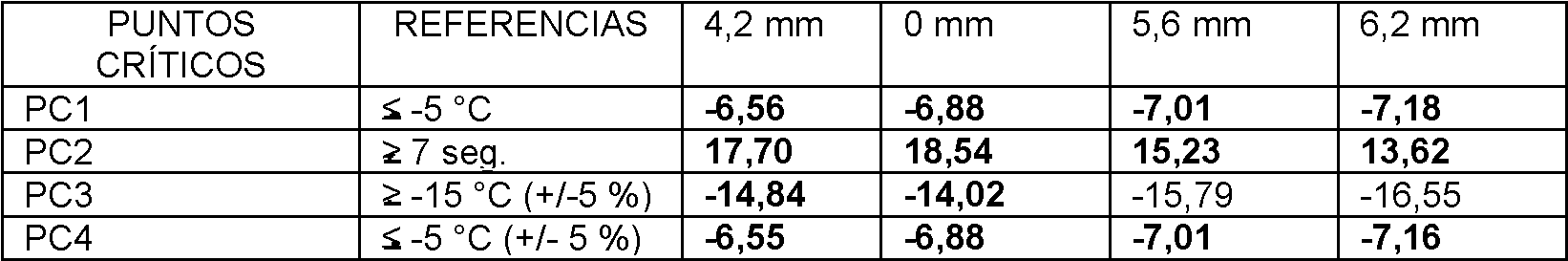
Solo las alturas 0 > H > 4,2 mm, asociadas a una secuencia específica y con un perfil de boquilla específico, permiten satisfacer los valores de referencia.Only heights 0 > H > 4.2 mm, associated with a specific sequence and with a specific nozzle profile, allow the reference values to be met.
Al adaptar la secuencia, o la forma de la boquilla 1, o el diámetro del canal del chorro de pulverización, es posible considerar que un intervalo de alturas comprendido entre 0 y 10 mm, y preferentemente menor o igual a 6 mm, permite obtener un efecto criogénico conforme a los valores de la curva de referencia.By adapting the sequence, or the shape of the nozzle 1, or the diameter of the spray jet channel, it is possible to consider that a range of heights between 0 and 10 mm, and preferably less than or equal to 6 mm, makes it possible to obtain a cryogenic effect according to the values of the reference curve.
Prueba 2 - influencia de la distancia (d) entre la salida del chorro de pulverización y la zona de destino en las curvas de temperatura Test 2 - influence of the distance (d) between the spray jet outlet and the target area on the temperature curves
El objetivo de esta prueba es realizar diferentes medidas de las temperaturas en función del tiempo al variar la distancia (D) entre la salida del chorro de pulverización y el objetivo entre 25 mm y 65 mm.The objective of this test is to make different temperature measurements as a function of time by varying the distance (D) between the spray jet outlet and the target between 25 mm and 65 mm.
Las observaciones son las siguientes. Las distancias cortas (D), y en particular las inferiores a 45 mm, no permiten que el fluido criogénico se expanda satisfactoriamente. Esta situación induce perturbaciones en las mediciones realizadas, debido a que se forman gotitas de fluido (líquido) en el objetivo. Las curvas de temperatura obtenidas tienen oscilaciones de amplitud muy grandes correspondientes entonces a proyecciones del líquido. Para una curva dada, no se satisface ninguno de los valores de referencia de los parámetros (los valores conformes se establecen en negrita).The observations are the following. Short distances (D), and in particular those less than 45 mm, do not allow the cryogenic fluid to expand satisfactorily. This situation induces disturbances in the measurements made, due to the formation of droplets of fluid (liquid) on the target. The temperature curves obtained have very large amplitude oscillations corresponding then to projections of the liquid. for a curve given, none of the parameter reference values are satisfied (conforming values are set in bold).
Tabla 2 - Valores de los parámetros de la curva de referencia para diferentes distancias D (25 mm < D < 40 mm). Table 2 - Values of the parameters of the reference curve for different distances D (25 mm < D < 40 mm).

Las grandes distancias (D), particularmente mayores o iguales a 45 mm, permiten que el gas se expanda y ejerza su potencial criogénico sin formar gotas, que sin embargo disminuyen este potencial al alejarse del objetivo. Para la mayoría de las distancias probadas, los valores de los parámetros de la curva de referencia no se cumplen (valores conformes establecidos en verde), excepto para las curvas correspondientes a las distancias D = 45 mm y D = 55 mm.Large distances (D), particularly greater than or equal to 45 mm, allow the gas to expand and exert its cryogenic potential without forming droplets, which however decrease this potential as they move away from the target. For most of the distances tested, the reference curve parameter values are not met (compliant values set to green), except for curves corresponding to distances D = 45 mm and D = 55 mm.
Tabla 3 - Valores de los parámetros de la curva de referencia para diferentes distancias D (45 mm < D < 65 mm) Table 3 - Values of the parameters of the reference curve for different distances D (45 mm < D < 65 mm)

En consecuencia, solo las distancias D = 45 mm y D = 55 mm que separan la salida del chorro de pulverización del objetivo, asociadas a una secuencia de pulverización específica y a un chorro de pulverización específico, permiten satisfacer estos valores.Consequently, only the distances D = 45 mm and D = 55 mm separating the spray jet exit from the target, associated with a specific spray sequence and a specific spray jet, allow these values to be satisfied.
Así, al adaptar la secuencia o el diámetro del canal de la barra de pulverización, se considera que un intervalo de distancias (D) comprendido entre 35 mm y 55 mm permite obtener un efecto criogénico conforme a los valores de los parámetros de la curva de referencia.Thus, when adapting the sequence or the diameter of the spray bar channel, it is considered that a range of distances (D) comprised between 35 mm and 55 mm allows a cryogenic effect to be obtained according to the values of the parameters of the curve of reference.
Prueba 3 - influencia de las áreas superficiales de abertura de la boquilla en las curvas de temperatura Test 3 - influence of nozzle opening surface areas on temperature curves
El objetivo de esta prueba es realizar diferentes medidas de temperatura en función del tiempo al variar el área superficial (S) de las hendiduras 10 del cuerpo 12 de la boquilla 1 y variar así, en dirección horizontal o vertical, la superficie de intercambio con el aire ambiental lo que contribuye a la expansión del gas y al refuerzo del flujo laminar.The objective of this test is to carry out different temperature measurements as a function of time by varying the surface area (S) of the slits 10 of the body 12 of the nozzle 1 and thus varying, in the horizontal or vertical direction, the exchange surface with the ambient air which contributes to the expansion of the gas and the reinforcement of the laminar flow.
Una modificación vertical consiste en reducir más o menos la altura de las hendiduras lo que reduce al mismo tiempo su superficie de intercambio, con respecto a una boquilla de referencia que tiene un área superficial de abertura total de 2160 mm2, en la dirección de la salida del gas hacia el objetivo. Una modificación horizontal consiste en reducir más o menos el ancho de las hendiduras, es decir, cerrarlas perpendicularmente a la dirección de salida del gas hacia el objetivo.A vertical modification consists of reducing more or less the height of the slits which at the same time reduces their exchange surface, with respect to a reference nozzle that has a total opening surface area of 2160 mm2, in the direction of the outlet. of the gas towards the target. A horizontal modification consists of more or less reducing the width of the slits, that is, closing them perpendicular to the direction of the gas exit towards the target.
Las observaciones son las siguientes. El cuerpo 12 de la boquilla 1 que tiene hendiduras 10 en la configuración específica de la invención y como ilustran las figuras, permite obtener una expansión completa del gas y un aprovechamiento máximo de su potencial criogénico.The observations are the following. The body 12 of the nozzle 1 that has slits 10 in the specific configuration of the invention and as illustrated in the figures, allows a complete expansion of the gas to be obtained and maximum use of its cryogenic potential.
Por otra parte, el cierre total de la boquilla genera una curva que no se ajusta a la curva de referencia, debido a que la expansión del gas es imposible debido a la ausencia de equilibrio, en un tiempo dado, de la presión del gas con la presión atmosférica ambiental.On the other hand, the total closure of the nozzle generates a curve that does not fit the reference curve, since the expansion of the gas is impossible due to the lack of equilibrium, in a given time, of the pressure of the gas with ambient atmospheric pressure.
Tabla 4 - Valores de los parámetros de las curvas con un cuerpo de boquilla sin aberturas (0 % de apertura) y un cuerpo de boquilla con 9 hendiduras con un área superficial de abertura total de 2160 mm2 (100 % de apertura). Table 4 - Values of the parameters of the curves with a nozzle body without openings (0% opening) and a nozzle body with 9 slits with a total opening surface area of 2160 mm2 (100% opening).

Una primera observación es que, independientemente de la secuencia, la conformación del chorro de pulverización (y por tanto el caudal), la cantidad de gas administrado, la forma de la boquilla y un área superficial de abertura total de esta última de al menos 1080 mm2 permite que todo el gas se expanda y elimine la totalidad de su potencial criogénico.A first observation is that, regardless of the sequence, the shape of the spray jet (and therefore the flow rate), the amount of gas administered, the shape of the nozzle and a total opening surface area of the latter of at least 1080 mm2 allows all of the gas to expand and remove all of its cryogenic potential.
Una segunda observación es que cuanto menor es el porcentaje de apertura, más se desvían las curvas de las curvas de referencia y de los valores de sus parámetros.A second observation is that the lower the opening percentage, the more the curves deviate from the reference curves and their parameter values.
Tabla 5 - Valores de los parámetros de las curvas para diferentes modos de apertura vertical de las hendiduras de la boquilla. Table 5 - Values of the parameters of the curves for different modes of vertical opening of the nozzle slits.

Tabla 6 - Valores de los parámetros de las curvas para diferentes modos de apertura horizontal de las hendiduras de la boquilla. Table 6 - Values of the parameters of the curves for different modes of horizontal opening of the nozzle slits.

Así se observa que el impacto en las curvas de la apertura de las hendiduras del cuerpo de la boquilla es diferente, para el mismo porcentaje, según se trate de una apertura vertical u horizontal.Thus, it can be seen that the impact on the curves of the opening of the slits of the nozzle body is different, for the same percentage, depending on whether it is a vertical or horizontal opening.
Tabla 7 - Valores de los parámetros de las curvas para un modo de apertura del 50 % horizontal (denotado h) y del 50 % vertical (denotado v) de la boquilla. Table 7 - Values of the parameters of the curves for an opening mode of 50% horizontal (denoted h) and 50% vertical (denoted v) of the nozzle.

La experiencia demuestra que para dos áreas superficiales idénticas (cada una de 1080 mm2), las curvas de temperatura y sus parámetros son diferentes en función de si la apertura se realiza en sentido vertical u horizontal. Experience shows that for two identical surface areas (each 1080 mm2), the temperature curves and their parameters are different depending on whether the opening is done vertically or horizontally.
Al adaptar la secuencia, o el diámetro del canal del chorro de pulverización, es posible considerar que una apertura total mínima de 1080 mm2 es necesario para garantizar un efecto criogénico conforme al de las curvas de referencia. By adapting the sequence, or the diameter of the spray jet channel, it is possible to consider that a minimum total opening of 1080 mm2 is necessary to guarantee a cryogenic effect in accordance with that of the reference curves.
Claims (10)
Applications Claiming Priority (2)
| Application Number | Priority Date | Filing Date | Title |
|---|---|---|---|
| FR1771438A FR3076200B1 (en) | 2017-12-28 | 2017-12-28 | APPLICATION NOZZLE FOR DEVICE FOR THE DERMO-COSMETIC TREATMENT OF CUTANEOUS BROWN SPOTS BY CYTO-SELECTIVE CRYOTHERAPY |
| PCT/EP2018/097051 WO2019129827A1 (en) | 2017-12-28 | 2018-12-27 | Application nozzle for a device for the dermo-cosmetic treatment of brown spots by means of cyto-selective cryotherapy |
Publications (1)
| Publication Number | Publication Date |
|---|---|
| ES2902189T3 true ES2902189T3 (en) | 2022-03-25 |
Family
ID=62017456
Family Applications (1)
| Application Number | Title | Priority Date | Filing Date |
|---|---|---|---|
| ES18833673T Active ES2902189T3 (en) | 2017-12-28 | 2018-12-27 | Application nozzle for dermocosmetic treatment device for brown skin spots by cytoselective cryotherapy |
Country Status (12)
| Country | Link |
|---|---|
| US (1) | US11589911B2 (en) |
| EP (1) | EP3731770B1 (en) |
| JP (2) | JP2021508585A (en) |
| AU (1) | AU2018397332A1 (en) |
| BR (1) | BR112020013173A2 (en) |
| CA (1) | CA3086608A1 (en) |
| ES (1) | ES2902189T3 (en) |
| FR (1) | FR3076200B1 (en) |
| MX (1) | MX2020006867A (en) |
| PL (1) | PL3731770T3 (en) |
| PT (1) | PT3731770T (en) |
| WO (1) | WO2019129827A1 (en) |
Families Citing this family (2)
| Publication number | Priority date | Publication date | Assignee | Title |
|---|---|---|---|---|
| FR3120792B1 (en) | 2021-03-18 | 2024-03-22 | Cryonove Pharma | Cosmetic composition intended for the treatment of skin hyperpigmentation and treatment method using said composition |
| US20230172682A1 (en) * | 2021-12-07 | 2023-06-08 | Abc-Presents, Llc. | Discrete Cryosurgical Primary-Device |
Family Cites Families (12)
| Publication number | Priority date | Publication date | Assignee | Title |
|---|---|---|---|---|
| AUPM333394A0 (en) * | 1994-01-13 | 1994-02-03 | Meyer, David Jeffrey | Improved flow conditioners for fire fighting nozzles |
| FR2815246B1 (en) * | 2000-10-13 | 2003-01-24 | Cryonic Medical | AUTONOMOUS AND PORTABLE CRYOTHERAPY APPARATUS FOR GENERAL PUBLIC USE |
| FR2885539B1 (en) * | 2005-04-28 | 2008-01-25 | Persee Medica | DEVICE FOR APPLYING A FLUID TO AN AREA TO BE TREATED COMPRISING AN IMPROVED EJECTION NOZZLE |
| WO2007005523A2 (en) * | 2005-06-30 | 2007-01-11 | Stc Consulting, Llc | Method and apparatus for cryogenically treating lesions on biological tissue |
| FR2913960B1 (en) * | 2007-03-20 | 2009-07-03 | Persee Medica Soc Par Actions | DEVICE FOR DISPENSING AND DOSING A FLUID COMPRISING FLUID MEANS FOR CONTROLLING THE TIME OF DISTRIBUTION OF SAID FLUID |
| US20090312693A1 (en) * | 2008-06-13 | 2009-12-17 | Vytronus, Inc. | System and method for delivering energy to tissue |
| US20150066005A1 (en) * | 2013-08-28 | 2015-03-05 | Csa Medical, Inc. | Cryospray catheters |
| EP2952179A1 (en) * | 2014-06-05 | 2015-12-09 | Medical Brands Research B.V. | Treatment of a skin lesion |
| US10625280B2 (en) * | 2014-10-06 | 2020-04-21 | Tel Fsi, Inc. | Apparatus for spraying cryogenic fluids |
| EP3045132A1 (en) * | 2015-01-13 | 2016-07-20 | Starpharm | Cosmetic treatment of brown skin stains |
| US20180345300A1 (en) * | 2017-05-31 | 2018-12-06 | Nike, Inc. | Air Masking Nozzle |
| WO2019006027A1 (en) * | 2017-06-30 | 2019-01-03 | R2 Dermatology, Inc. | Dermatological cryospray devices having linear array of nozzles and methods of use |
-
2017
- 2017-12-28 FR FR1771438A patent/FR3076200B1/en active Active
-
2018
- 2018-12-27 ES ES18833673T patent/ES2902189T3/en active Active
- 2018-12-27 EP EP18833673.9A patent/EP3731770B1/en active Active
- 2018-12-27 WO PCT/EP2018/097051 patent/WO2019129827A1/en unknown
- 2018-12-27 MX MX2020006867A patent/MX2020006867A/en unknown
- 2018-12-27 BR BR112020013173-3A patent/BR112020013173A2/en unknown
- 2018-12-27 CA CA3086608A patent/CA3086608A1/en active Pending
- 2018-12-27 AU AU2018397332A patent/AU2018397332A1/en active Pending
- 2018-12-27 PL PL18833673T patent/PL3731770T3/en unknown
- 2018-12-27 US US16/958,503 patent/US11589911B2/en active Active
- 2018-12-27 PT PT188336739T patent/PT3731770T/en unknown
- 2018-12-27 JP JP2020555308A patent/JP2021508585A/en active Pending
-
2023
- 2023-05-15 JP JP2023080135A patent/JP2023096008A/en active Pending
Also Published As
| Publication number | Publication date |
|---|---|
| FR3076200A1 (en) | 2019-07-05 |
| BR112020013173A2 (en) | 2020-12-01 |
| JP2023096008A (en) | 2023-07-06 |
| EP3731770A1 (en) | 2020-11-04 |
| PT3731770T (en) | 2021-12-27 |
| JP2021508585A (en) | 2021-03-11 |
| CA3086608A1 (en) | 2019-07-04 |
| FR3076200B1 (en) | 2023-04-14 |
| RU2020123875A (en) | 2022-01-28 |
| AU2018397332A1 (en) | 2020-08-06 |
| PL3731770T3 (en) | 2022-02-21 |
| US20210059738A1 (en) | 2021-03-04 |
| US11589911B2 (en) | 2023-02-28 |
| EP3731770B1 (en) | 2021-10-13 |
| WO2019129827A1 (en) | 2019-07-04 |
| RU2020123875A3 (en) | 2022-04-25 |
| MX2020006867A (en) | 2020-09-14 |
Similar Documents
| Publication | Publication Date | Title |
|---|---|---|
| ES2902189T3 (en) | Application nozzle for dermocosmetic treatment device for brown skin spots by cytoselective cryotherapy | |
| ES2633273T3 (en) | Foam dispenser | |
| ES2446382T7 (en) | Steam styling apparatus | |
| ES2663686T3 (en) | Controlled nucleation during the freeze-drying cycle freeze operation using distribution of ice crystals at differential pressure from condensed freezing | |
| ES2392987T3 (en) | Fire extinguisher | |
| ES2364194T3 (en) | DEVICE, ASSEMBLY AND PROCEDURE FOR THE CRYOTHERAPY OF A FABRIC. | |
| ES2248926T3 (en) | FIRE EXTINGUISHING DEVICE. | |
| ES2378180T3 (en) | Device to moisten a glass | |
| ES2327730T3 (en) | SPRAY AND SPRAY HEAD WITH A SPRAY HEAD OF THIS TYPE. | |
| AR059254A1 (en) | COOLING TOWER | |
| ES2562449T3 (en) | Coating device | |
| ES2287147T3 (en) | GAS CONDENSER. | |
| ES2719827T3 (en) | Lining for cryogenic treatment systems | |
| ES2252086T3 (en) | NEEDLE SYRINGE PROVIDED WITH A CONSTANT SECTION EJECTION TUBE. | |
| BR112020001098A2 (en) | dispensing system for use in cryogenic skin treatment and cosmetic skin treatment method | |
| ES2230870T3 (en) | METHOD FOR MANUFACTURING SNOW FOR INSECT CONTROL AND DEVICE FOR YOUR PRACTICE. | |
| CN104819174A (en) | Head for bladeless fan and bladeless fan with head | |
| ES2799600T3 (en) | Controlled nucleation during freeze-drying cycle freeze operation using differential pressure ice crystal distribution from frozen condensate | |
| Sánchez et al. | Observational analysis of handball shot in the counterattack phase of the national teams finalists in 2015 Qatar world handball cup | |
| RU2781078C2 (en) | Application nozzle of device for dermal-cosmetic treatment of dark spots on skin, using cyto-selective cryotherapy | |
| ES2774059T3 (en) | Device and procedure for the vertical transport of oriented molded parts | |
| RU164232U1 (en) | WATER CURTAIN NOZZLE | |
| BR112017028176B1 (en) | NOZZLE ARRANGEMENT FOR A SPRAYING AND DISPENSER HEAD FOR DISPENSING A FLUID AND USE OF SUCH NOZZLE ARRANGEMENT | |
| ES2620509T3 (en) | Device for producing coatings on containers | |
| RU186592U1 (en) | FOAM GENERATOR |