ES2766529T3 - Double-sided thick film heating element with high thermal conductivity - Google Patents
Double-sided thick film heating element with high thermal conductivity Download PDFInfo
- Publication number
- ES2766529T3 ES2766529T3 ES16883017T ES16883017T ES2766529T3 ES 2766529 T3 ES2766529 T3 ES 2766529T3 ES 16883017 T ES16883017 T ES 16883017T ES 16883017 T ES16883017 T ES 16883017T ES 2766529 T3 ES2766529 T3 ES 2766529T3
- Authority
- ES
- Spain
- Prior art keywords
- thick film
- support
- film coating
- heating
- covering layer
- Prior art date
- Legal status (The legal status is an assumption and is not a legal conclusion. Google has not performed a legal analysis and makes no representation as to the accuracy of the status listed.)
- Active
Links
Classifications
-
- H—ELECTRICITY
- H05—ELECTRIC TECHNIQUES NOT OTHERWISE PROVIDED FOR
- H05B—ELECTRIC HEATING; ELECTRIC LIGHT SOURCES NOT OTHERWISE PROVIDED FOR; CIRCUIT ARRANGEMENTS FOR ELECTRIC LIGHT SOURCES, IN GENERAL
- H05B3/00—Ohmic-resistance heating
- H05B3/20—Heating elements having extended surface area substantially in a two-dimensional plane, e.g. plate-heater
- H05B3/22—Heating elements having extended surface area substantially in a two-dimensional plane, e.g. plate-heater non-flexible
- H05B3/26—Heating elements having extended surface area substantially in a two-dimensional plane, e.g. plate-heater non-flexible heating conductor mounted on insulating base
- H05B3/265—Heating elements having extended surface area substantially in a two-dimensional plane, e.g. plate-heater non-flexible heating conductor mounted on insulating base the insulating base being an inorganic material, e.g. ceramic
-
- H—ELECTRICITY
- H05—ELECTRIC TECHNIQUES NOT OTHERWISE PROVIDED FOR
- H05B—ELECTRIC HEATING; ELECTRIC LIGHT SOURCES NOT OTHERWISE PROVIDED FOR; CIRCUIT ARRANGEMENTS FOR ELECTRIC LIGHT SOURCES, IN GENERAL
- H05B3/00—Ohmic-resistance heating
- H05B3/10—Heater elements characterised by the composition or nature of the materials or by the arrangement of the conductor
- H05B3/18—Heater elements characterised by the composition or nature of the materials or by the arrangement of the conductor the conductor being embedded in an insulating material
-
- H—ELECTRICITY
- H05—ELECTRIC TECHNIQUES NOT OTHERWISE PROVIDED FOR
- H05B—ELECTRIC HEATING; ELECTRIC LIGHT SOURCES NOT OTHERWISE PROVIDED FOR; CIRCUIT ARRANGEMENTS FOR ELECTRIC LIGHT SOURCES, IN GENERAL
- H05B3/00—Ohmic-resistance heating
- H05B3/02—Details
- H05B3/06—Heater elements structurally combined with coupling elements or holders
-
- H—ELECTRICITY
- H05—ELECTRIC TECHNIQUES NOT OTHERWISE PROVIDED FOR
- H05B—ELECTRIC HEATING; ELECTRIC LIGHT SOURCES NOT OTHERWISE PROVIDED FOR; CIRCUIT ARRANGEMENTS FOR ELECTRIC LIGHT SOURCES, IN GENERAL
- H05B3/00—Ohmic-resistance heating
- H05B3/10—Heater elements characterised by the composition or nature of the materials or by the arrangement of the conductor
- H05B3/12—Heater elements characterised by the composition or nature of the materials or by the arrangement of the conductor characterised by the composition or nature of the conductive material
-
- H—ELECTRICITY
- H05—ELECTRIC TECHNIQUES NOT OTHERWISE PROVIDED FOR
- H05B—ELECTRIC HEATING; ELECTRIC LIGHT SOURCES NOT OTHERWISE PROVIDED FOR; CIRCUIT ARRANGEMENTS FOR ELECTRIC LIGHT SOURCES, IN GENERAL
- H05B3/00—Ohmic-resistance heating
- H05B3/10—Heater elements characterised by the composition or nature of the materials or by the arrangement of the conductor
- H05B3/16—Heater elements characterised by the composition or nature of the materials or by the arrangement of the conductor the conductor being mounted on an insulating base
-
- H—ELECTRICITY
- H05—ELECTRIC TECHNIQUES NOT OTHERWISE PROVIDED FOR
- H05B—ELECTRIC HEATING; ELECTRIC LIGHT SOURCES NOT OTHERWISE PROVIDED FOR; CIRCUIT ARRANGEMENTS FOR ELECTRIC LIGHT SOURCES, IN GENERAL
- H05B3/00—Ohmic-resistance heating
- H05B3/20—Heating elements having extended surface area substantially in a two-dimensional plane, e.g. plate-heater
- H05B3/22—Heating elements having extended surface area substantially in a two-dimensional plane, e.g. plate-heater non-flexible
- H05B3/26—Heating elements having extended surface area substantially in a two-dimensional plane, e.g. plate-heater non-flexible heating conductor mounted on insulating base
- H05B3/267—Heating elements having extended surface area substantially in a two-dimensional plane, e.g. plate-heater non-flexible heating conductor mounted on insulating base the insulating base being an organic material, e.g. plastic
-
- H—ELECTRICITY
- H05—ELECTRIC TECHNIQUES NOT OTHERWISE PROVIDED FOR
- H05B—ELECTRIC HEATING; ELECTRIC LIGHT SOURCES NOT OTHERWISE PROVIDED FOR; CIRCUIT ARRANGEMENTS FOR ELECTRIC LIGHT SOURCES, IN GENERAL
- H05B2203/00—Aspects relating to Ohmic resistive heating covered by group H05B3/00
- H05B2203/013—Heaters using resistive films or coatings
Abstract
Elemento de pelicula gruesa con una alta conductividad termica en dos de sus lados, que comprende un soporte; un recubrimiento de pelicula gruesa depositado en el soporte y una capa de cobertura que cubre el recubrimiento, el recubrimiento de pelicula gruesa es un material de calentamiento, y un modo de 5 calentamiento es el calentamiento electrico, caracterizado por el hecho de que el soporte, el recubrimiento de pelicula gruesa y la capa de cobertura se seleccionan a partir de un material que satisface todas las ecuaciones siguientes:**Fórmula** y**Fórmula** y**Fórmula** donde una formula de calculo para Q1 es:**Fómula** una formula de calculo para Q2 es::**Fómula** una formula de calculo para Q3 es::**Fómula** T2 < TPunto de fusión mínimo de la capa de cobertura; T2 < TPunto de fusión mínimo del soporte; T0 <=25 ºC; donde Q1 representa una tasa de transferencia de calor de la capa de cobertura; Q2 representa una tasa de transferencia de calor del recubrimiento de pelicula gruesa; Q3 representa una tasa de transferencia de calor del soporte; λ1 representa un coeficiente de conductividad termica de la capa de cobertura; λ2 representa un coeficiente de conductividad termica del recubrimiento de pelicula gruesa; λ3 representa un coeficiente de conductividad termica del soporte; A representa, en funcion del caso de calculo, un area de contacto del recubrimiento de pelicula gruesa ya sea con la capa de cobertura o con el soporte; b1 representa un grosor de la capa de cobertura; b2 representa un grosor del recubrimiento de pelicula gruesa; b3 representa un grosor del soporte; T0 representa una temperatura inicial del elemento calefactor de pelicula gruesa antes de comenzar el calentamiento; T1 representa una temperatura superficial de la capa de cobertura medida bajo un estado de calentamiento estable; T2 representa una temperatura de calentamiento del recubrimiento de pelicula gruesa medida bajo dicho estado de calentamiento estable; T3 representa una temperatura superficial del soporte medida en un estado de calentamiento estable;Thick film element with high thermal conductivity on two of its sides, comprising a support; a thick film coating deposited on the support and a covering layer covering the coating, the thick film coating is a heating material, and a heating mode is electric heating, characterized by the fact that the support, The thick film coating and top coat are selected from a material that satisfies all of the following equations: ** Formula ** and ** Formula ** and ** Formula ** where a calculation formula for Q1 is: ** Formula ** a calculation formula for Q2 is :: ** Formula ** a calculation formula for Q3 is :: ** Formula ** T2 <T Minimum melting point of the covering layer; T2 <T Minimum melting point of the support; T0 <= 25 ° C; where Q1 represents a heat transfer rate of the cover layer; Q2 represents a heat transfer rate of the thick film coating; Q3 represents a heat transfer rate of the support; λ1 represents a coefficient of thermal conductivity of the cover layer; λ2 represents a coefficient of thermal conductivity of the thick film coating; λ3 represents a coefficient of thermal conductivity of the support; A represents, depending on the calculation case, a contact area of the thick film coating either with the covering layer or with the support; b1 represents a thickness of the cover layer; b2 represents a thickness of the thick film coating; b3 represents a thickness of the support; T0 represents an initial temperature of the thick film heating element before heating begins; T1 represents a surface temperature of the cover layer measured under a stable heating state; T2 represents a heating temperature of the thick film coating measured under said stable heating state; T3 represents a surface temperature of the support measured in a stable heating state;
Description
DESCRIPCIÓNDESCRIPTION
Elemento calefactor de película gruesa de doble cara con una alta conductividad térmicaDouble-sided thick film heating element with high thermal conductivity
CAMPO DE LA INVENCIÓNFIELD OF THE INVENTION
[0001] La presente invención se refiere al campo de las películas gruesas y, más particularmente, a un elemento de película gruesa con una alta conductividad térmica en sus dos lados.[0001] The present invention relates to the field of thick films and, more particularly, to a thick film element with high thermal conductivity on its two sides.
ANTECEDENTES DE LA INVENCIÓNBACKGROUND OF THE INVENTION
[0002] Elementos calefactores de película gruesa se refiere a elementos calefactores que se hacen fabricando materiales exotérmicos en unas películas gruesas de sustrato y proporcionando electricidad para generar calor. Los métodos de calentamiento convencionales incluyen el calentamiento eléctrico, el calentamiento con tubos y el calentamiento PTC. Un elemento calefactor de tubo calentado eléctricamente se sirve de un tubo metálico como la carcasa externa y distribuye aleación de níquel-cromo o hierro-cromo en espiral en él para formar bandas calefactoras; a continuación, el espacio libre se llena con escoria de magnesita que tiene una conductividad térmica y una capacidad aislante excelentes y se sella con gel de sílice en ambos extremos del tubo. El método de calentamiento PTC se sirve de cerámica como el material exotérmico. Tanto el calentamiento de tubo calentado eléctricamente como el calentamiento PTC producen el calentamiento indirectamente con un bajo rendimiento térmico y son estructuralmente enormes y pesados. Además, tomando en consideración la protección ambiental, los calentadores que se sirven de estos dos tipos de métodos de calentamiento se manchan fácilmente después de un calentamiento calentando reiterado y su limpieza no es fácil. Adicionalmente, los calentadores PTC contienen plomo y otras sustancias peligrosas y se oxidan fácilmente, provocando una atenuación de la potencia y una vida útil corta.[0002] Thick film heating elements refers to heating elements that are made by making exothermic materials in thick substrate films and providing electricity to generate heat. Conventional heating methods include electric heating, tube heating, and PTC heating. An electrically heated tube heating element uses a metal tube as the outer shell and distributes nickel-chrome or iron-chrome alloy spirally into it to form heating bands; The gap is then filled with magnesite slag that has excellent thermal conductivity and insulating ability and is sealed with silica gel at both ends of the tube. The PTC heating method uses ceramic as the exothermic material. Both electrically heated tube heating and PTC heating produce indirect heating with low thermal performance and are structurally huge and heavy. In addition, taking environmental protection into consideration, heaters using these two types of heating methods easily stain after repeated heating heating and cleaning is not easy. Additionally, PTC heaters contain lead and other hazardous substances and are easily oxidized, causing a loss of power and a short service life.
[0003] La aplicación china CN 102833894 A divulga un tubo calentamiento de aleación de aluminio que emplea calentamiento de película gruesa, que comprende un cuerpo de tubo de calentamiento y una placa de calentamiento de película gruesa. Una ranura de inserción, cuya dirección de profundidad se extiende radialmente hacia el interior, está dispuesta en un lado del cuerpo del tubo de calentamiento. La placa de calentamiento de película gruesa está situada en la ranura de inserción. El cuerpo de tubo de calentamiento tiene agujeros pasantes, cuya dirección de longitud se extiende axialmente hacia adentro a lo largo del cuerpo de tubo de calentamiento, dispuestos a ambos lados de la ranura de inserción. En el tubo de calentamiento de aleación de aluminio, el circuito de calentamiento de película gruesa en la placa de circuito impreso de película gruesa está impreso en el sustrato de cerámica o un sustrato de otro material aislante. Además, la placa de circuito impreso de película gruesa está recubierta con una capa más de medio aislante; por lo tanto, la superficie de toda la placa de circuito impreso de película gruesa es aislante.[0003] Chinese application CN 102833894 A discloses an aluminum alloy heating tube employing thick film heating, comprising a heating tube body and a thick film heating plate. An insertion groove, the depth direction of which extends radially inward, is arranged on one side of the body of the heating tube. The thick film heating plate is located in the insertion slot. The heating tube body has through holes, the length direction of which extends axially inward along the heating tube body, arranged on both sides of the insertion slot. In the aluminum alloy heating tube, the thick film heating circuit on the thick film printed circuit board is printed on the ceramic substrate or a substrate of other insulating material. In addition, the thick film printed circuit board is coated with one more layer of insulating medium; therefore, the surface of the entire thick film printed circuit board is insulating.
[0004] La aplicación china CN 101778501 A divulga un ensamblaje calefactor de película gruesa con función de protección de quemado en seco, que comprende un calefactor de película gruesa para el calentamiento eléctrico, un soporte de conexión eléctrica montado sobre el calefactor de película gruesa para conectar el calefactor de película gruesa con componentes externos y un protector de quemado en seco montado sobre el calefactor de película gruesa. El soporte de conexión eléctrica y el protector de quemado en seco forman los componentes enteros y el protector de quemado en seco contiene al menos un protector a prueba de quemado en seco eléctrico conectado eléctricamente al circuito de control y un protector a prueba de quemado en seco mecánico.[0004] Chinese application CN 101778501 A discloses a thick film heater assembly with dry burn protection function, comprising a thick film heater for electrical heating, an electrical connection bracket mounted on the thick film heater for connect the thick film heater to external components and a dry burn protector mounted on the thick film heater. The electrical connection bracket and the dry burn protector form the entire components and the dry burn protector contains at least one electrical dry burn proof protector electrically connected to the control circuit and a dry burn proof protector mechanic.
[0005] Aunque los elementos calefactores existentes se han aplicado gradualmente al campo de los aparatos domésticos eléctricos, los cuerpos de calentamiento del elemento de película gruesa mencionados anteriormente se fijan sobre los aparatos eléctricos y actualmente existen pocos componentes independientes. A día de hoy, ninguno de los elementos calefactores existentes tiene una alta conductividad térmica de doble cara y no se ha aplicado ningún elemento calefactor de película gruesa de doble cara a la vida diaria y a la producción industrial para hacer realidad la función de calentamiento uniforme en los dos lados del elemento.[0005] Although existing heating elements have been gradually applied to the field of electrical household appliances, the thick film element heating bodies mentioned above are affixed to electrical appliances and there are currently few independent components. As of today, none of the existing heating elements have high double-sided thermal conductivity and no double-sided thick film heating element has been applied to daily life and industrial production to realize the uniform heating function in the two sides of the element.
[0006] La patente DE 102014108356 A1 divulga un elemento calefactor plano que comprende una estructura PTC resistiva que está dispuesta en una región superficial definida de una primera superficie (4) de un sustrato de soporte, donde contactos de conexión eléctrica para la conexión con una fuente de tensión eléctrica se asocian con la estructura PTC resistiva, donde la estructura PTC resistiva que parte de los dos contactos de conexión eléctrica tiene al menos un rastro conductor interno y un rastro conductor externo conectado paralelo, donde el rastro conductor interno tiene una mayor resistencia que el rastro conductor externo y donde las resistencias del rastro conductor interno y el rastro conductor externo están dimensionadas de tal manera que, al aplicar una tensión, está presente una distribución de temperatura esencialmente uniforme en la región superficial definida.[0006] Patent DE 102014108356 A1 discloses a flat heating element comprising a resistive PTC structure that is arranged in a defined surface region of a first surface (4) of a support substrate, where electrical connection contacts for connection with a Electrical voltage source are associated with the resistive PTC structure, where the resistive PTC structure that part of the two electrical connection contacts has at least one internal conductor trace and a parallel connected external conductor trace, where the internal conductor trace has a higher resistance that the outer conducting trace and where the resistors of the inner conducting trace and the outer conducting trace are dimensioned such that, upon application of a voltage, an essentially uniform temperature distribution is present in the defined surface region.
[0007] La patente EP 0958712 A1 divulga un elemento calefactor de inmersión. El elemento calefactor de inmersión comprende un primer y un segundo sustrato conductor térmico que definen superficies superior e inferior del elemento calefactor. Una capa eléctricamente aislante se proporciona en un lado de cada sustrato, y los dos sustratos se montan junto con las capas aislantes el uno frente al otro y con una vía de calentamiento resistiva intercalada entre las capas aislantes. Esta estructura evita la necesidad de una capa protectora aislante y gruesa en la vía de calentamiento.[0007] Patent EP 0958712 A1 discloses an immersion heating element. The immersion heating element comprises a first and a second thermally conductive substrate defining upper and lower surfaces of the heating element. An electrically insulating layer is provided on one side of each substrate, and the two substrates are mounted together with the insulating layers facing each other and with a resistive heating path sandwiched between the insulating layers. This structure avoids the need for a thick insulating protective layer on the heating path.
[0008] La patente US 5793929 A1 divulga un calefactor de inmersión. El calefactor de inmersión tiene una placa de soporte sobre la que se proporciona un elemento calefactor eléctrico en forma de una vía conductora de circuito impreso. El elemento dispone de una porción que permite fijarlo en relación directa con una unidad de control para proporcionar conexión eléctrica, térmica y mecánica directa a dicha unidad. Esto permite que la unidad de control opere de la misma forma que una unidad de control conectada a un calefactor de inmersión convencional.[0008] US patent 5793929 A1 discloses an immersion heater. The immersion heater has a support plate on which an electrical heating element in the form of a conductive printed circuit path is provided. The element has a portion that allows it to be fixed in direct relation with a control unit to provide direct electrical, thermal and mechanical connection to said unit. This allows the control unit to operate in the same way as a control unit connected to a conventional immersion heater.
RESUMEN DE LA INVENCIÓNSUMMARY OF THE INVENTION
[0009] Para resolver estos problemas mencionados previamente, la presente invención proporciona un elemento de película gruesa con una alta conductividad térmica en sus dos lados con las ventajas de un volumen pequeño, una alta eficiencia, respeto al medioambiente, alto rendimiento en seguridad y una larga durabilidad servicio.[0009] In order to solve these previously mentioned problems, the present invention provides a thick film element with a high thermal conductivity on both sides with the advantages of small volume, high efficiency, respect for the environment, high safety performance and a long service durability.
[0010] El concepto de película gruesa en la presente invención es un término comparativo con respecto a las películas finas. Una película gruesa es una capa de película con un grosor que varía de varios micrómetros a decenas de micrómetros formada mediante impresión y sinterización en un soporte; el material usado para producir la capa de película se conoce como película gruesa, y el recubrimiento hecho con la película gruesa se llama recubrimiento de película gruesa. El elemento calefactor de película gruesa tiene las ventajas de una alta densidad de potencia, una alta velocidad de calentamiento, una alta temperatura de funcionamiento, una rápida tasa de generación de calor, una gran fuerza mecánica, un pequeño volumen, una instalación fácil, un campo de temperatura de calentamiento uniforme, una larga vida útil, ahorro de energía y respeto al medioambiente, y rendimiento en seguridad excelente.[0010] The concept of thick film in the present invention is a comparative term with respect to thin films. A thick film is a layer of film with a thickness ranging from several micrometers to tens of micrometers formed by printing and sintering on a support; the material used to produce the film layer is known as thick film, and the coating made from the thick film is called the thick film coating. Thick film heating element has the advantages of high power density, high heating speed, high operating temperature, fast rate of heat generation, high mechanical strength, small volume, easy installation, a Uniform heating temperature field, long service life, energy saving and environmental friendly, and excellent safety performance.
[0011] El elemento de película gruesa con una alta conductividad térmica en sus dos lados de la presente invención comprende un soporte, un recubrimiento de película gruesa depositado en el soporte y una capa de cobertura que cubre el recubrimiento. El recubrimiento de película gruesa es un material de calentamiento, y el modo de calentamiento es el calentamiento eléctrico. Según la invención, el soporte, el recubrimiento de película gruesa y la capa de cobertura se seleccionan a partir de un material que cumple cada una de las siguientes ecuaciones:[0011] The thick film element with high thermal conductivity on its two sides of the present invention comprises a support, a thick film coating deposited on the support and a covering layer covering the coating. Thick film coating is a heating material, and the heating mode is electric heating. According to the invention, the support, the thick film coating and the covering layer are selected from a material that meets each of the following equations:

0.2 — Q í*0.2 - Q í *
yand
Q i=axQ3, Q2=bxQi, Q2= c xQ3;Q i = axQ3, Q2 = bxQi, Q2 = c xQ3;
yand
![]()
![]()
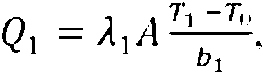
donde la fórmula de cálculo para Q1 es:where the calculation formula for Q1 is:

la fórmula de cálculo para Q2 es:the calculation formula for Q2 is:

la fórmula de cálculo para Q3 es:the calculation formula for Q3 is:

T 2 < T Punto de fusión mínimo de la capa de cobertura; T 2 < T Minimum melting point of the covering layer;
T 2 < TPunto de fusión mínimo del soporte; T 2 < T Minimum melting point of the support;
T o < 25 °C; T or < 25 ° C;
donde Qi representa la tasa de transferencia de calor de la capa de cobertura; Q2 representa la tasa de generación de calor del recubrimiento de película gruesa; Q3 representa la tasa de transferencia de calor del soporte;where Qi represents the heat transfer rate of the covering layer; Q2 represents the heat generation rate of the thick film coating; Q3 represents the heat transfer rate of the support;
Ai representa el coeficiente de conductividad térmica de la capa de cobertura; A2 representa el coeficiente de conductividad térmica del recubrimiento de película gruesa; A3 representa el coeficiente de conductividad térmica del soporte;Ai represents the coefficient of thermal conductivity of the covering layer; A2 represents the coefficient of thermal conductivity of the thick film coating; A3 represents the coefficient of thermal conductivity of the support;
A representa, en función del caso de cálculo, el área de contacto del recubrimiento de película gruesa ya sea con la capa de cobertura o con el soporte;A represents, depending on the calculation case, the contact area of the thick film coating either with the covering layer or with the support;
bi representa el grosor de la capa de cobertura; b2 representa el grosor del recubrimiento de película gruesa; b3 representa el grosor del soporte;bi represents the thickness of the covering layer; b2 represents the thickness of the thick film coating; b3 represents the thickness of the support;
To representa la temperatura inicial del elemento calefactor de película gruesa antes de comenzar a calentar; Ti representa la temperatura superficial de la capa de cobertura medida en un estado de calentamiento estable; T2 representa la temperatura de calentamiento del recubrimiento de película gruesa medida en dicho estado de calentamiento estable; T3 representa la temperatura superficial del soporte medida en dicho estado de calentamiento estable;To represents the initial temperature of the thick film heating element before heating begins; Ti represents the surface temperature of the covering layer measured in a stable heating state; T2 represents the heating temperature of the thick film coating measured in said stable heating state; T3 represents the surface temperature of the support measured in said stable heating state;

b-.>bi, bi< 1 mm. bi>lmm:b -.> bi, bi <1 mm. bi> lmm:
Tpunto de fusión mínimo del soporte > 25 °C Minimum melting point of the support > 25 ° C
[0012] La capa de cobertura es un recubrimiento de capa dieléctrica en el recubrimiento de película gruesa mediante impresión o sinterización y el área de la capa de cobertura es mayor que el del recubrimiento de película gruesa.[0012] The covering layer is a dielectric layer coating on the thick film coating by printing or sintering and the area of the covering layer is larger than that of the thick film coating.
[0013] El soporte es la capa dieléctrica que porta el recubrimiento de película gruesa. El recubrimiento de película gruesa cubre el soporte mediante impresión o sinterización.[0013] The support is the dielectric layer that carries the thick film coating. The thick film coating covers the media by printing or sintering.
[0014] El coeficiente de conductividad térmica se refiere al calor transferido por un material de un metro de grosor que tiene una diferencia de temperatura entre dos superficies laterales de 1 grado (K, °C), a través de un área de un metro cuadrado (1 m2) en un segundo (1 S) en una condición de transferencia de calor estable. La unidad del coeficiente de conductividad térmica es vatio/metro • grado (W/(m • K), y K se puede sustituir por °C).[0014] The coefficient of thermal conductivity refers to the heat transferred by a one meter thick material that has a temperature difference between two 1 degree (K, ° C) side surfaces, through an area of one square meter (1 m2) in one second (1 S) in a stable heat transfer condition. The unit of the coefficient of thermal conductivity is watt / meter • degree (W / (m • K), and K can be replaced by ° C).
[0015] La capa de cobertura, el recubrimiento de película gruesa y el soporte se adhieren cercanamente entre sí en las partes de calentamiento eléctrico de los elementos calefactores de película gruesa y ambos extremos del recubrimiento de película gruesa se conectan a electrodos externos. Cuando se le proporciona electricidad, el recubrimiento de película gruesa se calienta y se vuelve caliente después de que la energía eléctrica se transforme en energía térmica. La tasa de generación de calor del recubrimiento de película gruesa se podría calcular [0015] The covering layer, the thick film coating and the support adhere closely to each other in the electrical heating parts of the thick film heating elements and both ends of the thick film coating are connected to external electrodes. When supplied with electricity, the thick film coating heats up and becomes hot after the electrical energy is transformed into thermal energy. The heat generation rate of the thick film coating could be calculated
Q 2 = * 2A Jkj r íQ 2 = * 2A Jkj r í
mediante 2 según el coeficiente de conductividad térmica, el área de contacto, la temperatura inicial, la temperatura de calentamiento y el grosor del recubrimiento de película gruesa, donde T2 representa la temperatura de calentamiento de la película gruesa.by 2 according to the coefficient of thermal conductivity, the contact area, the initial temperature, the heating temperature and the thickness of the thick film coating, where T2 represents the heating temperature of the thick film.
[0016] La presente invención muestra que los dos lados del elemento de película gruesa tienen una alta conductividad térmica y que la tasa de generación de calor de la capa de cobertura, el recubrimiento de película gruesa y el soporte deberán cumplir los requisitos siguientes:[0016] The present invention shows that the two sides of the thick film element have a high thermal conductivity and that the heat generation rate of the cover layer, the thick film coating and the support should meet the following requirements:
(1) la tasa de transferencia de calor de la capa de cobertura y el soporte debería satisfacer la fórmula siguiente: Q1 = a x Q3, donde 0,1 < a < 150; para aquellos elementos de película gruesa que satisfagan la ecuación anterior, la capa de cobertura y el soporte del elemento calefactor de película gruesa tienen una capacidad de transferencia de calor constante, evitando así un aumento de temperatura demasiado rápido en un lado y un aumento de temperatura demasiado lento en otro lado del elemento de película gruesa y evitando el fenómeno de calentamiento desigual en los dos lados, que no cumpliría el efecto técnico de la presente invención;(1) the heat transfer rate of the cover layer and the support should satisfy the following formula: Q1 = a x Q3, where 0.1 <a <150; For those thick film elements that satisfy the above equation, the cover layer and support of the thick film heating element have a constant heat transfer capability, thus avoiding too rapid temperature rise on one side and temperature rise too slow on the other side of the thick film element and avoiding the uneven heating phenomenon on the two sides, which would not fulfill the technical effect of the present invention;
(2) la tasa de generación de calor del recubrimiento de película gruesa y la tasa de transferencia de calor de la capa de cobertura deberían satisfacer la fórmula siguiente: Q2 s Q1, y Q2 = b x Q1, donde 1 < b < 2500; si la tasa de generación de calor del recubrimiento de película gruesa es mucho mayor que la tasa de transferencia de calor de la capa de cobertura, el calor acumulado de forma continua del recubrimiento de película gruesa no se podría conducir fuera, de manera que la temperatura del recubrimiento de película gruesa sigue subiendo, y cuando la temperatura es superior al punto de fusión mínimo de la capa de cobertura, la capa de cobertura empezará a fundirse o incluso a quemarse, lo que destruiría la estructura de la capa de cobertura o el soporte, destruyendo así los elementos calefactores de película gruesa. (2) the heat generation rate of the thick film coating and the heat transfer rate of the cover layer should satisfy the following formula: Q2 s Q1, and Q2 = bx Q1, where 1 <b <2500; If the heat generation rate of the thick film coating is much higher than the heat transfer rate of the covering layer, the continuously accumulated heat of the thick film coating could not be conducted outside, so that the temperature The thick film coating continues to rise, and when the temperature is above the minimum melting point of the covering layer, the covering layer will start to melt or even burn, destroying the structure of the covering layer or the support , thus destroying the thick film heating elements.
(3) la tasa de generación de calor del recubrimiento de película gruesa y la tasa de transferencia de calor del soporte deberían satisfacer la fórmula siguiente: Q2 s Q3, y Q2 = c x Q3,100 < c < 10000; si la tasa de generación de calor del recubrimiento de película gruesa es mucho mayor que la tasa de transferencia de calor del soporte, el calor acumulado de forma continua del recubrimiento de película gruesa no se podría conducir fuera, de manera que la temperatura del recubrimiento de película gruesa sigue subiendo, y cuando la temperatura es superior al punto de fusión mínimo del soporte, el soporte empezará a fundirse o incluso a quemarse, lo que destruiría la estructura del soporte, destruyendo así los elementos calefactores de película gruesa.(3) the heat generation rate of the thick film coating and the heat transfer rate of the support should satisfy the following formula: Q2 s Q3, and Q2 = c x Q3,100 <c <10,000; If the heat generation rate of the thick film coating is much higher than the heat transfer rate of the support, the continuously accumulated heat of the thick film coating could not be conducted outside, so that the temperature of the Thick film continues to rise, and when the temperature is above the minimum melting point of the support, the support will begin to melt or even burn, which would destroy the structure of the support, thus destroying the thick film heating elements.
(4) la temperatura de calentamiento del recubrimiento de película gruesa no podría ser superior al punto de fusión mínimo de la capa de cobertura o el soporte y debería cumplir los requisitos. T 2 < T punto de fusión mínimo de a capa de cobertura y T 2 < T punto de fusión mínimo del soporte . Debería evitarse una temperatura de calentamiento excesivamente alta para prevenir la destrucción de los elementos calefactores de película gruesa.(4) The heating temperature of the thick film coating could not exceed the minimum melting point of the cover layer or the support and should meet the requirements. T 2 < T minimum melting point of the cover layer and T 2 < T minimum melting point of the support . An excessively high heating temperature should be avoided to prevent destruction of thick film heating elements.
[0017] Cuando se cumplen los requisitos anteriormente mencionados, las tasas de transferencia de calor de la capa de cobertura y el soporte se determinan por las propiedades del material y el elemento calefactor de película Q , = A , A ^ , gruesa. La fórmula para calcular la tasa de transferencia de calor de la capa de cobertura es 1 donde A1 representa el coeficiente de conductividad térmica de la capa de cobertura, donde la unidad es W/m.k, y se determina por las propiedades de los materiales para preparar la capa de cobertura; bi representa el grosor de la capa de cobertura, y se determina por la técnica de preparación y los requisitos de los elementos calefactores de película gruesa; Ti representa la temperatura superficial de la capa de cobertura y se determina por las propiedades de los elementos calefactores de película gruesa.[0017] When the aforementioned requirements are met, the heat transfer rates of the cover layer and the support are determined by the properties of the material and the thick film heating element Q, = A, A ^, thick. The formula for calculating the heat transfer rate of the covering layer is 1 where A1 represents the coefficient of thermal conductivity of the covering layer, where the unit is W / mk, and is determined by the properties of the materials to prepare the covering layer; bi represents the thickness of the covering layer, and is determined by the preparation technique and the requirements of the thick film heating elements; Ti represents the surface temperature of the cover layer and is determined by the properties of thick film heating elements.

[0018] La fórmula para calcular la tasa de transferencia de calor del soporte es Q3 = 3 donde A3 representa el coeficiente de conductividad térmica del soporte, donde la unidad es W/m.k y se determina por las propiedades de los materiales para preparar el soporte; d3 representa el grosor del soporte y se determina por la técnica de preparación y los requisitos de los elementos calefactores de película gruesa; T3 representa la temperatura superficial del soporte y se determina por las propiedades de los elementos calefactores de película gruesa.[0018] The formula to calculate the heat transfer rate of the support is Q3 = 3 where A3 represents the coefficient of thermal conductivity of the support, where the unit is W / mk and is determined by the properties of the materials to prepare the support ; d3 represents the thickness of the support and is determined by the preparation technique and the requirements of the thick film heating elements; T3 represents the surface temperature of the support and is determined by the properties of the thick film heating elements.
[0019] Preferiblemente, el soporte y el recubrimiento de película gruesa están unidos mediante impresión o sinterización, el recubrimiento de película gruesa y la capa de cobertura están unidos por impresión o sinterización.[0019] Preferably, the backing and thick film coating are bonded by printing or sintering, the thick film coating and covering layer are bonded by printing or sintering.
[0020] Preferiblemente, la región entre el soporte y la capa de cobertura sin el recubrimiento de película gruesa está unida mediante impresión o sinterización.[0020] Preferably, the region between the support and the cover layer without the thick film coating is bonded by printing or sintering.
[0021] Preferiblemente, el soporte incluye poliimidas, materiales aislantes orgánicos, materiales aislantes inorgánicos y materiales de cerámica, vitrocerámica, cuarzo, cristal y piedra.[0021] Preferably, the support includes polyimides, organic insulating materials, inorganic insulating materials, and ceramic, glass-ceramic, quartz, glass, and stone materials.
[0022] Preferiblemente, el recubrimiento de película gruesa es uno o más entre plata, platino, paladio, óxido de paladio, oro o materiales de tierras raras.[0022] Preferably, the thick film coating is one or more among silver, platinum, palladium, palladium oxide, gold or rare earth materials.
[0023] Preferiblemente, la capa de cobertura está hecha de uno o más entre poliéster, poliimida o polieterimida (PEI), cerámica, gel de sílice, amianto, micarex.[0023] Preferably, the cover layer is made of one or more of polyester, polyimide or polyetherimide (PEI), ceramic, silica gel, asbestos, micarex.
[0024] Preferiblemente, el área del recubrimiento de película gruesa es inferior o igual al de la capa de cobertura o el soporte.[0024] Preferably, the area of the thick film coating is less than or equal to that of the cover layer or the backing.
[0025] La presente invención proporciona también un uso de los elementos de película gruesa para productos con calentamiento de doble cara.[0025] The present invention also provides a use of thick film elements for products with double-sided heating.
[0026] Los efectos beneficiosos de la presente invención son como sigue:[0026] The beneficial effects of the present invention are as follows:
(1) El elemento de película gruesa de la presente invención tiene una alta conductividad térmica y una tasa de generación de calor uniforme en sus dos lados y muestra una eficiencia de transferencia de calor mejorada. (2) La estructura de tres capas del elemento de película gruesa de la presente invención se podría unir directamente mediante impresión o sinterización y el recubrimiento de película gruesa calentaría la capa de cobertura directamente para mejorar la eficiencia de conducción térmica. De forma adicional, la capa de cobertura de la presente invención cubre el recubrimiento de película gruesa, evitando así el problema de fuga eléctrica cuando se proporciona electricidad al recubrimiento de película gruesa y mejorando el rendimiento en seguridad.(1) The thick film element of the present invention has a high thermal conductivity and a uniform heat generation rate on both sides, and shows improved heat transfer efficiency. (2) The three layer structure of the thick film element of the present invention could be directly bonded by printing or sintering and the thick film coating would heat the covering layer directly to improve the thermal conduction efficiency. Additionally, the cover layer of the present invention covers the thick film coating, thus avoiding the problem of electrical leakage when electricity is provided to the thick film coating and improving safety performance.
(3) El elemento de película gruesa de la presente invención podría aplicarse a productos que requieran una alta conductividad térmica en los dos lados, satisfaciendo la demanda del mercado con respecto a productos de calentamiento multifuncionales. (3) The thick film element of the present invention could be applied to products that require high thermal conductivity on both sides, satisfying the market demand for multifunctional heating products.
(4) El elemento calefactor de película gruesa de la presente invención genera calor mediante el recubrimiento de película gruesa. El grosor del recubrimiento de película gruesa está a nivel micrométrico, generando así calor uniformemente después de que se le haya proporcionado electricidad. El elemento de película gruesa tiene una larga durabilidad de servicio.(4) The thick film heating element of the present invention generates heat by thick film coating. The thickness of the thick film coating is at the micrometer level, thereby generating heat evenly after electricity has been supplied. The thick film element has long service durability.
DESCRIPCIÓN DETALLADA DE LAS FORMAS DE REALIZACIÓN PREFERIDASDETAILED DESCRIPTION OF THE PREFERRED FORMS OF REALIZATION
[0027] La presente invención se describirá a continuación más específicamente con referencia a las formas de realización siguientes. Cabe mencionar que las descripciones siguientes de las formas de realización preferidas de esta invención se presentan aquí únicamente con fines ilustrativos y descriptivos. No se pretende ser exhaustivo o a limitarse a la forma descrita precisa.[0027] The present invention will now be described more specifically with reference to the following embodiments. It should be mentioned that the following descriptions of the preferred embodiments of this invention are presented here for illustrative and descriptive purposes only. It is not intended to be exhaustive or limited to the precise form described.
[0028] La presente invención divulga un elemento de película gruesa con una alta conductividad térmica en sus dos lados de la presente invención, comprende un soporte, un recubrimiento de película gruesa depositado en el soporte y una capa de cobertura que cubre el recubrimiento. El recubrimiento de película gruesa es un material calefactor y el modo de calentamiento es el calentamiento eléctrico. El soporte, el recubrimiento de película gruesa y la capa de cobertura se seleccionan a partir de un material que satisface todas las ecuaciones siguientes:[0028] The present invention discloses a thick film element with a high thermal conductivity on its two sides of the present invention, comprising a support, a thick film coating deposited on the support and a covering layer covering the coating. The thick film coating is a heating material and the heating mode is electric heating. The backing, thick film coating, and topcoat are selected from a material that satisfies all of the following equations:
Q2 — Q 3 Q2 - Q 3
0.2 0.2 — - Q iQ i
yand
Q i=axQ 3, Q2=bxQ !, Q2=cxQ 3;Q i = axQ 3, Q2 = bxQ!, Q2 = cxQ 3;
yand
![]()
![]()
donde, la fórmula de cálculo para Q1 es:where, the calculation formula for Q1 is:

la fórmula de cálculo para Q2 es:the calculation formula for Q2 is:

la fórmula de cálculo para Q3 es:the calculation formula for Q3 is:

T 2 < Tpunto de fusión mínimo de la capa de cobertura; T 2 < Minimum melting point of the covering layer;
T 2 < Tpunto de fusión mínimo del soporte; T 2 < Minimum melting point of the support;
T o < 25 °C; T or < 25 ° C;
b2 representa el grosor del recubrimiento de película gruesa, b2 < 50 i^m;b2 represents the thickness of the thick film coating, b2 <50 i ^ m;
bi representa el grosor de la capa de cobertura; b3 representa el grosor del soporte, b3 > bi, bi < 1 mm, b3 > 1 mm;bi represents the thickness of the covering layer; b3 represents the thickness of the support, b3> bi, bi <1 mm, b3> 1 mm;
T Punto de fusión mínimo del soporte > 25 °C T Minimum melting point of the support > 25 ° C
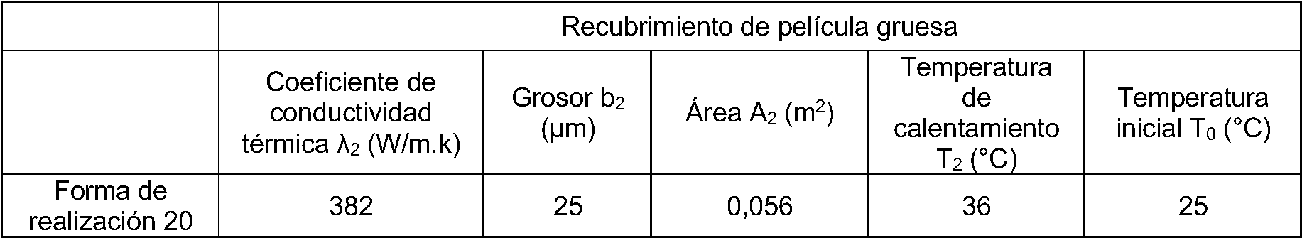
[0029] Las formas de realización siguientes incluyen 20 elementos de película gruesa preparados por el solicitante, y los materiales para preparar la capa de cobertura, donde el recubrimiento de película gruesa y el soporte de los 20 elementos de película gruesa enumerados satisfacen todos las ecuaciones anteriores. El método y la fórmula de preparación detallados se proporcionan como sigue:[0029] The following embodiments include 20 thick film elements prepared by the Applicant, and materials for preparing the topcoat, where the thick film coating and support for the 20 thick film elements listed satisfy all equations previous. The detailed preparation method and formula are provided as follows:
Formas de realización Forms of realization
[0030] Se seleccionó pasta de plata con un coeficiente de conductividad térmica de A2 para preparar el recubrimiento de película gruesa, se seleccionaron poliimidas con un coeficiente de conductividad térmica de A3 para preparar el soporte y se seleccionaron poliimidas con un coeficiente de conductividad térmica de Ai para preparar la capa de cobertura. Las tres capas se unen por sinterización. El área del recubrimiento de película gruesa preparado es A2, el grosor es b2; el área de la capa de cobertura es Ai, el grosor es bi; el área del soporte es A3, el grosor es b3.[0030] Silver paste with a thermal conductivity coefficient of A2 was selected to prepare the thick film coating, polyimides with a thermal conductivity coefficient of A3 were selected to prepare the support, and polyimides with a thermal conductivity coefficient of Ai to prepare the covering layer. The three layers are joined by sintering. The area of the prepared thick film coating is A2, the thickness is b2; the area of the covering layer is Ai, the thickness is bi; the area of the support is A3, the thickness is b3.
[0031] Encender un suministro de energía CC externo para cargar el recubrimiento de película gruesa. La película gruesa comienza a calentarse; cuando se estabiliza el calentamiento, medir la temperatura superficial de la capa de cobertura y el soporte, y se mide la temperatura de calentamiento del recubrimiento de película gruesa bajo un estado de calentamiento estable. Se calcula la tasa de transferencia de calor de la capa de cobertura y el soporte y la tasa de generación de calor del recubrimiento de película gruesa según la fórmula siguiente:[0031] Turn on an external DC power supply to charge the thick film coating. The thick film begins to heat up; When heating is stabilized, measure the surface temperature of the cover layer and the support, and the heating temperature of the thick film coating is measured under a stable heating state. The heat transfer rate of the cover layer and the support and the heat generation rate of the thick film coating are calculated according to the following formula:

[0032] Las tablas 1 a 4 son los 20 elementos de película gruesa preparados por el solicitante. Después de proporcionar electricidad para calentar durante 2 minutos, los elementos de película gruesa se miden según los estándares nacionales para obtener los datos de rendimiento (coeficiente de conductividad térmica, temperatura superficial) tal y como se muestra en las tablas. El grosor, el área de contacto y la temperatura inicial se miden antes del calentamiento.[0032] Tables 1 to 4 are the 20 thick film elements prepared by the applicant. After providing electricity to heat for 2 minutes, thick film elements are measured according to national standards to obtain performance data (coefficient of thermal conductivity, surface temperature) as shown in the tables. Thickness, contact area, and initial temperature are measured before heating.
[0033] La tabla 1 son los datos de rendimiento de las capas de cobertura de los elementos de película gruesa en las formas de realización 1 a 20. Los detalles son como sigue:[0033] Table 1 is the performance data of the covering layers of the thick film elements in Embodiments 1 to 20. The details are as follows:
Tabla 1Table 1


[0034] La tabla 2 son los datos de rendimiento de los recubrimientos de película gruesa de los elementos de película gruesa en las formas de realización 1 a 20. Los detalles son como sigue:[0034] Table 2 is the performance data for thick film coatings of thick film elements in Embodiments 1 to 20. The details are as follows:
Tabla 2Table 2

[0035] La tabla 3 son los datos de rendimiento de los soportes de los elementos de película gruesa en las formas de realización 1 a 20. Los detalles son como sigue:[0035] Table 3 is the performance data of the thick film element supports in Embodiments 1 to 20. The details are as follows:
Tabla 3Table 3

[0036] La tabla 4 es la tasa de transferencia de calor calculada según los datos de rendimiento enumerados en las tablas 1,2 y 3. Las tasas de transferencia de calor de la capa de cobertura, el recubrimiento de película gruesa y el soporte se calculan por relación para obtener las condiciones límite de los materiales de la presente invención, es decir las ecuaciones siguientes: [0036] Table 4 is the heat transfer rate calculated based on the performance data listed in Tables 1,2 and 3. The heat transfer rates of the cover layer, the thick film coating and the support are calculated by relationship to obtain the limit conditions of the materials of the present invention, that is, the following equations:
Q2 > <?3 1 Q2 — Q\ * y Qi=a*Q?, Q2=b*Qi, Q2=cxQj ; donde 0,1 <a<l 50, l<b<2500, 100<c<10000.Q2><? 3 1 Q2 - Q \ * and Qi = a * Q ?, Q2 = b * Qi, Q2 = cxQj; where 0.1 <a <l 50, l <b <2500, 100 <c <10000.
Tabla 4Table 4


Los resultados enumerados en la tabla 4 muestran que todas las películas gruesas preparadas según las formas de realización 1 a 20 satisfacen las ecuaciones; los dos lados de la película gruesa generan calor uniformemente y la diferencia de temperatura entre los dos lados es inferior a 16 °C. El elemento calefactor de película gruesa podría aumentar más de 100 °C después de que se le proporcione electricidad durante 2 minutos, lo que demuestra que el elemento calefactor de película gruesa de la presente invención tiene una alta eficiencia de generación de calor.The results listed in Table 4 show that all the thick films prepared according to Embodiments 1 to 20 satisfy the equations; the two sides of the thick film generate heat uniformly and the temperature difference between the two sides is less than 16 ° C. The thick film heating element could rise more than 100 ° C after electricity is provided for 2 minutes, demonstrating that the thick film heating element of the present invention has high heat generating efficiency.
[0037] Las tablas 5 a 8 son los datos de rendimiento de los elementos de película gruesa de los ejemplos de contraste 1 a 3 de la presente invención. Todos los datos de rendimiento se miden como los mostrados en las tablas 1 a 4. Los detalles son como sigue:[0037] Tables 5 to 8 are the performance data of the thick film elements of contrast examples 1 to 3 of the present invention. All performance data is measured as shown in Tables 1 to 4. Details are as follows:
Tabla 5Table 5

Tabla 6Table 6

Tabla 7Table 7

Tabla 8 Table 8

[0038] El material y la estructura de los elementos de película gruesa de los ejemplos de contraste 1 a 3 enumerados en las tablas anteriores no cumplen el requisito de selección de material de la presente invención ni satisfacen las ecuaciones de la presente invención. Después de proporcionar electricidad y generación de calor, los dos lados de la película gruesa no pudieron generar calor uniformemente y la diferencia de temperatura entre los dos lados es superior a 40 °C. Es el resultado de un aumento de temperatura demasiado rápido de la capa de cobertura y un aumento de temperatura demasiado lento del soporte, lo que no cumple el requisito del elemento de película gruesa con una alta conductividad térmica en sus dos lados de la presente invención o el requisito de producto de la presente invención, lo que demuestra la tasa y correlación de transferencia de calor de la presente invención.[0038] The material and structure of the thick film elements of contrast examples 1 to 3 listed in the tables above do not meet the material selection requirement of the present invention nor do they satisfy the equations of the present invention. After providing electricity and heat generation, the two sides of the thick film were unable to generate heat uniformly and the temperature difference between the two sides is more than 40 ° C. It is the result of too rapid temperature rise of the cover layer and too slow temperature rise of the support, which does not meet the requirement of the thick film element with high thermal conductivity on both sides of the present invention or the product requirement of the present invention, demonstrating the heat transfer rate and correlation of the present invention.
[0039] Según la divulgación y enseñanzas de la especificación mencionada previamente, los expertos en la técnica de la presente invención todavía pueden hacer cambios y modificaciones a la forma de realización mencionada previamente, por lo tanto, el alcance de la presente invención no se limita a las formas de realización descritas específicas y descritas previamente, y todas dichas modificaciones y cambios a la actual invención se encuentran dentro del alcance de la presente invención tal y como se define en las reivindicaciones anexas. [0039] According to the disclosure and teachings of the aforementioned specification, those skilled in the art of the present invention may still make changes and modifications to the previously mentioned embodiment, therefore, the scope of the present invention is not limited to the specific described and previously described embodiments, and all such modifications and changes to the present invention are within the scope of the present invention as defined in the appended claims.
Claims (8)


Applications Claiming Priority (2)
| Application Number | Priority Date | Filing Date | Title |
|---|---|---|---|
| CN201610013179.3A CN106686773B (en) | 2016-01-06 | 2016-01-06 | A kind of thick film heating element of two-sided high thermal conductivity ability |
| PCT/CN2016/077443 WO2017117873A1 (en) | 2016-01-06 | 2016-03-26 | Double-sided thick film heating element having high thermal conductivity |
Publications (1)
| Publication Number | Publication Date |
|---|---|
| ES2766529T3 true ES2766529T3 (en) | 2020-06-12 |
Family
ID=58839121
Family Applications (1)
| Application Number | Title | Priority Date | Filing Date |
|---|---|---|---|
| ES16883017T Active ES2766529T3 (en) | 2016-01-06 | 2016-03-26 | Double-sided thick film heating element with high thermal conductivity |
Country Status (10)
| Country | Link |
|---|---|
| US (1) | US10701763B2 (en) |
| EP (1) | EP3253177B1 (en) |
| JP (1) | JP6301558B2 (en) |
| CN (1) | CN106686773B (en) |
| DK (1) | DK3253177T3 (en) |
| EA (1) | EA037596B1 (en) |
| ES (1) | ES2766529T3 (en) |
| PL (1) | PL3253177T3 (en) |
| PT (1) | PT3253177T (en) |
| WO (1) | WO2017117873A1 (en) |
Families Citing this family (4)
| Publication number | Priority date | Publication date | Assignee | Title |
|---|---|---|---|---|
| CN106686770B (en) * | 2016-02-03 | 2019-09-10 | 黄伟聪 | A kind of coating substrate has the thick film element of high thermal conductivity ability |
| NL2021137B1 (en) * | 2018-06-15 | 2019-12-20 | Boschman Tech Bv | Sintering Process Product Carrier |
| CN113645723A (en) * | 2021-08-09 | 2021-11-12 | 山东启原纳米科技有限公司 | Intelligent flexible electric heating system and preparation method thereof |
| EP4102933B1 (en) | 2021-06-07 | 2023-12-13 | Calefact Limited | Flexible heating device and methods of manufacture and use of same |
Family Cites Families (17)
| Publication number | Priority date | Publication date | Assignee | Title |
|---|---|---|---|---|
| GB9302965D0 (en) * | 1993-02-15 | 1993-03-31 | Strix Ltd | Immersion heaters |
| US5760377A (en) * | 1993-12-14 | 1998-06-02 | Zelenjuk; Jury Iosifovich | Heating element of electrical heater |
| CN2204475Y (en) | 1994-06-17 | 1995-08-02 | 王绍杰 | Super-thin electrothermal basic element |
| JP2663935B2 (en) * | 1996-04-23 | 1997-10-15 | 株式会社デンソー | Plate-shaped ceramic heater and method of manufacturing the same |
| JPH1154248A (en) * | 1997-08-06 | 1999-02-26 | Chuo Riken:Kk | Double-sided plate heater and double heating constant temperature oven |
| DE69834550T2 (en) * | 1997-12-05 | 2007-04-26 | Koninklijke Philips Electronics N.V. | IMMERSION HEATERS |
| JP2000077168A (en) * | 1998-08-31 | 2000-03-14 | Toshiba Lighting & Technology Corp | Heating body, fixing device, and image forming device |
| GB2351894B (en) * | 1999-05-04 | 2003-10-15 | Otter Controls Ltd | Improvements relating to heating elements |
| DE10110792B4 (en) | 2001-03-06 | 2004-09-23 | Schott Glas | Ceramic cooking system with glass ceramic plate, insulation layer and heating elements |
| DE10112234C1 (en) | 2001-03-06 | 2002-07-25 | Schott Glas | Ceramic hob comprises a cooking plate made from glass-ceramic or glass, an electric hot conductor layer, and an insulating layer arranged between the cooking plate and conductor layer |
| CN1697572A (en) * | 2004-05-12 | 2005-11-16 | 环隆电气股份有限公司 | Electronic heating element |
| DE102009010437A1 (en) * | 2009-02-26 | 2010-09-02 | Tesa Se | Heated surface element |
| US20120247641A1 (en) | 2009-10-22 | 2012-10-04 | Datec Coating Corporation | Method of melt bonding high-temperature thermoplastic based heating element to a substrate |
| CN101778501B (en) | 2010-02-05 | 2012-07-11 | 美的集团有限公司 | Thick film heating assembly with dry burning protection function |
| JP2014089798A (en) * | 2011-02-23 | 2014-05-15 | Panasonic Corp | Planar heating element |
| CN102833894B (en) * | 2012-09-03 | 2016-02-17 | 上海泰昌健康科技股份有限公司 | A kind of aluminium alloy heating tube by thick-film heating being applied to Pediluvium apparatus |
| DE102014108356A1 (en) * | 2014-06-13 | 2015-12-17 | Innovative Sensor Technology Ist Ag | Planar heating element with a PTC resistor structure |
-
2016
- 2016-01-06 CN CN201610013179.3A patent/CN106686773B/en active Active
- 2016-03-26 PT PT168830172T patent/PT3253177T/en unknown
- 2016-03-26 ES ES16883017T patent/ES2766529T3/en active Active
- 2016-03-26 US US15/534,489 patent/US10701763B2/en active Active
- 2016-03-26 EP EP16883017.2A patent/EP3253177B1/en active Active
- 2016-03-26 PL PL16883017T patent/PL3253177T3/en unknown
- 2016-03-26 WO PCT/CN2016/077443 patent/WO2017117873A1/en active Application Filing
- 2016-03-26 JP JP2017525109A patent/JP6301558B2/en active Active
- 2016-03-26 EA EA201790670A patent/EA037596B1/en unknown
- 2016-03-26 DK DK16883017.2T patent/DK3253177T3/en active
Also Published As
| Publication number | Publication date |
|---|---|
| US10701763B2 (en) | 2020-06-30 |
| US20180317283A1 (en) | 2018-11-01 |
| JP6301558B2 (en) | 2018-03-28 |
| PT3253177T (en) | 2020-01-15 |
| EP3253177A4 (en) | 2018-07-18 |
| CN106686773A (en) | 2017-05-17 |
| DK3253177T3 (en) | 2020-02-03 |
| EA037596B1 (en) | 2021-04-20 |
| JP2018504736A (en) | 2018-02-15 |
| EA201790670A1 (en) | 2019-04-30 |
| EP3253177A1 (en) | 2017-12-06 |
| PL3253177T3 (en) | 2020-04-30 |
| EP3253177B1 (en) | 2019-10-30 |
| CN106686773B (en) | 2019-09-10 |
| WO2017117873A1 (en) | 2017-07-13 |
Similar Documents
| Publication | Publication Date | Title |
|---|---|---|
| ES2766529T3 (en) | Double-sided thick film heating element with high thermal conductivity | |
| RU2020124810A (en) | AEROSOL GENERATING DEVICE WITH A HEATER | |
| RU2121244C1 (en) | Equipment distributing heat | |
| JP2014020371A5 (en) | ||
| WO2016132125A1 (en) | Heaters | |
| CN111465131A (en) | Temperature measurement feedback electromagnetic induction heating body based on thick film technology | |
| CN114158785A (en) | Heating element and aerosol-generating device | |
| ES2757326T3 (en) | Thick film element provided with a coating layer that has a high heat conduction capacity | |
| ES2767804T3 (en) | Thick film element coated with a substrate and having a high thermal conduction capacity | |
| CA2959248A1 (en) | Specific heater circuit track pattern coated on a thin heater plate for high temperature uniformity | |
| JP6307286B2 (en) | heater | |
| JP7472419B2 (en) | Hair iron with ceramic heater | |
| JP6874079B2 (en) | Heated smoking equipment | |
| CN208567098U (en) | Face electric heater | |
| US11828490B2 (en) | Ceramic heater for heating water in an appliance | |
| CN207721216U (en) | Electronic cigarette and its heating device | |
| CN217218203U (en) | Heating element and aerosol-generating device | |
| CN110381613A (en) | A kind of nanometer of planar resistive film metal electric heating device | |
| KR100735104B1 (en) | Structure of heater for hair iron having onebody type of heating unit and plate | |
| KR20060081486A (en) | Plane heater | |
| CN217771483U (en) | Heating element and aerosol generating device | |
| TWM522534U (en) | Electric heating tube and electric heater | |
| RU75526U1 (en) | ELECTRIC HEATER | |
| JP2010165467A5 (en) | ||
| KR20230091005A (en) | Surface heating heater pipe and aerosol generating device including the same |