ES2746526T3 - Catalytic cracking procedure for the treatment of a low carbon content Conradson - Google Patents
Catalytic cracking procedure for the treatment of a low carbon content Conradson Download PDFInfo
- Publication number
- ES2746526T3 ES2746526T3 ES11811059T ES11811059T ES2746526T3 ES 2746526 T3 ES2746526 T3 ES 2746526T3 ES 11811059 T ES11811059 T ES 11811059T ES 11811059 T ES11811059 T ES 11811059T ES 2746526 T3 ES2746526 T3 ES 2746526T3
- Authority
- ES
- Spain
- Prior art keywords
- coke
- catalyst
- separation
- recycling
- weight
- Prior art date
- Legal status (The legal status is an assumption and is not a legal conclusion. Google has not performed a legal analysis and makes no representation as to the accuracy of the status listed.)
- Active
Links
Classifications
-
- C—CHEMISTRY; METALLURGY
- C10—PETROLEUM, GAS OR COKE INDUSTRIES; TECHNICAL GASES CONTAINING CARBON MONOXIDE; FUELS; LUBRICANTS; PEAT
- C10G—CRACKING HYDROCARBON OILS; PRODUCTION OF LIQUID HYDROCARBON MIXTURES, e.g. BY DESTRUCTIVE HYDROGENATION, OLIGOMERISATION, POLYMERISATION; RECOVERY OF HYDROCARBON OILS FROM OIL-SHALE, OIL-SAND, OR GASES; REFINING MIXTURES MAINLY CONSISTING OF HYDROCARBONS; REFORMING OF NAPHTHA; MINERAL WAXES
- C10G11/00—Catalytic cracking, in the absence of hydrogen, of hydrocarbon oils
- C10G11/20—Catalytic cracking, in the absence of hydrogen, of hydrocarbon oils by direct contact with inert heated gases or vapours
-
- C—CHEMISTRY; METALLURGY
- C10—PETROLEUM, GAS OR COKE INDUSTRIES; TECHNICAL GASES CONTAINING CARBON MONOXIDE; FUELS; LUBRICANTS; PEAT
- C10G—CRACKING HYDROCARBON OILS; PRODUCTION OF LIQUID HYDROCARBON MIXTURES, e.g. BY DESTRUCTIVE HYDROGENATION, OLIGOMERISATION, POLYMERISATION; RECOVERY OF HYDROCARBON OILS FROM OIL-SHALE, OIL-SAND, OR GASES; REFINING MIXTURES MAINLY CONSISTING OF HYDROCARBONS; REFORMING OF NAPHTHA; MINERAL WAXES
- C10G11/00—Catalytic cracking, in the absence of hydrogen, of hydrocarbon oils
- C10G11/14—Catalytic cracking, in the absence of hydrogen, of hydrocarbon oils with preheated moving solid catalysts
- C10G11/18—Catalytic cracking, in the absence of hydrogen, of hydrocarbon oils with preheated moving solid catalysts according to the "fluidised-bed" technique
-
- B—PERFORMING OPERATIONS; TRANSPORTING
- B01—PHYSICAL OR CHEMICAL PROCESSES OR APPARATUS IN GENERAL
- B01J—CHEMICAL OR PHYSICAL PROCESSES, e.g. CATALYSIS OR COLLOID CHEMISTRY; THEIR RELEVANT APPARATUS
- B01J19/00—Chemical, physical or physico-chemical processes in general; Their relevant apparatus
- B01J19/32—Packing elements in the form of grids or built-up elements for forming a unit or module inside the apparatus for mass or heat transfer
-
- B—PERFORMING OPERATIONS; TRANSPORTING
- B01—PHYSICAL OR CHEMICAL PROCESSES OR APPARATUS IN GENERAL
- B01J—CHEMICAL OR PHYSICAL PROCESSES, e.g. CATALYSIS OR COLLOID CHEMISTRY; THEIR RELEVANT APPARATUS
- B01J8/00—Chemical or physical processes in general, conducted in the presence of fluids and solid particles; Apparatus for such processes
- B01J8/0015—Feeding of the particles in the reactor; Evacuation of the particles out of the reactor
- B01J8/0045—Feeding of the particles in the reactor; Evacuation of the particles out of the reactor by means of a rotary device in the flow channel
-
- B—PERFORMING OPERATIONS; TRANSPORTING
- B01—PHYSICAL OR CHEMICAL PROCESSES OR APPARATUS IN GENERAL
- B01J—CHEMICAL OR PHYSICAL PROCESSES, e.g. CATALYSIS OR COLLOID CHEMISTRY; THEIR RELEVANT APPARATUS
- B01J8/00—Chemical or physical processes in general, conducted in the presence of fluids and solid particles; Apparatus for such processes
- B01J8/18—Chemical or physical processes in general, conducted in the presence of fluids and solid particles; Apparatus for such processes with fluidised particles
- B01J8/1818—Feeding of the fluidising gas
- B01J8/1827—Feeding of the fluidising gas the fluidising gas being a reactant
-
- B—PERFORMING OPERATIONS; TRANSPORTING
- B01—PHYSICAL OR CHEMICAL PROCESSES OR APPARATUS IN GENERAL
- B01J—CHEMICAL OR PHYSICAL PROCESSES, e.g. CATALYSIS OR COLLOID CHEMISTRY; THEIR RELEVANT APPARATUS
- B01J8/00—Chemical or physical processes in general, conducted in the presence of fluids and solid particles; Apparatus for such processes
- B01J8/18—Chemical or physical processes in general, conducted in the presence of fluids and solid particles; Apparatus for such processes with fluidised particles
- B01J8/24—Chemical or physical processes in general, conducted in the presence of fluids and solid particles; Apparatus for such processes with fluidised particles according to "fluidised-bed" technique
- B01J8/26—Chemical or physical processes in general, conducted in the presence of fluids and solid particles; Apparatus for such processes with fluidised particles according to "fluidised-bed" technique with two or more fluidised beds, e.g. reactor and regeneration installations
- B01J8/28—Chemical or physical processes in general, conducted in the presence of fluids and solid particles; Apparatus for such processes with fluidised particles according to "fluidised-bed" technique with two or more fluidised beds, e.g. reactor and regeneration installations the one above the other
- B01J8/30—Chemical or physical processes in general, conducted in the presence of fluids and solid particles; Apparatus for such processes with fluidised particles according to "fluidised-bed" technique with two or more fluidised beds, e.g. reactor and regeneration installations the one above the other the edge of a lower bed projecting beyond the edge of the superjacent bed
-
- B—PERFORMING OPERATIONS; TRANSPORTING
- B01—PHYSICAL OR CHEMICAL PROCESSES OR APPARATUS IN GENERAL
- B01J—CHEMICAL OR PHYSICAL PROCESSES, e.g. CATALYSIS OR COLLOID CHEMISTRY; THEIR RELEVANT APPARATUS
- B01J8/00—Chemical or physical processes in general, conducted in the presence of fluids and solid particles; Apparatus for such processes
- B01J8/18—Chemical or physical processes in general, conducted in the presence of fluids and solid particles; Apparatus for such processes with fluidised particles
- B01J8/24—Chemical or physical processes in general, conducted in the presence of fluids and solid particles; Apparatus for such processes with fluidised particles according to "fluidised-bed" technique
- B01J8/34—Chemical or physical processes in general, conducted in the presence of fluids and solid particles; Apparatus for such processes with fluidised particles according to "fluidised-bed" technique with stationary packing material in the fluidised bed, e.g. bricks, wire rings, baffles
-
- C—CHEMISTRY; METALLURGY
- C10—PETROLEUM, GAS OR COKE INDUSTRIES; TECHNICAL GASES CONTAINING CARBON MONOXIDE; FUELS; LUBRICANTS; PEAT
- C10G—CRACKING HYDROCARBON OILS; PRODUCTION OF LIQUID HYDROCARBON MIXTURES, e.g. BY DESTRUCTIVE HYDROGENATION, OLIGOMERISATION, POLYMERISATION; RECOVERY OF HYDROCARBON OILS FROM OIL-SHALE, OIL-SAND, OR GASES; REFINING MIXTURES MAINLY CONSISTING OF HYDROCARBONS; REFORMING OF NAPHTHA; MINERAL WAXES
- C10G11/00—Catalytic cracking, in the absence of hydrogen, of hydrocarbon oils
- C10G11/14—Catalytic cracking, in the absence of hydrogen, of hydrocarbon oils with preheated moving solid catalysts
- C10G11/18—Catalytic cracking, in the absence of hydrogen, of hydrocarbon oils with preheated moving solid catalysts according to the "fluidised-bed" technique
- C10G11/182—Regeneration
-
- C—CHEMISTRY; METALLURGY
- C10—PETROLEUM, GAS OR COKE INDUSTRIES; TECHNICAL GASES CONTAINING CARBON MONOXIDE; FUELS; LUBRICANTS; PEAT
- C10G—CRACKING HYDROCARBON OILS; PRODUCTION OF LIQUID HYDROCARBON MIXTURES, e.g. BY DESTRUCTIVE HYDROGENATION, OLIGOMERISATION, POLYMERISATION; RECOVERY OF HYDROCARBON OILS FROM OIL-SHALE, OIL-SAND, OR GASES; REFINING MIXTURES MAINLY CONSISTING OF HYDROCARBONS; REFORMING OF NAPHTHA; MINERAL WAXES
- C10G11/00—Catalytic cracking, in the absence of hydrogen, of hydrocarbon oils
- C10G11/14—Catalytic cracking, in the absence of hydrogen, of hydrocarbon oils with preheated moving solid catalysts
- C10G11/18—Catalytic cracking, in the absence of hydrogen, of hydrocarbon oils with preheated moving solid catalysts according to the "fluidised-bed" technique
- C10G11/187—Controlling or regulating
-
- B—PERFORMING OPERATIONS; TRANSPORTING
- B01—PHYSICAL OR CHEMICAL PROCESSES OR APPARATUS IN GENERAL
- B01J—CHEMICAL OR PHYSICAL PROCESSES, e.g. CATALYSIS OR COLLOID CHEMISTRY; THEIR RELEVANT APPARATUS
- B01J2208/00—Processes carried out in the presence of solid particles; Reactors therefor
- B01J2208/00008—Controlling the process
- B01J2208/00017—Controlling the temperature
-
- B—PERFORMING OPERATIONS; TRANSPORTING
- B01—PHYSICAL OR CHEMICAL PROCESSES OR APPARATUS IN GENERAL
- B01J—CHEMICAL OR PHYSICAL PROCESSES, e.g. CATALYSIS OR COLLOID CHEMISTRY; THEIR RELEVANT APPARATUS
- B01J2208/00—Processes carried out in the presence of solid particles; Reactors therefor
- B01J2208/00008—Controlling the process
- B01J2208/00548—Flow
- B01J2208/00557—Flow controlling the residence time inside the reactor vessel
-
- B—PERFORMING OPERATIONS; TRANSPORTING
- B01—PHYSICAL OR CHEMICAL PROCESSES OR APPARATUS IN GENERAL
- B01J—CHEMICAL OR PHYSICAL PROCESSES, e.g. CATALYSIS OR COLLOID CHEMISTRY; THEIR RELEVANT APPARATUS
- B01J2208/00—Processes carried out in the presence of solid particles; Reactors therefor
- B01J2208/00796—Details of the reactor or of the particulate material
- B01J2208/00991—Disengagement zone in fluidised-bed reactors
-
- C—CHEMISTRY; METALLURGY
- C10—PETROLEUM, GAS OR COKE INDUSTRIES; TECHNICAL GASES CONTAINING CARBON MONOXIDE; FUELS; LUBRICANTS; PEAT
- C10G—CRACKING HYDROCARBON OILS; PRODUCTION OF LIQUID HYDROCARBON MIXTURES, e.g. BY DESTRUCTIVE HYDROGENATION, OLIGOMERISATION, POLYMERISATION; RECOVERY OF HYDROCARBON OILS FROM OIL-SHALE, OIL-SAND, OR GASES; REFINING MIXTURES MAINLY CONSISTING OF HYDROCARBONS; REFORMING OF NAPHTHA; MINERAL WAXES
- C10G2300/00—Aspects relating to hydrocarbon processing covered by groups C10G1/00 - C10G99/00
- C10G2300/10—Feedstock materials
- C10G2300/1011—Biomass
- C10G2300/1014—Biomass of vegetal origin
-
- C—CHEMISTRY; METALLURGY
- C10—PETROLEUM, GAS OR COKE INDUSTRIES; TECHNICAL GASES CONTAINING CARBON MONOXIDE; FUELS; LUBRICANTS; PEAT
- C10G—CRACKING HYDROCARBON OILS; PRODUCTION OF LIQUID HYDROCARBON MIXTURES, e.g. BY DESTRUCTIVE HYDROGENATION, OLIGOMERISATION, POLYMERISATION; RECOVERY OF HYDROCARBON OILS FROM OIL-SHALE, OIL-SAND, OR GASES; REFINING MIXTURES MAINLY CONSISTING OF HYDROCARBONS; REFORMING OF NAPHTHA; MINERAL WAXES
- C10G2300/00—Aspects relating to hydrocarbon processing covered by groups C10G1/00 - C10G99/00
- C10G2300/10—Feedstock materials
- C10G2300/1022—Fischer-Tropsch products
-
- C—CHEMISTRY; METALLURGY
- C10—PETROLEUM, GAS OR COKE INDUSTRIES; TECHNICAL GASES CONTAINING CARBON MONOXIDE; FUELS; LUBRICANTS; PEAT
- C10G—CRACKING HYDROCARBON OILS; PRODUCTION OF LIQUID HYDROCARBON MIXTURES, e.g. BY DESTRUCTIVE HYDROGENATION, OLIGOMERISATION, POLYMERISATION; RECOVERY OF HYDROCARBON OILS FROM OIL-SHALE, OIL-SAND, OR GASES; REFINING MIXTURES MAINLY CONSISTING OF HYDROCARBONS; REFORMING OF NAPHTHA; MINERAL WAXES
- C10G2300/00—Aspects relating to hydrocarbon processing covered by groups C10G1/00 - C10G99/00
- C10G2300/10—Feedstock materials
- C10G2300/1077—Vacuum residues
-
- C—CHEMISTRY; METALLURGY
- C10—PETROLEUM, GAS OR COKE INDUSTRIES; TECHNICAL GASES CONTAINING CARBON MONOXIDE; FUELS; LUBRICANTS; PEAT
- C10G—CRACKING HYDROCARBON OILS; PRODUCTION OF LIQUID HYDROCARBON MIXTURES, e.g. BY DESTRUCTIVE HYDROGENATION, OLIGOMERISATION, POLYMERISATION; RECOVERY OF HYDROCARBON OILS FROM OIL-SHALE, OIL-SAND, OR GASES; REFINING MIXTURES MAINLY CONSISTING OF HYDROCARBONS; REFORMING OF NAPHTHA; MINERAL WAXES
- C10G2300/00—Aspects relating to hydrocarbon processing covered by groups C10G1/00 - C10G99/00
- C10G2300/10—Feedstock materials
- C10G2300/1096—Aromatics or polyaromatics
-
- C—CHEMISTRY; METALLURGY
- C10—PETROLEUM, GAS OR COKE INDUSTRIES; TECHNICAL GASES CONTAINING CARBON MONOXIDE; FUELS; LUBRICANTS; PEAT
- C10G—CRACKING HYDROCARBON OILS; PRODUCTION OF LIQUID HYDROCARBON MIXTURES, e.g. BY DESTRUCTIVE HYDROGENATION, OLIGOMERISATION, POLYMERISATION; RECOVERY OF HYDROCARBON OILS FROM OIL-SHALE, OIL-SAND, OR GASES; REFINING MIXTURES MAINLY CONSISTING OF HYDROCARBONS; REFORMING OF NAPHTHA; MINERAL WAXES
- C10G2300/00—Aspects relating to hydrocarbon processing covered by groups C10G1/00 - C10G99/00
- C10G2300/20—Characteristics of the feedstock or the products
- C10G2300/201—Impurities
- C10G2300/205—Metal content
- C10G2300/206—Asphaltenes
-
- C—CHEMISTRY; METALLURGY
- C10—PETROLEUM, GAS OR COKE INDUSTRIES; TECHNICAL GASES CONTAINING CARBON MONOXIDE; FUELS; LUBRICANTS; PEAT
- C10G—CRACKING HYDROCARBON OILS; PRODUCTION OF LIQUID HYDROCARBON MIXTURES, e.g. BY DESTRUCTIVE HYDROGENATION, OLIGOMERISATION, POLYMERISATION; RECOVERY OF HYDROCARBON OILS FROM OIL-SHALE, OIL-SAND, OR GASES; REFINING MIXTURES MAINLY CONSISTING OF HYDROCARBONS; REFORMING OF NAPHTHA; MINERAL WAXES
- C10G2300/00—Aspects relating to hydrocarbon processing covered by groups C10G1/00 - C10G99/00
- C10G2300/20—Characteristics of the feedstock or the products
- C10G2300/30—Physical properties of feedstocks or products
- C10G2300/301—Boiling range
-
- C—CHEMISTRY; METALLURGY
- C10—PETROLEUM, GAS OR COKE INDUSTRIES; TECHNICAL GASES CONTAINING CARBON MONOXIDE; FUELS; LUBRICANTS; PEAT
- C10G—CRACKING HYDROCARBON OILS; PRODUCTION OF LIQUID HYDROCARBON MIXTURES, e.g. BY DESTRUCTIVE HYDROGENATION, OLIGOMERISATION, POLYMERISATION; RECOVERY OF HYDROCARBON OILS FROM OIL-SHALE, OIL-SAND, OR GASES; REFINING MIXTURES MAINLY CONSISTING OF HYDROCARBONS; REFORMING OF NAPHTHA; MINERAL WAXES
- C10G2300/00—Aspects relating to hydrocarbon processing covered by groups C10G1/00 - C10G99/00
- C10G2300/40—Characteristics of the process deviating from typical ways of processing
- C10G2300/4081—Recycling aspects
-
- C—CHEMISTRY; METALLURGY
- C10—PETROLEUM, GAS OR COKE INDUSTRIES; TECHNICAL GASES CONTAINING CARBON MONOXIDE; FUELS; LUBRICANTS; PEAT
- C10G—CRACKING HYDROCARBON OILS; PRODUCTION OF LIQUID HYDROCARBON MIXTURES, e.g. BY DESTRUCTIVE HYDROGENATION, OLIGOMERISATION, POLYMERISATION; RECOVERY OF HYDROCARBON OILS FROM OIL-SHALE, OIL-SAND, OR GASES; REFINING MIXTURES MAINLY CONSISTING OF HYDROCARBONS; REFORMING OF NAPHTHA; MINERAL WAXES
- C10G2300/00—Aspects relating to hydrocarbon processing covered by groups C10G1/00 - C10G99/00
- C10G2300/40—Characteristics of the process deviating from typical ways of processing
- C10G2300/4093—Catalyst stripping
-
- C—CHEMISTRY; METALLURGY
- C10—PETROLEUM, GAS OR COKE INDUSTRIES; TECHNICAL GASES CONTAINING CARBON MONOXIDE; FUELS; LUBRICANTS; PEAT
- C10G—CRACKING HYDROCARBON OILS; PRODUCTION OF LIQUID HYDROCARBON MIXTURES, e.g. BY DESTRUCTIVE HYDROGENATION, OLIGOMERISATION, POLYMERISATION; RECOVERY OF HYDROCARBON OILS FROM OIL-SHALE, OIL-SAND, OR GASES; REFINING MIXTURES MAINLY CONSISTING OF HYDROCARBONS; REFORMING OF NAPHTHA; MINERAL WAXES
- C10G2300/00—Aspects relating to hydrocarbon processing covered by groups C10G1/00 - C10G99/00
- C10G2300/70—Catalyst aspects
- C10G2300/708—Coking aspect, coke content and composition of deposits
-
- Y—GENERAL TAGGING OF NEW TECHNOLOGICAL DEVELOPMENTS; GENERAL TAGGING OF CROSS-SECTIONAL TECHNOLOGIES SPANNING OVER SEVERAL SECTIONS OF THE IPC; TECHNICAL SUBJECTS COVERED BY FORMER USPC CROSS-REFERENCE ART COLLECTIONS [XRACs] AND DIGESTS
- Y02—TECHNOLOGIES OR APPLICATIONS FOR MITIGATION OR ADAPTATION AGAINST CLIMATE CHANGE
- Y02P—CLIMATE CHANGE MITIGATION TECHNOLOGIES IN THE PRODUCTION OR PROCESSING OF GOODS
- Y02P30/00—Technologies relating to oil refining and petrochemical industry
- Y02P30/20—Technologies relating to oil refining and petrochemical industry using bio-feedstock
-
- Y—GENERAL TAGGING OF NEW TECHNOLOGICAL DEVELOPMENTS; GENERAL TAGGING OF CROSS-SECTIONAL TECHNOLOGIES SPANNING OVER SEVERAL SECTIONS OF THE IPC; TECHNICAL SUBJECTS COVERED BY FORMER USPC CROSS-REFERENCE ART COLLECTIONS [XRACs] AND DIGESTS
- Y02—TECHNOLOGIES OR APPLICATIONS FOR MITIGATION OR ADAPTATION AGAINST CLIMATE CHANGE
- Y02P—CLIMATE CHANGE MITIGATION TECHNOLOGIES IN THE PRODUCTION OR PROCESSING OF GOODS
- Y02P30/00—Technologies relating to oil refining and petrochemical industry
- Y02P30/40—Ethylene production
Landscapes
- Chemical & Material Sciences (AREA)
- Organic Chemistry (AREA)
- Chemical Kinetics & Catalysis (AREA)
- Engineering & Computer Science (AREA)
- Oil, Petroleum & Natural Gas (AREA)
- Combustion & Propulsion (AREA)
- General Chemical & Material Sciences (AREA)
- Physics & Mathematics (AREA)
- Thermal Sciences (AREA)
- Production Of Liquid Hydrocarbon Mixture For Refining Petroleum (AREA)
Abstract
Procedimiento de craqueo catalítico en lecho fluidizado de una baja carga de coquización de carbono Conradson menor o igual al 0,1 % en peso y un contenido de hidrógeno mayor o igual al 12,7 % en peso que comprende al menos una etapa de craqueo de la carga en presencia de un catalizador, una etapa de separación de los efluentes de los granos de catalizador coquizados y una etapa de regeneración de dichos granos por combustión parcial o total del coque, y el reciclado en catalizador distribuido de manera homogénea y poco coquizado, antes de la regeneración, de al menos un efluente carbonado y/o hidrocarbonado denominado coquizado, caracterizado porque la cantidad de efluente de coque inyectada en el catalizador coquizado se ajusta para proporcionar una cantidad de coque Qr adicional en el catalizador y satisfacer la siguiente ecuación (I):**Fórmula** donde Qi es el contenido de coque inicial en el catalizador coquizado después del craqueo de la carga y Qt o delta coque es el contenido de coque quemado por combustión total o parcial necesario para mantener el balance térmico del procedimiento y mantener el catalizador regenerado a una temperatura mayor o igual a 690 °C, que preferiblemente varía de 690 °C a 750 °C, comprendiendo dicho efluente de coque un contenido de compuestos aromáticos superior al 50 % en peso y comprendiendo el 20 % en peso o más de compuestos poliaromáticos.Fluidized bed catalytic cracking process with a low Conradson carbon coking load of less than or equal to 0.1% by weight and a hydrogen content of greater than or equal to 12.7% by weight, comprising at least one stage of cracking of charging in the presence of a catalyst, a step for separating the effluents from the coked catalyst grains and a step for regenerating said grains by partial or total combustion of the coke, and recycling into a catalyst distributed in a homogeneous and slightly coked manner, prior to regeneration, of at least one carbon and / or hydrocarbon effluent called coked, characterized in that the amount of coke effluent injected into the coked catalyst is adjusted to provide an additional amount of Qr coke in the catalyst and satisfy the following equation ( I): ** Formula ** where Qi is the initial coke content in the coked catalyst after charge cracking and Qt or delta coke is the d content e coke burned by total or partial combustion necessary to maintain the thermal balance of the process and maintain the regenerated catalyst at a temperature greater than or equal to 690 ° C, which preferably varies from 690 ° C to 750 ° C, said coke effluent comprising a aromatic compound content greater than 50% by weight and comprising 20% by weight or more of polyaromatic compounds.
Description
DESCRIPCIÓNDESCRIPTION
Procedimiento de craqueo catalítico para el tratamiento de una fracción con bajo contenido de carbono Conradson Campo de la invención Catalytic cracking procedure for the treatment of a low carbon content Conradson Field of the invention
La presente invención se sitúa en el campo del craqueo catalítico de fracciones de petróleo, especialmente fracciones que tienen un bajo nivel de carbono Conradson y un alto contenido de hidrógeno y que, por lo tanto, dificultan la obtención del balance térmico de la unidad.The present invention is in the field of catalytic cracking of petroleum fractions, especially fractions that have a low Conradson carbon level and a high hydrogen content and, therefore, make it difficult to obtain the thermal balance of the unit.
En una unidad de craqueo catalítico (denominado FCC), el balance térmico está asegurado por la combustión del coque depositado sobre el catalizador durante la etapa de reacción. Esta combustión tiene lugar en la zona de regeneración. Típicamente, el catalizador ingresa en la zona de regeneración con un contenido de coque (definido como la masa de coque sobre la masa de catalizador en porcentaje en peso) comprendido entre el 0,5 y el 1 % en peso y sale de dicha zona con un contenido de coque comprendido entre el 0,1 y el 0,5 % en peso para regeneradores que funcionan en combustión parcial o comprendido entre el 0,1 y el 0,05 % en peso o incluso menos del 0,01 % en peso para regeneradores que operan en combustión total.In a catalytic cracking unit (called FCC), the thermal balance is ensured by the combustion of the coke deposited on the catalyst during the reaction stage. This combustion takes place in the regeneration zone. Typically, the catalyst enters the regeneration zone with a coke content (defined as the mass of coke over the mass of catalyst in percent by weight) between 0.5 and 1% by weight and leaves the zone with a coke content of between 0.1 and 0.5% by weight for regenerators operating in partial combustion or between 0.1 and 0.05% by weight or even less than 0.01% by weight for regenerators operating in total combustion.
En una regeneración de combustión completa, todo el coque se quema (contenido típico de CO o monóxido de carbono en humos cercanos a cero) mientras que, en la combustión parcial, la combustión del coque produce CO en un pequeño volumen porcentual, típicamente del 0,5 al 10 % en volumen, dependiendo del flujo de aire y el grado de finalización de la combustión para combustiones incompletas.In a full combustion regeneration, all coke is burned (typical CO or carbon monoxide content in fumes close to zero) while, in partial combustion, coke combustion produces CO in a small percentage volume, typically 0 , 5 to 10% by volume, depending on the air flow and the degree of completion of combustion for incomplete combustions.
El contenido de carbono Conradson (o CCR) de la carga está definido por la norma ASTM D 482 y representa para la persona experta una evaluación de la cantidad de coque que la carga puede producir durante la reacción de craqueo catalítico que tiene lugar en el reactor principal de la unidad. Dependiendo del contenido de carbono Conradson de la carga, es posible dimensionar la unidad para un rendimiento de coque correspondiente al craqueo de la carga con el fin de satisfacer el balance térmico de la unidad que controlará su correcto funcionamiento.The Conradson carbon content (or CCR) of the charge is defined by ASTM D 482 and represents to the skilled person an assessment of the amount of coke the charge can produce during the catalytic cracking reaction taking place in the reactor main unit. Depending on the Conradson carbon content of the charge, it is possible to size the unit for a coke performance corresponding to the cracking of the charge in order to satisfy the thermal balance of the unit that will control its proper operation.
Las fracciones pesadas convencionales procesadas en una unidad de FCC generalmente tienen carbono Conradson comprendido en el rango del 0,2 al 10 % en peso.Conventional heavy fractions processed in an FCC unit generally have Conradson carbon in the range of 0.2 to 10 wt%.
Las fracciones tratadas en una unidad de FCC de acuerdo con la presente invención pueden tener un carbono Conradson menor o igual al 0,1 % en peso y un contenido de hidrógeno mayor o igual al 12,7 % en peso.Fractions treated in an FCC unit according to the present invention may have a Conradson carbon less than or equal to 0.1% by weight and a hydrogen content greater than or equal to 12.7% by weight.
Examen de la técnica anteriorExamination of the prior art
Es conocido por los expertos en la materia equilibrar los balances térmicos para impulsar la combustión hacia el regenerador inyectando más aire para una cantidad de coque dada, es decir, disminuyendo el porcentaje en volumen de monóxido de carbono (o CO) en los humos, lo que ayuda a aumentar la temperatura del catalizador en dicho regenerador y debe ayudar a garantizar el balance térmico de la unidad. Sin embargo, no es necesario aumentar la cantidad de aire inyectado más allá de la cantidad requerida para quemar el coque presente en el catalizador coquizado del lecho denso en el regenerador. La combustión del coque permite aumentar la temperatura del catalizador así regenerado hasta la temperatura deseada de craqueo de la materia prima y así equilibrar el balance térmico de la unidad.It is known to those skilled in the art to balance the thermal balances to drive combustion towards the regenerator by injecting more air for a given amount of coke, that is, decreasing the volume percentage of carbon monoxide (or CO) in the fumes, which which helps increase the temperature of the catalyst in said regenerator and should help ensure the thermal balance of the unit. However, it is not necessary to increase the amount of air injected beyond the amount required to burn the coke present in the coke catalyst from the dense bed in the regenerator. The combustion of the coke allows the temperature of the regenerated catalyst to be raised to the desired cracking temperature of the raw material and thus to balance the thermal balance of the unit.
Cuando el aumento en el volumen de aire inyectado no es suficiente o posible, se sabe por la técnica anterior reciclar en el regenerador una fracción de FCC con alto potencial de coque, llamada fracción de coque, estando introducida dicha fracción directamente en el regenerador. Esta fracción de coque es generalmente una fracción resultante del craqueo de la carga, que generalmente es la fracción de “lodo”, es decir, una fracción predominantemente aromática de 360 °C+, o cualquier fracción hidrocarbonada como fueloil N° 2 o combustible para uso doméstico. Este reciclaje de una fracción de coque en el regenerador, que se ejecuta en las fases de arranque de la unidad, es difícil y es una fuente de problemas durante un uso continuo. De hecho, dado que las temperaturas en el regenerador son del orden de 650 °C a 750 °C, una parte del reciclado se vaporiza formando gases craqueados que terminarán en la fase diluida del regenerador donde bien pueden crearse puntos calientes que dañan el regenerador. Este fenómeno a menudo llamado “afterburning” o poscombustión puede definirse como una recuperación de la combustión en un punto no deseado del regenerador, por ejemplo, en la fase diluida donde el catalizador sólido está presente en una cantidad menor, o en la entrada o en el interior de uno de los ciclones también presente en el recinto del regenerador, o incluso en los tubos de evacuación de los gases de combustión. En el resto del texto se conservará el término “poscombustión” bien aceptado y practicado por el experto en la técnica.When the increase in the volume of air injected is not sufficient or possible, it is known by the prior art to recycle in the regenerator a fraction of FCC with high coke potential, called the coke fraction, said fraction being introduced directly into the regenerator. This coke fraction is generally a fraction resulting from the cracking of the charge, which is generally the "sludge" fraction, that is, a predominantly aromatic 360 ° C + fraction, or any hydrocarbon fraction such as No. 2 fuel oil or fuel for use domestic. This recycling of a fraction of coke in the regenerator, which runs in the startup stages of the unit, is difficult and is a source of problems during continued use. In fact, since the temperatures in the regenerator are in the order of 650 ° C to 750 ° C, a part of the recycle vaporizes forming cracked gases that will end up in the dilute phase of the regenerator where hot spots can be created that damage the regenerator. This phenomenon often called "afterburning" or post-combustion can be defined as a recovery of combustion at an undesired point in the regenerator, for example, in the dilute phase where the solid catalyst is present in a smaller amount, or at the inlet or in the interior of one of the cyclones also present in the regenerator enclosure, or even in the flue gas evacuation tubes. In the rest of the text the term "post-combustion" will be kept, well accepted and practiced by the person skilled in the art.
Además, esta corriente de reciclaje puede arder en el lecho del catalizador localmente formando un frente de llama a alta temperatura. Este frente de llama genera puntos calientes con temperaturas localmente altas dentro del lecho del catalizador. Dado que el vapor de agua también se forma en el momento de la combustión de estos hidrocarburos, estas altas temperaturas locales combinadas con la presencia de vapor de agua debilitan la parte activa del catalizador (zeolita) y, por lo tanto, desactivan su función de craqueo. Esto se llama desactivación hidrotérmica del catalizador. Cabe señalar que, cuanto más rica sea esta fracción reciclada en hidrógeno (cuanto más ligera sea la fracción, mayor será su contenido de hidrógeno, generando más vapor de agua por combustión), mayor será la generación de vapor de agua resultante de su combustión.Furthermore, this recycle stream can burn locally in the catalyst bed forming a high temperature flame front. This flame front generates hot spots with locally high temperatures within the catalyst bed. Since water vapor is also formed at the time of combustion of these hydrocarbons, these high local temperatures combined with the presence of water vapor weaken the active part of the catalyst (zeolite) and, therefore, deactivate its function of cracking. This is called hydrothermal catalyst deactivation. It should be noted that the richer this recycled hydrogen fraction (how much the lighter the fraction, the higher its hydrogen content, generating more water vapor by combustion), the greater the generation of water vapor resulting from its combustion.
También se sabe que reciclar hidrocarburos de tipo alquitrán o coque al separador para optimizar la producción de gasolina y olefinas mediante el uso de catalizadores bifuncionales con reciclado de hidrocarburos (documento US 3856659) o para usar la exotermicidad del reciclado para mejorar la separación de los granos de catalizador coquizados en el separador (documento US 4888103). En ninguno de estos documentos, se menciona la optimización de la reacción de coquización en el catalizador inicialmente coquizado por la carga, con miras a tratar las bajas cargas de coquización que no permiten obtener el balance térmico necesario para el buen funcionamiento del procedimiento de craqueo catalítico.It is also known to recycle tar or coke hydrocarbons to the separator to optimize the production of gasoline and olefins through the use of bifunctional hydrocarbon recycle catalysts (US 3856659) or to use the exothermicity of recycling to improve grain separation. of catalyst coked in the separator (US 4888103). In none of these documents is the optimization of the coking reaction mentioned in the catalyst initially coked by the charge, with a view to treating the low coking charges that do not allow obtaining the thermal balance necessary for the proper operation of the catalytic cracking process .
En el documento EP 2072605, el regenerador se usa como un generador de gas de síntesis: para este propósito, una cantidad de coque de coque se recicla al catalizador coquizado mediante la carga al separador. Sin embargo, esta cantidad es mucho mayor que la requerida para el funcionamiento normal de un regenerador en combustión, lo que permite mantener la temperatura del catalizador regenerado que sale entre 690 y 750 °C, una temperatura que permite garantizar el balance térmico de la unidad de craqueo catalítico. Para consumir el exceso de coque formado por el reciclaje y limitar la producción de CO2, el oxígeno se inyecta en el regenerador no solo a través del aire sino también del vapor de agua para formar el gas de síntesis al consumir el coque. Como la reacción de gasificación es muy endotérmica, no hay aumento de temperatura por encima del umbral crítico. En este documento, el procedimiento de FCC se considera como un medio para eliminar el CO2 liberado en el regenerador.In EP 2072605, the regenerator is used as a synthesis gas generator: for this purpose, a quantity of coke coke is recycled to the coked catalyst by charging to the separator. However, this quantity is much greater than that required for the normal operation of a combustion regenerator, which allows the temperature of the regenerated catalyst leaving between 690 and 750 ° C to be maintained, a temperature that ensures the thermal balance of the unit. catalytic cracking. To consume the excess coke formed by recycling and limit the production of CO 2 , oxygen is injected into the regenerator not only through the air but also through water vapor to form the synthesis gas when consuming the coke. Since the gasification reaction is highly endothermic, there is no temperature rise above the critical threshold. In this document, the FCC procedure is considered as a means of removing CO 2 released from the regenerator.
La presente invención, por lo tanto, tiene como objetivo el craqueo catalítico de una fracción de bajo coque que comprende el reciclaje de al menos una fracción de coque que permite aumentar la cantidad de coque en el catalizador antes de ingresar al regenerador que funciona en modo de combustión, pero también para evitar la formación de puntos calientes en la fase diluida del lecho fluidizado (poscombustión) y para desactivar el catalizador (puntos calientes de fase densa en el regenerador o el separador), realizándose el reciclaje en una zona de distribución homogénea de los granos de catalizador coquizado.The present invention, therefore, has as its objective the catalytic cracking of a low-coke fraction comprising the recycling of at least one coke fraction that allows increasing the amount of coke in the catalyst before entering the regenerator operating in mode combustion, but also to avoid the formation of hot spots in the dilute phase of the fluidized bed (post-combustion) and to deactivate the catalyst (dense phase hot spots in the regenerator or the separator), recycling taking place in a homogeneous distribution area of the coked catalyst grains.
Otro objeto de la presente invención es evitar el fenómeno de “poscombustión” y vapor de agua descrito anteriormente que ocurre en el regenerador limitando la cantidad de hidrocarburos ligeros ricos en hidrógeno que podrían haber sido arrastrados en el coque.Another object of the present invention is to avoid the "afterburning" and water vapor phenomenon described above that occurs in the regenerator by limiting the amount of hydrogen-rich light hydrocarbons that could have been entrained in the coke.
Sumario de la invenciónSummary of the invention
La presente invención es igualmente aplicable a las unidades de FCC que usan un reactor de flujo ascendente (llamado “riser” en terminología anglosajona), así como a las unidades que utilizan un reactor de flujo descendente (denominado “downer” en terminología anglosajona), pero siempre a las unidades cuyo regenerador funciona en modo de combustión.The present invention is equally applicable to FCC units that use an up-flow reactor (called "riser" in Anglo-Saxon terminology), as well as units that use a down-flow reactor (called "downer" in Anglo-Saxon terminology), but always to the units whose regenerator works in combustion mode.
La presente invención también es aplicable a las unidades de FCC que funcionan con un solo reactor (flujo ascendente o descendente), y las unidades de FCC que operan con dos o más reactores. Generalmente, cuando las unidades de FCC operan con dos reactores, uno principal y uno secundario, ya sea que funcionen con gasolina máxima o LCO máximo, estos reactores son de flujo ascendente, pero una unidad que usaría dos reactores de flujo descendente o un reactor de flujo ascendente y un reactor de flujo descendente no estarían fuera del alcance de la presente invención.The present invention is also applicable to FCC units operating with a single reactor (up or down flow), and FCC units operating with two or more reactors. Generally, when FCC units operate with two reactors, one primary and one secondary, whether they run on maximum gasoline or maximum LCO, these reactors are upflow, but one unit that would use either two downstream reactors or a upstream and a downstream reactor would not be outside the scope of the present invention.
Las cargas que pueden ser tratadas por una unidad de FCC de acuerdo con la presente invención son cargas de carbono Conradson menores o iguales al 0,1 % en peso y que tienen un contenido de hidrógeno mayor o igual al 12,7 % en peso.Fillers that can be treated by an FCC unit according to the present invention are Conradson carbon fillers less than or equal to 0.1% by weight and having a hydrogen content greater than or equal to 12.7% by weight.
La presente invención puede describirse como un procedimiento para el craqueo catalítico de una carga de coque con bajo contenido de carbono Conradson inferior o igual al 0,1 % en peso y un contenido de hidrógeno superior o igual al 12,7 % en peso que comprende al menos una etapa de craqueo para la carga, una etapa de separación de los efluentes de granos de catalizador coquizados, una etapa de regeneración de dichos granos por combustión parcial o total del coque, y el reciclaje de al menos un efluente hidrocarbonado en dicha coquización del catalizador distribuido de modo homogéneo y coquizado débilmente por dicha carga antes de la regeneración, siendo la característica del procedimiento que la cantidad de efluente de coquización inyectado en el catalizador coquizado se ajusta para proporcionar una cantidad adicional de coque Qr en el catalizador y satisfacer la siguiente ecuación (I):The present invention can be described as a process for the catalytic cracking of a Conradson low carbon content coke charge of less than or equal to 0.1% by weight and a hydrogen content of greater than or equal to 12.7% by weight comprising at least one cracking stage for loading, a stage for separating the effluents from coked catalyst grains, a step of regenerating said grains by partial or total combustion of the coke, and recycling of at least one hydrocarbon effluent in said coking of the homogeneously distributed and weakly coked catalyst by said charge before regeneration, the characteristic of the process being that the amount of coking effluent injected into the coked catalyst is adjusted to provide an additional amount of coke Qr in the catalyst and satisfy the following equation (I):

en la que Qi es el contenido de coque inicial en el catalizador coquizado después del craqueo de la carga y Qt o coque delta es el contenido de coque quemado por combustión total o parcial, necesario para mantener el balance térmico del procedimiento y la temperatura del catalizador regenerado a una temperatura mayor o igual a 690 °C, preferiblemente en un rango de 690 °C a 750 °C, donde dicho efluente de coque comprende un contenido aromático superior o igual al 50 % en peso, que comprende el 20 % o más en peso de compuestos poliaromáticos, también llamados en la presente descripción “fracción de coque”. where Qi is the initial coke content in the coked catalyst after cracking the charge and Qt or delta coke is the content of coke burned by total or partial combustion, necessary to maintain the thermal balance of the process and the temperature of the catalyst regenerated at a temperature greater than or equal to 690 ° C, preferably in a range of 690 ° C to 750 ° C, where said coke effluent comprises an aromatic content greater than or equal to 50% by weight, comprising 20% or more by weight of polyaromatic compounds, also called in the present description "coke fraction".
Por compuesto poliaromático, se entiende un compuesto que comprende al menos dos ciclos aromáticos con dos átomos de carbono adyacentes comunes.By polyaromatic compound, is meant a compound comprising at least two aromatic rings with two common adjacent carbon atoms.
Un catalizador débilmente coquizado es un catalizador cuya cantidad de coque obtenida al craquear una carga no es lo suficientemente importante como para proporcionar el balance térmico de la unidad de craqueo catalítico en la que se utiliza. De hecho, la regeneración del catalizador por combustión del coque libera calor que debe ser recuperado en cantidad suficiente por el catalizador para que este último proporcione, por un lado, energía suficiente para la vaporización casi completa de la carga inyectada en forma líquida. en la entrada del reactor y, por otro lado, proporcione suficiente energía a las reacciones de craqueo generalmente endotérmicas para garantizar una temperatura de reacción en la salida de dicho reactor generalmente comprendida entre 480 y 650 °C, dependiendo de las configuraciones y los objetivos de conversión buscados.A weakly coked catalyst is a catalyst whose amount of coke obtained by cracking a filler is not significant enough to provide the thermal balance of the catalytic cracking unit in which it is used. In fact, regeneration of the catalyst by combustion of the coke liberates heat that must be recovered in sufficient quantity by the catalyst so that the latter provides, on the one hand, enough energy for the almost complete vaporization of the charge injected in liquid form. at the reactor inlet and, on the other hand, provide enough energy to the generally endothermic cracking reactions to guarantee a reaction temperature at the outlet of said reactor generally between 480 and 650 ° C, depending on the configurations and the objectives of wanted conversion.
La ventaja de la presente invención es esencialmente aumentar la cantidad de coque que se deposita en los granos de catalizador de manera homogénea antes de ingresar en el regenerador de la unidad. Este aumento del coque (o delta coque) que se quemará en el regenerador tiene el efecto de aumentar el calor resultante de la combustión del coque y, en consecuencia, de aumentar de manera homogénea la temperatura de los granos de catalizador así regenerados que serán reciclados al reactor principal sin crear puntos calientes perjudiciales para la actividad catalítica. La ventaja final es que, cuando las cargas introducidas en el reactor principal no forman suficiente coque de craqueo, el reciclaje del efluente hidrocarbonado de coque hace posible ajustar la cantidad de coque o delta coque requerida para el balance térmico de la unidad, es decir, ajustar la temperatura de salida del catalizador regenerado y, por lo tanto, garantizar su funcionamiento sin problemas, incluso cuando se craquean las cargas poco coquizadas.The advantage of the present invention is essentially to increase the amount of coke that is deposited on the catalyst grains homogeneously before entering the unit regenerator. This increase in the coke (or delta coke) that will be burned in the regenerator has the effect of increasing the heat resulting from the combustion of the coke and, consequently, of homogeneously increasing the temperature of the thus regenerated catalyst grains that will be recycled. to the main reactor without creating harmful hot spots for catalytic activity. The final advantage is that when the charges introduced into the main reactor do not form enough cracking coke, the recycling of the hydrocarbon coke effluent makes it possible to adjust the amount of coke or delta coke required for the thermal balance of the unit, i.e. adjust the outlet temperature of the regenerated catalyst and therefore ensure trouble-free operation, even when low coking loads are cracking.
Para un funcionamiento correcto de la unidad de FCC alimentada con una carga baja de coque, la cantidad de coque (Qt) presente en el catalizador que ingresa en el regenerador, necesario para equilibrar el balance térmico, debe corresponder al suma de la cantidad inicial de coque alimentado por el craqueo de la carga (Qi) en el catalizador (en los reactores principales) y la cantidad adicional de coque aportado por el reciclaje del efluente (Qr) en el catalizador coquizado después del craqueo de la carga. En general, Qt , la cantidad de coque atrapado en el catalizador, o “delta coque”, que ingresa en el regenerador, típico de un balance térmico equilibrado, puede variar entre el 0,5 y el 1,4 % en peso (incluidos los terminales). Para alcanzar el balance térmico, es decir, una temperatura del catalizador regenerado que alcanzará la carga, superior o igual a 690 °C (que varía, por ejemplo, de 690 a 750 °C), será necesario ajustar la cantidad de aire inyectado al regenerador a la cantidad de coque formado.For correct operation of the FCC unit fed with a low coke charge, the amount of coke (Q t ) present in the catalyst entering the regenerator, necessary to balance the thermal balance, must correspond to the sum of the initial amount of coke fed by cracking the charge (Q i ) in the catalyst (in the main reactors) and the additional amount of coke contributed by the recycling of the effluent (Q r ) in the coked catalyst after cracking the charge. In general, Q t , the amount of coke trapped in the catalyst, or “delta coke”, that enters the regenerator, typical of a balanced thermal balance, can vary between 0.5 and 1.4% by weight ( including terminals). To achieve the thermal balance, that is, a temperature of the regenerated catalyst that will reach the load, greater than or equal to 690 ° C (which varies, for example, from 690 to 750 ° C), it will be necessary to adjust the amount of air injected to the regenerator to the amount of coke formed.
Preferiblemente, Qt se mantiene entre el 0,5 y el 1,1 % en peso (incluidos los terminales) cuando la combustión está en un regenerador de combustión completa con una sola etapa, y entre el 0,8 y el 1,4 % peso (incluidos los terminales) para la combustión parcial en una primera etapa de un regenerador de multietapa que comprende al menos dos etapas de regeneración.Preferably, Q t is maintained between 0.5 and 1.1% by weight (including terminals) when the combustion is in a single-stage complete combustion regenerator, and between 0.8 and 1.4 Weight% (including terminals) for partial combustion in a first stage of a multi-stage regenerator that comprises at least two regeneration stages.
Para implementar la invención, el efluente hidrocarbonado con un contenido aromático mayor o igual al 50 % en peso, que comprende el 20 % en peso o más de compuestos poliaromáticos, mencionado también como fracción de coque en el resto de la presente descripción, es un efluente carbonado y/o hidrocarbonado cuya temperatura de ebullición es mayor o igual a 220 °C y preferiblemente mayor o igual a 340 °C, predominantemente aromática, como fracciones de lCo (abreviatura de “light cycle oil”), HCO (abreviatura de “Heavy Cycle Oil”) de un intervalo de destilación comprendido típicamente entre 360 y 440 °C, y “lodo” (lodo residual de craqueo catalítico) de un intervalo de destilación mayor o igual a 360 °C o 360 °C+, fracciones de productos terminados de tipo de combustible pesado como fueloil N° 2, fracciones intermedias resultantes de la destilación atmosférica o de la destilación al vacío, como los residuos de destilación, o incluso fracciones muy aromáticas derivadas de la conversión de petróleo crudo, la biomasa resultante de la conversión de madera y/o de celulosa, coque de petróleo o tierra de biomasa, dispersada o pulverizada en un fluido por dilución o soplado, las fracciones ricas en asfalto provenientes de unidades de desasfaltado, ceras derivadas de la licuefacción indirecta del carbón (GTL) o del procedimiento de Fischer-Tropsch para convertir el gas en hidrocarburos, coque de petróleo o una mezcla de dichas fracciones.To implement the invention, the hydrocarbon effluent with an aromatic content greater than or equal to 50% by weight, comprising 20% by weight or more of polyaromatic compounds, also mentioned as a coke fraction in the rest of the present description, is a carbon and / or hydrocarbon effluent whose boiling temperature is greater than or equal to 220 ° C and preferably greater than or equal to 340 ° C, predominantly aromatic, as fractions of l C o (short for “light cycle oil”), HCO (short "Heavy Cycle Oil") of a distillation range typically comprised between 360 and 440 ° C, and "sludge" (residual sludge from catalytic cracking) of a distillation range greater than or equal to 360 ° C or 360 ° C +, fractions of finished products of heavy fuel type such as No. 2 fuel oil, intermediate fractions resulting from atmospheric distillation or vacuum distillation, such as distillation residues, or even very ring fractions Mathematics derived from the conversion of crude oil, biomass resulting from the conversion of wood and / or cellulose, petroleum coke or biomass soil, dispersed or pulverized in a fluid by dilution or blowing, the asphalt-rich fractions from units deasphalting, waxes derived from indirect liquefaction of coal (GTL) or the Fischer-Tropsch procedure to convert the gas into hydrocarbons, petroleum coke or a mixture of said fractions.
Entre las bajas cargas de coque que se pueden tratar de acuerdo con la presente invención, se puede encontrar: - purgas de la unidad de hidrocraqueo, denotado “bleed” en la terminología anglosajona, que tiene un contenido de hidrógeno mayor o igual al 12,7 % en peso porque son fuertemente parafínicas,Among the low coke charges that can be treated according to the present invention, one can find: - purges of the hydrocracking unit, denoted “bleed” in Anglo-Saxon terminology, which has a hydrogen content greater than or equal to 12, 7% by weight because they are strongly paraffinic,
- las cargas de VGO (abreviatura de gasóleo de vacío) resultantes de la destilación al vacío de residuos de destilación atmosférica pretratados severamente, que tienen un punto de ebullición mayor o igual a 350 °C y que presentan contenidos de hidrógeno superiores o iguales al 12,7 % en peso,- the VGO (short for diesel vacuum) charges resulting from vacuum distillation of severely pretreated atmospheric distillation residues, which have a boiling point greater than or equal to 350 ° C and which have hydrogen contents greater than or equal to 12 , 7% by weight,
- aceites vegetales,- vegetable oils,
- parafinas del procedimiento de Fischer-Tropsch,- paraffins from the Fischer-Tropsch procedure,
pudiendo estar craqueadas estas cargas solas o mezcladas en el reactor principal y/o secundario de la unidad de craqueo catalítico. these loads can be cracked alone or mixed in the main and / or secondary reactor of the catalytic cracking unit.
En la presente invención, se trata de producir efluentes tales como, por ejemplo, gasolina a partir de una carga de carbono Conradson menor o igual al 0,1 % en peso y con un contenido de hidrógeno mayor o igual al 12,7 % en peso, por craqueo catalítico (FCC), donde la unidad correspondiente tiene al menos un reactor principal que funciona en flujo ascendente (llamado “riser”) o flujo descendente (llamado “downer”), estando introducido el catalizador coquizado en la salida del reactor en una zona de separación en la que el catalizador coquizado se separa de los efluentes de craqueo y luego se recupera en la etapa de separación, en el separador de la unidad. Dicha etapa de separación que opera en un lecho fluidizado y que tiene una fase densa superada por una fase diluida, el reciclaje de los efluentes hidrocarbonados o la fracción de coquización, se lleva a cabo en al menos una zona de reciclaje por medio de al menos un dispositivo de dispersión dentro de la fase densa del separador. Sin embargo, para que esta difusión sea óptima y no haya puntos calientes con riesgos de sobrecoquización que puedan causar puntos calientes más tarde en el momento de la combustión en el regenerador, la fase de catalizador densa correspondiente a la zona de reciclaje del efluente de coquización se hace homogénea mediante la inserción de al menos un elemento de empaquetamiento estructurado que mejora la dispersión de los granos de catalizador coquizados ubicados aguas arriba de la dispersión del reciclaje con respecto a la corriente de granos de catalizador y evita la salida de partículas de coque que se forman junto con los efluentes de craqueo. Estos elementos de empaquetamiento estructurados pueden cubrir la totalidad o parte de la sección de dicha zona de separación y al menos una parte de su altura, escalonada o no, al menos aguas arriba y posiblemente aguas abajo de la inyección de al menos una fracción de coque.In the present invention, it is a question of producing effluents such as, for example, gasoline from a Conradson carbon load less than or equal to 0.1% by weight and with a hydrogen content greater than or equal to 12.7% in weight, by catalytic cracking (FCC), where the corresponding unit has at least one main reactor that works in upflow (called “riser”) or downflow (called “downer”), the coked catalyst being introduced at the reactor outlet in a separation zone in which the coked catalyst is separated from the cracking effluents and then recovered in the separation stage, in the unit separator. Said separation stage operating in a fluidized bed and having a dense phase overcome by a dilute phase, the recycling of the hydrocarbon effluents or the coking fraction, is carried out in at least one recycling zone by means of at least a dispersion device within the dense phase of the separator. However, in order for this diffusion to be optimal and there are no hot spots with risks of overcoking that may cause hot spots later at the time of combustion in the regenerator, the dense catalyst phase corresponding to the recycling area of the coking effluent It is made homogeneous by the insertion of at least one structured packing element that improves the dispersion of the coked catalyst grains located upstream of the recycle dispersion with respect to the catalyst grain stream and prevents the outflow of coke particles that they are formed together with the cracking effluents. These structured packing elements can cover all or part of the section of said separation zone and at least a part of its height, staggered or not, at least upstream and possibly downstream of the injection of at least a fraction of coke .
Según una primera variante de la presente invención, la etapa de separación comprenderá al menos dos zonas que comprenden al menos una primera zona de coquización de reciclaje ocupada por al menos un primer elemento de empaquetamiento estructurado situado aguas arriba de la dispersión de reciclaje de la fracción de coque y al menos una segunda zona de separación ocupada por al menos un segundo elemento de empaquetamiento estructurado ubicado aguas abajo de la llegada de dicho reciclado pero aguas arriba de la dispersión de los fluidos de separación necesarios para la evacuación de los efluentes de craqueo. En cada una de las zonas, se puede tener una superposición de elementos de empaquetamiento en función de la homogeneidad deseada del catalizador. No se apartaría del alcance de la invención si la fracción de coquización se reciclara en al menos dos zonas, estando estas dos zonas equipadas con dos superposiciones de elementos de empaquetamiento estructurado distintos, donde cada una de estas zonas comprende dispositivos de dispersión de fracción de coque de manera descendente del flujo de granos de catalizador, estando seguidas estas zonas siempre por una tercera zona de separación correspondiente a una tercera superposición de elementos de empaquetamiento asociados a un dispositivo de dispersión de fluido de separación.According to a first variant of the present invention, the separation step will comprise at least two zones that comprise at least a first recycling coking zone occupied by at least a first structured packing element located upstream of the recycling dispersion of the fraction of coke and at least a second separation zone occupied by at least a second structured packing element located downstream of the arrival of said recycling but upstream of the dispersion of the separation fluids necessary for the evacuation of the cracking effluents. In each of the zones, you can have an overlap of packing elements depending on the desired homogeneity of the catalyst. It would not depart from the scope of the invention if the coking fraction were recycled in at least two zones, these two zones being equipped with two different overlays of structured packing elements, where each of these zones comprises coke fraction dispersing devices. descending from the catalyst grain flow, these zones are always followed by a third separation zone corresponding to a third superposition of packing elements associated with a separation fluid dispersion device.
En el contexto de la invención, según una segunda variante, las zonas de reciclaje de las fracciones de coque pueden estar separadas por zonas de separación, por ejemplo, una o más zonas de reciclaje y luego una zona de separación. En esta sucesión de zonas de reciclaje y de separación, la última zona sigue siendo una zona de separación.In the context of the invention, according to a second variant, the recycling areas of the coke fractions can be separated by separation areas, for example, one or more recycling areas and then a separation area. In this succession of recycling and separation zones, the last zone remains a separation zone.
El uso de elementos de empaquetamiento estructurados asegura un flujo de catalizador continuo de densidad homogénea. En una realización preferida, estos empaquetamientos ocupan menos del 10 % de la superficie de la sección de paso de la capacidad en la que están colocadas, aunque en proyección cubren toda la superficie.The use of structured packing elements ensures a continuous catalyst flow of homogeneous density. In a preferred embodiment, these packings occupy less than 10% of the surface of the passage section of the capacity in which they are placed, although in projection they cover the entire surface.
Se entiende por fluido de separación cualquier compuesto no hidrocarbonado en estado gaseoso al momento de su inyección en el separador seleccionado de gases inertes y vapor de agua. Aseguran la aireación de los granos del catalizador, pero también permiten la eliminación de los hidrocarburos atrapados en el lecho y/o los granos, lo que tiene el efecto de aumentar la actividad catalítica de estos granos.Separation fluid is understood as any non-hydrocarbon compound in a gaseous state at the moment of its injection into the selected inert gas and water vapor separator. They ensure the aeration of the catalyst grains, but also allow the removal of hydrocarbons trapped in the bed and / or the grains, which has the effect of increasing the catalytic activity of these grains.
En una realización preferida de la invención, una zona de separación previa ocupada por al menos un elemento de empaquetamiento estructurado asociado a un dispositivo para dispersar al menos un fluido de separación aguas abajo del flujo de granos está dispuesta aguas arriba de la primera zona de reciclaje. La adición de esta zona de separación previa contribuye así a restaurar una parte no despreciable de su actividad catalítica al catalizador y, por lo tanto, de su capacidad de coquizar en el separador.In a preferred embodiment of the invention, a pre-separation zone occupied by at least one structured packing element associated with a device for dispersing at least one separation fluid downstream of the grain flow is arranged upstream of the first recycling zone. . The addition of this pre-separation zone thus contributes to restoring a non-negligible part of its catalytic activity to the catalyst and, therefore, of its ability to coke in the separator.
La presente invención también se refiere a un dispositivo para implementar la invención que comprende las diferentes capacidades necesarias para la implementación de un procedimiento de craqueo catalítico, es decir, al menos un reactor principal y posiblemente al menos un reactor secundario, al menos un desacoplador y un separador, un regenerador mono- o multietapa, comprendiendo dicho dispositivo en la parte del separador, al nivel del lecho denso de catalizador, al menos una zona equipada con al menos un elemento de empaquetamiento estructurado dispuesto aguas arriba del dispositivo de dispersión de fracción de coque con respecto a la circulación del flujo de granos de catalizador y estos elementos de empaquetamiento estructurados están formados por una maraña de placas, cintas o aletas que constituyen un tamiz, ocupando el tamiz menos del 10 % de la superficie de la sección de paso en la capacidad en que se coloca, pero cubriendo en proyección sobre el mismo toda su superficie. The present invention also relates to a device for implementing the invention comprising the different capacities necessary for the implementation of a catalytic cracking process, that is, at least one main reactor and possibly at least one secondary reactor, at least one decoupler and a separator, a single- or multistage regenerator, said device comprising at the separator part, at the level of the catalyst dense bed, at least one area equipped with at least one structured packing element arranged upstream of the fraction fraction dispersion device coke with respect to the catalyst grain flow circulation and these structured packing elements are formed by a tangle of plates, ribbons or fins constituting a sieve, the sieve occupying less than 10% of the surface of the passage section in the capacity in which it is placed, but covering in projection on it all its supe rficie.
Preferiblemente, la parte del separador del dispositivo contendrá al menos dos zonas equipadas con elementos de empaquetamiento estructurados asociados a dos dispositivos de dispersión de fluidos, uno para dispersión de fracción de coque, el otro para la dispersión del fluido de separación, estando situados estos dispositivos aguas abajo de dichos elementos de empaquetamiento con respecto al flujo de los granos de catalizador. Preferably, the separator part of the device will contain at least two zones equipped with structured packing elements associated with two fluid dispersion devices, one for dispersion of the coke fraction, the other for dispersion of the separation fluid, these devices being located downstream of said packing elements with respect to the flow of the catalyst grains.
En una variante, varias superposiciones de elementos de empaquetamiento, cada uno asociado a un dispositivo para dispersar una fracción de coque, pueden suceder entre sí con al menos un elemento de empaquetamiento asociado a un dispositivo de dispersión de fluido de separación en una misma etapa de separación.In a variant, several overlapping packing elements, each associated with a device for dispersing a fraction of coke, can succeed each other with at least one packing element associated with a separation fluid dispersing device in the same stage of separation.
Como elemento de empaquetamiento, podrían usarse uno o más de los elementos de empaquetamiento estructurados descritos aquí por referencia en las patentes EP 719850, US 7022221, US 7077997, WO 2007/094771, WO 00/35575 y CN 1763150. Aquí se trata de cada uno de los empaquetamientos previstos para airear el flujo de granos coquizados siguiendo los caminos privilegiados obtenidos por una maraña de placas, cintas o aletas que constituyen un tamiz. Este tamiz puede ocupar menos del 10 % de la superficie de la sección de paso de la capacidad en la que se coloca, y recubrir en proyección toda la superficie. Estas marañas generalmente están dispuestas en capas del mismo tipo, para controlar esta aireación de los granos.As the packaging element, one or more of the structured packaging elements described herein by reference in EP 719850, US 7022221, US 7077997, WO 2007/094771, WO 00/35575 and CN 1763150 could be used. one of the packages intended to aerate the flow of coked grains following the privileged paths obtained by a tangle of plates, ribbons or fins that constitute a sieve. This sieve can occupy less than 10% of the surface of the passage section of the capacity in which it is placed, and projectively cover the entire surface. These tangles are generally arranged in layers of the same type, to control this aeration of the grains.
Como dispositivos de dispersión de reciclaje o de fluidos de separación, es posible elegir entre los inyectores de boquillas de pulverización, los anillos y los tubos de aspersión (“sparger” en inglés).As recycle dispersing or separation fluid devices, you can choose from spray nozzle injectors, rings, and spargers.
Para la inyección de fracciones pesadas, se prefiere usar inyectores, por ejemplo, de tipo Venturi que, gracias a una coinyección bajo presión de un fluido de dispersión, generalmente vapor, hacen posible atomizar el fluido reciclado para acelerar su vaporización inmediatamente después de su inyección.For the injection of heavy fractions, it is preferred to use injectors, for example, of the Venturi type which, thanks to a co-injection under pressure of a dispersion fluid, generally steam, make it possible to atomize the recycled fluid to accelerate its vaporization immediately after injection .
En una primera variante de dicho dispositivo, el separador puede ubicarse en la misma capacidad que el desacoplado.In a first variant of said device, the separator can be located in the same capacity as the decoupled.
En una segunda variante, el separador puede ubicarse en una capacidad separada del desacoplador, ubicado aguas abajo del mismo, pero aún dispuesto aguas arriba del regenerador. En una forma preferida del dispositivo, el desacoplador y/o el separador comprenderán ventajosamente en la salida y/o la entrada de los granos de catalizador al menos un elemento de empaquetamiento estructurado seguido de un dispositivo de dispersión del fluido de separación para la separación previa de los granos de catalizador. Además, la capacidad de separación comprenderá medios para evacuar los efluentes de craqueo resultantes esencialmente del reciclado de las fracciones de coque en el catalizador coquizado en dicha capacidad.In a second variant, the separator can be located in a separate capacity from the decoupler, located downstream of it, but still arranged upstream of the regenerator. In a preferred form of the device, the decoupler and / or separator will advantageously comprise at the outlet and / or inlet of the catalyst grains at least one structured packing element followed by a separation fluid dispersion device for pre-separation of the catalyst grains. Furthermore, the separating capacity will comprise means for evacuating the cracking effluents resulting essentially from the recycling of the coke fractions in the coked catalyst in said capacity.
Cuando el separador comprende una pluralidad de empaquetamientos para el reciclaje y la separación intercalados, cada uno de los cuales comprende dispositivos de dispersión de fluidos de reciclaje y separación, los volúmenes ocupados para el reciclaje y la separación son, respectivamente, del 25 al 65 % y del 35 al 75 % del volumen de la zona o de la capacidad correspondiente a la etapa de separación.When the separator comprises a plurality of packaging for interleaved recycling and separation, each comprising recycling and separation fluid dispersal devices, the volumes occupied for recycling and separation are, respectively, 25 to 65% and 35 to 75% of the volume of the area or of the capacity corresponding to the separation stage.
Descripción detallada de la invenciónDetailed description of the invention
La invención se describe ahora con referencia a los dibujos no limitativos adjuntos, en los que:The invention is now described with reference to the accompanying non-limiting drawings, in which:
- la Figura 1 es una sección de un desacoplador-separador en una sola capacidad,- Figure 1 is a section of a decoupler-separator in a single capacity,
- la Figura 2 es un esquema que representa una unidad de craqueo catalítico con dos reactores de craqueo, uno primario y uno secundario, para los cuales la capacidad de separación es independiente de la capacidad de desacoplamiento de la mezcla catalizada de coque/efluentes de craqueo,- Figure 2 is a diagram showing a catalytic cracking unit with two cracking reactors, one primary and one secondary, for which the separation capacity is independent of the decoupling capacity of the catalyzed mixture of coke / cracking effluents ,
- la Figura 3 representa en sección dos modos de llenar los condensadores de separación con empaquetamientos estructurados, cada uno asociado a un dispositivo de dispersión aguas abajo.- Figure 3 shows in section two ways of filling the separation condensers with structured packings, each associated with a downstream dispersion device.
La Figura 1 representa una realización de la parte del reactor/separador del dispositivo para implementar la invención: comprende un reactor aguas arriba (R1) equipado en su extremo superior con el desacoplador/separador (1) que comprende la parte de desacoplamiento (1a) y la parte de separación (1b) en la misma capacidad. Esta parte del separador está equipada con tres empaquetamientos compuestos de varios elementos estructurados (h, h e h). El flujo de granos de catalizador que circulan de arriba a abajo, aguas abajo de cada empaquetamiento, están dispuestos en anillos de dispersión de vapor para separar los granos de catalizador (D1 y D2) o un inyector de reciclaje de compuestos hidrocarbonados (2). La tubería (8) conecta el desacoplador/separador (1) a un regenerador (no representado).Figure 1 represents an embodiment of the reactor / separator part of the device to implement the invention: it comprises an upstream reactor (R1) equipped at its upper end with the decoupler / separator (1) comprising the decoupling part (1a) and the part of separation (1b) in the same capacity. This part of the separator is equipped with three packings made up of several structured elements (h, heh). The flow of catalyst grains circulating from top to bottom, downstream of each gasket, are arranged in vapor dispersion rings to separate the catalyst grains (D 1 and D 2 ) or a hydrocarbon compound recycling nozzle (2 ). The pipe (8) connects the decoupler / separator (1) to a regenerator (not shown).
La Figura 2 representa la totalidad de una unidad de FCC que implementa el procedimiento de la invención de acuerdo con un modo particular. La unidad como se muestra comprende dos reactores (R1 principal y R2), ambos alimentados con una carga (C1, C2, siendo C1 una carga de acuerdo con la presente invención). Los efluentes y catalizadores coquizados por las cargas en los dos reactores aguas arriba se combinan en el mismo desacoplador (1). La unidad también comprende un separador (5) separado e independiente, conectado al desacoplador (1) a través de la tubería (7), y al regenerador de doble etapa (3 y 4) a través de la tubería (8). El separador (5) está equipado con tres empaquetamientos compuestos de varios elementos estructurados (h, h e h). Dentro del separador (5), el flujo de granos de catalizador que circula de arriba hacia abajo, aguas abajo de cada empaquetamiento, se introduce en anillos de dispersión de vapor para separar los granos de catalizador (D1 y D2), o inyector de reciclaje de compuestos hidrocarbonados (2). Figure 2 represents the entirety of an FCC unit that implements the method of the invention according to a particular way. The unit as shown comprises two reactors (main R 1 and R 2 ), both fed with a load (C 1 , C 2 , where C 1 is a load according to the present invention). The effluents and catalysts coked by the charges in the two upstream reactors are combined in the same decoupler (1). The unit also comprises a separate and independent separator (5), connected to the decoupler (1) through line (7), and to the double stage regenerator (3 and 4) through line (8). The separator (5) is equipped with three packings made up of various structured elements (h, heh). Inside the separator (5), the flow of catalyst grains that circulates from the top to the bottom, downstream of each packing, is introduced into vapor dispersion rings to separate the catalyst grains (D 1 and D 2 ), or injector for recycling hydrocarbon compounds (2).
La Figura 3 representa dos modos de llenado de acuerdo con las fracciones A-A y B-B del separador mediante empaquetamientos compuestos por un número no idéntico de elementos estructurados. En estas dos fracciones, el flujo de granos de catalizador fluye de arriba a abajo. De acuerdo con la fracción A-A, dos empaquetamientos sucesivos (I2) e (I3) con inyección de un reciclado de hidrocarburos (10) y (11) a través de un inyector, y un empaquetamiento I1 para la separación de los granos por dispersión de vapor a través del anillo de dispersión D1. Según la fracción B-B, el separador está equipado con tres empaquetamientos compuestos por varios elementos estructurados, dos etapas de separación correspondientes a los empaquetamientos ( I 2) e ( I3) y a los anillos de dispersión (D'1) y (D'2) enmarcan una etapa de coquización que comprende el reciclaje de hidrocarburo a través del inyector (1 0 ) y el empaquetamiento ( I2).Figure 3 represents two modes of filling according to the AA and BB fractions of the separator by means of packages made up of a non-identical number of structured elements. In these two fractions, the catalyst grain flow flows from top to bottom. According to fraction AA, two successive packages (I 2 ) and (I 3 ) with injection of a recycled hydrocarbon (10) and (11) through an injector, and an I 1 packing for the separation of the grains by vapor dispersion through dispersion ring D 1 . According to fraction BB, the separator is equipped with three packings made up of several structured elements, two separation stages corresponding to the packings (I 2 ) and (I 3 ) and to the dispersion rings (D ' 1 ) and (D' 2 ) frame a coking stage that includes the recycling of hydrocarbon through the injector ( 1 0 ) and the packaging (I 2 ).
Los ejemplos como las figuras descritas anteriormente están destinados a describir la invención sin limitar su alcance.Examples such as the figures described above are intended to describe the invention without limiting its scope.
Ejemplo 1Example 1
El presente ejemplo muestra las ventajas de la presente invención al comparar la eficiencia de los productos cuando se descifran las cargas de baja coquización en una unidad de FCC con o sin reciclaje de fracciones de coque.The present example shows the advantages of the present invention when comparing the efficiency of the products when decoding the low coking charges in an FCC unit with or without recycling of coke fractions.
Un caso básico sin reciclaje se puede distinguir de una unidad de craqueo catalítico (FCC) de un solo reactor ascendente o “riser” con una capacidad de 40.000 barriles por día, o 240 toneladas por hora, y que trata una carga correspondiente a VGO hidrotratado.A basic case without recycling can be distinguished from a single riser or catalytic cracking unit (FCC) with a capacity of 40,000 barrels per day, or 240 tons per hour, and which treats a load corresponding to hydrotreated VGO .
Las principales propiedades de la carga se muestran en la Tabla 1 que figura a continuación.The main properties of the load are shown in Table 1 below.
Tabla 1Table 1

Esta unidad sin reciclado de fracción “coquización” en el separador se opera en las condiciones presentadas en la Tabla 2.This unit without recycling the "coking" fraction in the separator is operated under the conditions presented in Table 2.
Tabla 2Table 2

La temperatura de regeneración es demasiado baja, lo que puede causar reacciones de combustión posterior o poscombustión del coque que se quema de manera incompleta. De hecho, pueden producirse combustiones complementarias en la fase diluida del lecho fluidizado en el regenerador, por combustión del coque particulado arrastrado después de la combustión incompleta en la fase densa del mismo. Para lograr la combustión completa, la temperatura de regeneración óptima requerida para evitar tales fenómenos es generalmente mayor o igual a 690 °C. La estructura de rendimiento asociada, es decir, las cantidades de productos obtenidos por craqueo de la carga, se proporciona en la Tabla 3. The regeneration temperature is too low, which can cause subsequent combustion or post-combustion reactions of coke that is incompletely burned. In fact, complementary combustions can occur in the dilute phase of the fluidized bed in the regenerator, by combustion of entrained particulate coke after incomplete combustion in the dense phase thereof. To achieve complete combustion, the optimum regeneration temperature required to avoid such phenomena is generally greater than or equal to 690 ° C. The associated performance structure, i.e., the quantities of products obtained by cracking the cargo, is provided in Table 3.
Tabla 3Table 3

En el segundo caso, se recicla una fracción de “lodo” de la propia unidad, como se describe en la Figura 1, a la fase densa del separador (1b) a través de 4 dispositivos de dispersión (2) dispuestos de modo equidistante aguas abajo de un primer empaquetamiento (I2) que comprende una pluralidad de elementos estructurados que permiten homogeneizar el flujo de granos de catalizador descendentes y obtener un buen contacto entre estos y el lodo reciclado y, por lo tanto, un depósito muy homogéneo de coque adicional en el catalizador. El posicionamiento de los dispositivos de dispersión en el separador aguas abajo del empaquetamiento con el que están asociados se elige de modo que el tiempo de contacto total entre el lodo y los granos del catalizador sea de 70 segundos para una velocidad de descenso de los granos del catalizador de 65 kg/m2/s.In the second case, a fraction of "sludge" from the unit itself, as described in Figure 1, is recycled to the dense phase of the separator (1b) through 4 dispersion devices (2) arranged equidistant waters below a first packing (I 2 ) that comprises a plurality of structured elements that make it possible to homogenize the flow of descending catalyst grains and obtain a good contact between them and the recycled sludge and, therefore, a very homogeneous deposit of additional coke in the catalyst. The positioning of the dispersion devices in the separator downstream of the packaging with which they are associated is chosen so that the total contact time between the sludge and the catalyst grains is 70 seconds for a speed of descent of the grains of the 65 kg / m 2 / s catalyst.
Un segundo empaquetamiento (I3) se encuentra en la parte inferior de la fase densa del separador (Ia) asociado a un dispositivo de dispersión de un fluido de separación (D1), aquí vapor de agua: la dispersión el vapor de agua permite separar los productos livianos cargados en átomos de hidrógeno del craqueo de la fracción de coque. Estos hidrocarburos ligeros serán recuperados y mezclados con los efluentes del reactor (R1) para luego ser destilados y finalmente recuperados en la refinería. De esta manera, el coque (Qr) resultante de la coquización de los hidrocarburos pesados policondensados o poliaromáticos poco ricos en hidrógeno, se agrega al coque (Qj) resultante del craqueo de la carga en el reactor (R1) para constituir la cantidad de coque (Qt) necesaria para el balance térmico de la unidad, antes de ser enviada al regenerador. Como este coque adicional carece de un exceso de hidrógeno debido a la separación posterior a la reacción de craqueo, se evitarán los riesgos de que aparezcan puntos calientes perjudiciales para el catalizador asociado a la combustión del hidrógeno, así como una producción excesiva de vapor de agua en el regenerador.A second packing (I 3 ) is located at the bottom of the dense phase of the separator (Ia) associated with a device for dispersing a separation fluid (D 1 ), here water vapor: the dispersion of water vapor allows separating the light products loaded with hydrogen atoms from the cracking of the coke fraction. These light hydrocarbons will be recovered and mixed with the effluents from the reactor (R 1 ) to then be distilled and finally recovered at the refinery. In this way, the coke (Qr) resulting from the coking of polycondensate or polyaromatic heavy hydrocarbons low in hydrogen, is added to the coke (Qj) resulting from cracking of the charge in the reactor (R 1 ) to constitute the amount of coke (Qt) necessary for the thermal balance of the unit, before being sent to the regenerator. As this additional coke lacks an excess of hydrogen due to the separation after the cracking reaction, the risks of the appearance of harmful hot spots for the catalyst associated with the combustion of hydrogen, as well as an excessive production of water vapor will be avoided in the regenerator.
Un tercer empaquetamiento (I1) asociado a un dispositivo de dispersión de fluido de separación (D2), esencialmente vapor de agua, está dispuesto aguas arriba del primer empaquetamiento (I2) en la fase densa del separador (Ia) para asegurar la separación previa de los granos de catalizador antes de que se encuentren con dicha fracción de coque y, por lo tanto, contribuir a restaurar una parte no despreciable de la actividad catalítica y, por lo tanto, el poder de coquización de dichos granos de catalizador. El posicionamiento de los dispositivos de dispersión de vapor corresponde al aquel de los dispositivos de dispersión de la fracción de coque: el tiempo de contacto total entre el fluido de separación y los granos de catalizadores diana es de 70 segundos para una velocidad de descenso de los granos del catalizador de 65 kg/m2/s.A third packing (I 1 ) associated with a separation fluid dispersion device (D 2 ), essentially water vapor, is arranged upstream of the first packing (I 2 ) in the dense phase of the separator (Ia) to ensure the prior separation of the catalyst grains before they meet said coke fraction and, therefore, contribute to restoring a non-negligible part of the catalytic activity and, therefore, the coking power of said catalyst grains. The positioning of the vapor dispersion devices corresponds to that of the coke fraction dispersion devices: the total contact time between the separation fluid and the target catalyst grains is 70 seconds for a descent rate of the catalyst grains of 65 kg / m 2 / s.
En la Tabla 4 que figura a continuación, se recopilan los rendimientos obtenidos para el reciclaje de un lodo en una fase densa de granos de catalizador en el separador cuando hay:In Table 4 below, the yields obtained for recycling a sludge in a dense phase of catalyst grains in the separator are compiled when there are:
- Estado 1; sin separación previa (o preseparación h D2), ni empaquetamiento aguas arriba del reciclaje, sino una separación terminal (h D1)- State 1; no pre-separation (or preseparation h D 2 ), no packaging upstream of the recycle, but a terminal separation (h D 1 )
- Estado 2; sin separación previa (I3 + D2), un empaquetamiento (I2) aguas arriba del dispositivo de dispersión (2) para el reciclaje del lodo y, finalmente, una separación terminal (h D1).- State 2; without prior separation (I 3 + D 2 ), a packing (I 2 ) upstream of the dispersion device (2) for the recycling of the sludge and, finally, a terminal separation (h D 1 ).
- Estado 3; una separación previa (I3 + D2), seguido de reciclaje del lado (I2 + D2) y, finalmente, una separación terminal (I1 + D1).- State 3; a previous separation (I 3 + D 2 ), followed by recycling on the side (I 2 + D 2 ) and, finally, a terminal separation (I 1 + D 1 ).
Tabla 4Table 4

(continuación)(continuation)

En esta tabla, se observa que la introducción de un empaquetamiento que comprende elementos estructurados aguas arriba del reciclaje del lado aumenta la cantidad de coque que se depositará en el catalizador, y que la adición de una etapa de separación previa del catalizador antes de la puesta en contacto con la fracción de coque aumenta aún más el craqueo y el efecto de coquización de esta fracción.In this table, it is observed that the introduction of a packaging comprising structured elements upstream of the recycling side increases the amount of coke that will be deposited in the catalyst, and that the addition of a pre-separation step of the catalyst before putting Contact with the coke fraction further increases the cracking and coking effect of this fraction.
Para ilustrar la contribución de la invención, la Tabla 5 muestra, para la unidad considerada, los aumentos en la cantidad de coque depositado en el catalizador (Qt) o incluso delta coque, así como el aumento correspondiente de la temperatura de la fase densa en el regenerador para una velocidad de fracción de coque reciclada al separador de 6 t/h.To illustrate the contribution of the invention, Table 5 shows, for the unit considered, the increases in the amount of coke deposited in the catalyst (Qt) or even delta coke, as well as the corresponding increase in the temperature of the dense phase in the regenerator for a rate of recycled coke fraction to the separator of 6 t / h.
Tabla 5Table 5

Por lo tanto, dependiendo de la configuración prevista para el reciclaje desde la fracción de coque al separador y, por lo tanto, la cantidad resultante de coque (véase la Tabla 4) depositada en el catalizador, la temperatura en el regenerador aumenta de 671 °C para la configuración sin reciclar a 691 °C para la llamada configuración del estado 3 y, por lo tanto, limitar los fenómenos de poscombustión relacionados con temperaturas de fase densa demasiado bajas, típicamente inferiores a 690 °C.Therefore, depending on the configuration intended for recycling from the coke fraction to the separator and, therefore, the resulting amount of coke (see Table 4) deposited on the catalyst, the temperature in the regenerator increases from 671 ° C for the non-recycle configuration at 691 ° C for the so-called state 3 configuration and therefore limit post-combustion phenomena related to too low dense phase temperatures, typically below 690 ° C.
Ejemplo 2Example 2
El presente ejemplo muestra la ventaja de la presente invención de permitir equilibrar el balance térmico de una unidad de craqueo catalítico deficiente en coque en el regenerador que funciona en modo de combustión al craquear una carga de bajo coque.The present example shows the advantage of the present invention in allowing the thermal balance of a coke deficient catalytic cracking unit to be balanced in the regenerator operating in combustion mode by cracking a low coke charge.
En este ejemplo, la unidad de craqueo catalítico tiene una capacidad de 340 t/h y procesa una carga muy parafínica de un hidrocraqueador. Esta carga presenta una densidad de 0,86, un carbono Conradson determinado por la norma ASTM D 482, inferior al 0,1 % en peso y un contenido de metales (níquel vanadio) inferior a 0,1 ppm.In this example, the catalytic cracking unit has a capacity of 340 t / h and processes a highly paraffinic charge from a hydrocracker. This filler has a density of 0.86, a Conradson carbon determined by ASTM D 482, less than 0.1% by weight and a metal content (nickel vanadium) less than 0.1 ppm.
En la Tabla 6 que figura a continuación, la primera columna reúne las características de esta unidad que trata dicha carga sin ningún reciclaje de hidrocarburos pesados en el separador. Al calcular el balance térmico de la unidad, se obtiene una cantidad muy pequeña de coque en el catalizador del 0,4 % en peso, lo que conduce a una temperatura muy baja para la fase densa del lecho fluidizado en el regenerador, apenas superior a 640 °C. Un aumento en la inyección de aire más allá de la cantidad mencionada no hace posible aumentar esta temperatura más allá de este umbral.In Table 6 below, the first column gathers the characteristics of this unit that treats said load without any recycling of heavy hydrocarbons in the separator. By calculating the thermal balance of the unit, a very small amount of coke in the catalyst of 0.4% by weight is obtained, which leads to a very low temperature for the dense phase of the fluidized bed in the regenerator, slightly higher than 640 ° C. An increase in air injection beyond the mentioned amount does not make it possible to increase this temperature beyond this threshold.
Para elevar la temperatura del catalizador, se lleva a cabo un reciclado de hidrocarburos pesados, en este caso lodo (350+), cuya densidad es 1.083 y cuyo carbono Conradson es superior al 10 % en peso, proveniente del fondo de la columna de fraccionamiento primario de la unidad de craqueo catalítico. Este reciclaje consiste en inyectar dicho hidrocarburo pesado en el separador al nivel de los insertos que dividen los granos de catalizador coquizados por la carga. Los resultados del balance térmico se informan en la segunda columna de la Tabla 6.To raise the temperature of the catalyst, heavy hydrocarbon recycling is carried out, in this case sludge (350+), whose density is 1,083 and whose Conradson carbon is greater than 10% by weight, coming from the bottom of the fractionation column. of the catalytic cracking unit. This recycling consists of injecting said heavy hydrocarbon into the separator at the level of the inserts that divide the coked catalyst grains by the load. The thermal balance results are reported in the second column of Table 6.
Se constata que, al reciclar 20 t/h de lodo al separador, la cantidad de coque depositado en el catalizador por craqueo aumenta de manera significativa, lo que permite obtener una temperatura de fase densa bastante satisfactoria para asegurar la combustión del coque en el catalizador mediante la inyección de una cantidad razonable de aire. It is found that, when recycling 20 t / h of sludge to the separator, the amount of coke deposited in the catalyst by cracking increases significantly, which allows obtaining a fairly satisfactory dense phase temperature to ensure combustion of the coke in the catalyst by injecting a reasonable amount of air.
Se observa en este caso que el contenido de hidrógeno del coque aumenta ligeramente debido a la adsorción de moléculas pesadas en el catalizador en el separador cuya relación molecular H/C (hidrógeno/carbono) es mayor que la del coque inicialmente depositado en el catalizador después del craqueo de la carga en el reactor. Aquí se desea este aumento de hidrógeno en el coque porque la combustión de este hidrógeno adicional contribuye a aumentar la temperatura de la fase densa del lecho fluidizado en el regenerador.It is observed in this case that the hydrogen content of the coke increases slightly due to the adsorption of heavy molecules in the catalyst in the separator whose H / C (hydrogen / carbon) molecular ratio is greater than that of the coke initially deposited in the catalyst after cracking of the charge in the reactor. Here this increase in hydrogen in the coke is desired because the combustion of this additional hydrogen contributes to increasing the temperature of the dense phase of the fluidized bed in the regenerator.
Tabla 6Table 6
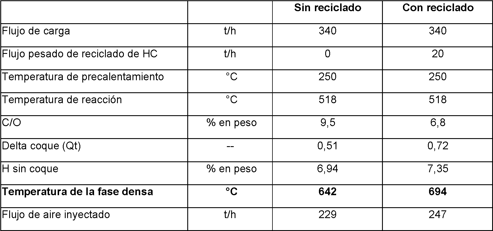
En la Tabla 6, se constata que la cantidad de coque aumenta en el catalizador (Qt varía de 0,51 a 0,72) y que la temperatura demasiado baja de la unidad sin reciclaje aumenta hasta más de 690 °C, asegurando así el re-equilibrio del balance térmico de la unidad. In Table 6, it is verified that the amount of coke increases in the catalyst (Qt varies from 0.51 to 0.72) and that the too low temperature of the unit without recycling increases to more than 690 ° C, thus ensuring the rebalancing the thermal balance of the unit.
Claims (15)

Applications Claiming Priority (2)
| Application Number | Priority Date | Filing Date | Title |
|---|---|---|---|
| FR1061287A FR2969643B1 (en) | 2010-12-27 | 2010-12-27 | CATALYTIC CRACKING PROCESS FOR TREATING A LOW CARBON CONRADSON CUT |
| PCT/FR2011/052912 WO2012089952A1 (en) | 2010-12-27 | 2011-12-09 | Catalytic cracking method for treating a fraction having a low amount of conradson carbon |
Publications (1)
| Publication Number | Publication Date |
|---|---|
| ES2746526T3 true ES2746526T3 (en) | 2020-03-06 |
Family
ID=43981425
Family Applications (1)
| Application Number | Title | Priority Date | Filing Date |
|---|---|---|---|
| ES11811059T Active ES2746526T3 (en) | 2010-12-27 | 2011-12-09 | Catalytic cracking procedure for the treatment of a low carbon content Conradson |
Country Status (8)
| Country | Link |
|---|---|
| US (2) | US9657233B2 (en) |
| EP (1) | EP2658950B1 (en) |
| JP (1) | JP6322412B2 (en) |
| KR (1) | KR101908540B1 (en) |
| ES (1) | ES2746526T3 (en) |
| FR (1) | FR2969643B1 (en) |
| RU (1) | RU2605547C2 (en) |
| WO (1) | WO2012089952A1 (en) |
Families Citing this family (9)
| Publication number | Priority date | Publication date | Assignee | Title |
|---|---|---|---|---|
| KR101771163B1 (en) * | 2016-02-01 | 2017-08-24 | 한국기계연구원 | Catalyst regenerator and regenerating method thereof |
| CN108854866B (en) * | 2017-05-10 | 2020-10-20 | 中国石油集团东北炼化工程有限公司吉林设计院 | Distributor and top cap thereof |
| JP7457659B2 (en) * | 2018-05-24 | 2024-03-28 | ティー.イーエヌ プロセス テクノロジー, インク. | Stripper and packing device |
| KR102121986B1 (en) * | 2018-07-11 | 2020-06-26 | 한국기계연구원 | Multistage combustion type of catalyst regenerator and regeneration method thereof |
| US11167258B2 (en) * | 2019-05-14 | 2021-11-09 | Uop Llc | Apparatus and process for separating gases from catalyst and revamp |
| FR3104470A1 (en) * | 2019-12-12 | 2021-06-18 | IFP Energies Nouvelles | Device and process for gas-solid separation of catalytic cracking in a fluidized bed with internal pressure drop. |
| FR3104467A1 (en) * | 2019-12-12 | 2021-06-18 | IFP Energies Nouvelles | Device and process for gas-solid separation of catalytic cracking in fluidized bed with deflector under window |
| BR102020016971A2 (en) * | 2020-08-20 | 2022-03-03 | Petróleo Brasileiro S.A. - Petrobras | Process for obtaining aromatics and aromatic stream |
| FR3123361A1 (en) * | 2021-05-31 | 2022-12-02 | IFP Energies Nouvelles | Device and process for catalytic cracking with heat input for the treatment of low coking feedstocks. |
Family Cites Families (14)
| Publication number | Priority date | Publication date | Assignee | Title |
|---|---|---|---|---|
| US3812029A (en) * | 1972-10-13 | 1974-05-21 | Mobil Oil Corp | Device for injecting easily coked fluids into a high temperature vessel |
| US3856659A (en) | 1972-12-19 | 1974-12-24 | Mobil Oil Corp | Multiple reactor fcc system relying upon a dual cracking catalyst composition |
| AU580617B2 (en) * | 1984-09-10 | 1989-01-19 | Mobil Oil Corporation | Process for visbreaking resids in the presence of hydrogen- donor materials and organic sulfur compounds |
| US4684756A (en) | 1986-05-01 | 1987-08-04 | Mobil Oil Corporation | Process for upgrading wax from Fischer-Tropsch synthesis |
| US4888103A (en) | 1986-09-03 | 1989-12-19 | Herbst Joseph A | Process of stripping in a catalytic cracking operation employing a catalyst mixture which includes a shape selective medium pore silicate zeolite component |
| FR2728805B1 (en) * | 1994-12-29 | 1997-03-28 | Total Raffinage Distribution | METHOD AND DEVICE FOR STRIPPING FLUIDIZED SOLIDS AND USE IN A FLUID STATE CRACKING PROCESS |
| RU2092522C1 (en) * | 1995-06-30 | 1997-10-10 | Александр Михайлович Окружнов | Method and apparatus for processing hydrocarbon raw material |
| FR2757785B1 (en) * | 1996-12-31 | 1999-11-26 | Total Raffinage Distribution | DEVICE FOR THE TREATMENT OF SOLID PARTICLES IN A FLUIDIZED BED, AND ITS USE |
| US6224833B1 (en) | 1998-12-15 | 2001-05-01 | Koch-Glitsch, Inc. | Apparatus for contacting of gases and solids in fluidized beds |
| US7022221B1 (en) * | 2002-08-16 | 2006-04-04 | Uop Llc | Stripping apparatus and process |
| US7077997B1 (en) | 2002-08-16 | 2006-07-18 | Uop Llc | Stripping apparatus |
| CN1332747C (en) | 2004-10-22 | 2007-08-22 | 中国石油化工股份有限公司 | Internal structure of FCC stripper and its arrangement method |
| JP5388583B2 (en) | 2006-02-13 | 2014-01-15 | ユーオーピー エルエルシー | Peeling apparatus and method |
| US7767075B2 (en) * | 2007-12-21 | 2010-08-03 | Uop Llc | System and method of producing heat in a fluid catalytic cracking unit |
-
2010
- 2010-12-27 FR FR1061287A patent/FR2969643B1/en active Active
-
2011
- 2011-12-09 JP JP2013545461A patent/JP6322412B2/en active Active
- 2011-12-09 RU RU2013132972/04A patent/RU2605547C2/en active
- 2011-12-09 KR KR1020137017463A patent/KR101908540B1/en active IP Right Grant
- 2011-12-09 WO PCT/FR2011/052912 patent/WO2012089952A1/en active Application Filing
- 2011-12-09 US US13/879,717 patent/US9657233B2/en active Active
- 2011-12-09 EP EP11811059.2A patent/EP2658950B1/en active Active
- 2011-12-09 ES ES11811059T patent/ES2746526T3/en active Active
-
2015
- 2015-12-16 US US14/971,322 patent/US9719026B2/en active Active
Also Published As
| Publication number | Publication date |
|---|---|
| WO2012089952A1 (en) | 2012-07-05 |
| JP6322412B2 (en) | 2018-05-09 |
| RU2013132972A (en) | 2015-02-10 |
| KR101908540B1 (en) | 2018-10-17 |
| EP2658950B1 (en) | 2019-07-17 |
| US20130292302A1 (en) | 2013-11-07 |
| KR20140037801A (en) | 2014-03-27 |
| US9657233B2 (en) | 2017-05-23 |
| FR2969643B1 (en) | 2014-11-21 |
| JP2014501832A (en) | 2014-01-23 |
| RU2605547C2 (en) | 2016-12-20 |
| US9719026B2 (en) | 2017-08-01 |
| US20160101397A1 (en) | 2016-04-14 |
| EP2658950A1 (en) | 2013-11-06 |
| FR2969643A1 (en) | 2012-06-29 |
Similar Documents
| Publication | Publication Date | Title |
|---|---|---|
| ES2746526T3 (en) | Catalytic cracking procedure for the treatment of a low carbon content Conradson | |
| US8753502B1 (en) | Using low carbon fuel with a catalyst charge heater | |
| US8354065B1 (en) | Catalyst charge heater | |
| EP2737013B1 (en) | Fluidized catalytic cracking of paraffinic naphtha in a downflow reactor | |
| ES2626677T3 (en) | Catalytic cracking method suitable for the treatment of Conradson low carbon loads comprising the recycling of a coking fraction according to a new technology | |
| CN105849235B (en) | A kind of catalytic cracking reaction renovation process | |
| US7935245B2 (en) | System and method of increasing synthesis gas yield in a fluid catalytic cracking unit | |
| US11060038B2 (en) | Catalytic cracking method for treating a fraction having a low amount of conradson carbon | |
| ES2772139T3 (en) | Multi-phase cracking and extraction procedure in an FCC unit | |
| US8618011B2 (en) | Systems and methods for regenerating a spent catalyst | |
| BR112014001781B1 (en) | system configured for the production of at least one product | |
| US20080153689A1 (en) | System and method of reducing carbon dioxide emissions in a fluid catalytic cracking unit | |
| US20160362613A1 (en) | Fluid catalytic cracking with supplemental heat | |
| AU2008261139A1 (en) | Method and system of heating a fluid catalytic cracking unit for overall CO2 reduction | |
| US7767075B2 (en) | System and method of producing heat in a fluid catalytic cracking unit | |
| CN112423874B (en) | Utilizing multiple catalyst reactions and regenerations to maximize olefin production | |
| Avidan et al. | Fluid-catalytic cracking-past and future challenges | |
| US20150136647A1 (en) | Reactor and main fractionator configuration for producing diesel | |
| CN111655363B (en) | Method and apparatus for fluidizing a catalyst bed | |
| CN104379702B (en) | Utilize the equipment of insert two strands of catalyst streams of mixing of the opening with alignment | |
| MX2008009843A (en) | Process for recovering power from fcc product. | |
| CN109609176A (en) | A kind of descending-bed reactor method for catalytic conversion of heavy oil and its device | |
| BENZ et al. | Petroleum Refinery of the Future 233 This material appeared in Chemical Engineering Progress, pp. 21–27, October 1986, copyright© 1986 by AIChE, and is reprinted with special permission. | |
| JPH0471957B2 (en) |