ES2708994T3 - Parameter adjustment method of PI and PID controllers - Google Patents
Parameter adjustment method of PI and PID controllers Download PDFInfo
- Publication number
- ES2708994T3 ES2708994T3 ES12755927T ES12755927T ES2708994T3 ES 2708994 T3 ES2708994 T3 ES 2708994T3 ES 12755927 T ES12755927 T ES 12755927T ES 12755927 T ES12755927 T ES 12755927T ES 2708994 T3 ES2708994 T3 ES 2708994T3
- Authority
- ES
- Spain
- Prior art keywords
- controller
- gain
- controlled
- proportional
- tosc
- Prior art date
- Legal status (The legal status is an assumption and is not a legal conclusion. Google has not performed a legal analysis and makes no representation as to the accuracy of the status listed.)
- Active
Links
Classifications
-
- G—PHYSICS
- G05—CONTROLLING; REGULATING
- G05B—CONTROL OR REGULATING SYSTEMS IN GENERAL; FUNCTIONAL ELEMENTS OF SUCH SYSTEMS; MONITORING OR TESTING ARRANGEMENTS FOR SUCH SYSTEMS OR ELEMENTS
- G05B11/00—Automatic controllers
- G05B11/01—Automatic controllers electric
-
- G—PHYSICS
- G05—CONTROLLING; REGULATING
- G05B—CONTROL OR REGULATING SYSTEMS IN GENERAL; FUNCTIONAL ELEMENTS OF SUCH SYSTEMS; MONITORING OR TESTING ARRANGEMENTS FOR SUCH SYSTEMS OR ELEMENTS
- G05B6/00—Internal feedback arrangements for obtaining particular characteristics, e.g. proportional, integral or differential
- G05B6/02—Internal feedback arrangements for obtaining particular characteristics, e.g. proportional, integral or differential electric
-
- G—PHYSICS
- G05—CONTROLLING; REGULATING
- G05B—CONTROL OR REGULATING SYSTEMS IN GENERAL; FUNCTIONAL ELEMENTS OF SUCH SYSTEMS; MONITORING OR TESTING ARRANGEMENTS FOR SUCH SYSTEMS OR ELEMENTS
- G05B11/00—Automatic controllers
- G05B11/01—Automatic controllers electric
- G05B11/36—Automatic controllers electric with provision for obtaining particular characteristics, e.g. proportional, integral, differential
- G05B11/42—Automatic controllers electric with provision for obtaining particular characteristics, e.g. proportional, integral, differential for obtaining a characteristic which is both proportional and time-dependent, e.g. P. I., P. I. D.
Landscapes
- Physics & Mathematics (AREA)
- General Physics & Mathematics (AREA)
- Engineering & Computer Science (AREA)
- Automation & Control Theory (AREA)
- Feedback Control In General (AREA)
Abstract
Métodos de ajuste de los parámetros de un controlador PI en el sistema de control de bucle cerrado de un objeto, cuya función de transferencia puede aproximarse como un filtro de primer orden con constante de tiempo T y tiempo muerto L, y ganancia conocida k, que comprende las etapas de: a. conectar en serie la entrada del objeto controlado con la salida de la parte integral del controlador cuya parte proporcional está desconectada, estableciendo el menor valor de ganancia y cerrando el bucle de control, b. aumentar la ganancia del controlador hasta el límite de estabilidad con oscilaciones estables de la variable controlada y describir el período de las oscilaciones Tosc y el valor fijo de la ganancia del controlador kU, c. calcular el retardo de primer orden T del modelo del sistema controlado utilizando la siguiente fórmula **Fórmula** donde ωosc = 2π/Tosc y el coeficiente **Fórmula**donde el L es el tiempo muerto del modelo del sistema d. calcular la configuración del controlador PI a partir de la siguiente fórmula **Fórmula** y determinar la configuración física del controlador PI real a partir de las relaciones **Fórmula** donde kpN es la ganancia del controlador proporcional y TiN es la constante de tiempo del controlador integral.Parameter adjustment methods of a PI controller in the closed-loop control system of an object, whose transfer function can be approximated as a first-order filter with time constant T and dead time L, and known gain k, which It includes the stages of: a. connect the input of the controlled object in series with the output of the integral part of the controller whose proportional part is disconnected, establishing the lowest gain value and closing the control loop, b. increase the controller gain to the stability limit with stable oscillations of the controlled variable and describe the period of the oscillations Tosc and the fixed value of the controller gain kU, c. Calculate the first order delay T of the controlled system model using the following formula **Formula** where ωosc = 2π/Tosc and the coefficient **Formula**where L is the dead time of the system model d. calculate the PI controller configuration from the following formula **Formula** and determine the physical configuration of the actual PI controller from the relationships **Formula** where kpN is the gain of the proportional controller and TiN is the constant of integral controller time.
Description
DESCRIPCIONDESCRIPTION
Metodo de ajuste de parametros de controladores PI y PIDPI and PID controller parameters adjustment method
El objeto de la invencion es el metodo de ajuste de parametros de controladores PI y PID.The object of the invention is the method of adjusting parameters of PI and PID controllers.
Existen muchos metodos de ajuste conocidos de los parametros de controladores PI y PID recopilados en el libro de O'Dwyer: Handbook of PI and PID Controller the Engine tuning Rules, Imperial College Press, 2006. La metodologfa de ajuste de PI y PID se basa en procedimientos que han sido elaborados por Ziegler y Nichols (Ziegler J.G., Nichols N.B.: The optimum Setting the odds Automatic Controllers, ASME, Rochester, N. Y., 1942). Existen dos procedimientos: el primero se denomina metodo de respuesta en frecuencia y el segundo metodo de respuesta a escalon.There are many known adjustment methods of the PI and PID controller parameters collected in O'Dwyer's book: Handbook of PI and PID Controller, Engine Tuning Rules, Imperial College Press, 2006. The PI and PID adjustment methodology is based in procedures that have been elaborated by Ziegler and Nichols (Ziegler JG, Nichols NB: The Optimal Setting of the Odds Automatic Controllers, ASME, Rochester, NY, 1942). There are two procedures: the first is called the frequency response method and the second step response method.
El metodo de frecuencia se basa en el analisis de propiedades del sistema de control de bucle cerrado (sistema de control accionado por error) que se encuentra en el lfmite de estabilidad. El controlador proporcional P se utiliza en la primera etapa de este procedimiento de ajuste. Su ganancia aumenta hasta lograr oscilaciones sostenidas de la senal controlada. Despues se evalua la ganancia del controlador proporcional y el penodo de oscilacion del sistema de bucle cerrado. Estos valores se utilizan para determinar la configuracion del controlador PI y PID.The frequency method is based on the analysis of properties of the closed loop control system (error-controlled control system) that is in the stability limit. The proportional controller P is used in the first stage of this adjustment procedure. Its gain increases until sustained oscillations of the controlled signal. Then the gain of the proportional controller and the oscillation period of the closed loop system are evaluated. These values are used to determine the configuration of the PI and PID controller.
El metodo de respuesta a escalon se basa en una estimacion aproximada de los parametros modelo del sistema controlado. El filtro de primer orden con tiempo muerto es el modelo de estimacion. Los ajustes de los controladores PI o PID que funcionan en el sistema de control de realimentacion se calculan en base a los valores estimados. Se calcularon las propiedades del controlador para el controlador P. La sustitucion del controlador P por los controladores PI o PID vana las caractensticas del sistema de control. Esto dificulta la seleccion de la configuracion correcta del controlador que garantiza el correcto funcionamiento del sistema de control. Las primeras etapas de los procedimientos de ajuste no identifican con precision la dinamica del sistema controlado. Es por esto que los ajustes propuestos por estos procedimientos no aseguran la forma de onda transitoria adecuada.The step response method is based on an approximate estimate of the model parameters of the controlled system. The first order filter with dead time is the estimation model. The settings of the PI or PID controllers that work in the feedback control system are calculated based on the estimated values. The properties of the controller for the P controller were calculated. The substitution of the P controller by the PI or PID controllers will vary the characteristics of the control system. This makes it difficult to select the correct configuration of the controller that guarantees the correct functioning of the control system. The early stages of the adjustment procedures do not accurately identify the dynamics of the controlled system. This is why the adjustments proposed by these procedures do not ensure the appropriate transient waveform.
Existen tambien metodos conocidos que utilizan las partes proporcionales e integrales del controlador durante la etapa de identificacion, por ejemplo. Utkal Mehta y otros "On-line Identification and Control Methods for PID Controllers", 2010 11th Int. Conf. Control, Automation, Robotics and Vision, Singapur, 7-10 de diciembre de 2010, Luo y otros, "System and method for closed loop auto-tuning of PID controllers" US6081751, 27 de Jun. 2000. Estos no proporcionan una calidad de control satisfactoria. Ello viene provocado por los procedimientos de identificacion que no tienen en cuenta el criterio de calidad de control adecuado. Por lo tanto, es crucial utilizar el mdice de calidad de control adecuado y formular las formulas que garanticen un proceso de control optimo. Esto hace que estas formulas sean parte integral del procedimiento de ajuste del controlador. Existen tambien metodos conocidos que utilizan el controlador on-off para lograr una oscilacion de la senal controlada durante una etapa de identificacion (Wojsznis y otros, "System and method for automatically tuning a process controller", US5453925, 26 de Sep. 1995). Esto hace posible obtener una senal controlada oscilante para los sistemas controlados de orden inferior. Este enfoque tiene inconvenientes. En algunos aspectos, el controlador on-off tiene caractensticas similares a las del controlador proporcional, por lo que hace diffcil encontrar parametros apropiados que sean adecuados para el controlador final, como el controlador PI o PID. Otro inconveniente es la necesidad de desconectar el bucle del sistema de control para cambiar el controlador para pasar del controlador on-off al controlador final. Esto puede ser peligroso para el sistema controlado.There are also known methods that use the proportional and integral parts of the controller during the identification stage, for example. Utkal Mehta and others "On-line Identification and Control Methods for PID Controllers", 2010 11th Int. Conf. Control, Automation, Robotics and Vision, Singapore, December 7-10, 2010, Luo et al., "System and method for closed loop auto-tuning of PID controllers " US6081751, June 27, 2000. These do not provide satisfactory quality control. This is caused by the identification procedures that do not take into account the appropriate quality control criteria. Therefore, it is crucial to use the appropriate quality control index and formulate the formulas that guarantee an optimal control process. This makes these formulas an integral part of the controller adjustment procedure. There are also known methods that use the on-off controller to achieve a controlled oscillation of the signal during an identification stage (Wojsznis et al., "System and method for automatic tuning to process controller", US5453925, Sep 26, 1995). This makes it possible to obtain an oscillating controlled signal for lower order controlled systems. This approach has drawbacks. In some aspects, the on-off controller has features similar to those of the proportional controller, making it difficult to find appropriate parameters that are suitable for the final controller, such as the PI or PID controller. Another drawback is the need to disconnect the loop from the control system to change the controller to switch from the on-off controller to the final controller. This can be dangerous for the controlled system.
Tambien se conocen los metodos de ajuste del controlador basados en el analisis de las caractensticas de frecuencia (Y. lino, T. Shigemasa: Control system and method for deterministic control parameters of plants, US5172312). Esos metodos requieren una determinacion mas temprana de la caractenstica de frecuencia, lo cual puede ser inconveniente y requerir mucho tiempo.Also known are the adjustment methods of the controller based on the analysis of the frequency characteristics (Y. flax, T. Shigemasa: Control system and method for deterministic control parameters of plants, US5172312). These methods require an earlier determination of the frequency characteristic, which can be inconvenient and time-consuming.
El progreso de la tecnologfa informatica permite desarrollar un metodo numerico de parametros de ajuste del controlador que sean optimos en el sentido del criterio seleccionado. Los criterios pueden formularse mediante el uso de formulas analfticas conocidas y de uso frecuente, tales como el criterio ITAE (A. E. Awouda, R. B. Mamat: New PID tuning rule using ITAE criteria, IJE, 2010). El criterio de optimalidad tambien puede formularse mediante ecuaciones que solo pueden resolverse mediante el uso de metodos de optimizacion numericos (R. Toscano: A Simple robust PI-PID controller design via numerical optimization approach, JPC, 2005). El conocimiento exacto de la dinamica del sistema controlado es el requisito previo para obtener parametros optimos del controlador. Esa dinamica a menudo se aproxima mediante un filtro de primer orden con modelo de tiempo muerto. La principal ventaja del modelo es un conjunto limitado de parametros, mientras que el inconveniente es una dinamica del sistema controlada excesivamente simplificada, especialmente para parametros del modelo identificados incorrectamente. Los metodos de ajuste mencionados anteriormente no incluyen la etapa de identificacion lo cual los hace inutiles. The progress of the computer technology allows the development of a numerical method of adjustment parameters of the controller that are optimal in the sense of the selected criterion. The criteria can be formulated through the use of known and frequently used analytical formulas, such as the ITAE criterion (AE Awouda, RB Mamat: New PID tuning rule using ITAE criteria, IJE, 2010). The optimality criterion can also be formulated by means of equations that can only be solved by the use of numerical optimization methods (R. Toscano: A Simple robust PI-PID controller design via numerical optimization approach, JPC, 2005). The exact knowledge of the dynamics of the controlled system is the prerequisite to obtain optimal parameters of the controller. This dynamic is often approximated by a first order filter with a dead time model. The main advantage of the model is a limited set of parameters, while the drawback is an oversimplified controlled system dynamics, especially for improperly identified model parameters. The adjustment methods mentioned above do not include the identification stage which renders them useless.
De acuerdo con la invencion, solo el controlador integral se anade al sistema controlado en la primera etapa del procedimiento de ajuste del controlador PI o PID, que es el filtro de primer orden con tiempo muerto. Esto significa que solamente se desconectan las partes proporcionales y diferenciales del controlador PID. Este es el rasgo distintivo de la invencion. Se supone que la ganancia proporcional k del sistema controlado en estado estacionario es conocida. En la siguiente etapa, la ganancia del controlador integral gana ki se aumenta para obtener una oscilacion sostenida con penodo constante. Cuando el sistema de control de bucle cerrado se encuentra en el lfmite de estabilidad, se evalua la ganancia maxima del controlador ku y el periodo de oscilacion ToSc. La formula: T = According to the invention, only the integral controller is added to the controlled system in the first stage of the adjustment procedure of the PI or PID controller, which is the first order filter with dead time. This means that only the proportional and differential parts of the PID controller are disconnected. This is the distinctive feature of the invention. It is assumed that the proportional gain k of the steady state controlled system is known. In the next stage, the gain of the integral controller gain ki is increased to obtain a sustained oscillation with constant delay. When the closed loop control system is at the stability limit, the maximum gain of the controller ku and the period of oscillation ToSc is evaluated. The formula: T =


definen las propiedades del modelo del controlador. Las propiedades del controlador se calculan a partir dedefine the properties of the controller model. Controller properties are calculated from

donde kpN es la ganancia del controlador proporcional y T,n es la constante de tiempo del controlador integral.where kpN is the gain of the proportional controller and T, n is the time constant of the integral controller.
Solo se anade al sistema el controlador integral controlado en la primera etapa del procedimiento de ajuste de la invencion para el controlador de tipo PID, que es el filtro de primer orden con tiempo muerto (la parte del controlador PID proporcional y derivada se desconectan, solo la parte integral es activa). Se trata de una caractenstica distintiva de esta invencion. Se supone que se conoce la ganancia proporcional del sistema controlado en estado estable, se trata del coeficiente k. A continuacion, la ganancia del controlador integral ki se cambia para llevar el sistema al lfmite de estabilidad. Entonces se evalua la maxima ganancia de controlador integral ku y el periodo de oscilacion T^c- La ^ formula:

definen las propiedades del modelo del controlador. Los parametros del controlador se calculan a partir dedefine the properties of the controller model. The controller parameters are calculated from

donde kpN es la ganancia del controlador proporcional, Tn es la constante de tiempo del controlador integral y TdN es la constante de tiempo del controlador derivativo.where kpN is the gain of the proportional controller, T n is the time constant of the integral controller and TdN is the time constant of the derivative controller.
Los supuestos del metodo de ajuste de la invencion son:The assumptions of the adjustment method of the invention are:
1. La ganancia proporcional del sistema controlado es conocida. Esta puede determinarse facilmente mediante el experimento de respuesta a escalon.1. The proportional gain of the controlled system is known. This can be easily determined by the step response experiment.
2. La dinamica del sistema controlado se aproxima de manera aceptable mediante el filtro de primer orden con tiempo muerto (modelo Kupfmuller):
En la primera etapa del procedimiento de la invencion, el sistema controlado se conecta en serie con el controlador de tipo integral con coeficiente de ganancia k. A continuacion, se incrementa la ganancia del controlador integral para que el sistema de control de bucle cerrado alcance el lfmite de estabilidad. En ese punto, se describe y se almacena el penodo de oscilacion sostenida del sistema de control Tosc y la ganancia maxima del controlador ku. In the first step of the method of the invention, the controlled system is connected in series with the integral type controller with gain coefficient k. Next, the gain of the integral controller is increased so that the closed-loop control system reaches the stability limit. At that point, the sustained oscillation period of the Tosc control system and the maximum gain of the ku controller are described and stored .
El sistema consiste en el controlador integral conectado en serie y el filtro de primer orden con tiempo muerto. La constante de tiempo del filtro de primer orden del modelo del sistema controlado se estima utilizando la formula:The system consists of the integral controller connected in series and the first order filter with dead time. The time constant of the first order filter of the controlled system model is estimated using the formula:
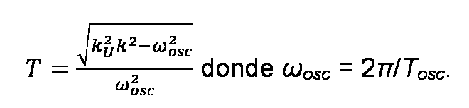
El coeficiente 9 = ^ = (arcctg(u0SCT ))/(u0SCT), definido como el cociente del retardo de primer orden T y el tiempo muerto L, se calcula a partir del cambio de fase del modelo de aproximacion del sistema de control de bucle abierto. El ajuste de los modelos de controladores de tipo PI y PID se calculo como optimo segun el criterio ITAE (integral del producto de tiempo y el error de control absoluto del sistema de bucle cerrado).The coefficient 9 = ^ = ( arcctg (u0SCT)) / (u0SCT ), defined as the quotient of the first order delay T and the dead time L, is calculated from the phase change of the approximation model of the control system of open loop. The adjustment of the PI and PID type controller models was calculated as optimal according to the ITAE criterion (integral of the time product and the absolute control error of the closed loop system).
El ajuste optimo de los controladores PI y PID se calculo en funcion del coeficiente 9. Introduccion del coeficiente 9 facilita el calculo, debido a la disminucion del numero de variables de entrada. Los ajustes de tiempo de los controladores no tienen dimensiones y estan relacionados con la constante de tiempo del filtro de primer orden del objeto de control T. The optimal setting of the PI and PID controllers was calculated as a function of the coefficient 9. Introduction of the coefficient 9 facilitates the calculation, due to the decrease in the number of input variables. The time settings of the controllers have no dimensions and are related to the time constant of the first order filter of the control object T.
Las configuraciones optimas (de acuerdo con el criterio ITAE) del controlador PID se aproximan mediante las siguientes formulas:The optimal configurations (according to the ITAE criterion) of the PID controller are approximated by the following formulas:

Para el controlador PI, las configuraciones optimas de acuerdo con el criterio ITAE se aproximan mediante formulas:For the PI controller, the optimal configurations according to the ITAE criteria are approximated by formulas:

Dado que las propiedades del modelo de controlador estan relacionadas con los coeficientes del modelo del sistema controlado, la configuracion real del controlador debe calcularse mediante las siguientes formulas:Since the properties of the controller model are related to the coefficients of the controlled system model, the actual configuration of the controller must be calculated using the following formulas:

donde kpN es la ganancia del controlador proporcional, T,n es la constante de tiempo del controlador integral y TdN es la constante de tiempo del controlador derivado.where kpN is the gain of the proportional controller, T, n is the time constant of the integral controller and TdN is the time constant of the derived controller.
El objeto de esta invencion se presenta en las siguientes seis figuras. La figura 1 muestra el diagrama de bloques del sistema de control. Las figuras 2 a 5 muestran las respuestas a escalon del sistema de control de bucle cerrado obtenidas para los metodos de la invencion y de Ziegler-Nichols. La ganancia del sistema controlado es igual a 1. La figura 2 muestra las respuestas a escalon del sistema con el controlador PID y 9 = 0,2. La figura 3 muestra las respuestas a escalon del sistema con el controlador PID y 9 = 2. La figura 4 muestra las respuestas a escalon del sistema con el controlador PI y 9 = 0,2. La figura 5 muestra las respuestas a escalon del sistema con el controlador PI y 9 = 0,2.The object of this invention is presented in the following six figures. Figure 1 shows the block diagram of the control system. Figures 2 to 5 show the step responses of the closed loop control system obtained for the methods of the invention and Ziegler-Nichols. The gain of the controlled system is equal to 1. Figure 2 shows the system step responses with the PID controller and 9 = 0.2. Figure 3 shows the system step responses with the PID controller and 9 = 2. Figure 4 shows the system step responses with the PI controller and 9 = 0.2. Figure 5 shows the responses to step of the system with the PI controller and 9 = 0.2.
La configuracion del controlador PI se presenta en la Tabla 1. La configuracion del controlador PID se muestra en la Tabla 2.The configuration of the PI controller is presented in Table 1. The PID controller configuration is shown in Table 2.
Tabla 1 La confi uracion del controlador PI de acuerdo con ITAETable 1 The confi uration of the PI controller according to ITAE

Tabla 2. La confi uracion del controlador PID de acuerdo con ITAETable 2. The confi uration of the PID controller according to ITAE

El metodo de la invencion genera un menor sobreimpulso y oscilacion del valor controlado durante el transitorio (figura 2 a figura 5). Ademas, elimina el fenomeno adverso de una amortiguacion excesiva del valor controlado para un mayor coeficiente 9 y el controlador PI (figura 5). The method of the invention generates a smaller overshoot and oscillation of the value controlled during the transient (figure 2 to figure 5). In addition, it eliminates the adverse phenomenon of excessive damping of the controlled value for a higher coefficient 9 and the PI controller (Figure 5).
Claims (2)


Applications Claiming Priority (2)
| Application Number | Priority Date | Filing Date | Title |
|---|---|---|---|
| PL395033A PL222174B1 (en) | 2011-05-27 | 2011-05-27 | Method for tuning the parameters of continuous controllers of PI and PID types |
| PCT/PL2012/000036 WO2012165980A2 (en) | 2011-05-27 | 2012-05-28 | The tuning methods of the pi and pid controllers parameters |
Publications (1)
| Publication Number | Publication Date |
|---|---|
| ES2708994T3 true ES2708994T3 (en) | 2019-04-12 |
Family
ID=47260140
Family Applications (1)
| Application Number | Title | Priority Date | Filing Date |
|---|---|---|---|
| ES12755927T Active ES2708994T3 (en) | 2011-05-27 | 2012-05-28 | Parameter adjustment method of PI and PID controllers |
Country Status (5)
| Country | Link |
|---|---|
| US (1) | US20140081427A1 (en) |
| EP (1) | EP2715458B1 (en) |
| ES (1) | ES2708994T3 (en) |
| PL (1) | PL222174B1 (en) |
| WO (1) | WO2012165980A2 (en) |
Families Citing this family (14)
| Publication number | Priority date | Publication date | Assignee | Title |
|---|---|---|---|---|
| CN104834211A (en) * | 2015-04-29 | 2015-08-12 | 贵州电力试验研究院 | Thermal power plant control system internal model PID controller tuning method |
| CN107942648A (en) * | 2017-11-29 | 2018-04-20 | 中国飞机强度研究所 | A kind of extra space temperature field PID controller parameter setting method |
| CN108958021A (en) * | 2018-07-07 | 2018-12-07 | 江苏迅达电磁线有限公司 | A kind of design method of the linear motor PID controller of industrial robot |
| CN110520803B (en) * | 2018-08-10 | 2022-10-18 | 曾喆昭 | Intelligent PID control method |
| CN109116738B (en) * | 2018-09-27 | 2021-04-13 | 杭州电子科技大学 | An analytical method for two-degree-of-freedom internal model control of an industrial heating furnace |
| US11467543B2 (en) * | 2019-09-20 | 2022-10-11 | Fisher-Rosemount Systems, Inc. | Process controller design with process approximation and lambda tuning |
| CN112835286B (en) * | 2020-11-27 | 2023-02-17 | 江西理工大学 | PID parameter automatic tuning method and system |
| CN114019786B (en) * | 2021-09-29 | 2024-09-24 | 国家能源集团科学技术研究院有限公司 | A control system and parameter setting method for switching PI to PID online |
| CN114859699B (en) * | 2022-05-09 | 2024-06-07 | 广东电网有限责任公司 | Design method, device, equipment and medium of acceleration type engineering fastest controller |
| CN115808872B (en) * | 2022-11-25 | 2025-08-05 | 成都市运泰利自动化设备有限公司 | A PID parameter self-tuning algorithm for temperature control |
| PL447205A1 (en) * | 2023-12-21 | 2025-06-23 | Politechnika Morska W Szczecinie | Method of controlling the regulated object |
| PL447206A1 (en) * | 2023-12-21 | 2025-06-23 | Politechnika Morska W Szczecinie | PID type controller |
| CN121069731B (en) * | 2025-08-22 | 2026-07-17 | 国家能源集团科学技术研究院有限公司 | PI controller separation parameter setting method and device |
| CN121325558B (en) * | 2025-10-24 | 2026-07-07 | 国家能源集团科学技术研究院有限公司 | Proportional-integral controller setting method with filter |
Family Cites Families (4)
| Publication number | Priority date | Publication date | Assignee | Title |
|---|---|---|---|---|
| JP2755644B2 (en) * | 1989-01-20 | 1998-05-20 | 株式会社東芝 | Control system design method and design support device |
| US5453925A (en) * | 1993-05-28 | 1995-09-26 | Fisher Controls International, Inc. | System and method for automatically tuning a process controller |
| US5587899A (en) * | 1994-06-10 | 1996-12-24 | Fisher-Rosemount Systems, Inc. | Method and apparatus for determining the ultimate gain and ultimate period of a controlled process |
| US6081751A (en) * | 1997-12-19 | 2000-06-27 | National Instruments Corporation | System and method for closed loop autotuning of PID controllers |
-
2011
- 2011-05-27 PL PL395033A patent/PL222174B1/en unknown
-
2012
- 2012-05-28 WO PCT/PL2012/000036 patent/WO2012165980A2/en not_active Ceased
- 2012-05-28 ES ES12755927T patent/ES2708994T3/en active Active
- 2012-05-28 EP EP12755927.6A patent/EP2715458B1/en not_active Not-in-force
- 2012-05-28 US US14/123,013 patent/US20140081427A1/en not_active Abandoned
Also Published As
| Publication number | Publication date |
|---|---|
| EP2715458B1 (en) | 2018-11-14 |
| WO2012165980A4 (en) | 2013-03-07 |
| WO2012165980A2 (en) | 2012-12-06 |
| WO2012165980A3 (en) | 2013-01-24 |
| US20140081427A1 (en) | 2014-03-20 |
| EP2715458A2 (en) | 2014-04-09 |
| PL395033A1 (en) | 2011-11-21 |
| PL222174B1 (en) | 2016-07-29 |
Similar Documents
| Publication | Publication Date | Title |
|---|---|---|
| WO2012165980A2 (en) | The tuning methods of the pi and pid controllers parameters | |
| Berner et al. | Improved relay autotuning using normalized time delay | |
| Levy et al. | PID autotuning using relay feedback | |
| Arrieta et al. | Simple PID tuning rules with guaranteed Ms robustness achievement | |
| JP5585381B2 (en) | Auto tuning device and auto tuning method | |
| Antony et al. | Comparison of performance indices of PID controller with different tuning methods | |
| Holkar et al. | Sliding mode control with predictive PID sliding surface for improved performance | |
| Ozdemir et al. | A new approach for calculation of PID parameters with model based compact form formulations | |
| Alfaro et al. | Model reference based robust tuning of five-parameter 2DoF PID controllers for first-order plus dead-time models | |
| Sánchez et al. | Nash tuning for optimal balance of the servo/regulation operation in robust PID control | |
| Singh et al. | Performance analysis of improving stability using tuned PID and Hybrid controllers | |
| Dziwiński et al. | Robust non-integer order controller for air heating process trainer | |
| CN102944995A (en) | Servo system controller and control method | |
| Dasari et al. | Simple method of calculating dynamic set-point weighting parameters for time delayed unstable processes | |
| Luan et al. | Parameter optimization of pressurizer level control system in nuclear power plant using relay feedback method | |
| Gopinath | Design of fractional order controllers for first order plus time delay systems | |
| Łaskawski et al. | Influence of sampling on the tuning of PID controller parameters | |
| RU2568386C2 (en) | Method for self-tuning of pid control system | |
| Hornychová et al. | Relay Feedback Identification Method for PID Controller Tuning | |
| Rahul et al. | Design of fractional order PI controller for first order plus dead time process based on maximum sensitivity | |
| JP2018077663A (en) | Plant control adjustment device | |
| Martinez et al. | Model reference PI controller tuning for second order inverse response and dead time processes | |
| Vásquez et al. | Comparison of PID methods for networked control systems | |
| Kula | On-line autotuning of PID controller for desired closed-loop response | |
| Atiç et al. | Generalized stability boundary locus for PI controller design for controlling integrating processes with dead time |