EP4583531A1 - Elektronische vorrichtung und verfahren zur ausgabe eines tonsignals und nichttransitorisches speichermedium - Google Patents
Elektronische vorrichtung und verfahren zur ausgabe eines tonsignals und nichttransitorisches speichermedium Download PDFInfo
- Publication number
- EP4583531A1 EP4583531A1 EP23868509.3A EP23868509A EP4583531A1 EP 4583531 A1 EP4583531 A1 EP 4583531A1 EP 23868509 A EP23868509 A EP 23868509A EP 4583531 A1 EP4583531 A1 EP 4583531A1
- Authority
- EP
- European Patent Office
- Prior art keywords
- sound output
- output device
- wearing
- reception
- signal
- Prior art date
- Legal status (The legal status is an assumption and is not a legal conclusion. Google has not performed a legal analysis and makes no representation as to the accuracy of the status listed.)
- Pending
Links
Images





Classifications
-
- H—ELECTRICITY
- H04—ELECTRIC COMMUNICATION TECHNIQUE
- H04R—LOUDSPEAKERS, MICROPHONES, GRAMOPHONE PICK-UPS OR LIKE ACOUSTIC ELECTROMECHANICAL TRANSDUCERS; ELECTRIC HEARING AIDS; PUBLIC ADDRESS SYSTEMS
- H04R1/00—Details of transducers, loudspeakers or microphones
- H04R1/10—Earpieces; Attachments therefor ; Earphones; Monophonic headphones
- H04R1/1058—Manufacture or assembly
- H04R1/1075—Mountings of transducers in earphones or headphones
-
- H—ELECTRICITY
- H04—ELECTRIC COMMUNICATION TECHNIQUE
- H04R—LOUDSPEAKERS, MICROPHONES, GRAMOPHONE PICK-UPS OR LIKE ACOUSTIC ELECTROMECHANICAL TRANSDUCERS; ELECTRIC HEARING AIDS; PUBLIC ADDRESS SYSTEMS
- H04R5/00—Stereophonic arrangements
- H04R5/04—Circuit arrangements, e.g. for selective connection of amplifier inputs/outputs to loudspeakers, for loudspeaker detection, or for adaptation of settings to personal preferences or hearing impairments
-
- G—PHYSICS
- G01—MEASURING; TESTING
- G01P—MEASURING LINEAR OR ANGULAR SPEED, ACCELERATION, DECELERATION, OR SHOCK; INDICATING PRESENCE, ABSENCE, OR DIRECTION, OF MOVEMENT
- G01P15/00—Measuring acceleration; Measuring deceleration; Measuring shock, i.e. sudden change of acceleration
-
- G—PHYSICS
- G06—COMPUTING OR CALCULATING; COUNTING
- G06F—ELECTRIC DIGITAL DATA PROCESSING
- G06F18/00—Pattern recognition
-
- H—ELECTRICITY
- H04—ELECTRIC COMMUNICATION TECHNIQUE
- H04R—LOUDSPEAKERS, MICROPHONES, GRAMOPHONE PICK-UPS OR LIKE ACOUSTIC ELECTROMECHANICAL TRANSDUCERS; ELECTRIC HEARING AIDS; PUBLIC ADDRESS SYSTEMS
- H04R1/00—Details of transducers, loudspeakers or microphones
- H04R1/10—Earpieces; Attachments therefor ; Earphones; Monophonic headphones
- H04R1/1041—Mechanical or electronic switches, or control elements
-
- H—ELECTRICITY
- H04—ELECTRIC COMMUNICATION TECHNIQUE
- H04R—LOUDSPEAKERS, MICROPHONES, GRAMOPHONE PICK-UPS OR LIKE ACOUSTIC ELECTROMECHANICAL TRANSDUCERS; ELECTRIC HEARING AIDS; PUBLIC ADDRESS SYSTEMS
- H04R3/00—Circuits for transducers
- H04R3/005—Circuits for transducers for combining the signals of two or more microphones
-
- H—ELECTRICITY
- H04—ELECTRIC COMMUNICATION TECHNIQUE
- H04R—LOUDSPEAKERS, MICROPHONES, GRAMOPHONE PICK-UPS OR LIKE ACOUSTIC ELECTROMECHANICAL TRANSDUCERS; ELECTRIC HEARING AIDS; PUBLIC ADDRESS SYSTEMS
- H04R3/00—Circuits for transducers
- H04R3/02—Circuits for transducers for preventing acoustic reaction, i.e. acoustic oscillatory feedback
-
- H—ELECTRICITY
- H04—ELECTRIC COMMUNICATION TECHNIQUE
- H04R—LOUDSPEAKERS, MICROPHONES, GRAMOPHONE PICK-UPS OR LIKE ACOUSTIC ELECTROMECHANICAL TRANSDUCERS; ELECTRIC HEARING AIDS; PUBLIC ADDRESS SYSTEMS
- H04R5/00—Stereophonic arrangements
- H04R5/027—Spatial or constructional arrangements of microphones, e.g. in dummy heads
-
- H—ELECTRICITY
- H04—ELECTRIC COMMUNICATION TECHNIQUE
- H04R—LOUDSPEAKERS, MICROPHONES, GRAMOPHONE PICK-UPS OR LIKE ACOUSTIC ELECTROMECHANICAL TRANSDUCERS; ELECTRIC HEARING AIDS; PUBLIC ADDRESS SYSTEMS
- H04R5/00—Stereophonic arrangements
- H04R5/033—Headphones for stereophonic communication
-
- H—ELECTRICITY
- H04—ELECTRIC COMMUNICATION TECHNIQUE
- H04R—LOUDSPEAKERS, MICROPHONES, GRAMOPHONE PICK-UPS OR LIKE ACOUSTIC ELECTROMECHANICAL TRANSDUCERS; ELECTRIC HEARING AIDS; PUBLIC ADDRESS SYSTEMS
- H04R29/00—Monitoring arrangements; Testing arrangements
- H04R29/001—Monitoring arrangements; Testing arrangements for loudspeakers
Definitions
- Various embodiments of the disclosure relate to an electronic device, a method, and a non-transitory storage medium for outputting a sound signal.
- Electronic devices are provided in various forms such as smartphones, tablet personal computers (PCs), and personal digital assistants (PDAs).
- Electronic devices are developed in a form which can be worn on users to improve portability and user accessibility.
- the electronic devices are connected to external electronic devices in various forms to provide functions or information that cannot be provided by the electronic devices. Further, the electronic device may allow external electronic devices to perform its own functions or receive information various pieces of information through another network.
- Left and right of conventional electronic devices could be identified by checking information (Left or Right) engraved on the housing of a pair of sound output devices (for example, headphones), and methods and services are not provided to identify left/right miswearing of conventional sound output devices.
- an electronic device and a method for outputting a sound to identify the left/right miswearing of the sound output devices may be provided.
- an electronic device may include a first sound output device including a plurality of microphones and configured to be wearable on a first location of a body, a second sound output device including a plurality of microphones and configured to be wearable on a second location of the body, and at least one processor electrically connected to the first sound output device and the second sound output device.
- the at least one processor may be configured to identify whether the first sound output device and the second sound output device are normally worn, based on at least one reception signal received through at least one microphone among the plurality of microphones of the first sound output device or at least one microphone among the plurality of microphones of the second sound output device.
- the at least one processor may be configured to induce re-wearing the first sound output device and the second sound output device in response to identification of abnormal wearing of the first sound output device and the second sound output device.
- a method of operating an electronic device may include receiving at least one reception signal through at least one microphone among a plurality of microphones included in a first sound output device of the electronic device or at least one microphones among a plurality of microphones included in a second sound output device of the electronic device.
- the method of operating the electronic device may include identifying whether the first sound output device and the second sound output device are normally worn based on the at least one reception signal.
- the method of operating the electronic device may include inducing re-wearing the first sound output device and the second sound output device in response to identification of abnormal wearing of the first sound output device and the second sound output device.
- a non-transitory storage medium storing a program.
- the program may include instructions that, when executed by a processor of an electronic device, cause the electronic device to receive at least one reception signal through at least one microphone among a plurality of microphones included in a first sound output device of the electronic device or at least one microphones among a plurality of microphones included in a second sound output device of the electronic device, identify whether the first sound output device and the second sound output device are normally worn based on the at least one reception signal, and induce re-wearing the first sound output device and the second sound output device in response to identification of abnormal wearing of the first sound output device and the second sound output device.
- the processor 120 may execute, for example, software (e.g., a program 140) to control at least one other component (e.g., a hardware or software component) of the electronic device 101 coupled with the processor 120, and may perform various data processing or computation. According to one embodiment, as at least part of the data processing or computation, the processor 120 may store a command or data received from another component (e.g., the sensor module 176 or the communication module 190) in volatile memory 132, process the command or the data stored in the volatile memory 132, and store resulting data in non-volatile memory 134.
- software e.g., a program 140
- the processor 120 may store a command or data received from another component (e.g., the sensor module 176 or the communication module 190) in volatile memory 132, process the command or the data stored in the volatile memory 132, and store resulting data in non-volatile memory 134.
- the processor 120 may include a main processor 121 (e.g., a central processing unit (CPU) or an application processor (AP)), or an auxiliary processor 123 (e.g., a graphics processing unit (GPU), a neural processing unit (NPU), an image signal processor (ISP), a sensor hub processor, or a communication processor (CP)) that is operable independently from, or in conjunction with, the main processor 121.
- a main processor 121 e.g., a central processing unit (CPU) or an application processor (AP)
- auxiliary processor 123 e.g., a graphics processing unit (GPU), a neural processing unit (NPU), an image signal processor (ISP), a sensor hub processor, or a communication processor (CP)
- the main processor 121 may be adapted to consume less power than the main processor 121, or to be specific to a specified function.
- the auxiliary processor 123 may be implemented as separate from, or as part of the main processor 121.
- the auxiliary processor 123 may include a hardware structure specified for artificial intelligence model processing.
- An artificial intelligence model may be generated by machine learning. Such learning may be performed, e.g., by the electronic device 101 where the artificial intelligence is performed or via a separate server (e.g., the server 108). Learning algorithms may include, but are not limited to, e.g., supervised learning, unsupervised learning, semi-supervised learning, or reinforcement learning.
- the artificial intelligence model may include a plurality of artificial neural network layers.
- the sensor module 176 may detect an operational state (e.g., power or temperature) of the electronic device 101 or an environmental state (e.g., a state of a user) external to the electronic device 101, and then generate an electrical signal or data value corresponding to the detected state.
- the sensor module 176 may include, for example, a gesture sensor, a gyro sensor, an atmospheric pressure sensor, a magnetic sensor, an acceleration sensor, a grip sensor, a proximity sensor, a color sensor, an infrared (IR) sensor, a biometric sensor, a temperature sensor, a humidity sensor, or an illuminance sensor.
- a corresponding one of these communication modules may communicate with the external electronic device via the first network 198 (e.g., a short-range communication network, such as Bluetooth TM , wireless-fidelity (Wi-Fi) direct, or infrared data association (IrDA)) or the second network 199 (e.g., a long-range communication network, such as a legacy cellular network, a 5G network, a next-generation communication network, the Internet, or a computer network (e.g., LAN or wide area network (WAN)).
- first network 198 e.g., a short-range communication network, such as Bluetooth TM , wireless-fidelity (Wi-Fi) direct, or infrared data association (IrDA)
- the second network 199 e.g., a long-range communication network, such as a legacy cellular network, a 5G network, a next-generation communication network, the Internet, or a computer network (e.g., LAN or wide area network (WAN)).
- the wireless communication module 192 may identify and authenticate the electronic device 101 in a communication network, such as the first network 198 or the second network 199, using subscriber information (e.g., international mobile subscriber identity (IMSI)) stored in the subscriber identification module 196.
- subscriber information e.g., international mobile subscriber identity (IMSI)
- the wireless communication module 192 may support a 5G network, after a 4G network, and next-generation communication technology, e.g., new radio (NR) access technology.
- the NR access technology may support enhanced mobile broadband (eMBB), massive machine type communications (mMTC), or ultra-reliable and low-latency communications (URLLC).
- eMBB enhanced mobile broadband
- mMTC massive machine type communications
- URLLC ultra-reliable and low-latency communications
- the wireless communication module 192 may support a high-frequency band (e.g., the mmWave band) to achieve, e.g., a high data transmission rate.
- the antenna module 197 may transmit or receive a signal or power to or from the outside (e.g., the external electronic device) of the electronic device 101.
- the antenna module 197 may include an antenna including a radiating element composed of a conductive material or a conductive pattern formed in or on a substrate (e.g., a printed circuit board (PCB)).
- the antenna module 197 may include a plurality of antennas (e.g., array antennas). In such a case, at least one antenna appropriate for a communication scheme used in the communication network, such as the first network 198 or the second network 199, may be selected, for example, by the communication module 190 (e.g., the wireless communication module 192) from the plurality of antennas.
- commands or data may be transmitted or received between the electronic device 101 and the external electronic device 104 via the server 108 coupled with the second network 199.
- Each of the electronic devices 102 or 104 may be a device of a same type as, or a different type, from the electronic device 101.
- all or some of operations to be executed at the electronic device 101 may be executed at one or more of the external electronic devices 102, 104, or 108. For example, if the electronic device 101 should perform a function or a service automatically, or in response to a request from a user or another device, the electronic device 101, instead of, or in addition to, executing the function or the service, may request the one or more external electronic devices to perform at least part of the function or the service.
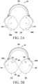
- FIGS. 2A and 2B are diagrams illustrating configuration examples of an electronic device according to an embodiment.
- the electronic device 201 may include a first sound output device 210 worn on a first location of the body (for example, left ear) and a second sound output device 220 worn on a second location of the body (for example, right ear).
- the electronic device 201 may include a connection member 203 for connecting the first sound output device 210 and the second sound output device 220.
- the configuration of the electronic device 201 is not limited thereto, and may be configured in various forms.
- the electronic device 201 may not include the connection member 203, and thus the first sound output device 210 and the second sound output device 220 may be separately configured and may be connected through a wireless communication scheme (for example, short-range wireless communication).
- each of the first sound output device 210 and the second sound output device 220 may include a plurality of microphones.
- the first sound output device 210 may include one or more external microphones 211 (for example three external microphones) among the plurality of microphones toward an outer surface 205a of the housing therein as illustrated in FIG. 2A .
- the second sound output device 220 may include one or more external microphones 221 (for example, three external microphones) among the plurality of microphones toward an outer lateral surface 205b of the housing therein.
- the processor 310 may be electrically or operatively connected to the power management circuit 320, the battery 321, the memory 330, the communication module 340, at least one microphone 350, the sensor module 360 including at least one sensor, the speaker 370, and/or the input circuit 380, and may perform the overall control operation of the electronic device 201.
- the processor 310 may include a voice-processing circuit, and may process audio data received from the second external electronic device 101 through the voice-processing circuit and perform control to output a sound signal (for example, an audio signal).
- the processor 310 may transmit the information for inducing re-wearing to the external electronic device through wireless communication to display the information through a display of the external electronic device (for example, the external electronic device 102 or 104 of FIG. 1 ) carried by the user.
- the processor 310 may output the information for inducing re-wearing in the form of a voice signal through the speakers 213 and 223 or in the form of a light through a light emitting device (for example, a light emitting diode) formed in a partial area of the housing (for example, an area that the user can check).
- a light emitting device for example, a light emitting diode
- the processor 310 may invert a sound signal for reception signals and control the first sound output device 210 to output the inverted sound signal through the speaker 213, and invert a sound signal for reception signals and control the second sound output device 210 to output the inverted sound signal through the speaker 223.
- the processor 310 may provide the information for inducing re-wearing and, after a specified time passes, identify whether the first sound output device 210 and the second sound output device 220 are put on again. When it is identified that the first sound output device 210 and the second sound output device 220 are not put on again, the processor 310 may invert the sound signal and control each of the first sound output device 210 and the second sound output device 220 to output the inverted sound signal.
- the processor 310 may control the first sound output device 210 to output the sound signal for reception signals through the speaker 213 and control the second sound output device 220 to output the sound signal (for example, a normal sound signal) for reception signals through the speaker 223.
- the processor 310 may control the battery 321 that provides power to operate the electronic device 201.
- the processor 310 may manage charging and discharging of the battery 321 through the power management circuit 320.
- the processor 310 may be configured to be included in each of the first sound output device 210 and the second sound output device 220 or may be formed in one of partial areas of the electronic device 201 (for example, a connection member, the first sound output device 210, or the second sound output device 220) to commonly control the first sound output device 210 and the second sound output device 220.
- the microphone module 320 may be included each of the first sound output device 210 and the second sound output device 220.
- the microphone module 320 of the first sound output device 210 may include at least one external mic 211 and the inner mic 212.
- the microphone module 320 of the second sound output device 220 may include at least one mic 221 and the inner mic 222.
- At least one inner mic (for example, inner mic) among the plurality of mics may be arranged at the location close to the inside of the ear, and one or more external mics may be arranged outside the ear while the electronic device 201 is worn on the user's ears.
- the microphone module 320 may be turned on (for example, activation or operation) or turned off (for example, deactivation or non-operation) by the control of the processor 310.
- the second mic 211b included in the first sound output device 210 may be arranged at the location closer to the user's ear (for example, the first location indicating the left ear) in the speaker direction from the lower area of the outer surface 205a based on the central location, and the second mic 221b included in the second sound output device 210 may be arranged at the location closer to the user's ear (for example, the second location indicating the right ear) in the speaker direction from the lower area of the outer surface 205b based on the central location.
- the multi-axis acceleration sensor may detect motion of the electronic device 201 (for example, movement direction) generated according to the user's motion to wear the electronic device 201. For example, when voice is spoken by the user, vibration of the user's vocal cords is detected by the multi-axis acceleration sensor and thus may be acquired as signals of at least some of a plurality of sounds related to voice signals.
- the technical idea of the disclosure may not be limited thereto, and may further include other sensors related to audio signal processing.
- FIGS. 6A and 6B illustrate examples for identifying normal wearing of the electronic device according to an embodiment.
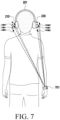
- the processor 310 of the electronic device 201 may control the communication module 340 to communicate with an external wearable device 701.
- the processor 310 may acquire information related to a wearing location (for example, the left wrist) of the external wearable device 701 through the communication module 340.
- the processor 310 may acquire, as a third reception signal, an inaudible frequency signal (for example, ultrasonic wave) generated from the external wearable device 701, based on the wearing location identified according to the information related to the wearing location through one or more external mics 211a, 211b, or 211c among the plurality of mics of the first sound output device 210 and one or more external mics 221a, 221b, or 221c among the plurality of mics of the second sound output device 220.
- an inaudible frequency signal for example, ultrasonic wave
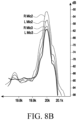
- the processor 310 may identify whether the first sound output device 210 and the second sound output device 220 are normally worn based on the wearing location and the acquired third reception signal. As illustrated in FIG. 8A , according to an embodiment, when the wearing location is the user's right wrist, the processor 310 may identify that the signal strength of the third reception signal of one or more mics (for example, a second mic (R Mic2) or a third mic (R MIc3)) of the second sound output device 220 worn on the right ear is greater than that of one or more mics (for example, a second mic (L Mic2) or a third mic (L Mic3)) of the first sound output device 210 worn on the left ear and the reception time (t) thereof is earlier during normal wearing, and may configure the signal strength and/or the reception time of the third reception signal received through one or more external mics 221a, 221b, or 221c of the second sound output device 220 as reference values during normal wearing.
- the signal strength of the third reception signal of one or more mics for example,
- the processor 310 may acquire the signal strength and/or the reception time of the third reception signal received through one or more mics 221a, 221b, or 221c of the second sound output device 220.
- the processor 310 may configure the signal strength and/or the reception time of the third reception signal received through one or more external mics 211a, 211b, or 211c of the first sound output device 210 as reference values.
- the processor 310 may identify that the first sound output device 210 and the second sound output device 220 are abnormally worn. According to an embodiment, when it is identified that the signal strength of the third reception signal is equal to or greater than the reference signal strength, the processor 310 may identify that the first sound output device 210 and the second sound output device 220 are normally worn.
- the processor 310 may identify that the first sound output device 210 and the second sound output device 220 are abnormally worn. According to an embodiment, when the signal strength of the third reception signal received by the second sound output device 220 is identified as a value equal to or less than the reference signal strength as opposed to the first sound output device 210, the processor 310 may identify that the first sound output device 210 and the second sound output device 220 are normally worn.
- the third reception signal received by each of one or more mics (for example, the second mic (L Mic2) or the third mic (L Mic3)) of the first sound output device 210 of the electronic device 201 and one or more mics (for example, the second mic (R Mic2) or the third mic (R Mic3)) of the second sound output device 220 may be indicated by frequency domain graphs (for example, L Mic2, L Mic3, R Mic2, and R Mic3) according to a time domain as illustrated in FIG. 8A . As shown in the graphs illustrated in FIG.
- the third reception signal of the first mic is not illustrated in the graphs of FIGS. 8A to 8C , the third reception signal of the first mic may be a signal having a signal level of an intermediate value and a reception time of an intermediate value of the third reception signal of the second mic and the reception signal of the third mic.
- the processor 310 may identify that the first sound output device 210 and the second sound output device 220 are abnormally worn. According to an embodiment, when it is identified that the reception time (for example, t2, t1, or t3 of L in FIG. 7 ) of the third reception signal is earlier than or equal to the reference reception time, the processor 310 may identify that the first sound output device 210 and the second sound output device 220 are normally worn.
- the processor 310 may identify that the first sound output device 210 and the second sound output device 220 are normally worn.
- the processor 310 may identify that the first sound output device 210 and the second sound output device 220 are normally worn.
- the processor 310 may identify that the first sound output device 210 and the second sound output device 220 are abnormally worn.
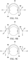
- the processor 310 may identify normal wearing or abnormal wearing based on a change in the movement direction of the x axis of each of the first acceleration sensor 901 and the second acceleration sensor 902.
- the processor 310 may identify that the first sound output device 210 and the second sound output device 220 are normally worn.
- the processor 310 may identify that the first sound output device 210 and the second sound output device 220 are abnormally worn.
- an electronic device may include a first sound output device (for example, the first sound output device 210 of FIGS. 2A, 2B , 3 , 4, 5 , 6A, 6B , 7 , and 9A to 9C ) including a plurality of mics (for example, the plurality of external mics 211 of FIG. 2A , the plurality of external mics 211a, 211b, and 211c of FIGS. 4 , 6A , 6B , and 7 , and the inner mic 212 of FIGS.
- a first sound output device for example, the first sound output device 210 of FIGS. 2A, 2B , 3 , 4, 5 , 6A, 6B , 7 , and 9A to 9C
- a plurality of mics for example, the plurality of external mics 211 of FIG. 2A , the plurality of external mics 211a, 211b, and 211c of FIGS. 4 , 6A , 6B , and 7 , and the
- the first sound output device may further include a first speaker (for example, the first speaker 213 of FIG. 2B ) and the second sound output device may further include a second speaker (for example, the first speaker 223 of FIG. 2B ).
- the at least one processor may be configured to identify the normal wearing of the first sound output device and the second sound output device, based on the signal level being less than a reference signal level and the reception time for the echo sound being earlier than a reference reception time.
- the at least one processor may be configured to identify the abnormal wearing of the first sound output device and the second sound output device, based on the signal level being greater than the reference signal level and the reception time for the echo sound being later than the reference reception time.
- the at least one processor may be configured to acquire a signal strength of each of a plurality of reception signals received from the plurality of microphones of the first sound output device or the plurality of microphones of the second sound output device, identify the normal wearing in case that it is identified that a size order of signal strengths of the plurality of reception signals corresponds to a specified size order, and identify the abnormal wearing in case that it is identified that the size order of the signal strengths of the plurality of reception signals is different from the specified size order.
- the at least one processor may be configured to acquire reception times of the reception signals received through the plurality of microphones of the first sound output device, identify the normal wearing in case that the reception time of each of the reception signals corresponds to a specified time order, and identify the abnormal wearing in case that the reception time of each of the reception signals is different from the specified time order.
- the first sound output device may further include a first acceleration sensor (for example, the first acceleration sensor 901 of FIGS. 9A to 9C ) and the second sound output device may further include a second acceleration sensor (for example, the second acceleration sensor 902 of FIGS. 9A to 9C ), and the first acceleration sensor and the second acceleration sensor may be arranged in opposite directions to each other.
- a first acceleration sensor for example, the first acceleration sensor 901 of FIGS. 9A to 9C
- the second sound output device may further include a second acceleration sensor (for example, the second acceleration sensor 902 of FIGS. 9A to 9C ), and the first acceleration sensor and the second acceleration sensor may be arranged in opposite directions to each other.
- the at least one processor may be configured to identify whether the first sound output device and the second sound output device are normally worn, based on a movement direction of each axis of the first acceleration sensor and the second acceleration sensor in case that the first sound output device and the second sound output device are worn.
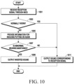
- FIG. 10 is a flowchart illustrating a method of operating the electronic device according to an embodiment of the disclosure.
- an electronic device (for example, the electronic device 101 of FIG. 1 and the electronic device 201 of FIGS. 2A, 2B , and 3 ) according to an embodiment may include a first sound output device (for example, the first sound output device 210 of FIGS. 2A, 2B , 3 , 4, 5 , 6A, 6B , 7 , and 9A to 9C ) and a second sound output device (for example, the second sound output device 220of FIGS.
- a first sound output device for example, the first sound output device 210 of FIGS. 2A, 2B , 3 , 4, 5 , 6A, 6B , 7 , and 9A to 9C
- a second sound output device for example, the second sound output device 220of FIGS.
- the first sound output device may be configured to be wearable on a first location of the body (for example, left (L) ear) and the second sound output device may be configured to be wearable on a second location of the body (for example, right (R) ear).
- components for example, at least one speaker and a plurality of mics
- components related to sound effects may be arranged to make the user feel a sense of space, based on a shape of the first location of the body and information indicating the first location of the body (for example, L indicating the left) may be imprinted in a partial area on the exterior of the housing.
- components related to sound effects may be arranged to make the user feel a sense of space, based on a shape of the second location of the body and information indicating the second location of the body (for example, R indicating the right) may be imprinted in a partial area on the exterior of the housing
- the electronic device may identify whether the first sound output device and the second sound output device are normally worn based on the reception signal. As a result, in the case of normal wearing, the electronic device may perform operation 1011, and in the case of abnormal wearing, the electronic device may perform operation 1005.
- the electronic device may output the information for inducing re-wearing in the form of a voice signal through a first speaker or a second speaker or in the form of a light through a light emitting device (for example, a light emitting diode) formed in a partial area of the housing (for example, an area that the user can check).
- a light emitting device for example, a light emitting diode
- the electronic device may identify whether abnormal wearing is maintained after a specified time passes. As a result, when the abnormal wearing is maintained, the electronic device may perform operation 1009, and when the abnormal wearing is not maintained, the electronic device may perform operation 1011.
- the electronic device may output the sound signal corresponding to reception signals through the speaker in response to the identification of normal wearing.
- the electronic device may identify normal wearing of the first sound output device and the second sound output device, based on at least one reception signal (for example, the first reception signal) received from at least one of the first inner mic (for example, the first inner mic 213 of FIG. 2B ) among the plurality of mics of the first sound output device or the second inner mic (for example, the second inner mic 222 of FIG. 2B ) among the plurality of mics of the second sound output device.
- the electronic device may acquire a signal level and a reception time of the first reception signal.
- the first reception signal may be an echo sound (for example, an echo signal) of a pilot signal output from the first speaker included in the first sound output device or the second speaker included in the second sound output device.
- the electronic device may configure a reference signal level and/or a reference time by identifying the reception level and/or the reception time of the echo sound in abnormal wearing, and the reception level and/or the reception time of the echo sound in normal wearing.
- the electronic device may identify that the user is normally wearing the first sound output device 210 and the second sound output device 220, based on the signal level of the first reception signal being less than the reference level or the time for the echo signal being earlier than the reference time.
- the processor 310 may identify that the user is abnormally wearing the first sound output device 210 and the second sound output device 220, based on the signal level of the first reception signal being greater than the reference level or the time for the echo sound being later than the reference time.
- the electronic device may identify normal wearing of the first sound output device and the second sound output device, based on one or more reception signals (for example, second reception signals) received from one or more external mics (for example, the external mics 211 of FIG. 2A ) among the plurality of mics of the first sound output device or one or more external mics (for example, the external mics 221 of FIG. 2A ) among the plurality of mics of the second sound output device.
- one or more reception signals for example, second reception signals
- the electronic device may compare the second reception signals and identify normal wearing or abnormal wearing, based on sizes of the signal strength (or size order) and/or reception time (or time order) of arrival at respective mics (for example, the mics 221a, 221b, and 221c of FIGS. 4 , 5A, and 5B).
- the electronic device may identify normal wearing.
- the electronic device may identify abnormal wearing.
- the normal wearing or the abnormal wearing may be identified based on the size order of the signal strength of the second reception signals received from the plurality of mics of the second sound output device.
- the electronic device may identify normal wearing.
- the processor 310 may identify abnormal wearing Although the operation for identifying normal wearing or abnormal wearing, based on the second reception signals received from the plurality of mics of the first sound output device has been described, the normal wearing or the abnormal wearing may be identified based on the size order of the signal strength of the second reception signals received from the plurality of mics of the second sound output device.
- the electronic device may identify normal wearing of the first sound output device and the second sound output device, based on inaudible frequencies (for example, the third reception signals) received from the external wearable device (for example, the external wearable device 701 of FIG. 7 ) through one or more external mics among the plurality of mics of the first sound output device and one or more external mics among the plurality of mics of the second sound output device and the wearing location of the external wearable device.
- the electronic device may compare the signal strength and/or the reception time of the third reception signal with the reference signal strength and/or the reference reception time.
- the electronic device may identify that the first sound output device 210 and the second sound output device 220 are abnormally worn. According to an embodiment, when it is identified that the signal strength of the third reception signal is equal to or greater than the reference signal strength, the electronic device may identify that the first sound output device 210 and the second sound output device 220 are normally worn. According to an embodiment, when the processor 310 identifies whether one of the first sound output device 210 or the second sound output device 220 is normally or abnormally worn, the other sound output device may not perform an operation of identifying normal wearing or abnormal wearing but may receive result information identified by the one sound output device and identify the normal wearing or the abnormal wearing.
- the electronic device may identify that the first sound output device and the second sound output device are abnormally worn. According to an embodiment, when it is identified that the reception time (t1-L, t2-L, or t3-L) of the third reception signal is equal to or earlier than the reference reception time, the electronic device may identify that the first sound output device and the second sound output device are normally worn.
Landscapes
- Engineering & Computer Science (AREA)
- Physics & Mathematics (AREA)
- Acoustics & Sound (AREA)
- Signal Processing (AREA)
- Health & Medical Sciences (AREA)
- General Health & Medical Sciences (AREA)
- Otolaryngology (AREA)
- Theoretical Computer Science (AREA)
- General Physics & Mathematics (AREA)
- Artificial Intelligence (AREA)
- Life Sciences & Earth Sciences (AREA)
- Bioinformatics & Cheminformatics (AREA)
- Bioinformatics & Computational Biology (AREA)
- Computer Vision & Pattern Recognition (AREA)
- Data Mining & Analysis (AREA)
- Evolutionary Biology (AREA)
- Evolutionary Computation (AREA)
- General Engineering & Computer Science (AREA)
- Manufacturing & Machinery (AREA)
- Circuit For Audible Band Transducer (AREA)
- Telephone Function (AREA)
Applications Claiming Priority (2)
| Application Number | Priority Date | Filing Date | Title |
|---|---|---|---|
| KR1020220118179A KR20240039520A (ko) | 2022-09-19 | 2022-09-19 | 음향 신호를 출력하기 위한 전자 장치 및 방법 |
| PCT/KR2023/013938 WO2024063456A1 (ko) | 2022-09-19 | 2023-09-15 | 음향 신호를 출력하기 위한 전자 장치, 방법 및 비 일시적 저장 매체 |
Publications (2)
| Publication Number | Publication Date |
|---|---|
| EP4583531A1 true EP4583531A1 (de) | 2025-07-09 |
| EP4583531A4 EP4583531A4 (de) | 2025-12-03 |
Family
ID=90454879
Family Applications (1)
| Application Number | Title | Priority Date | Filing Date |
|---|---|---|---|
| EP23868509.3A Pending EP4583531A4 (de) | 2022-09-19 | 2023-09-15 | Elektronische vorrichtung und verfahren zur ausgabe eines tonsignals und nichttransitorisches speichermedium |
Country Status (4)
| Country | Link |
|---|---|
| US (1) | US20250211908A1 (de) |
| EP (1) | EP4583531A4 (de) |
| KR (1) | KR20240039520A (de) |
| WO (1) | WO2024063456A1 (de) |
Family Cites Families (8)
| Publication number | Priority date | Publication date | Assignee | Title |
|---|---|---|---|---|
| US8401200B2 (en) * | 2009-11-19 | 2013-03-19 | Apple Inc. | Electronic device and headset with speaker seal evaluation capabilities |
| EP3529800B1 (de) * | 2016-10-24 | 2023-04-19 | Avnera Corporation | Erkennung von kopfhörern ausserhalb des ohrs |
| KR102535726B1 (ko) * | 2016-11-30 | 2023-05-24 | 삼성전자주식회사 | 이어폰 오장착 검출 방법, 이를 위한 전자 장치 및 저장 매체 |
| KR102673447B1 (ko) * | 2016-12-13 | 2024-06-11 | 삼성전자주식회사 | 전자 장치, 저장매체 및 전자 장치의 음성 신호 처리 방법 |
| US9894452B1 (en) * | 2017-02-24 | 2018-02-13 | Bose Corporation | Off-head detection of in-ear headset |
| US10462551B1 (en) * | 2018-12-06 | 2019-10-29 | Bose Corporation | Wearable audio device with head on/off state detection |
| KR102607566B1 (ko) * | 2019-04-01 | 2023-11-30 | 삼성전자주식회사 | 음향 장치의 착용 감지 방법 및 이를 지원하는 음향 장치 |
| KR102952330B1 (ko) * | 2020-08-04 | 2026-04-14 | 삼성전자주식회사 | 오디오 데이터를 처리하는 전자 장치와 이의 동작 방법 |
-
2022
- 2022-09-19 KR KR1020220118179A patent/KR20240039520A/ko active Pending
-
2023
- 2023-09-15 EP EP23868509.3A patent/EP4583531A4/de active Pending
- 2023-09-15 WO PCT/KR2023/013938 patent/WO2024063456A1/ko not_active Ceased
-
2025
- 2025-03-14 US US19/080,226 patent/US20250211908A1/en active Pending
Also Published As
| Publication number | Publication date |
|---|---|
| US20250211908A1 (en) | 2025-06-26 |
| KR20240039520A (ko) | 2024-03-26 |
| WO2024063456A1 (ko) | 2024-03-28 |
| EP4583531A4 (de) | 2025-12-03 |
Similar Documents
| Publication | Publication Date | Title |
|---|---|---|
| EP4236353A1 (de) | Elektronische vorrichtung mit öffnungs- und schliessstruktur | |
| KR20230106486A (ko) | 무선 이어폰 및 크래들을 포함하는 전자 장치 및 이의 동작 방법 | |
| US11849289B2 (en) | Electronic device for outputting sound and method for operating the same | |
| US12411653B2 (en) | Method and electronic device for detecting ambient audio signal | |
| EP4422207A1 (de) | Elektronische vorrichtung mit drahtlosem ohrhörer und träger sowie betriebsverfahren dafür | |
| US20230156394A1 (en) | Electronic device for sensing touch input and method therefor | |
| EP4391583A1 (de) | Wearable-vorrichtung | |
| EP4141612A1 (de) | Elektronische vorrichtung mit akustischer vertiefung | |
| US20240397248A1 (en) | Electronic device including sensor module | |
| US12101603B2 (en) | Electronic device including integrated inertia sensor and operating method thereof | |
| EP4258084A1 (de) | Elektronische vorrichtung zur reduzierung von internem rauschen und betriebsverfahren dafür | |
| EP4583531A1 (de) | Elektronische vorrichtung und verfahren zur ausgabe eines tonsignals und nichttransitorisches speichermedium | |
| US12294235B2 (en) | Electronic device for charging battery based on voltage of interface and method for controlling same | |
| EP4199535A1 (de) | Verfahren zum auffinden einer audioausgabevorrichtung unter verwendung einer stromversorgungsvorrichtung und stromversorgungsvorrichtung dafür | |
| US20250016501A1 (en) | External noise-based microphone and sensor control method and electronic device | |
| US12549882B2 (en) | Ear device and wearable electronic device including the same | |
| US20260012721A1 (en) | Wearable electronic device | |
| KR20220018854A (ko) | 관성 센서를 이용하여 전자 장치의 착용 상태를 감지하는 전자 장치 및 그 제어 방법 | |
| US12228644B2 (en) | Method for sensing wearing of electronic device and electronic device applied the same | |
| US20250357791A1 (en) | Electronic device for safely seating wireless audio device and fm radio signal outputting method using same | |
| US20250208655A1 (en) | Electronic apparatus comprising frame detachably coupled to housing | |
| EP4738646A1 (de) | Elektronische vorrichtung zum laden einer wearable-vorrichtung | |
| US20250244796A1 (en) | Wearable electronic device comprising conductive pin | |
| US20260056573A1 (en) | Speaker module and electronic device comprising speaker module | |
| EP4432701A1 (de) | Elektronische vorrichtung und verfahren zur steuerung davon |
Legal Events
| Date | Code | Title | Description |
|---|---|---|---|
| STAA | Information on the status of an ep patent application or granted ep patent |
Free format text: STATUS: THE INTERNATIONAL PUBLICATION HAS BEEN MADE |
|
| PUAI | Public reference made under article 153(3) epc to a published international application that has entered the european phase |
Free format text: ORIGINAL CODE: 0009012 |
|
| STAA | Information on the status of an ep patent application or granted ep patent |
Free format text: STATUS: REQUEST FOR EXAMINATION WAS MADE |
|
| 17P | Request for examination filed |
Effective date: 20250403 |
|
| AK | Designated contracting states |
Kind code of ref document: A1 Designated state(s): AL AT BE BG CH CY CZ DE DK EE ES FI FR GB GR HR HU IE IS IT LI LT LU LV MC ME MK MT NL NO PL PT RO RS SE SI SK SM TR |
|
| A4 | Supplementary search report drawn up and despatched |
Effective date: 20251103 |
|
| RIC1 | Information provided on ipc code assigned before grant |
Ipc: H04R 1/10 20060101AFI20251028BHEP Ipc: H04R 3/02 20060101ALI20251028BHEP Ipc: H04R 3/00 20060101ALI20251028BHEP Ipc: H04R 29/00 20060101ALI20251028BHEP Ipc: H04R 5/033 20060101ALI20251028BHEP Ipc: G06F 18/00 20230101ALI20251028BHEP Ipc: G01P 15/00 20060101ALI20251028BHEP |
|
| DAV | Request for validation of the european patent (deleted) | ||
| DAX | Request for extension of the european patent (deleted) |