EP4583478A2 - Ppdu-übertragungsverfahren und zugehörige vorrichtung - Google Patents
Ppdu-übertragungsverfahren und zugehörige vorrichtung Download PDFInfo
- Publication number
- EP4583478A2 EP4583478A2 EP25154006.8A EP25154006A EP4583478A2 EP 4583478 A2 EP4583478 A2 EP 4583478A2 EP 25154006 A EP25154006 A EP 25154006A EP 4583478 A2 EP4583478 A2 EP 4583478A2
- Authority
- EP
- European Patent Office
- Prior art keywords
- tone
- mhz
- mru
- resource unit
- unit allocation
- Prior art date
- Legal status (The legal status is an assumption and is not a legal conclusion. Google has not performed a legal analysis and makes no representation as to the accuracy of the status listed.)
- Pending
Links
Images


Classifications
-
- H—ELECTRICITY
- H04—ELECTRIC COMMUNICATION TECHNIQUE
- H04W—WIRELESS COMMUNICATION NETWORKS
- H04W72/00—Local resource management
- H04W72/04—Wireless resource allocation
- H04W72/044—Wireless resource allocation based on the type of the allocated resource
- H04W72/0453—Resources in frequency domain, e.g. a carrier in FDMA
-
- H—ELECTRICITY
- H04—ELECTRIC COMMUNICATION TECHNIQUE
- H04L—TRANSMISSION OF DIGITAL INFORMATION, e.g. TELEGRAPHIC COMMUNICATION
- H04L1/00—Arrangements for detecting or preventing errors in the information received
- H04L1/12—Arrangements for detecting or preventing errors in the information received by using return channel
- H04L1/16—Arrangements for detecting or preventing errors in the information received by using return channel in which the return channel carries supervisory signals, e.g. repetition request signals
- H04L1/1607—Details of the supervisory signal
- H04L1/1642—Formats specially adapted for sequence numbers
-
- H—ELECTRICITY
- H04—ELECTRIC COMMUNICATION TECHNIQUE
- H04L—TRANSMISSION OF DIGITAL INFORMATION, e.g. TELEGRAPHIC COMMUNICATION
- H04L27/00—Modulated-carrier systems
- H04L27/26—Systems using multi-frequency codes
- H04L27/2601—Multicarrier modulation systems
- H04L27/2602—Signal structure
-
- H—ELECTRICITY
- H04—ELECTRIC COMMUNICATION TECHNIQUE
- H04L—TRANSMISSION OF DIGITAL INFORMATION, e.g. TELEGRAPHIC COMMUNICATION
- H04L5/00—Arrangements affording multiple use of the transmission path
- H04L5/003—Arrangements for allocating sub-channels of the transmission path
- H04L5/0044—Allocation of payload; Allocation of data channels, e.g. PDSCH or PUSCH
-
- H—ELECTRICITY
- H04—ELECTRIC COMMUNICATION TECHNIQUE
- H04L—TRANSMISSION OF DIGITAL INFORMATION, e.g. TELEGRAPHIC COMMUNICATION
- H04L5/00—Arrangements affording multiple use of the transmission path
- H04L5/003—Arrangements for allocating sub-channels of the transmission path
- H04L5/0058—Allocation criteria
-
- H—ELECTRICITY
- H04—ELECTRIC COMMUNICATION TECHNIQUE
- H04L—TRANSMISSION OF DIGITAL INFORMATION, e.g. TELEGRAPHIC COMMUNICATION
- H04L5/00—Arrangements affording multiple use of the transmission path
- H04L5/0091—Signalling for the administration of the divided path, e.g. signalling of configuration information
- H04L5/0094—Indication of how sub-channels of the path are allocated
-
- H—ELECTRICITY
- H04—ELECTRIC COMMUNICATION TECHNIQUE
- H04W—WIRELESS COMMUNICATION NETWORKS
- H04W72/00—Local resource management
- H04W72/04—Wireless resource allocation
- H04W72/044—Wireless resource allocation based on the type of the allocated resource
- H04W72/0446—Resources in time domain, e.g. slots or frames
-
- H—ELECTRICITY
- H04—ELECTRIC COMMUNICATION TECHNIQUE
- H04W—WIRELESS COMMUNICATION NETWORKS
- H04W72/00—Local resource management
- H04W72/04—Wireless resource allocation
- H04W72/044—Wireless resource allocation based on the type of the allocated resource
- H04W72/0457—Variable allocation of band or rate
-
- H—ELECTRICITY
- H04—ELECTRIC COMMUNICATION TECHNIQUE
- H04W—WIRELESS COMMUNICATION NETWORKS
- H04W88/00—Devices specially adapted for wireless communication networks, e.g. terminals, base stations or access point devices
- H04W88/02—Terminal devices
- H04W88/06—Terminal devices adapted for operation in multiple networks or having at least two operational modes, e.g. multi-mode terminals
-
- H—ELECTRICITY
- H04—ELECTRIC COMMUNICATION TECHNIQUE
- H04B—TRANSMISSION
- H04B7/00—Radio transmission systems, i.e. using radiation field
- H04B7/02—Diversity systems; Multi-antenna system, i.e. transmission or reception using multiple antennas
- H04B7/04—Diversity systems; Multi-antenna system, i.e. transmission or reception using multiple antennas using two or more spaced independent antennas
- H04B7/06—Diversity systems; Multi-antenna system, i.e. transmission or reception using multiple antennas using two or more spaced independent antennas at the transmitting station
- H04B7/0613—Diversity systems; Multi-antenna system, i.e. transmission or reception using multiple antennas using two or more spaced independent antennas at the transmitting station using simultaneous transmission
- H04B7/0615—Diversity systems; Multi-antenna system, i.e. transmission or reception using multiple antennas using two or more spaced independent antennas at the transmitting station using simultaneous transmission of weighted versions of same signal
- H04B7/0619—Diversity systems; Multi-antenna system, i.e. transmission or reception using multiple antennas using two or more spaced independent antennas at the transmitting station using simultaneous transmission of weighted versions of same signal using feedback from receiving side
- H04B7/0621—Feedback content
- H04B7/0626—Channel coefficients, e.g. channel state information [CSI]
-
- H—ELECTRICITY
- H04—ELECTRIC COMMUNICATION TECHNIQUE
- H04L—TRANSMISSION OF DIGITAL INFORMATION, e.g. TELEGRAPHIC COMMUNICATION
- H04L5/00—Arrangements affording multiple use of the transmission path
- H04L5/0001—Arrangements for dividing the transmission path
- H04L5/0003—Two-dimensional division
- H04L5/0005—Time-frequency
- H04L5/0007—Time-frequency the frequencies being orthogonal, e.g. OFDM(A) or DMT
-
- H—ELECTRICITY
- H04—ELECTRIC COMMUNICATION TECHNIQUE
- H04L—TRANSMISSION OF DIGITAL INFORMATION, e.g. TELEGRAPHIC COMMUNICATION
- H04L5/00—Arrangements affording multiple use of the transmission path
- H04L5/003—Arrangements for allocating sub-channels of the transmission path
- H04L5/0058—Allocation criteria
- H04L5/0064—Rate requirement of the data, e.g. scalable bandwidth, data priority
-
- H—ELECTRICITY
- H04—ELECTRIC COMMUNICATION TECHNIQUE
- H04W—WIRELESS COMMUNICATION NETWORKS
- H04W84/00—Network topologies
- H04W84/02—Hierarchically pre-organised networks, e.g. paging networks, cellular networks, WLAN [Wireless Local Area Network] or WLL [Wireless Local Loop]
- H04W84/10—Small scale networks; Flat hierarchical networks
- H04W84/12—WLAN [Wireless Local Area Networks]
Definitions
- the communication standard specifies the frequency locations, in the 240 MHz bandwidth, of the 996-tone RU and the 484-tone RU that form each first MRU.
- the communication apparatus can determine, based on the resource unit allocation subfield, that the bandwidth for transmitting the PPDU includes two first MRUs, and can accurately determine the frequency locations, in the 240 MHz bandwidth, of the 996-tone RU and the 484-tone RU that form each first MRU, thereby allocating an MRU obtained by combining a 996-tone RU and a 484-tone RU to one or more users.
- this application further provides a PPDU communication apparatus, including:
- the communication apparatus can determine, based on the resource unit allocation subfields, that the bandwidth for transmitting the PPDU includes the first MRU and the second MRU, and can accurately determine the frequency locations, in the 320 MHz bandwidth, of the 996-tone RU and the 484-tone RU that form the first RU and the 2*996-tone RU and the 484-tone RU that form the second MRU, thereby allocating an MRU obtained by combining a 2*996-tone RU and a 484-tone RU to one or more users.
- this application further provides a PPDU communication apparatus, including:
- the processing unit of the communication apparatus can determine, based on the resource unit allocation subfield corresponding to the lowest 80 MHz frequency and the resource unit allocation field corresponding to the highest 80 MHz frequency, the frequency locations, in the 240 MHz bandwidth, of the 996-tone RU and the 484-tone RU that form the first MRU, that is, determine RUs at which frequency locations in the 240 MHz bandwidth the RUs that form the first MRU are.
- this application further provides a PPDU communication apparatus, including:
- the communication apparatus can determine, based on the resource unit allocation subfield corresponding to the second lowest 80 MHz frequency and a resource unit allocation field corresponding to the highest 80 MHz frequency, the frequency locations, in the 240 MHz bandwidth, of the 996-tone RU and the 484-tone RU that form the first MRU, that is, determine RUs at which frequency locations in the 240 MHz bandwidth the RUs that form the first MRU are.
- this solution may be applied to a scenario in which the 240 MHz bandwidth includes one first MRU, or may be applied to a scenario in which the 240 MHz bandwidth includes two first MRUs.
- the communication apparatus when determining frequency locations of a 996-tone RU and a 484-tone RU that form a 996+484-tone RU or a 484+996-tone RU, can accurately determine, based on the resource unit allocation subfield corresponding to the second lowest 80 MHz frequency and/or a resource unit allocation subfield corresponding to the highest 80 MHz frequency, frequency locations, in the 240 MHz bandwidth, of the 996-tone RU and the 484-tone RU that form the 996+484-tone RU or the 484+996-tone RU, thereby allocating an MRU obtained by combining a 996-tone RU and a 484-tone RU to one or more users.
- the communication apparatuses in the thirteenth aspect to the eighteenth aspect are PPDU sending apparatuses
- the communication apparatuses in the nineteenth aspect to the twenty-fourth aspect are PPDU receiving apparatuses.
- the PPDU transmitting end may be an access point, or may be a station.
- the PPDU receiving end may be an access point, or may be a station.
- an implementation of this application further provides a communication apparatus, configured to transmit a PPDU.
- the communication apparatus may include a processor, a transceiver, and optionally further include a memory.
- the processor executes a computer program or instructions in the memory, the method according to any one of the implementations of the first aspect to the twelfth aspect is performed.
- an implementation of this application further provides a computer-readable storage medium.
- the computer-readable storage medium stores instructions, and the instructions indicate a communication apparatus to perform the method according to any one of the implementations of the first aspect to the twelfth aspect.
- an implementation of this application further provides a computer program product.
- the computer program product includes a computer program.
- the computer program When the computer program is run on a computer, the computer is enabled to perform the method according to any one of the implementations of the first aspect to the twelfth aspect.
- this application further provides a processor, configured to perform the method according to any one of the implementations of the first aspect to the twelfth aspect.
- a process of sending the foregoing information and a process of receiving the foregoing information in the foregoing methods may be understood as a process of outputting the foregoing information by the processor and a process of receiving the foregoing input information by the processor.
- the processor when outputting the information, the processor outputs the information to a transceiver, so that the transceiver transmits the information.
- the transceiver receives the information and inputs the information into the processor.
- the transceiver receives the information, other processing may need to be performed on the information before the information is input into the processor.
- the operations may be more generally understood as operations such as input, receiving, and output of the processor, instead of operations such as transmission, sending, and receiving directly performed by a radio frequency circuit and an antenna.
- the processor may be a processor specially configured to perform these methods, or a processor, for example, a general purpose processor, configured to execute a computer instruction in a memory to perform these methods.
- the memory may be a non-transitory memory such as a read-only memory (read only memory, ROM).
- ROM read only memory
- the memory and the processor may be integrated on a same chip, or may be separately disposed on different chips. A type of the memory and a manner of disposing the memory and the processor are not limited in the embodiments of the present invention.
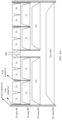
- this application provides a chip system.
- the chip system includes a processor and an interface, configured to support a communication transmission device in implementing a function in the method according to any one of the first aspect to the eighth aspect, for example, determining or processing at least one of data and information involved in the foregoing method.
- the chip system further includes a memory, and the memory is configured to store information and data that are necessary for the foregoing communication apparatus.
- the chip system may include a chip, or may include the chip and another discrete component.
- this application provides a functional entity.
- the functional entity is configured to implement the method according to any one of the first aspect to the eighth aspect.
- Embodiments of this application may be applied to a wireless local area network (wireless local area network, WLAN) scenario, and may be applied to an IEEE 802.11 system standard, for example, the IEEE 802.11be standard, or a next-generation standard or a further next-generation standard.
- embodiments of this application may be applied to a wireless local area network system, for example, an internet of things (internet of things, IoT) or a vehicle-to-everything (Vehicle to X, V2X) network.
- IoT internet of things
- Vehicle to X vehicle-to-everything
- embodiments of this application may be further applied to other possible communication systems, for example, a global system for mobile communications (global system for mobile communications, GSM), a code division multiple access (code division multiple access, CDMA) system, a wideband code division multiple access (wideband code division multiple access, WCDMA) system, a general packet radio service (general packet radio service, GPRS), a long term evolution (long term evolution, LTE) system, an LTE frequency division duplex (frequency division duplex, FDD) system, an LTE time division duplex (time division duplex, TDD) system, a universal mobile telecommunication system (universal mobile telecommunication system, UMTS), a worldwide interoperability for microwave access (worldwide interoperability for microwave access, WiMAX) communication system, and a future 5G communication system.
- GSM global system for mobile communications
- CDMA code division multiple access
- WCDMA wideband code division multiple access
- GPRS general packet radio service
- LTE long term evolution
- LTE long term evolution
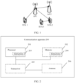
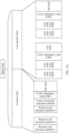
- FIG. 1 shows a network structure to which the PPDU transmission method in this application is applicable.
- FIG. 1 is a schematic diagram of a network structure according to an embodiment of this application.
- the network structure may include one or more access point (access point, AP) stations and one or more non-access point stations (non access point stations, non-AP STAs).
- access point access point
- AP access point
- STA station
- the APs are, for example, AP1 and AP2 in FIG. 1
- the STAs are, for example, STA1, STA2, and STA3 in FIG. 1 .
- the station may include a processor and a transceiver.
- the processor is configured to control and manage an action of the access point, and the transceiver is configured to receive or send information.
- the access point in this application may be a high efficient (high efficiency, HE) STA or an extremely high throughput (extremely high throughput, EHT) STA, or may be a STA applicable to a future Wi-Fi standard.
- HE high efficiency
- EHT extremely high throughput
- the access point and the station may be devices applied to the internet of vehicles, internet of things nodes or sensors on the internet of things (IoT, internet of things), smart cameras, smart remote controls, and smart water meters in a smart home, and sensors in a smart city.
- IoT internet of things
- smart cameras smart cameras
- smart remote controls smart water meters in a smart home
- sensors in a smart city sensors in a smart city.
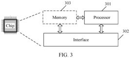
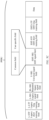
- FIG. 2 is a schematic diagram of a structure of a communication apparatus according to an embodiment of this application.
- the communication apparatus 200 may include a processor 201 and a transceiver 205, and optionally further include a memory 202.
- the memory 202 may store a computer program, software code, or instructions 204, where the computer program, the software code, or the instructions 204 may further be referred to as firmware.
- the processor 201 may control a MAC layer and a PHY layer by running a computer program, software code, or instructions 203 in the processor 201, or by invoking the computer program, the software code, or the instructions 204 stored in the memory 202, to implement a PPDU transmission method provided in the following embodiments of this application.
- the processor 201 may be a central processing unit (central processing unit, CPU), and the memory 202 may be, for example, a read-only memory (read-only memory, ROM), or a random access memory (random access memory, RAM).
- the processor 201 and the transceiver 205 described in this application may be implemented in an integrated circuit (integrated circuit, IC), an analog IC, a radio frequency integrated circuit RFIC, a mixed-signal IC, an application-specific integrated circuit (application-specific integrated circuit, ASIC), a printed circuit board (printed circuit board, PCB), an electronic device, or the like.
- integrated circuit integrated circuit, IC
- analog IC analog IC
- radio frequency integrated circuit RFIC radio frequency integrated circuit
- RFIC radio frequency integrated circuit
- mixed-signal IC mixed-signal IC
- ASIC application-specific integrated circuit
- PCB printed circuit board
- an electronic device or the like.
- the communication apparatus 200 may further include an antenna 206.
- the modules included in the communication apparatus 200 are merely examples for description, and are not limited in this application.
- Embodiments of this application do not limit the protection scope and applicability of the claims.
- a person skilled in the art may adaptively change functions and deployments of elements in this application, or omit, replace, or add various processes or components as appropriate without departing from the scope of the embodiments of this application.
- a difference between 160 MHz and 80+80 MHz lies in that the former is a consecutive frequency band, and two 80 MHz subblocks of the latter may be separated, that is, a 160 MHz subblock formed by 80+80 MHz is non-consecutive.
- FIG. 4A is a schematic diagram of a possible resource unit allocation manner used when the bandwidth for transmitting the PPDU is 20 MHz.
- the entire 20 MHz bandwidth may include an entire resource unit (242-tone RU) that includes 242 subcarriers, or may include various combinations of resource units (26-tone RUs) including 26 subcarriers, resource units (52-tone RUs) including 52 subcarriers, or resource units (106-tone RUs) including 106 subcarriers.
- some guard (Guard) subcarriers, null subcarriers, or direct current (Direct Current, DC) subcarriers are further included.
- the entire channel bandwidth is approximately equivalent to two replications of a tone plan of 40 MHz.
- the entire 80 MHz bandwidth may include an entire resource unit (996-tone RU) that includes 996 subcarriers, or may include various combinations of 484-tone RUs, 242-tone RUs, 106-tone RUs, 52-tone RUs, or 26-tone RUs.
- a center 26-tone RU Center 26-Tone RU
- Center 26-Tone RU including two 13-tone subunits exists in the middle of the entire 80 MHz channel bandwidth.
- the AP allocates a resource to the STA by RU, and may notify, by using a physical layer protocol data unit (physical layer protocol data unit, PPDU), the STA of the resource allocated to the STA.
- the AP may include resource allocation information in a signal field (Signal Field, SIG) included in the PPDU, to indicate an allocated RU to the STA.
- SIG Signal Field
- the signal field may be a high efficiency signal field B (High Efficient Signal Field-B, HE-SIG-B), or may be an extremely high-throughput signal field (Extremely High Throughput Signal Field, EHT-SIG).
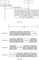
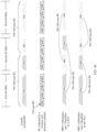
- FIG. 5A is a schematic diagram of a structure of a signal field. As shown in FIG. 5A , HE-SIG includes a common field (common field) and a user specific field (user specific field).
- the common field includes 1 to N resource unit allocation subfields (RU allocation subfields), a cyclic redundancy code (cyclic redundancy code, CRC) used for checking, and a tail (Tail) subfield used for cyclic decoding.
- the user specific field includes a user field corresponding to an RU indicated by the resource unit allocation subfield.
- One resource unit allocation subfield is one resource unit allocation index, and one resource unit allocation index indicates a size and a location of one or more resource units corresponding to one 242-tone RU. It should be understood that one resource unit allocation subfield corresponds to one 242-tone RU, and one 20 MHz subblock corresponds to one 242-tone RU. In this case, it may also be understood as that one resource unit allocation subfield corresponds to one 20 MHz subblock.
- the resource unit allocation subfield may be an index in the first column in Table 1, and indicates a resource unit allocation status corresponding to 20 MHz corresponding to the resource unit allocation subfield.
- the resource unit allocation subfield is "00111y 2 y 1 y 0 ", indicating that a 242-tone RU corresponding to the resource unit allocation subfield is divided into four RUs: a 52-tone RU, a 52-tone RU, a 26-tone RU, and a 106-tone RU.
- the resource unit allocation subfields corresponding to the eleventh to the sixteenth 242-tone RUs in the 320 MHz bandwidth may use the indices 1 to 9 in Table 9 to indicate that the corresponding 242-tone RU belongs to a 996+484-tone RU.
- the STA receiving the PPDU may determine, based on the resource unit allocation subfields 1 to 16 in the signal field, that the first to the tenth 242-tone RUs in the 320 MHz bandwidth belong to one 2*996+484-tone RU and that the eleventh to the sixteenth 242-tone RUs belong to one 996+484-tone RU. It can be learned that such a solution can accurately indicate a case in which when the bandwidth for transmitting the PPDU is 320 MHz, the first to the tenth 242-tone RUs belong to one 2*996+484-tone RU, and the eleventh to the sixteenth 242-tone RUs belong to one 996+484-tone RU.
- such a solution can accurately indicate that when the bandwidth, of 320 MHz, for transmitting the PPDU includes the 2*996-tone RU and the 996+484-tone RU, the resource unit allocation subfield can accurately indicate, by the indices in Table 9, the 2*996-tone RU and the 484-tone RU that form the 2*996+484-tone RU and the 996-tone RU and the 484-tone RU that form the 996+484-tone RU.
- a STA to which the 2*996+484-tone RU is allocated can determine, based on the resource unit allocation subfield, a specific 2*996-tone RU and a specific 484-tone RU that form the 2*996+484-tone RU allocated to the STA.
- the first to the sixth 242-tone RUs belong to one 484+996-tone RU
- the seventh to twelfth 242-tone RUs belong to one 996+484-tone RU.
- the first to the fourth 242-tone RUs may be understood as the first to the fourth 242-tone RUs in the first 80 MHz subblock
- the fifth to the eighth 20 MHz subblocks may be understood as the first to the fourth 242-tone RUs in the second 80 MHz subblock
- the ninth to the twelfth 20 MHz subblocks may be understood as the first to the fourth 242-tone RUs in the third 80 MHz subblock.
- the signal field of the PPDU includes a resource unit allocation subfield 1 to a resource unit allocation subfield 12 that respectively correspond to the first to the twelfth 242-tone RUs in the 240 MHz bandwidth, and the resource unit allocation subfield 1 to the resource unit allocation subfield 12 may be indicated by an index in Table 8.
- the STA receiving the PPDU may determine, based on the resource unit allocation subfields 1 to 12 in the signal field, that the first to the twelfth 242-tone RUs in the 240 MHz bandwidth belong to the 996+484-tone RU. It can be learned from the foregoing description corresponding to FIG.
- each 996+484-tone RU includes a 242-tone RU is not single.
- the first to fourth 242-tone RUs and the seventh and the eighth 242-tone RUs may belong to one 996+484-tone RU
- the fifth and the sixth 242-tone RUs and the ninth to the twelfth 242-tone RUs may belong to one 996+484-tone RU.
- the first to the sixth 242-tone RUs belong to one 996+484-tone RU
- the seventh to the twelfth 242-tone RUs belong to one 996+484-tone RU.
- the resource unit allocation subfield when the 240 MHz bandwidth includes two (996+484)-tone RUs, the resource unit allocation subfield cannot indicate, by the index in Table 9, a 996-tone RU and a 484-tone RU that form each 996+484-tone RU.
- the STA receiving the PPDU cannot determine a specific 996-tone RU and a specific 484-tone RU that form a 996+484-tone RU in the 240 MHz bandwidth, and therefore, one 996+484-tone RU or two (996+484)-tone RUs cannot be allocated to one or more stations.
- Embodiments of this application provide some solutions that can resolve a problem that a resource unit allocation subfield cannot accurately indicate a 2*996+484-tone RU and a 996+484-tone RU included in the 320 MHz bandwidth.
- the 2*996+484-tone RU is an MRU including a 2*996-tone RU of a lower frequency and a 484-tone RU of a higher frequency, and an MRU including a 484-tone RU of a lower frequency and a 2*996-tone RU of a higher frequency.
- the 996+484-tone RU is an MRU including a 996-tone RU of a lower frequency and a 484-tone RU of a higher frequency, and an MRU including a 484-tone RU of a lower frequency and a 996-tone RU of a higher frequency.
- a 2*996+484-tone RU and a 996+484-tone RU are not allowed to be included in a consecutive 320 MHz bandwidth.
- the resource unit allocation subfield does not need to indicate the 2*996+484-tone RU and the 996+484-tone RU in the 320 MHz bandwidth. This can resolve a problem that accurate indication cannot be performed.
- FIG. 7A is a schematic scenario diagram of MRU combination cases included in 240 MHz.
- the 320 MHz bandwidth includes a 2*996+484-tone RU and a 996+484-tone RU
- the 320 MHz bandwidth includes a 2*996-tone RU, a 484-tone RU, a 484-tone RU, and a 996-tone RU in an increasing absolute-frequency order.
- the STA receiving the PPDU only needs to identify, based on the resource unit allocation subfield, that the 320 MHz bandwidth includes the 2*996+484-tone RU and the 996+484-tone RU, to determine the 2*996-tone RU and the 484-tone RU that form the 2*996-tone+484 RU and the 996-tone RU and the 484-tone RU that form the 996+484-tone RU.
- the STA can identify, based on the resource unit allocation subfield, that the 320 MHz bandwidth includes the 2*996+484-tone RU and the 996+484-tone RU, to determine the 2*996-tone RU and the 484-tone RU that form the 2*996-tone+484 RU and the 996-tone RU and the 484-tone RU that form the 996+484-tone RU.
- This embodiment of this application further provides some indication solutions for indicating a frequency location of a single RU in an MRU.
- the bandwidth, of 240 MHz, for transmitting the PPDU includes an MRU including a 484-tone RU and a 996-tone RU
- the STA receiving the PPDU can accurately determine a specific 484-tone RU and a specific 996-tone RU that form the MRU.
- a 242-tone RU and a 484-tone RU in an 80 MHz subblock may also be numbered.
- two 484-tone RUs in an 80 MHz subblock are sequentially the first 484-tone RU (1 st 484-tone RU) and the second 484-tone RU (2 nd 484-tone RU) in an increasing absolute-frequency order.
- RU numbers of the first 484-tone RU and the second 484-tone RU in the 80 MHz subblock are sequentially 1 and 2.
- a resource unit allocation subfield indicating the MRU including the 484-tone RU and the 996-tone RU indicates the RU numbers of the 484-tone RU and the 996-tone RU that form the MRU in the 160 MHz bandwidth in which the MRU is located, to indicate frequency locations of the 484-tone RU and the 996-tone RU that form the MRU in the 160 MHz subblock to which the 996+484-tone RU belongs.
- an embodiment of this application further provides a solution for determining, based on the signal field, frequency locations of a 484-tone RU and a 996-tone RU forming an MRU.
- the STA receiving the PPDU skips a resource unit allocation indication subfield corresponding to the second 80 MHz subblock in the 240 MHz bandwidth.
- the STA determines the frequency locations of the 484-tone RU and the 996-tone RU that form the MRU in the 160 MHz subblock to which the MRU belongs, based on the RU numbers, of the 484-tone RU and the 996-tone RU that form the MRU in the 160 MHz subblock to which the MRU belongs, indicated by the resource unit allocation indication subfield corresponding to the first 80 MHz subblock and/or the third 80 MHz subblock in the 240 MHz bandwidth.
- the STA determines, depending on whether the resource unit allocation subfield indicating the MRU is a resource unit allocation subfield corresponding to the first 80 MHz subblock or a resource unit allocation subfield corresponding to the third 80 MHz subblock, whether the 160 MHz subblock to which the MRU belongs is the lowest 160 MHz frequency or the highest 160 MHz frequency in the 240 MHz bandwidth, to determine a specific 484-tone RU and a specific 996-tone RU that form the MRU.
- an embodiment in which an AP sends a PPDU to a STA is used for description.
- the method in this application is also applicable to a scenario in which an AP sends a PPDU to an AP and a scenario in which a STA sends a PPDU to a STA.
- a 996+484-tone RU in this embodiment is an MRU including a 996-tone RU with a low frequency and a 484-tone RU with a high frequency.
- a 484+996-tone RU in the embodiment of the PPDU transmission method in this application is an MRU including a 484-tone RU with a low frequency and a 996-tone RU with a high frequency.
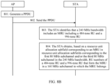
- FIG. 8B is a schematic flowchart of a PPDU transmission method.
- the PPDU transmission method includes the following steps.
- An AP generates a PPDU.
- a bandwidth for transmitting the PPDU includes consecutive 240 MHz.
- the 240 MHz bandwidth includes an MRU including a 996-tone RU and a 484-tone RU, and the MRU is a 996+484-tone RU or a 484+996-tone RU.
- each MRU in this embodiment may be understood as a 996+484-tone RU or a 484+996-tone RU.
- the bandwidth for transmitting the PPDU is consecutive 240 MHz.
- the PPDU includes a plurality of resource unit allocation subfields corresponding to the 240 MHz bandwidth, and includes at least one resource unit allocation subfield corresponding to the MRU.
- the resource unit allocation subfield corresponding to the MRU indicates RU numbers of the 484-tone RU and the 996-tone RU forming the MRU in a 160 MHz subblock to which the MRU belongs.
- the resource unit allocation subfield corresponding to the MRU in a resource unit allocation subfield corresponding to the first 80 MHz subblock and/or a resource unit allocation subfield corresponding to the third 80 MHz subblock in the 240 MHz bandwidth is for determining or indicating frequency locations of the 484-tone RU and the 996-tone RU that form the MRU in the 240 MHz bandwidth.
- the PPDU includes a signal field
- the signal field includes a common field and a user specific field.
- the common field includes the plurality of resource unit allocation subfields corresponding to the 240 MHz bandwidth.
- the user specific field includes a user field.
- the resource unit allocation subfield corresponding to the MRU further indicates a user field corresponding to the MRU, or the resource unit allocation subfield corresponding to the MRU further indicates a number of user fields contributed to a user specific field in a same EHT-SIG content channel as the resource unit allocation subfield.
- a structure of the PPDU may be but is not limited to the structure shown in FIG. 5C .
- the signal field may be, for example, but is not limited to, the EHT-SIG in the PPDU shown in FIG. 5C .
- the AP sends the PPDU.
- a STA receives the PPDU.
- the STA identifies, based on the resource unit allocation subfield, that the 240 MHz bandwidth includes the MRU including the 484-tone RU and the 996-tone RU.
- the STA may identify, based on the plurality of resource unit allocation subfields corresponding to the 240 MHz bandwidth in the signal field, that the 240 MHz bandwidth includes the MRU including the 484-tone RU and the 996-tone RU.
- the solution in this embodiment of this application is applicable to a scenario in which the lowest 160 MHz frequency in the 240 MHz bandwidth includes one MRU including a 996-tone RU and a 484-tone RU, applicable to a scenario in which the highest 160 MHz frequency in the 240 MHz bandwidth includes one MRU including a 996-tone RU and a 484-tone RU, and applicable to a scenario in which the 240 MHz bandwidth includes two MRUs and each MRU includes a 996-tone RU and a 484-tone RU.
- the 484-tone RU and the 996-tone RU that form one of the MRUs are at the lowest 160 MHz frequency in the 240 MHz bandwidth, and the 484-tone RU and the 996-tone RU that form the other MRU are at the highest 160 MHz frequency in the 240 MHz bandwidth.
- the MRU including the 484-tone RU and the 996-tone RU in the lowest 160 MHz frequency in the 240 MHz bandwidth is referred to as a low-frequency MRU
- the MRU including the 484-tone RU and the 996-tone RU in the highest 160 MHz frequency in the 240 MHz bandwidth is referred to as a high-frequency MRU.
- the 240 MHz bandwidth includes a low-frequency MRU.
- the STA may identify, based on a resource unit allocation subfield corresponding to the first 80 MHz subblock and/or a resource unit allocation subfield corresponding to the second 80 MHz subblock, that the 240 MHz bandwidth includes an MRU including a 484-tone RU and a 996-tone RU.
- the 240 MHz bandwidth includes a high-frequency MRU.
- the STA may identify, based on a resource unit allocation subfield corresponding to the second 80 MHz subblock and/or a resource unit allocation subfield corresponding to the third 80 MHz subblock, that the 240 MHz bandwidth includes an MRU including a 484-tone RU and a 996-tone RU.
- the 240 MHz bandwidth includes a low-frequency MRU and a high-frequency MRU.
- the STA may identify, based on a resource unit allocation subfield corresponding to any one or more 80 MHz subblocks in the 240 MHz bandwidth, that the 240 MHz bandwidth includes an MRU including a 484-tone RU and a 996-tone RU.
- the STA obtains, based on a resource unit allocation subfield corresponding to the MRU in the resource unit allocation subfields corresponding to the first 80 MHz subblock and/or the third 80 MHz subblock in the 240 MHz bandwidth, RU numbers of the 484-tone RU and the 996-tone RU that form the MRU in the 160 MHz subblock to which the MRU belongs.
- the resource unit allocation subfield corresponding to the MRU in the resource unit allocation subfield corresponding to the first 80 MHz subblock indicates that the 160 MHz subblock to which the MRU belongs is the lowest 160 MHz frequency in the 240 MHz bandwidth
- the resource unit allocation subfield corresponding to the MRU in the resource unit allocation subfield corresponding to the third 80 MHz subblock indicates that the 160 MHz subblock to which the MRU belongs is the highest 160 MHz frequency in the 240 MHz bandwidth.
- the STA obtains, based on the resource unit allocation subfield corresponding to the MRU in the resource unit allocation subfield corresponding to the first 80 MHz subblock and/or the resource unit allocation subfield corresponding to the third 80 MHz subblock, RU numbers of the 484-tone RU and the 996-tone RU that form the MRU in the 160 MHz subblock to which the MRU belongs, to determine frequency locations of the 484-tone RU and the 996-tone RU forming the MRU in the 160 MHz subblock to which the MRU belongs.
- the STA when determining the frequency locations of the 996-tone RU and the 484-tone RU that form the 484+996-tone RU or the 996+484-tone RU in the 240 MHz bandwidth, the STA skips the resource unit allocation subfield corresponding to the second 80 MHz subblock.
- the STA can accurately determine, based on the resource unit allocation subfield corresponding to the first 80 MHz subblock and/or the resource unit allocation subfield corresponding to the third 80 MHz subblock, which 484-tone RU and which 996-tone RU form a 484+996-tone RU or a 996+484-tone RU in the 240 MHz bandwidth.
- the AP can allocate, to one or more stations, the 484+996-tone RU and/or the 996+484-tone RU including the 996-tone RU and 484-tone RU in the 240 MHz bandwidth.
- the STA may determine, based on the resource unit allocation subfield corresponding to the first 80 MHz subblock, frequency locations of the 484-tone RU and the 996-tone RU that form the low-frequency MRU in the 160 MHz subblock to which the low-frequency MRU belongs, and determine that the 160 MHz subblock to which the low-frequency MRU belongs is the lowest 160 MHz frequency in the 240 MHz bandwidth.
- the MRU indicated by the resource unit allocation subfield corresponding to the first 80 MHz subblock is a low-frequency MRU, and the 160 MHz subblock to which the MRU belongs is the lowest 160 MHz frequency in the 240 MHz bandwidth.
- the MRU indicated by the resource unit allocation subfield corresponding to the third 80 MHz subblock is a high-frequency MRU, and the 160 MHz subblock to which the MRU belongs is the highest 160 MHz frequency in the 240 MHz bandwidth.
- the STA can determine, based on the resource unit allocation subfield corresponding to the MRU in the resource unit allocation subfields corresponding to the first 80 MHz subblock, that the 996-tone RU forming the MRU is the first 996-tone RU in the lowest 160 MHz frequency in the 240 MHz bandwidth and that the 484-tone RU forming the MRU is the third 484-tone RU in the lowest 160 MHz frequency in the 240 MHz bandwidth, to determine locations of the 484-tone RU and the 996-tone RU forming the MRU in the 240 MHz bandwidth.
- the STA can determine, based on the resource unit allocation subfield corresponding to the MRU in the resource unit allocation subfield corresponding to the third 80 MHz subblock, that the 996-tone RU forming the MRU is the second 996-tone RU in the highest 160 MHz frequency in the 240 MHz bandwidth and that the 484-tone RU forming the MRU is the second 484-tone RU in the highest 160 MHz frequency in the 240 MHz bandwidth, to determine locations of the 484-tone RU and the 996-tone RU forming the MRU in the 240 MHz bandwidth.
- the 240 MHz bandwidth includes an MRU including a 484-tone RU and a 996-tone RU
- the STA can also identify, based on the resource unit allocation subfield corresponding to the first 80 MHz subblock or the resource unit allocation subfield corresponding to the third 80 MHz subblock, a location of a 160 MHz subblock to which the MRU belongs in the 160 MHz subblock, and determine, based on the resource unit allocation subfield corresponding to the MRU, that the 484-tone RU and the 996-tone RU forming the MRU in the 160 MHz subblock to which the MRU belongs, to determine locations of the 484-tone RU and the 996-tone RU that form the MRU in the 240 MHz bandwidth.
- a resource unit allocation subfield indicating a 2*996+484-tone RU or a 484+2*996-tone RU may indicate RU numbers of a 2*996-tone RU and a 484-tone RU that form the 2*996+484-tone RU or the 484+2*996-tone RU in the 240 MHz bandwidth in which the 484+242-tone RU is located.
- the STA when determining a number of user fields corresponding to the MRU including the 484-tone RU and the 996-tone RU, the STA may or may not use the resource unit allocation subfield corresponding to the MRU in the one or more resource unit allocation subfields corresponding to the second 80 MHz subblock as a basis for determining the number of user fields corresponding to the MRU.
- the resource unit allocation subfield corresponding to the MRU in the resource unit allocation subfields corresponding to the second 80 MHz subblock may or may not be for determining the number of user fields corresponding to the MRU.
- the indicated number of user fields corresponding to the MRU may be 0. Alternatively, the number of user fields may not be indicated.
- the following describes, with reference to specific examples, solutions in which the STA determines the 996-tone RU and the 484-tone RU that form the MRU and determines the number of user fields corresponding to the MRU.
- the resource unit allocation subfield may be indicated by an index in Table 10.
- the resource unit allocation subfield indicating the MRU indicates a specific MRU to which a 242-tone RU corresponding to the resource unit allocation subfield belongs, indicates RU numbers of RUs corresponding to the MRU in a segment of consecutive frequencies domain, and indicates the number of user fields contributed to the user specific field in the same EHT-SIG content channel as the resource unit allocation subfield.
- For an RU numbering rule refer to related descriptions corresponding to FIG. 8A .
- Any index in Table 10 indicates a type of MRU to which a 242-tone RU corresponding to a resource unit allocation subfield belongs, indicates RU numbers of RUs forming the MRU in a segment of consecutive frequencies to which the MRU belongs, and indicates a number of user fields contributed to a user specific field of a same EHT-SIG content channel as the resource unit allocation subfield.
- the number of user fields contributed to the user specific field in the same EHT-SIG content channel as the resource unit allocation subfield is a number of user fields corresponding to the resource unit allocation subfield in the EHT-SIG content channel in which the resource unit allocation subfield is located.
- a user field corresponding to the resource unit allocation subfield is a user field of a user to which a resource unit indicated by the resource unit allocation subfield is allocated.
- any index indicating that a number of user fields is 1 to 8 in Table 10 may include an RU allocation indicating part and a user field indicating part.
- the RU allocation indicating part indicates a type of MRU to which a 242-tone RU corresponding to a resource unit allocation subfield belongs, and indicates RU numbers of RUs forming the MRU in a segment of consecutive frequencies to which the MRU belongs.
- the user field indicating part indicates a number of user fields contributed to a user specific field of a same EHT-SIG content channel as the resource unit allocation subfield.
- a structure of any index indicating that the number of user fields is 1 to 8 in Table 10 may be k n k n-1 ...k 2 k 1 y 2 y 1 y 0 , where k n k n-1 ...k 2 k 1 is the RU allocation indicating part, n is a number of bits of the RU allocation indicating part, y 2 y 1 y 0 is the user field indicating part, is 3 bits, and indicates the one to eight user fields separately.
- the indices 1 to 9 in Table 10 indicate that the 242-tone RU corresponding to the resource unit allocation subfield belongs to the 242+484-tone RU, an RU number of the 242-tone RU forming the 242+484-tone RU in the 242+484-tone RU is 1, and an RU number of the 484-tone RU forming the 242+484-tone RU in the 242+484-tone RU is 2.
- the STA can determine, based on the indices 1 to 9 in Table 10, that the 242+484-tone RU is obtained by combining the first 242-tone RU in an 80 MHz subblock and the second 484-tone RU in the 80 MHz subblock.
- the indices 10 to 18 in Table 10 indicate that the 242-tone RU corresponding to the resource unit allocation subfield belongs to the 242+484-tone RU, an RU number of the 242-tone RU forming the 242+484-tone RU in the 242+484-tone RU is 2, and an RU number of the 484-tone RU forming the 242+484-tone RU in the 242+484-tone RU is 2.
- the indices 19 to 27 in Table 10 indicate that the 242-tone RU corresponding to the resource unit allocation subfield belongs to the 484+242-tone RU, an RU number of the 484-tone RU forming the 484+242-tone RU in the 484+242-tone RU is 1, and an RU number of the 242-tone RU forming the 484+242-tone RU in the 484+242-tone RU is 4.
- the STA can determine, based on the indices 19 to 27 in Table 10, that the 484+242-tone RU is obtained by combining the first 484-tone RU in an 80 MHz subblock to which the 484+242-tone RU belongs and the fourth 242-tone RU in the 80 MHz subblock.
- the indices 28 to 36 in Table 10 indicate that the 242-tone RU corresponding to the resource unit allocation subfield belongs to the 484+242-tone RU, an RU number of the 484-tone RU forming the 484+242-tone RU in the 484+242-tone RU is 1, and an RU number of the 242-tone RU forming the 484+242-tone RU in the 484+242-tone RU is 3.
- the STA can determine, based on the indices 28 to 36 in Table 10, that the 484+242-tone RU is obtained by combining the first 484-tone RU in an 80 MHz subblock to which the 484+242-tone RU belongs and the third 242-tone RU in the 80 MHz subblock.
- RU identifiers of the 996-tone RU and the 484-tone RU forming the 996+484-tone RU or the 484+996-tone RU in the 160 MHz subblock to which the 996+484-tone RU or the 484+996-tone RU belongs can be accurately indicated, so that absolute locations of the 996-tone RU and the 484-tone RU forming the 996+484-tone RU or the 484+996-tone RU in the 160 MHz subblock to which the 996+484-tone RU or the 484+996-tone RU belongs can be indicated.
- the resource unit allocation subfield corresponding to the 240 MHz bandwidth in the signal field of the PPDU includes resource unit allocation subfields corresponding to the first 80 MHz subblock, the second 80 MHz subblock, and the third 80 MHz subblock in the 240 MHz bandwidth.
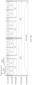
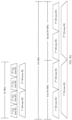
- FIG. 9A is a schematic diagram of a resource unit allocation scenario.
- the bandwidth for transmitting the PPDU is 240 MHz
- a 996-tone RU corresponding to the first 80 MHz subblock in the 240 MHz bandwidth and a 484-tone RU corresponding to the first 40 MHz subblock of the second 80 MHz subblock form a 996+484-tone RU.
- the 996+484-tone RU is allocated to four users.
- the first 80 MHz subblock may be understood as the first to the fourth 20 MHz subblocks
- the second 80 MHz subblock may be understood as the fifth to the eighth 20 MHz subblocks
- the third 80 MHz subblock may be understood as the ninth to the twelfth 20 MHz subblocks.
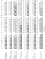
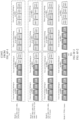
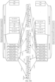
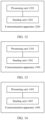
- FIG. 9B is a schematic diagram of a structure of a signal field.
- the signal field indicates a schematic scenario diagram of a resource unit allocation status of a 240 MHz bandwidth.
- the signal field of the PPDU includes a resource unit allocation subfield 1 to a resource unit allocation subfield 6 corresponding to the first 80 MHz subblock in the 240 MHz bandwidth, and a resource unit allocation subfield 7 to a resource unit allocation subfield 12 corresponding to the third 80 MHz subblock in the 240 MHz bandwidth.
- the PPDU is transmitted in two content channels.
- the two content channels may be a content channel 1 and a content channel 2.
- the resource unit allocation subfields 1, 3, 5, 7, 9, and 11 may be transmitted in the content channel 1, and the resource unit allocation subfields 2, 4, 6, 8, 10, and 12 may be transmitted in the content channel 2.
- the resource unit allocation subfield 1 may be indicated by the index 66 in Table 10, to indicate that the first 242-tone RU in the 240 MHz bandwidth belongs to a 996+484-tone RU including a 996-tone RU and a 484-tone RU, the 996+484-tone RU is obtained by combining the first 996-tone RU in a 160 MHz subblock to which the 996+484-tone RU belongs and the third 484-tone RU in the 160 MHz subblock, and two user fields are contributed to a user specific field of a same EHT-SIG content channel (content channel 1) as the resource unit allocation subfield.
- the resource unit allocation subfield 2 may be indicated by the index 66 in Table 10, to indicate that the second 242-tone RU in the 240 MHz bandwidth corresponds to a 996+484-tone RU, the 996+484-tone RU is obtained by combining the first 996-tone RU in a 160 MHz subblock to which the 996+484-tone RU belongs and the third 484-tone RU in the 160 MHz subblock, and two user fields are contributed to a user specific field of a same EHT-SIG content channel (content channel 2) as the resource unit allocation subfield.
- the resource unit allocation subfields 3 to 6 may be indicated by the index 64 in Table 10, to indicate that the corresponding 242-tone RU belongs to a 996+484-tone RU, the 996+484-tone RU is obtained by combining the first 996-tone RU in a 160 MHz subblock to which the 996+484-tone RU belongs and the third 484-tone RU in the 160 MHz subblock, and zero user fields are contributed to a user specific field of a same EHT-SIG content channel as the resource unit allocation subfield.
- the resource unit allocation subfield 7 may be indicated by the index 48 in Table 10, to indicate that the third 242-tone RU of the second 80 MHz subblock in the 240 MHz bandwidth belongs to a 996+484-tone RU, the 484+996-tone RU includes the second 484-tone RU and the second 996-tone RU in a 160 MHz subblock to which the 484+996-tone RU belongs, and two user fields are contributed to a user specific field of a same EHT-SIG content channel (content channel 1) as the resource unit allocation subfield.
- the resource unit allocation subfield 8 may be indicated by the index 47 in Table 10, to indicate that the fourth 242-tone RU of the second 80 MHz subblock in the 240 MHz bandwidth belongs to a 996+484-tone RU, the 484+996-tone RU includes the second 484-tone RU and the second 996-tone RU in a 160 MHz subblock to which the 484+996-tone RU belongs, and one user field is contributed to a user specific field of a same EHT-SIG signal content channel (content channel 2) as the resource unit allocation subfield.
- the resource unit allocation subfields 9 to 12 may be indicated by the index 46 in Table 10, to indicate that the four 242-tone RUs of the third 80 MHz subblock in the 240 MHz bandwidth belong to a 996+484-tone RU, the 484+996-tone RU includes the second 484-tone RU and the second 996-tone RU in a 160 MHz subblock to which the 484+996-tone RU belongs, and zero user fields are contributed to a user specific field of a same EHT-SIG signal content channel as the resource unit allocation subfields.
- arrows indicated by the resource unit allocation subfield 5 and the resource unit allocation subfield 6 are dashed arrows, indicating that the resource unit allocation subfield 5 and the resource unit allocation subfield 6 cannot accurately indicate that the fifth 242-tone RU and the sixth 242-tone RU that are in the 240 MHz bandwidth and that correspond to the resource unit allocation subfield 5 and the resource unit allocation subfield 6 belong to a same MRU as the four 242-tone RUs of the first 80 MHz subblock on the left side in the 240 MHz bandwidth, but still belong to a same MRU as the four 242-tone RUs of the third 80 MHz subblock on the right side in the 240 MHz bandwidth.
- Arrows indicated by the resource unit allocation subfield 7 and the resource unit allocation subfield 8 are dashed arrows, indicating that the resource unit allocation subfield 7 and the resource unit allocation subfield 8 cannot accurately indicate that the seventh 242-tone RU and the eighth 242-tone RU that correspond to the resource unit allocation subfield 7 and the resource unit allocation subfield 8 belong to a same MRU as the four 242-tone RUs of the first 80 MHz subblock on the left side in the 240 MHz bandwidth, but still belong to a same MRU as the four 242-tone RUs of the third 80 MHz subblock on the right side in the 240 MHz bandwidth.
- the STA determines, based on the resource unit allocation subfields 1 to 4 corresponding to the first 80 MHz subblock in the 240 MHz bandwidth, that four 242-tone RUs of the first 80 MHz subblock in the 240 MHz bandwidth belong to a 996+484-tone RU, and the 996+484-tone RU includes the first 996-tone RU and the third 484-tone RU in a 160 MHz subblock to which the 996+484-tone RU belongs.
- the 160 MHz subblock to which the 996+484-tone RU belongs is the lowest 160 MHz frequency in the 240 MHz bandwidth.
- the STA may determine that the 996+484-tone RU includes the 996-tone RU corresponding to the first 80 MHz subblock in the 240 MHz bandwidth and the 484-tone RU corresponding to the lowest 40 MHz frequency of the second 80 MHz subblock.
- the STA determines, based on a sum of the numbers of user fields indicated by the resource unit allocation subfields 1 to 6, that a number of user fields corresponding to the 996+484-tone RU is 4.
- the STA further determines, based on the resource unit allocation subfields 9 to 12 corresponding to the third 80 MHz subblock in the 240 MHz bandwidth, that four 242-tone RUs of the third 80 MHz subblock in the 240 MHz bandwidth belong to a 484+996-tone RU, and the 484+996-tone RU includes the second 484-tone RU and the second 996-tone RU in the 160 MHz subblock to which the 484+996-tone RU belongs.
- the 160 MHz subblock to which the 484+996-tone RU belongs is the high-frequency 160 MHz subblock in the 240 MHz bandwidth.
- the STA may determine that the 484+996-tone RU includes a 484-tone RU corresponding to the highest 40 MHz frequency of the second 80 MHz subblock in the 240 MHz bandwidth and a 996-tone RU corresponding to the third 80 MHz subblock.
- the STA determines, based on a sum of the numbers of user fields indicated by the resource unit allocation subfields 7 to 12, that a number of user fields corresponding to the 484+996-tone RU is 3.
- the STA may determine, based on resource unit allocation subfields corresponding to the first 80 MHz subblock and the third 80 MHz subblock in the 240 MHz bandwidth, the number of user fields corresponding to the MRU formed by combining the 996-tone RU and the 484-tone RU. It may be understood that, in such an implementation, the resource unit allocation subfield corresponding to the second 80 MHz subblock corresponding to the 240 MHz bandwidth participates in indicating the number of user fields.
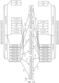
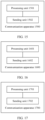
- FIG. 9C is a schematic diagram of a structure of a signal field.
- the signal field of the PPDU includes a resource unit allocation subfield 1 to a resource unit allocation subfield 4 that correspond to the four 242-tone RUs of the first 80 MHz subblock in the 240 MHz bandwidth, a resource unit allocation subfield 5 to a resource unit allocation subfield 8 that correspond to the four 242-tone RUs of the second 80 MHz subblock in the 240 MHz bandwidth, and a resource unit allocation subfield 9 to a resource unit allocation subfield 12 that correspond to the four 242-tone RUs of the third 80 MHz subblock in the 240 MHz bandwidth.
- the PPDU is transmitted in two content channels.
- the two content channels may be a content channel 1 and a content channel 2.
- the resource unit allocation subfields 1, 3, 5, 7, 9, and 11 may be transmitted in the content channel 1, and the resource unit allocation subfields 2, 4, 6, 8, 10, and 12 may be transmitted in the content channel 2.
- manners of indicating the resource unit allocation subfields 1 to 6 and manners of indicating the resource unit allocation subfields 9 to 12 refer to the manners of indicating the resource unit allocation subfields 1 to 6 and the manners of indicating the resource unit allocation subfields 9 to 12 in the examples corresponding to FIG. 9B .
- the resource unit allocation subfields 7 and 8 may be indicated by the index 46 in Table 10, to indicate that the seventh 242-tone RU and the eighth 242-tone RU in the 240 MHz bandwidth belong to a 484+996-tone RU, the 484+996-tone RU includes the second 484-tone RU and the second 996-tone RU in a 160 MHz subblock to which the 484+996-tone RU belongs, and zero user fields are contributed to a user specific field of a same EHT-SIG signal content channel as the resource unit allocation subfields.
- the STA when determining the 996-tone RU and the 484-tone RU that form the MRU, the STA skips the resource unit allocation subfields 5 to 8 corresponding to the second 80 MHz subblock in the 240 MHz bandwidth, and determines, based on resource unit allocation subfields (the resource unit allocation subfields 1 to 4 and 9 to 12) corresponding to the first 80 MHz subblock and the third 80 MHz subblock in the 240 MHz bandwidth, the frequency locations of the 996-tone RU and the 484-tone RU that form the MRU in the 240 MHz bandwidth and the number of user fields corresponding to each MRU.
- resource unit allocation subfields the resource unit allocation subfields 1 to 4 and 9 to 12
- the STA determines, based on the resource unit allocation subfields 1 to 4 corresponding to the first 80 MHz subblock in the 240 MHz bandwidth, that four 242-tone RUs of the first 80 MHz subblock in the 240 MHz bandwidth belong to a 996+484-tone RU, the 996+484-tone RU includes a 996-tone RU corresponding to the first 80 MHz subblock in the 240 MHz bandwidth and a 484-tone RU corresponding to the lowest 40 MHz frequency of the second 80 MHz subblock, and a number of user fields corresponding to the 996+484-tone RU is 4.
- the STA further determines, based on the resource unit allocation subfields 9 to 12 corresponding to the third 80 MHz subblock in the 240 MHz bandwidth, that four 242-tone RUs of the third 80 MHz subblock in the 240 MHz bandwidth belong to the 484+996-tone RU, the 484+996-tone RU includes a 484-tone RU corresponding to the highest 40 MHz frequency of the second 80 MHz subblock in the 240 MHz bandwidth and a 996-tone RU corresponding to the third 80 MHz subblock, and a number of user fields corresponding to the 484+996-tone RU is 3.
- the STA that receives the PPDU determines, based on the resource unit allocation subfields of the first 80 MHz subblock and the third 80 MHz subblock in the 240 MHz bandwidth, that the 240 MHz bandwidth includes two MRUs, the frequency locations of the 996-tone RU and the 484-tone RU that form each MRU in the 240 MHz bandwidth, and the number of user fields corresponding to each MRU.
- FIG. 9A is a schematic diagram of a resource unit allocation scenario.
- the bandwidth for transmitting the PPDU is 240 MHz
- the first to the sixth 242-tone RUs belong to one 996+484-tone RU
- the 996+484-tone RU is allocated to four users.
- the seventh to the twelfth 20 MHz subblocks corresponds to one 484+996-tone RU, and the 484+996 RU is allocated to three users.
- the STA can determine, based on the indices 10 to 18 in Table 11, that the 484+996-tone RU is obtained by combining the second 484-tone RU in the low-frequency 160 MHz subblock in the 240 MHz bandwidth and the second 996-tone RU in the 160 MHz subblock.
- the STA can determine, based on the indices 19 to 27 in Table 11, that the 996+484-tone RU is obtained by combining the first 996-tone RU in the low-frequency 160 MHz subblock in the 240 MHz bandwidth and the fourth 484-tone RU in the 160 MHz subblock.
- the STA can determine, based on the indices 46 to 54, that the 484+996-tone RU is obtained by combining the second 484-tone RU in the high-frequency 160 MHz subblock in the 240 MHz bandwidth and the second 996-tone RU in the 160 MHz subblock.
- the STA can determine, based on the indices 55 to 63 in Table 11, that the 996+484-tone RU is obtained by combining the first 996-tone RU in the high-frequency 160 MHz subblock in the 240 MHz bandwidth and the fourth 484-tone RU in the 160 MHz subblock.
- the indices 64 to 72 indicate that 242-tone RUs corresponding to the resource unit allocation subfields belong to a 996+484-tone RU, an RU number of a 996-tone RU forming the 996+484-tone RU in the 996+484-tone RU is 1, an RU number of a 484-tone RU forming the 996+484-tone RU in the 996+484-tone RU is 3, and the 160 MHz subblock is high-frequency 160 MHz in the 240 MHz bandwidth, that is, 160 MHz on the right side.
- the STA can determine, based on the indices 64 to 72 in Table 11, that the 996+484-tone RU is obtained by combining the first 996-tone RU in the high-frequency 160 MHz subblock in the 240 MHz bandwidth and the third 484-tone RU in the 160 MHz subblock.
- Any index in Table 11 indicates a type of MRU to which a 242-tone RU corresponding to a resource unit allocation subfield belongs, indicates RU numbers of RUs forming the MRU in a segment of consecutive frequencies to which the MRU belongs and a frequency of the segment of consecutive frequencies in the bandwidth, and indicates a number of user fields contributed to a user specific field of a same EHT-SIG content channel as the resource unit allocation subfield.
- any index indicating that a number of user fields is 1 to 8 in Table 11 may include an RU allocation indicating part and a user field indicating part.
- the RU allocation indicating part indicates a type of MRU to which a 242-tone RU corresponding to a resource unit allocation subfield belongs, indicates RU numbers of RUs forming the MRU in a segment of consecutive frequencies to which the MRU belongs, and indicates a frequency of the segment of consecutive frequencies in the bandwidth.
- the user field indicating part indicates a number of user fields contributed to a user specific field of a same EHT-SIG content channel as the resource unit allocation subfield.
- a resource unit allocation subfield is indicated by an index in Table 11.
- the signal field of the PPDU may include the resource unit allocation subfield 1 to the resource unit allocation subfield 4 corresponding to the first 80 MHz subblock in the 240 MHz bandwidth, the resource unit allocation subfield 5 to the resource unit allocation subfield 8 corresponding to the second 80 MHz subblock in the 240 MHz bandwidth, and the resource unit allocation subfield 9 to the resource unit allocation subfield 12 corresponding to the third 80 MHz subblock in the 240 MHz bandwidth.
- the PPDU is transmitted in two content channels.
- the two content channels may be a content channel 1 and a content channel 2.
- the resource unit allocation subfields 1, 3, 5, 7, 9, and 11 may be transmitted in the content channel 1, and the resource unit allocation subfields 2, 4, 6, 8, 10, and 12 may be transmitted in the content channel 2.
- the resource unit allocation subfields 5 and 6 may be indicated by indices in the indices 28 to 36 in Table 11.
- the resource unit allocation subfields 7 and 8 may be indicated by the indices 46 to 54 in Table 6.
- the STA determines, based on the resource unit allocation subfields 5 and 6, that the fifth 242-tone RU and the sixth 242-tone RU in the 240 MHz bandwidth belong to a 996+484-tone RU, and the 996+484-tone RU includes the first 996-tone RU and the third 484-tone RU in a 160 MHz subblock to which the 996+484-tone RU belongs.
- the STA may further determine, based on the resource unit allocation subfields 5 and 6, that the 160 MHz subblock to which the 996+484-tone RU belongs is the lowest 160 MHz frequency in the 240 MHz bandwidth.
- the STA may determine that the 996+484-tone RU includes the 996-tone RU corresponding to the first 80 MHz subblock in the 240 MHz bandwidth and the 484-tone RU corresponding to the lowest 40 MHz frequency of the second 80 MHz subblock.
- the STA determines, based on the resource unit allocation subfields 7 and 8, that the seventh 242-tone RU and the eighth 242-tone RU in the 240 MHz bandwidth belong to a 484+996-tone RU, and the 484+996-tone RU includes the second 484-tone RU and the second 996-tone RU in a 160 MHz subblock to which the 484+996-tone RU belongs.
- the STA may further determine, based on the resource unit allocation subfields 7 and 8, that the 160 MHz subblock to which the 484+996-tone RU belongs is high-frequency 160 MHz in the 240 MHz bandwidth.
- the STA may determine that the 484+996-tone RU includes a 484-tone RU corresponding to the highest 40 MHz frequency of the second 80 MHz subblock in the 240 MHz bandwidth and a 996-tone RU corresponding to the third 80 MHz subblock.
- the resource unit allocation subfields 1 to 12 are all resource unit allocation subfields corresponding to the MRU.
- the resource unit allocation subfields 1 to 4 and 9 to 12 may be indicated by the indices in Table 11, or may be indicated by other indices, for example, may be indicated by the indices in Table 9 or Table 10.
- the resource unit allocation subfields 1 to 4 and 9 to 12 indicate numbers of user fields that are in the user specific field and that correspond to the MRU, or may not be for determining numbers of user fields that are in the user specific field and that correspond to the MRU.
- the STA determines, based on a sum of numbers of user fields indicated by the resource unit allocation subfields 1 to 6, a number of user fields corresponding to a 996+484-tone RU that include a 996-tone RU corresponding to the first 80 MHz subblock in the 240 MHz bandwidth and a 484-tone RU corresponding to the lowest 40 MHz frequency of the second 80 MHz subblock.
- the STA determines, based on a sum of numbers of user fields indicated by the resource unit allocation subfields 5 and 6, a number of user fields corresponding to a 996+484-tone RU that include a 996-tone RU corresponding to the first 80 MHz subblock in the 240 MHz bandwidth and a 484-tone RU corresponding to the lowest 40 MHz frequency of the second 80 MHz subblock.
- the STA determines, based on a sum of numbers of user fields indicated by the resource unit allocation subfields 7 to 12, a number of user fields corresponding to a 484+996-tone RU that include a 484-tone RU corresponding to the highest 40 MHz frequency of the second 80 MHz subblock in the 240 MHz bandwidth and a 996-tone RU corresponding to the third 80 MHz subblock.
- the STA determines, based on a sum of numbers of user fields indicated by the resource unit allocation subfields 7 and 8, a number of user fields corresponding to a 484+996-tone RU that include a 484-tone RU corresponding to the highest 40 MHz frequency of the second 80 MHz subblock in the 240 MHz bandwidth and a 996-tone RU corresponding to the third 80 MHz subblock.
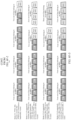
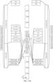
- FIG. 11A is a schematic diagram of a structure of the signal field.
- the resource unit allocation subfields 1 to 4 and 9 to 12 may be indicated by the indices in Table 11.
- the resource unit allocation subfields 1 to 4 indicate the numbers of user fields that are in the user specific fields and that correspond to the MRU.
- the resource unit allocation subfield 1 may be indicated by the index 30 in Table 11, to indicate that the first 242-tone RU belongs to a 996+484-tone RU, the 996+484-tone RU is obtained by combining the first 996-tone RU in a 160 MHz subblock to which the 996+484-tone RU belongs and the third 484-tone RU in the 160 MHz subblock, and the 160 MHz subblock is a 160 MHz subblock on the left side in the 240 MHz bandwidth, and to indicate that two user fields are contributed to a user specific field of a same EHT-SIG content channel (content channel 1) as the resource unit allocation subfield.
- content channel 1 EHT-SIG content channel
- the resource unit allocation subfield 2 may be indicated by the index 30 in Table 11, to indicate that the second 242-tone RU in the 240 MHz bandwidth corresponds to a 996+484-tone RU, the 996+484-tone RU is obtained by combining the first 996-tone RU in a 160 MHz subblock to which the 996+484-tone RU belongs and the third 484-tone RU in the 160 MHz subblock, and the 160 MHz subblock is a 160 MHz subblock on the left side in the 240 MHz bandwidth, and to indicate that two user fields are contributed to a user specific field of a same EHT-SIG content channel (content channel 2) as the resource unit allocation subfield.
- content channel 2 EHT-SIG content channel
- the resource unit allocation subfield 3 to the resource unit allocation subfield 6 may be indicated by the index 28 in Table 11, to indicate that a corresponding 20 MHz subblock belongs to a 996+484-tone RU, the 996+484-tone RU is obtained by combining the first 996-tone RU in a 160 MHz subblock to which the 996+484-tone RU belongs and the third 484-tone RU in the 160 MHz subblock, and the 160 MHz subblock is a 160 MHz subblock on the left side in the 240 MHz bandwidth, and to indicate that zero user fields are contributed to a user specific field of a same EHT-SIG content channel as the resource unit allocation subfield.
- the resource unit allocation subfield 7 may be indicated by the index 48 in Table 11, to indicate that the seventh 242-tone RU in the 240 MHz bandwidth belongs to a 484+996 tone RU, the 484+996 tone RU is obtained by combining the second 484-tone RU and the second 996-tone RU in a 160 MHz subblock to which the 484+996 tone RU belongs, and the 160 MHz subblock is a 160 MHz subblock on the left side in the 240 MHz bandwidth, and to indicate that two user fields are contributed to a user specific field of a same EHT-SIG content channel (content channel 1) as the resource unit allocation subfield.
- content channel 1 content channel 1
- the resource unit allocation subfield 8 may be indicated by the index 47 in Table 11, to indicate that the seventh 242-tone RU in the 240 MHz bandwidth belongs to a 484+996 tone RU, the 484+996 tone RU includes the second 484-tone RU and the second 996-tone RU in a 160 MHz subblock to which the 484+996 tone RU belongs, and the 160 MHz subblock is a 160 MHz subblock on the left side in the 240 MHz bandwidth, and to indicate that one user field is contributed to a user specific field of a same EHT-SIG content channel (content channel 2) as the resource unit allocation subfield.
- any one of the resource unit allocation subfields 1 to 12 may indicate that a corresponding 242-tone RU belongs to an MRU formed by combining a 484-tone RU and a 996-tone RU, and indicate frequency locations of the 484-tone RU and the 996-tone RU that form the 484+996-tone RU in a 160 MHz subblock to which the MRU belongs and a frequency location of the 160 MHz subblock in the 240 MHz bandwidth, to indicate the frequency locations of the 484-tone RU and the 996-tone RU that form the MRU in the 240 MHz bandwidth in which the MRU is located.
- any one of the resource unit allocation subfields 1 to 12 can accurately indicate a specific 484-tone RU and a specific 996-tone RU of a specific 80 MHz subblock included in an MRU indicated by the resource unit allocation subfield.
- a resource unit allocation subfield 5 corresponding to the fifth 20 MHz subblock in the 240 MHz bandwidth may be indicated by the index 30 in Table 11, to indicate that the first 996-tone RU and the third 484-tone RU of the lowest 160 MHz frequency in the 240 MHz bandwidth form a 996+484-tone RU, and the 996+484-tone RU contributes two user fields to a user specific field in a same EHT-SIG content channel as this resource unit allocation subfield.
- a resource unit allocation subfield 6 corresponding to the sixth 20 MHz subblock in the 240 MHz bandwidth may be indicated by the index 30 in Table 11, to indicate that the first 996-tone RU and the third 484-tone RU of the lowest 160 MHz frequency in the 240 MHz bandwidth form a 996+484-tone RU, and the 996+484-tone RU contributes two user fields to a user specific field in a same EHT-SIG content channel as this resource unit allocation subfield.
- a resource unit allocation subfield 7 corresponding to the seventh 20 MHz subblock in the 240 MHz bandwidth may be indicated by the index 48 in Table 11, to indicate that the second 484-tone RU and the second 996-tone RU of the highest 160 MHz frequency in the 240 MHz bandwidth form a 484+996-tone RU, and the 484+996-tone RU contributes two user fields to a user specific field in a same EHT-SIG content channel as this resource unit allocation subfield.
- the 160 MHz subblock that is allowed to include a 996+484-tone RU or a 484+996-tone RU is fixed.
- a 996-tone RU and a 484-tone RU in only a primary 160 MHz subblock (160 MHz subblock including a primary 80 MHz subblock and a secondary 80 MHz subblock) in the 240 MHz bandwidth can be combined into a 996+484-tone RU or a 484+996-tone RU.
Landscapes
- Engineering & Computer Science (AREA)
- Signal Processing (AREA)
- Computer Networks & Wireless Communication (AREA)
- Mobile Radio Communication Systems (AREA)
- Addition Polymer Or Copolymer, Post-Treatments, Or Chemical Modifications (AREA)
- Transition And Organic Metals Composition Catalysts For Addition Polymerization (AREA)
- Catalysts (AREA)
Applications Claiming Priority (3)
| Application Number | Priority Date | Filing Date | Title |
|---|---|---|---|
| CN202010625292.3A CN113891460A (zh) | 2020-07-01 | 2020-07-01 | 一种ppdu的传输方法及相关装置 |
| PCT/CN2021/104045 WO2022002206A1 (zh) | 2020-07-01 | 2021-07-01 | 一种ppdu的传输方法及相关装置 |
| EP21833515.6A EP4171142B1 (de) | 2020-07-01 | 2021-07-01 | Ppdu-übertragungsverfahren und zugehörige vorrichtung |
Related Parent Applications (1)
| Application Number | Title | Priority Date | Filing Date |
|---|---|---|---|
| EP21833515.6A Division EP4171142B1 (de) | 2020-07-01 | 2021-07-01 | Ppdu-übertragungsverfahren und zugehörige vorrichtung |
Publications (2)
| Publication Number | Publication Date |
|---|---|
| EP4583478A2 true EP4583478A2 (de) | 2025-07-09 |
| EP4583478A3 EP4583478A3 (de) | 2025-10-15 |
Family
ID=79012226
Family Applications (2)
| Application Number | Title | Priority Date | Filing Date |
|---|---|---|---|
| EP21833515.6A Active EP4171142B1 (de) | 2020-07-01 | 2021-07-01 | Ppdu-übertragungsverfahren und zugehörige vorrichtung |
| EP25154006.8A Pending EP4583478A3 (de) | 2020-07-01 | 2021-07-01 | Ppdu-übertragungsverfahren und zugehörige vorrichtung |
Family Applications Before (1)
| Application Number | Title | Priority Date | Filing Date |
|---|---|---|---|
| EP21833515.6A Active EP4171142B1 (de) | 2020-07-01 | 2021-07-01 | Ppdu-übertragungsverfahren und zugehörige vorrichtung |
Country Status (9)
| Country | Link |
|---|---|
| US (1) | US20230137534A1 (de) |
| EP (2) | EP4171142B1 (de) |
| JP (3) | JP7559201B2 (de) |
| CN (2) | CN113891460A (de) |
| AU (2) | AU2021302193B2 (de) |
| BR (1) | BR112022027077A2 (de) |
| CA (2) | CA3184861A1 (de) |
| MX (1) | MX2023000220A (de) |
| WO (1) | WO2022002206A1 (de) |
Families Citing this family (10)
| Publication number | Priority date | Publication date | Assignee | Title |
|---|---|---|---|---|
| CN114946250B (zh) * | 2019-11-21 | 2025-06-24 | Lg电子株式会社 | 无线lan系统中通过多个ru接收ppdu的方法及装置 |
| CN113133116A (zh) * | 2020-01-10 | 2021-07-16 | 华为技术有限公司 | 资源单元合并指示的方法和通信装置 |
| US11870735B2 (en) * | 2020-07-28 | 2024-01-09 | Mediatek Singapore Pte. Ltd. | Simplification for distributed-tone resource units in 6GHz low-power indoor systems |
| EP4304115A4 (de) * | 2021-03-04 | 2025-01-22 | LG Electronics Inc. | Verfahren und vorrichtung zur konfiguration des räumlichen wiederverwendungsfeldes eines auslöserrahmens zur auslösung von tba-ppdu in einem wlan-system |
| CN114710412B (zh) * | 2022-03-08 | 2024-04-12 | 中电科思仪科技股份有限公司 | 一种网络协议信号模拟系统及方法 |
| WO2023168709A1 (en) * | 2022-03-11 | 2023-09-14 | Guangdong Oppo Mobile Telecommunications Corp., Ltd. | Access point, station, and wireless communication method |
| US20250211381A1 (en) * | 2022-04-01 | 2025-06-26 | Lg Electronics Inc. | Method and device for resource unit allocation in wireless lan system |
| WO2023237111A1 (en) * | 2022-06-10 | 2023-12-14 | Mediatek Inc. | Designs of multi-ru in wider bandwidth ppdu for next-generation wlan |
| CN117676783A (zh) * | 2022-09-07 | 2024-03-08 | 华为技术有限公司 | 通信方法及装置 |
| CN119728005A (zh) * | 2023-09-28 | 2025-03-28 | 华为技术有限公司 | 通信方法及装置 |
Family Cites Families (11)
| Publication number | Priority date | Publication date | Assignee | Title |
|---|---|---|---|---|
| US10693532B2 (en) * | 2014-09-03 | 2020-06-23 | Newracom, Inc. | Operation method of station in wireless local area network |
| CN106797295B (zh) * | 2014-10-05 | 2020-07-03 | Lg 电子株式会社 | 在wlan中基于单个资源单元分配无线资源的方法和装置 |
| US10602510B2 (en) * | 2015-09-11 | 2020-03-24 | Lg Electronics Inc. | Operation method in wireless LAN system and apparatus therefor |
| EP3742638A1 (de) * | 2015-09-11 | 2020-11-25 | Interdigital Patent Holdings, Inc. | Zuweisung mehrerer ressourceneinheiten für ofdma-wlan |
| US10594450B2 (en) * | 2016-02-15 | 2020-03-17 | Apple Inc. | Asymmetric OFDMA tone mapping and dynamic channel access using non-primary channels |
| CN115085884B (zh) * | 2016-03-04 | 2023-12-12 | 松下知识产权经营株式会社 | 用于站装置的集成电路 |
| US20190069298A1 (en) * | 2017-10-31 | 2019-02-28 | Intel IP Corporation | Enhanced high efficiency frames for wireless communications |
| CN110768757A (zh) * | 2018-07-25 | 2020-02-07 | 华为技术有限公司 | 资源单元指示方法、装置及存储介质 |
| US11343035B2 (en) * | 2019-03-11 | 2022-05-24 | Intel Corporation | Coding over multiple resource units (RU) in extremely high throughput (EHT) systems |
| CN116347617B (zh) * | 2020-04-22 | 2023-09-29 | 华为技术有限公司 | 数据传输方法及相关装置 |
| CN113873645A (zh) * | 2020-06-30 | 2021-12-31 | 华为技术有限公司 | 一种多资源单元传输的指示方法及相关设备 |
-
2020
- 2020-07-01 CN CN202010625292.3A patent/CN113891460A/zh active Pending
- 2020-07-01 CN CN202310368629.0A patent/CN116390250B/zh active Active
-
2021
- 2021-07-01 MX MX2023000220A patent/MX2023000220A/es unknown
- 2021-07-01 BR BR112022027077A patent/BR112022027077A2/pt unknown
- 2021-07-01 CA CA3184861A patent/CA3184861A1/en active Pending
- 2021-07-01 AU AU2021302193A patent/AU2021302193B2/en active Active
- 2021-07-01 JP JP2023500073A patent/JP7559201B2/ja active Active
- 2021-07-01 WO PCT/CN2021/104045 patent/WO2022002206A1/zh not_active Ceased
- 2021-07-01 EP EP21833515.6A patent/EP4171142B1/de active Active
- 2021-07-01 CA CA3295690A patent/CA3295690A1/en active Pending
- 2021-07-01 EP EP25154006.8A patent/EP4583478A3/de active Pending
-
2022
- 2022-12-30 US US18/148,671 patent/US20230137534A1/en active Pending
-
2024
- 2024-09-11 AU AU2024219608A patent/AU2024219608B2/en active Active
- 2024-09-13 JP JP2024159200A patent/JP2025000696A/ja active Pending
- 2024-09-18 JP JP2024161259A patent/JP2025000708A/ja active Pending
Also Published As
| Publication number | Publication date |
|---|---|
| CA3184861A1 (en) | 2022-01-06 |
| JP2025000696A (ja) | 2025-01-07 |
| EP4171142B1 (de) | 2025-02-26 |
| US20230137534A1 (en) | 2023-05-04 |
| JP7559201B2 (ja) | 2024-10-01 |
| MX2023000220A (es) | 2023-02-09 |
| CN113891460A (zh) | 2022-01-04 |
| JP2023533942A (ja) | 2023-08-07 |
| JP2025000708A (ja) | 2025-01-07 |
| CN116390250B (zh) | 2024-01-09 |
| CN116390250A (zh) | 2023-07-04 |
| BR112022027077A2 (pt) | 2023-05-09 |
| AU2024219608A1 (en) | 2024-10-03 |
| AU2024219608B2 (en) | 2026-01-22 |
| EP4583478A3 (de) | 2025-10-15 |
| KR20230029916A (ko) | 2023-03-03 |
| WO2022002206A1 (zh) | 2022-01-06 |
| AU2021302193B2 (en) | 2024-06-13 |
| AU2021302193A1 (en) | 2023-02-09 |
| EP4171142A4 (de) | 2023-12-27 |
| EP4171142A1 (de) | 2023-04-26 |
| CA3295690A1 (en) | 2026-03-02 |
| EP4171142C0 (de) | 2025-02-26 |
Similar Documents
| Publication | Publication Date | Title |
|---|---|---|
| EP4171142B1 (de) | Ppdu-übertragungsverfahren und zugehörige vorrichtung | |
| US11818690B2 (en) | WLAN system resource indication method and apparatus | |
| US11979342B2 (en) | Resource indication method, access point, and station | |
| US12538340B2 (en) | Data transmission for signaling fields in a physical layer protocol data unit | |
| CN112217548A (zh) | 多用户多输入多输出的用户数指示方法和通信装置 | |
| US12136970B2 (en) | Data transmission method and related apparatus | |
| US12580696B2 (en) | Resource unit combination indication method and communication apparatus | |
| KR102955371B1 (ko) | Ppdu 전송 방법 및 관련 장치 | |
| US20260122657A1 (en) | Data transmission method and related apparatus | |
| KR20260058232A (ko) | Ppdu 전송 방법 및 관련 장치 |
Legal Events
| Date | Code | Title | Description |
|---|---|---|---|
| PUAI | Public reference made under article 153(3) epc to a published international application that has entered the european phase |
Free format text: ORIGINAL CODE: 0009012 |
|
| STAA | Information on the status of an ep patent application or granted ep patent |
Free format text: STATUS: THE APPLICATION HAS BEEN PUBLISHED |
|
| AC | Divisional application: reference to earlier application |
Ref document number: 4171142 Country of ref document: EP Kind code of ref document: P |
|
| AK | Designated contracting states |
Kind code of ref document: A2 Designated state(s): AL AT BE BG CH CY CZ DE DK EE ES FI FR GB GR HR HU IE IS IT LI LT LU LV MC MK MT NL NO PL PT RO RS SE SI SK SM TR |
|
| REG | Reference to a national code |
Ref country code: DE Ref legal event code: R079 Free format text: PREVIOUS MAIN CLASS: H04L0027260000 Ipc: H04L0005000000 |
|
| PUAL | Search report despatched |
Free format text: ORIGINAL CODE: 0009013 |
|
| AK | Designated contracting states |
Kind code of ref document: A3 Designated state(s): AL AT BE BG CH CY CZ DE DK EE ES FI FR GB GR HR HU IE IS IT LI LT LU LV MC MK MT NL NO PL PT RO RS SE SI SK SM TR |
|
| RIC1 | Information provided on ipc code assigned before grant |
Ipc: H04L 5/00 20060101AFI20250910BHEP Ipc: H04W 72/04 20230101ALI20250910BHEP Ipc: H04L 27/26 20060101ALI20250910BHEP Ipc: H04W 84/12 20090101ALN20250910BHEP |
|
| STAA | Information on the status of an ep patent application or granted ep patent |
Free format text: STATUS: REQUEST FOR EXAMINATION WAS MADE |