EP4583418A1 - Mimo-systemmodul - Google Patents
Mimo-systemmodul Download PDFInfo
- Publication number
- EP4583418A1 EP4583418A1 EP24222929.2A EP24222929A EP4583418A1 EP 4583418 A1 EP4583418 A1 EP 4583418A1 EP 24222929 A EP24222929 A EP 24222929A EP 4583418 A1 EP4583418 A1 EP 4583418A1
- Authority
- EP
- European Patent Office
- Prior art keywords
- radio frequency
- frequency signals
- outputs
- routing
- inputs
- Prior art date
- Legal status (The legal status is an assumption and is not a legal conclusion. Google has not performed a legal analysis and makes no representation as to the accuracy of the status listed.)
- Pending
Links
Images




Classifications
-
- H—ELECTRICITY
- H04—ELECTRIC COMMUNICATION TECHNIQUE
- H04B—TRANSMISSION
- H04B1/00—Details of transmission systems, not covered by a single one of groups H04B3/00 - H04B13/00; Details of transmission systems not characterised by the medium used for transmission
- H04B1/38—Transceivers, i.e. devices in which transmitter and receiver form a structural unit and in which at least one part is used for functions of transmitting and receiving
- H04B1/40—Circuits
- H04B1/44—Transmit/receive switching
-
- H—ELECTRICITY
- H04—ELECTRIC COMMUNICATION TECHNIQUE
- H04B—TRANSMISSION
- H04B7/00—Radio transmission systems, i.e. using radiation field
- H04B7/02—Diversity systems; Multi-antenna system, i.e. transmission or reception using multiple antennas
- H04B7/04—Diversity systems; Multi-antenna system, i.e. transmission or reception using multiple antennas using two or more spaced independent antennas
- H04B7/0413—MIMO systems
Definitions
- the present specification relates to handling radio frequency signals in multiple-input-multiple-output (MIMO) systems.
- MIMO multiple-input-multiple-output
- MIMO Multiple Input Multiple Outputs
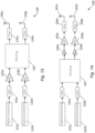
- this specification describes an apparatus comprising: at least two inputs, including first and second inputs for receiving radio frequency signals from first and second transmit chains of a MIMO system respectively; at least two outputs, including first and second outputs for providing radio frequency signals to first and second antenna elements of the MIMO system respectively; and means for routing radio frequency signals, wherein the means for routing radio frequency signals is configured to route radio frequency signals from the first and second inputs to the first and second outputs respectively in a first mode of operation (which may be referred to as a "normal" mode of operation) and to route radio frequency signals from the second input to both the first and second outputs in a second mode of operation in which the first transmit chain is deactivated.
- a first mode of operation which may be referred to as a "normal" mode of operation
- a plurality of inputs, outputs and transmit chains are provided, wherein, in the first mode of operation, the means for routing radio frequency signals is configured to route radio frequency signals from each input to a corresponding output and, in the second mode of operation, at least one of the transmit chains is deactivated and at least one of the inputs is routed, by the means for routing radio frequency signals, to two or more of the outputs.
- the means for routing radio frequency signals comprises: a first switching module for selecting between providing radio frequency signals from the first and second inputs at the first output of said apparatus.
- the means for routing radio frequency signals may further comprise a first phase control module (e.g. a phase shift module) for providing a phase-adjusted (e.g. phase shifted) version of radio frequency signals from the second input, wherein the first switching module is configured to select between providing radio frequency signals from the first input and the phase-adjusted (e.g. phase shifted) version of the radio frequency signals from the second input at the first output.
- the means for routing radio frequency signals may further comprises a second switching module for selecting between providing the radio frequency signals from the second input and the phase-adjusted (e.g. phase shifted) radio frequency signals from the second input at the second output.
- said means for routing said radio frequency signals is provided between power amplifier modules and said antenna elements of the MIMO system.
- said means for routing said radio frequency signals may be provided between baseband processing modules and power amplifier modules of the MIMO system.
- signals of each transmit chain are routed (e.g. using splitter modules) to two or more antenna elements in the first mode of operation.
- the apparatus may further comprise: third and fourth inputs for receiving radio frequency signals from third and fourth transmit chains of the MIMO system respectively; third and fourth outputs for providing radio frequency signals to third and fourth antenna elements of the MIMO system respectively; and a second means for routing radio frequency signals, wherein the second means for routing radio frequency signals is configured to route radio frequency signals from the third and fourth inputs to the third and fourth outputs respectively in the first mode of operation and to route radio frequency signals from the fourth input to both the third and fourth outputs in the second mode of operation in which the third transmit chain is deactivated.
- this specification describes an apparatus comprising: at least two inputs, including first and second inputs for receiving radio frequency signals from first and second antenna elements of a MIMO system respectively; at least two outputs, including first and second outputs for providing radio frequency signals to first and second receiver chains of the MIMO system respectively; and means for routing radio frequency signals, wherein the means for routing radio frequency signals is configured to route radio frequency signals from the first and second antenna elements to the first and second outputs respectively in a first mode of operation and to route radio frequency signals from both the first and second antenna elements to the second output in a second mode of operation in which the first receiver chain is deactivated.
- a plurality of inputs, outputs, antenna elements and receiver chains are provided, wherein, in the first mode of operation, the means for routing radio frequency signals is configured to route radio frequency signals from each input/antenna element to a corresponding output/receiver chain and, in the second mode of operation, at least one of the receiver chains is deactivated and at least one of the inputs/antenna element are routed, by the means for routing radio frequency signals, to common outputs/receiver chains.
- a plurality of inputs, outputs, receiver chains and antenna elements are provided, wherein, in the first mode of operation, the means for routing radio frequency signals is configured to route radio frequency signals from each antenna element to a corresponding output and, in the second mode of operation, at least one of the receiver chains is deactivated and inputs from multiple antenna elements are routed to at least one active receiver chain.
- the means for routing radio frequency signals comprises a first switching module for selecting between providing radio frequency signals from the first antenna element to the first or second receiver chains.
- the means for routing said radio frequency signals may be provided between baseband processing modules and power amplifier modules of the MIMO system.
- the means for routing said radio frequency signals may be provided between power amplifier modules and said antenna elements of the MIMO system.
- the apparatus may further comprise: third and fourth inputs for receiving radio frequency signals from third and fourth antenna elements of the MIMO system respectively; third and fourth outputs for providing radio frequency signals to third and fourth receiver chains of the MIMO system respectively; and a second means for routing radio frequency signals, wherein the second means for routing radio frequency signals is configured to route radio frequency signals from the third and fourth antenna elements to the third and fourth receiver outputs respectively in the first mode of operation and to route radio frequency signals from both the third and fourth antenna elements to the fourth output in the second mode of operation in which the third transmit chain is deactivated.
- this specification describes a MIMO transceiver comprising: a first transceiver chain; a second transceiver chain; first and second antenna elements; a first radio frequency module comprising: at least two inputs, including first and second inputs for receiving radio frequency signals from the first and second transceiver chains respectively in a transmit mode of operation; at least two outputs, including first and second outputs for providing radio frequency signals to the first and second antenna elements respectively; and first means for routing radio frequency signals, wherein the first means for routing radio frequency signals is configured to route radio frequency signals from the first and second inputs to the first and second outputs respectively in a first mode of operation and to route radio frequency signals from the second input to both the first and second outputs in a second mode of operation in which the first transceiver chain is deactivated; and a second radio frequency module comprising: at least two inputs, including first and second inputs for receiving radio frequency signals from the first and second antenna elements respectively in a receive mode of operation; at least two outputs, including first and second
- this specification describes a method comprising: receiving radio frequency signals from first and second transmit chains of a MIMO system at first and second inputs of a radio frequency module respectively, wherein said radio frequency module includes at least two inputs; providing first and second outputs of the radio frequency module to first and second antenna elements of the MIMO system respectively, wherein said radio frequency module includes at least two outputs; routing radio frequency signals from the first and second inputs to the first and second outputs respectively in a first mode of operation; and routing radio frequency signals from the second input to both the first and second outputs in a second mode of operation in which the first transmit chain is deactivated.
- a plurality of inputs, outputs and transmit chains are provided, wherein, in the first mode of operation, radio frequency signals are routed from each input to a corresponding output and, in the second mode of operation, at least one of the transmit chains is deactivated and at least one of the inputs is routed to two or more of the outputs.
- signals of each transmit chain are routed to two or more antenna elements in the first mode of operation.
- the method may further comprise: receiving radio frequency signals from third and fourth transmit chains of the MIMO system at third and fourth inputs of the radio frequency module respectively; providing third and fourth outputs of the radio frequency module to third and fourth antenna elements of the MIMO system respectively; routing radio frequency signals from the third and fourth inputs to the third and fourth outputs respectively in the first mode of operation; and routing radio frequency signals from the fourth input to both the third and fourth outputs in the second mode of operation in which the third transmit chain is deactivated.
- this specification describes a method comprising: receiving radio frequency signals from first and second antenna elements of a MIMO system at first and second inputs of a radio frequency module respectively, wherein said radio frequency module includes at least two inputs; providing radio frequency signals to first and second receiver chains of the MIMO system respectively via first and outputs of the radio frequency module, wherein radio frequency module includes at least two outputs; and routing radio frequency signals from the first and second antenna elements to the first and second outputs respectively in a first mode of operation and routing radio frequency signals from both the first and second antenna elements to the second output in a second mode of operation in which the first receiver chain is deactivated.
- a plurality of inputs, outputs, antenna elements and receiver chains are provided, wherein, in the first mode of operation, the radio frequency signals are routed from each input/antenna element to a corresponding output/receiver chain and, in the second mode of operation, at least one of the receiver chains is deactivated and at least one of the inputs/antenna element are routed to common outputs/receiver chains.
- the radio frequency module may further comprise: third and fourth inputs for receiving radio frequency signals from third and fourth antenna elements of the MIMO system respectively; and third and fourth outputs for providing radio frequency signals to third and fourth receiver chains of the MIMO system respectively.
- Radio frequency signals from the third and fourth antenna elements may be routed to the third and fourth receiver outputs respectively in the first mode of operation.
- radio frequency signals may be routed from both the third and fourth antenna elements to the fourth output in the second mode of operation in which the third transmit chain is deactivated.
- this specification describes computer-readable instructions which, when executed by a computing apparatus, cause the computing apparatus to perform (at least) any method as described herein (including the methods of the fourth and fifth aspects described above).
- this specification describes a computer-readable medium (such as a non-transitory computer-readable medium) comprising program instructions stored thereon for performing (at least) any method as described herein (including the methods of the fourth and fifth aspects described above).
- this specification describes an apparatus comprising: at least one processor; and at least one memory including computer program code which, when executed by the at least one processor, causes the apparatus to perform (at least) any method as described herein (including the methods of the fourth and fifth aspects described above).
- this specification describes a computer program comprising instructions which, when executed by an apparatus, cause the apparatus to: receive radio frequency signals from first and second transmit chains of a MIMO system at first and second inputs of a radio frequency module respectively, wherein said radio frequency module includes at least two inputs; provide first and second outputs of the radio frequency module to first and second antenna elements of the MIMO system respectively, wherein said radio frequency module includes at least two outputs; route radio frequency signals from the first and second inputs to the first and second outputs respectively in a first mode of operation; and route radio frequency signals from the second input to both the first and second outputs in a second mode of operation in which the first transmit chain is deactivated.
- this specification describes an apparatus comprising (at least) first and second inputs (or some other means) for receiving radio frequency signals from first and second antenna elements of a MIMO system respectively; (at least) first and second outputs (or some other means) for providing radio frequency signals to first and second receiver chains of the MIMO system respectively; a routing module (or some other means) for routing radio frequency signals from the first and second antenna elements to the first and second outputs respectively in a first mode of operation; and the routing module (or some other means) for routing radio frequency signals from both the first and second antenna elements to the second output in a second mode of operation in which the first receiver chain is deactivated.
- FIG. 1 is a block diagram of a system, indicated generally by the reference numeral 10, in accordance with an example embodiment.
- the system 10 is a simplified example of a MIMO system.
- the system 10 comprises a precoder 12, a plurality of transceiver chains each having a digital part and an analog part (a first transceiver chain having a digital part 14a and analog part 16a, and a second transceiver chain having a digital part 14b and an analog part 16b are shown in FIG 1 ), and a plurality of antenna elements 18a, 18b.
- a precoder 12 a plurality of transceiver chains each having a digital part and an analog part
- a first transceiver chain having a digital part 14a and analog part 16a, and a second transceiver chain having a digital part 14b and an analog part 16b are shown in FIG 1
- example embodiments may include many more radio frequency chains.
- the system 10 may be used, for example, as part of a 5G massive MIMO (Multiple Inputs Multiple Output) radio unit.
- the size of such a radio unit e.g. the number of RF transceiver chains 14, 16 and antenna elements 18, the silicon size of power amplifiers used, digital processing complexity etc.
- EIRP Effective Isotropic Radiated Power
- maximum capacity of the apparatus which may be defined in terms of maximum Effective Isotropic Radiated Power (EIRP), maximum number of instantaneous beams, maximum RF signal bandwidth etc.
- EIRP Effective Isotropic Radiated Power
- radio systems such as the system 10 do not generally operate at maximum capacity at all times (or even most of the time). Energy efficiency considerations need to take into account not only efficiency at maximum capacity, but also efficiency at other capacity levels (e.g. between 0 and 100% capacity).
- Some example embodiments described herein seek to provide high efficiency MIMO system at moderate or low load conditions. This may have advantages in terms of reduced operating costs (OPEX), reduced carbon footprint for operators, and higher hardware lifetime.
- OPEX operating costs
- the example transceiver chain comprises a digital up-converter (DUC) 21, a Crest Factor Reduction (CRF) module 22, and a Digital Predistortion (DPD) module 23 that form the digital part 14 of the transceiver, a digital-to-analog converter (DAC) 24, a driver 25, a power amplifier 26 and filter 27 that form the analog part 16.
- DUC digital up-converter
- CRF Crest Factor Reduction
- DPD Digital Predistortion
- DAC digital-to-analog converter
- driver 25 a power amplifier 26 and filter 27 that form the analog part 16.
- the digital resources are provided to shape the RF signal for the purposes of amplification by the power amplifier 26 (which power amplifier typically consumes most of the energy in the transceiver chain).
- the efficiency curve of the power amplifier 26 is not flat but is typically maximised close to saturation and decreases with backoff.
- Many mobile communication systems e.g. 4G, 5G and 6G systems
- the downlink power is typically linear with cell load, which results in the transmitted power at moderate load conditions being lower than at higher load conditions.
- power amplifier efficiency is typically lower at moderate load conditions than at high load conditions.
- the CFR module 22 can be used to reduce the backoff, whilst the DPD module 23 can be used to compensate for non-linearities introduced by power amplifier saturation.
- More complex power amplifier architectures can be provided having higher efficiency (e.g. class AB/C/E/F, Doherty, etc.) but this is typically at the cost of increased digital resources.
- One approach is muting, in which one or more transceiver chains are deactivated to reduce power consumption in some specific conditions, as discussed further below.
- FIG. 3 is a block diagram of a system, indicated generally by the reference numeral 30, in accordance with an example embodiment.
- the system 30 shows the system 10 described above, in which the first transceiver chain including the digital part 14a and analog part 16a is deactivated (i.e. "muted").
- muting of one or more transceiver chains may be dynamically controlled according to a scheduler decision, with a specific bias circuit to switch each block on and off. This can result in significant energy savings for both digital and analog resources in low load conditions. However, such muting typically suffers from a limitation in line with the RF architecture.
- EIRP can be considered as a linear KPI (Key Performance Indicator) to determine capacity (throughput) of the system.
- KPI Key Performance Indicator
- An unexpected additional 3dB EIRP reduction may damage cell coverage, particularly for users at the cell edge with reduced SINR (Signal to Noise-and-Interference Ratio).
- the modules 80 and 110 can be used to dynamically map RF front end analog resources and antenna array as a downlink and uplink configurable matrices.
- FIG. 14 is a block diagram of a system, indicated generally by the reference numeral 140, in accordance with an example embodiment.
- the system 140 comprises a first transceiver chain comprising a first digital processing module 141a and a first digital-to-analog converter 142a, a second transceiver chain comprising a second digital processing module 141b and a second digital-to-analog converter 142b, a routing module 143, a first output stage comprising a first driver 144a, a first power amplifier 145a, a first filter module 146a and antenna 147a, and a second output stage comprising a second driver 144b, a second power amplifier 145b, a second filter module 146b and antenna 147b.
- FIG. 16 is a block diagram of a system, indicated generally by the reference numeral 160, in accordance with an example embodiment.
- the system 160 includes the splitters 154, phase control modules 155, power amplifiers 156, filters 157 and antenna elements 158 of the system 150 described above and additional comprises a routing module 162 between the power amplifiers and the filters/antenna elements.
- transceivers having two ports are described (i.e. having two transceivers and two antenna elements), the principles described herein are applicable to systems having more ports (e.g. four transceivers and four antenna elements, or eight transceivers and eight antenna elements etc.)
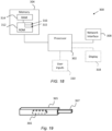
- FIG. 18 is a schematic diagram of components of one or more of the example embodiments described previously, which hereafter are referred to generically as a processing system 300.
- the processing system 300 may, for example, be the apparatus referred to in the claims below.
- the processing system 300 may have a processor 302, a memory 304 closely coupled to the processor and comprised of a RAM 314 and a ROM 312, and, optionally, a user input 310 and a display 318.
- the processing system 300 may comprise one or more network/apparatus interfaces 308 for connection to a network/apparatus, e.g. a modem which may be wired or wireless.
- the network/apparatus interface 308 may also operate as a connection to other apparatus such as device/apparatus which is not network side apparatus. Thus, direct connection between devices/apparatus without network participation is possible.
- the processor 302 is connected to each of the other components in order to control operation thereof.
- the memory 304 may comprise a non-volatile memory, such as a hard disk drive (HDD) or a solid state drive (SSD).
- the ROM 312 of the memory 304 stores, amongst other things, an operating system 315 and may store software applications 316.
- the RAM 314 of the memory 304 is used by the processor 302 for the temporary storage of data.
- the operating system 315 may contain code which, when executed by the processor implements aspects of the algorithms 50, 60 and 100 described above. Note that in the case of small device/apparatus the memory can be most suitable for small size usage i.e. not always a hard disk drive (HDD) or a solid state drive (SSD) is used.
- HDD hard disk drive
- SSD solid state drive
Landscapes
- Engineering & Computer Science (AREA)
- Computer Networks & Wireless Communication (AREA)
- Signal Processing (AREA)
- Radio Transmission System (AREA)
Applications Claiming Priority (1)
| Application Number | Priority Date | Filing Date | Title |
|---|---|---|---|
| FI20245004 | 2024-01-04 |
Publications (1)
| Publication Number | Publication Date |
|---|---|
| EP4583418A1 true EP4583418A1 (de) | 2025-07-09 |
Family
ID=94083143
Family Applications (1)
| Application Number | Title | Priority Date | Filing Date |
|---|---|---|---|
| EP24222929.2A Pending EP4583418A1 (de) | 2024-01-04 | 2024-12-23 | Mimo-systemmodul |
Country Status (2)
| Country | Link |
|---|---|
| US (1) | US20250226848A1 (de) |
| EP (1) | EP4583418A1 (de) |
Citations (1)
| Publication number | Priority date | Publication date | Assignee | Title |
|---|---|---|---|---|
| US20150215024A1 (en) * | 2010-06-11 | 2015-07-30 | Telefonaktiebolaget L M Ericsson (Publ) | Node in a communication system with switchable antenna functions |
-
2024
- 2024-12-23 EP EP24222929.2A patent/EP4583418A1/de active Pending
- 2024-12-31 US US19/006,417 patent/US20250226848A1/en active Pending
Patent Citations (1)
| Publication number | Priority date | Publication date | Assignee | Title |
|---|---|---|---|---|
| US20150215024A1 (en) * | 2010-06-11 | 2015-07-30 | Telefonaktiebolaget L M Ericsson (Publ) | Node in a communication system with switchable antenna functions |
Also Published As
| Publication number | Publication date |
|---|---|
| US20250226848A1 (en) | 2025-07-10 |
Similar Documents
| Publication | Publication Date | Title |
|---|---|---|
| US10171141B2 (en) | Hybrid beam-forming antenna array using selection matrix for antenna phase calibration | |
| KR101581470B1 (ko) | 디지털적으로 구성가능한 적응 선형화를 갖는 최소 피드백 무선 구조 | |
| US20120021697A1 (en) | Radio frequency signal processing circuit and quadrature power amplifier | |
| EP3771112B1 (de) | Verfahren und vorrichtung zur kalibrierung eines sendeempfängers, empfangskanals und sendekanal | |
| US7256649B2 (en) | Multiple signal intermodulation reduction system | |
| JPWO2006118055A1 (ja) | 無線送信装置、ポーラ変調送信装置及び無線通信装置 | |
| US11075606B2 (en) | Power amplifier circuit and antenna device | |
| US10985461B2 (en) | Terminal device | |
| CN110661573B (zh) | 一种rof通信远端机及rof系统 | |
| JP2016100835A (ja) | アクティブアンテナシステム | |
| EP3145144A1 (de) | Sender und interferenzbeseitigungsverfahren | |
| EP1776777B1 (de) | Verfahren und sender mit einer antenne und symmetrischer verstärkerarchitektur zur bereitstellung von leistungsverstärker-lastausgleich unabhängig von einzel- oder doppelsignalbetrieb des senders | |
| EP4583418A1 (de) | Mimo-systemmodul | |
| US9698859B2 (en) | Device for transmitting and receiving carrier aggregation signal | |
| US11936417B2 (en) | Time-division duplex antenna apparatus | |
| CN118487037A (zh) | 自适应频率选择的相控阵天线系统 | |
| CN114553245B (zh) | 一种射频芯片以及通过射频芯片的信号反馈方法 | |
| CN117614504A (zh) | 一种全极化双通道接收组件 | |
| US12425076B1 (en) | System and method for transmitter front-end configurations | |
| JP2016076929A (ja) | アンテナシステム、制御装置、通信装置、及びコンピュータプログラム | |
| CN114785386A (zh) | 高集成射频前端 | |
| KR20200139607A (ko) | 시분할 듀플렉스 안테나 장치 | |
| CN119137859A (zh) | 一种功率放大装置、射频拉远单元、基站以及通信系统 | |
| CN114826342A (zh) | 射频前端芯片及基站用射频前端 | |
| US20070178858A1 (en) | Apparatus and method for transmitting a signal in a communication system |
Legal Events
| Date | Code | Title | Description |
|---|---|---|---|
| PUAI | Public reference made under article 153(3) epc to a published international application that has entered the european phase |
Free format text: ORIGINAL CODE: 0009012 |
|
| STAA | Information on the status of an ep patent application or granted ep patent |
Free format text: STATUS: THE APPLICATION HAS BEEN PUBLISHED |
|
| AK | Designated contracting states |
Kind code of ref document: A1 Designated state(s): AL AT BE BG CH CY CZ DE DK EE ES FI FR GB GR HR HU IE IS IT LI LT LU LV MC ME MK MT NL NO PL PT RO RS SE SI SK SM TR |
|
| STAA | Information on the status of an ep patent application or granted ep patent |
Free format text: STATUS: REQUEST FOR EXAMINATION WAS MADE |
|
| 17P | Request for examination filed |
Effective date: 20251218 |