EP4583389A2 - Energiespeichersystem und startverfahren dafür - Google Patents
Energiespeichersystem und startverfahren dafür Download PDFInfo
- Publication number
- EP4583389A2 EP4583389A2 EP25150444.5A EP25150444A EP4583389A2 EP 4583389 A2 EP4583389 A2 EP 4583389A2 EP 25150444 A EP25150444 A EP 25150444A EP 4583389 A2 EP4583389 A2 EP 4583389A2
- Authority
- EP
- European Patent Office
- Prior art keywords
- voltage
- bus
- electrically connected
- energy storage
- circuit
- Prior art date
- Legal status (The legal status is an assumption and is not a legal conclusion. Google has not performed a legal analysis and makes no representation as to the accuracy of the status listed.)
- Pending
Links
Images


Classifications
-
- H—ELECTRICITY
- H02—GENERATION; CONVERSION OR DISTRIBUTION OF ELECTRIC POWER
- H02M—APPARATUS FOR CONVERSION BETWEEN AC AND AC, BETWEEN AC AND DC, OR BETWEEN DC AND DC, AND FOR USE WITH MAINS OR SIMILAR POWER SUPPLY SYSTEMS; CONVERSION OF DC OR AC INPUT POWER INTO SURGE OUTPUT POWER; CONTROL OR REGULATION THEREOF
- H02M1/00—Details of apparatus for conversion
- H02M1/36—Means for starting or stopping converters
-
- H—ELECTRICITY
- H02—GENERATION; CONVERSION OR DISTRIBUTION OF ELECTRIC POWER
- H02J—ELECTRIC POWER NETWORKS; CIRCUIT ARRANGEMENTS OR SYSTEMS FOR SUPPLYING OR DISTRIBUTING ELECTRIC POWER; SYSTEMS FOR STORING ELECTRIC ENERGY
- H02J9/00—Circuit arrangements for emergency or stand-by power supply, e.g. for emergency lighting
- H02J9/04—Circuit arrangements for emergency or stand-by power supply, e.g. for emergency lighting in which the distribution system is disconnected from the normal source and connected to a standby source
- H02J9/06—Circuit arrangements for emergency or stand-by power supply, e.g. for emergency lighting in which the distribution system is disconnected from the normal source and connected to a standby source with automatic change-over, e.g. UPS systems
-
- H—ELECTRICITY
- H02—GENERATION; CONVERSION OR DISTRIBUTION OF ELECTRIC POWER
- H02J—ELECTRIC POWER NETWORKS; CIRCUIT ARRANGEMENTS OR SYSTEMS FOR SUPPLYING OR DISTRIBUTING ELECTRIC POWER; SYSTEMS FOR STORING ELECTRIC ENERGY
- H02J3/00—Circuit arrangements for AC mains or AC distribution networks
- H02J3/001—Arrangements for handling faults or abnormalities, e.g. emergencies or contingencies
-
- H—ELECTRICITY
- H02—GENERATION; CONVERSION OR DISTRIBUTION OF ELECTRIC POWER
- H02J—ELECTRIC POWER NETWORKS; CIRCUIT ARRANGEMENTS OR SYSTEMS FOR SUPPLYING OR DISTRIBUTING ELECTRIC POWER; SYSTEMS FOR STORING ELECTRIC ENERGY
- H02J3/00—Circuit arrangements for AC mains or AC distribution networks
- H02J3/02—Circuit arrangements for AC mains or AC distribution networks using a single network for simultaneous distribution of AC power at different frequencies
-
- H—ELECTRICITY
- H02—GENERATION; CONVERSION OR DISTRIBUTION OF ELECTRIC POWER
- H02J—ELECTRIC POWER NETWORKS; CIRCUIT ARRANGEMENTS OR SYSTEMS FOR SUPPLYING OR DISTRIBUTING ELECTRIC POWER; SYSTEMS FOR STORING ELECTRIC ENERGY
- H02J3/00—Circuit arrangements for AC mains or AC distribution networks
- H02J3/28—Arrangements for balancing of the load in networks by storage of energy
- H02J3/32—Arrangements for balancing of the load in networks by storage of energy using batteries or super capacitors with converting means
-
- H—ELECTRICITY
- H02—GENERATION; CONVERSION OR DISTRIBUTION OF ELECTRIC POWER
- H02J—ELECTRIC POWER NETWORKS; CIRCUIT ARRANGEMENTS OR SYSTEMS FOR SUPPLYING OR DISTRIBUTING ELECTRIC POWER; SYSTEMS FOR STORING ELECTRIC ENERGY
- H02J2207/00—Details of circuit arrangements for charging or discharging batteries or supplying loads from batteries
- H02J2207/20—Charging or discharging characterised by the power electronics converter
-
- H—ELECTRICITY
- H02—GENERATION; CONVERSION OR DISTRIBUTION OF ELECTRIC POWER
- H02J—ELECTRIC POWER NETWORKS; CIRCUIT ARRANGEMENTS OR SYSTEMS FOR SUPPLYING OR DISTRIBUTING ELECTRIC POWER; SYSTEMS FOR STORING ELECTRIC ENERGY
- H02J7/00—Circuit arrangements for charging or discharging batteries or for supplying loads from batteries
- H02J7/34—Parallel operation in networks using both storage and other DC sources, e.g. providing buffering
- H02J7/345—Parallel operation in networks using both storage and other DC sources, e.g. providing buffering using capacitors as storage or buffering devices
Definitions
- the invention relates to an energy storage system, and particularly to an energy storage system and a start method thereof.
- Self-recovery of the system after power failure of the grid at a large area is generally referred to black start.
- black start When the system is all power failure, the entire system is shut down due to fault and is in a full "black" state.
- the equipment having self-start capability in the system firstly start, and then drive operation of the equipment having no self-start capability, thereby gradually expanding recovery range of the system. And finally achieve recovery of the entire system without assistance of other devices.
- the energy storage system is used as an active system, and after power failure of the grid, energy storage batteries can rapidly supply power for black start equipment.
- a DC/DC converter in the corresponding conversion unit is controlled to release electric energy stored in the corresponding battery pack to charge a DC bus.
- the power of the DC bus supports operation of a power control system (PCS), thereby establishing a three-phase voltage.
- PCS power control system
- the DC/DC converters DD1 and DD2 work in a buck mode, and can also work in a boost mode to satisfy a wide variation range of a voltage of the battery unit and a voltage of the DC bus.
- the voltage of the DC bus shall be established by an input of the DC/DC converter. Since a switch circuit of the DC/DC converter has antiparallel diodes, there is a huge surge impulse current when starting.
- Precharge resistors are arranged when establishing the voltage of the DC bus. However, in design, the power of the precharge resistor is relatively small, which cannot precharge a mF-level capacitor on the DC bus. Moreover, some DC devices connected to the DC bus self-starts when detecting the bus voltage to reach a threshold voltage, which lowers the bus voltage. It is difficult to control an output voltage to reach a target value through the precharge resistor scheme, causing black start failure.
- the existing energy storage system has many issues when black starting, and it is necessary to make improvement.
- an object of the invention is to provide an energy storage system having self-start capability, which can black start successfully, and has a simple structure and a low cost.
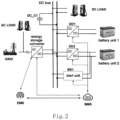
- the invention provides an energy storage system, including: an energy storage converter having an AC end electrically connected to an AC power supply or a load, and a DC end electrically connected to a DC bus; at least one battery unit, each electrically connected to the DC bus through a DC/DC converter; and a start unit electrically connected between a battery unit and the DC bus.
- an energy storage converter having an AC end electrically connected to an AC power supply or a load, and a DC end electrically connected to a DC bus
- at least one battery unit each electrically connected to the DC bus through a DC/DC converter
- a start unit electrically connected between a battery unit and the DC bus.
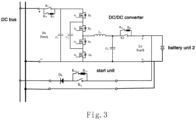
- the start unit includes: a start circuit having an input end electrically connected to the battery unit; and a switching circuit having one end electrically connected to an output end of the start circuit, and the other end electrically connected to the DC bus.
- the set voltage is a voltage of the battery unit; and the switching circuit is a diode having an anode electrically connected to a positive output end of the start circuit, and a cathode electrically connected to the DC bus.
- the switching circuit when the bus voltage is less than the set voltage, the switching circuit is conducted, and the start circuit outputs power to the DC bus; and when the bus voltage is greater than the set voltage, the switching circuit is turned off, and the start circuit stops outputting electric power to the DC bus.
- the set voltage is a voltage of the battery unit; and the switching circuit is a diode having an anode electrically connected to a positive output end of the start circuit, and a cathode electrically connected to the DC bus.
- the at least one DC/DC converter operates to establish the bus voltage from the set voltage to a target voltage through power of the battery unit.
- the start circuit includes a buck circuit having at least one controllable switch, and PWM modulation is performed to the at least one controllable switch.
- the method further includes: judging whether to start the energy storage system through the battery unit; when a judging result is yes, outputting a start command to the start unit; and when the bus voltage is equal to the set voltage, outputting a control signal to the DC/DC converter.
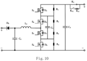
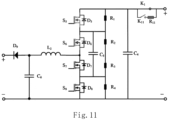
- the start unit BS1 has an input end electrically connected to the battery unit 2, and an output end electrically connected to the DC bus.
- the start unit BS1 is connected in parallel to the DC/DC converter DD2.
- the input end of the start unit BS1 and a low-voltage port of the DC/DC converter DD2 are coupled in parallel to the battery unit 2, and the output end of the start unit BS1 and a high-voltage port of the DC/DC converter DD2 are coupled in parallel to the DC bus.
- the start unit BS 1 only operates when the energy storage system starts from the battery unit. When the start unit BS1 operates, the DC/DC converter DD2 is correspondingly bypassed.
- the start unit BS 1 shares the start process of the DC/DC converter.
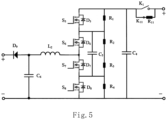
- the second precharge circuit has one end electrically connected to a positive end of the low-voltage port Lv PortB, i.e., a positive electrode of the battery unit, and the other end electrically connected to a first end of the first capacitor C 3 .
- the second precharge circuit includes a second precharge resistor R 21 , a second precharge switch K 21 and a second main switch K 2 .
- the second precharge resistor R 21 and the second precharge switch K 21 are connected in series, and the second main switch K 2 is connected in parallel with the series connection of the second precharge resistor R 21 and the second precharge switch K 21 .
Landscapes
- Engineering & Computer Science (AREA)
- Power Engineering (AREA)
- Business, Economics & Management (AREA)
- Emergency Management (AREA)
- Dc-Dc Converters (AREA)
- Supply And Distribution Of Alternating Current (AREA)
Applications Claiming Priority (1)
| Application Number | Priority Date | Filing Date | Title |
|---|---|---|---|
| CN202410027508.4A CN117937448A (zh) | 2024-01-08 | 2024-01-08 | 储能系统及启动方法 |
Publications (2)
| Publication Number | Publication Date |
|---|---|
| EP4583389A2 true EP4583389A2 (de) | 2025-07-09 |
| EP4583389A3 EP4583389A3 (de) | 2025-07-16 |
Family
ID=90765706
Family Applications (1)
| Application Number | Title | Priority Date | Filing Date |
|---|---|---|---|
| EP25150444.5A Pending EP4583389A3 (de) | 2024-01-08 | 2025-01-07 | Energiespeichersystem und startverfahren dafür |
Country Status (3)
| Country | Link |
|---|---|
| US (1) | US20250226687A1 (de) |
| EP (1) | EP4583389A3 (de) |
| CN (1) | CN117937448A (de) |
Family Cites Families (12)
| Publication number | Priority date | Publication date | Assignee | Title |
|---|---|---|---|---|
| US6593520B2 (en) * | 2000-02-29 | 2003-07-15 | Canon Kabushiki Kaisha | Solar power generation apparatus and control method therefor |
| US8319483B2 (en) * | 2007-08-06 | 2012-11-27 | Solaredge Technologies Ltd. | Digital average input current control in power converter |
| KR102247391B1 (ko) * | 2016-07-25 | 2021-05-03 | 삼성에스디아이 주식회사 | 배터리 시스템 |
| US11496053B2 (en) * | 2018-07-02 | 2022-11-08 | Delta Electronics, Inc. | Power conversion system with dc-bus pre-charge |
| US11557796B2 (en) * | 2019-07-23 | 2023-01-17 | Cummins Inc. | DC-DC-converter-based active voltage-balancing system and method for parallel battery packs |
| CN111049245B (zh) * | 2019-11-25 | 2022-01-07 | 国网浙江省电力有限公司湖州供电公司 | 一种变电站用高可靠性直流电源及检验方法 |
| CN112542851B (zh) * | 2020-11-23 | 2023-05-30 | 南方电网调峰调频发电有限公司 | 电网黑启动电路及充放电桩 |
| JP7659081B2 (ja) * | 2021-04-09 | 2025-04-08 | ファーウェイ デジタル パワー テクノロジーズ カンパニー リミテッド | エネルギ貯蔵システム、エネルギ貯蔵システムの制御方法、及び太陽光発電システム |
| CN114628804A (zh) * | 2022-03-08 | 2022-06-14 | 深圳奥特迅电力设备股份有限公司 | 蓄电池组在线维护的控制装置、方法及电力系统 |
| CN114629154B (zh) * | 2022-05-07 | 2025-08-29 | 西安光谷电气有限公司 | 一种基于微电网的储能系统的维护装置及控制方法 |
| CN116526531A (zh) * | 2023-04-26 | 2023-08-01 | 华为数字能源技术有限公司 | 一种储能装置及储能装置的控制方法 |
| CN116683060B (zh) * | 2023-08-01 | 2024-02-02 | 深圳奥特迅电力设备股份有限公司 | 蓄电池组维护方法、装置、终端设备及存储介质 |
-
2024
- 2024-01-08 CN CN202410027508.4A patent/CN117937448A/zh active Pending
-
2025
- 2025-01-06 US US19/011,469 patent/US20250226687A1/en active Pending
- 2025-01-07 EP EP25150444.5A patent/EP4583389A3/de active Pending
Also Published As
| Publication number | Publication date |
|---|---|
| CN117937448A (zh) | 2024-04-26 |
| US20250226687A1 (en) | 2025-07-10 |
| EP4583389A3 (de) | 2025-07-16 |
Similar Documents
| Publication | Publication Date | Title |
|---|---|---|
| US20250233524A1 (en) | Auxiliary pre-charging device of power converter pre-charging method and power converter | |
| US20260025000A1 (en) | Control method of power supply circuit, power supply circuit, and energy storage device | |
| US10135266B2 (en) | Battery system for motor vehicle with loss-free switching and automatic charge equalization | |
| US10110110B2 (en) | Power conversion device | |
| EP4583385A1 (de) | Bidirektionaler gleichstromwandler, energiespeichervorrichtung und steuerungsverfahren dafür | |
| KR101417669B1 (ko) | 양방향 컨버터 제어 시스템 | |
| JP2021027749A (ja) | 充放電制御装置およびそれを備えたバッテリ並びに直流給電システム | |
| US20220344968A1 (en) | Electric drive system | |
| EP4135153B1 (de) | Batteriezellenausgleichsschaltung und betriebsverfahren dafür | |
| CN112510792A (zh) | 一种退役电池储能系统的可重构变换器及其控制方法 | |
| CN215120607U (zh) | 一种直流充电桩功率拓扑及直流充电桩 | |
| US12512678B2 (en) | Power supply system and method for controlling output voltage of direct current combiner box | |
| CN112994410A (zh) | 电力电子变压器系统直流母线电容的均压控制装置和方法 | |
| US20230318434A1 (en) | Conversion circuit, conversion circuit precharge control method, and photovoltaic system | |
| JP2026508026A (ja) | 新エネルギー発電、エネルギー貯蔵及びマイクログリッドをブリッジ接続するための直流電源変換装置 | |
| EP4583389A2 (de) | Energiespeichersystem und startverfahren dafür | |
| CN115733121A (zh) | 混合动力电动系统和电源系统及其dc/dc变换器器件过热控制方法 | |
| CN119765850A (zh) | 直流/直流变换器、储能系统及光储系统 | |
| CN218217112U (zh) | 一种dc/dc转换器 | |
| US20230128816A1 (en) | Energy storage device, energy storage system with the same and control method, pre-charging circuit for an energy storage device | |
| KR20210007554A (ko) | 전원 시스템 | |
| EP4068555A1 (de) | Multibatterieumschaltsteuerschaltung, vorrichtung und system sowie steuerungsverfahren | |
| CN112187029B (zh) | 一种直流耗能装置 | |
| US11362578B2 (en) | Power conversion apparatus | |
| KR20210156052A (ko) | 이종 배터리 기반 에너지저장시스템 및 전력변환장치의 제어 방법 |
Legal Events
| Date | Code | Title | Description |
|---|---|---|---|
| PUAI | Public reference made under article 153(3) epc to a published international application that has entered the european phase |
Free format text: ORIGINAL CODE: 0009012 |
|
| STAA | Information on the status of an ep patent application or granted ep patent |
Free format text: STATUS: THE APPLICATION HAS BEEN PUBLISHED |
|
| PUAL | Search report despatched |
Free format text: ORIGINAL CODE: 0009013 |
|
| AK | Designated contracting states |
Kind code of ref document: A2 Designated state(s): AL AT BE BG CH CY CZ DE DK EE ES FI FR GB GR HR HU IE IS IT LI LT LU LV MC ME MK MT NL NO PL PT RO RS SE SI SK SM TR |
|
| AK | Designated contracting states |
Kind code of ref document: A3 Designated state(s): AL AT BE BG CH CY CZ DE DK EE ES FI FR GB GR HR HU IE IS IT LI LT LU LV MC ME MK MT NL NO PL PT RO RS SE SI SK SM TR |
|
| RIC1 | Information provided on ipc code assigned before grant |
Ipc: H02M 1/36 20070101AFI20250606BHEP Ipc: H02J 3/00 20060101ALI20250606BHEP Ipc: H02J 3/32 20060101ALI20250606BHEP Ipc: H02J 7/34 20060101ALN20250606BHEP |
|
| STAA | Information on the status of an ep patent application or granted ep patent |
Free format text: STATUS: REQUEST FOR EXAMINATION WAS MADE |
|
| 17P | Request for examination filed |
Effective date: 20251117 |