EP4583385A1 - Bidirektionaler gleichstromwandler, energiespeichervorrichtung und steuerungsverfahren dafür - Google Patents
Bidirektionaler gleichstromwandler, energiespeichervorrichtung und steuerungsverfahren dafür Download PDFInfo
- Publication number
- EP4583385A1 EP4583385A1 EP25150442.9A EP25150442A EP4583385A1 EP 4583385 A1 EP4583385 A1 EP 4583385A1 EP 25150442 A EP25150442 A EP 25150442A EP 4583385 A1 EP4583385 A1 EP 4583385A1
- Authority
- EP
- European Patent Office
- Prior art keywords
- voltage
- switching tube
- bidirectional
- converter
- port
- Prior art date
- Legal status (The legal status is an assumption and is not a legal conclusion. Google has not performed a legal analysis and makes no representation as to the accuracy of the status listed.)
- Pending
Links
Images


Classifications
-
- H—ELECTRICITY
- H02—GENERATION; CONVERSION OR DISTRIBUTION OF ELECTRIC POWER
- H02M—APPARATUS FOR CONVERSION BETWEEN AC AND AC, BETWEEN AC AND DC, OR BETWEEN DC AND DC, AND FOR USE WITH MAINS OR SIMILAR POWER SUPPLY SYSTEMS; CONVERSION OF DC OR AC INPUT POWER INTO SURGE OUTPUT POWER; CONTROL OR REGULATION THEREOF
- H02M3/00—Conversion of DC power input into DC power output
- H02M3/02—Conversion of DC power input into DC power output without intermediate conversion into AC
- H02M3/04—Conversion of DC power input into DC power output without intermediate conversion into AC by static converters
- H02M3/10—Conversion of DC power input into DC power output without intermediate conversion into AC by static converters using discharge tubes with control electrode or semiconductor devices with control electrode
- H02M3/145—Conversion of DC power input into DC power output without intermediate conversion into AC by static converters using discharge tubes with control electrode or semiconductor devices with control electrode using devices of a triode or transistor type requiring continuous application of a control signal
- H02M3/155—Conversion of DC power input into DC power output without intermediate conversion into AC by static converters using discharge tubes with control electrode or semiconductor devices with control electrode using devices of a triode or transistor type requiring continuous application of a control signal using semiconductor devices only
- H02M3/156—Conversion of DC power input into DC power output without intermediate conversion into AC by static converters using discharge tubes with control electrode or semiconductor devices with control electrode using devices of a triode or transistor type requiring continuous application of a control signal using semiconductor devices only with automatic control of output voltage or current, e.g. switching regulators
- H02M3/158—Conversion of DC power input into DC power output without intermediate conversion into AC by static converters using discharge tubes with control electrode or semiconductor devices with control electrode using devices of a triode or transistor type requiring continuous application of a control signal using semiconductor devices only with automatic control of output voltage or current, e.g. switching regulators including plural semiconductor devices as final control devices for a single load
- H02M3/1582—Buck-boost converters
-
- H—ELECTRICITY
- H02—GENERATION; CONVERSION OR DISTRIBUTION OF ELECTRIC POWER
- H02M—APPARATUS FOR CONVERSION BETWEEN AC AND AC, BETWEEN AC AND DC, OR BETWEEN DC AND DC, AND FOR USE WITH MAINS OR SIMILAR POWER SUPPLY SYSTEMS; CONVERSION OF DC OR AC INPUT POWER INTO SURGE OUTPUT POWER; CONTROL OR REGULATION THEREOF
- H02M3/00—Conversion of DC power input into DC power output
- H02M3/02—Conversion of DC power input into DC power output without intermediate conversion into AC
- H02M3/04—Conversion of DC power input into DC power output without intermediate conversion into AC by static converters
- H02M3/10—Conversion of DC power input into DC power output without intermediate conversion into AC by static converters using discharge tubes with control electrode or semiconductor devices with control electrode
- H02M3/145—Conversion of DC power input into DC power output without intermediate conversion into AC by static converters using discharge tubes with control electrode or semiconductor devices with control electrode using devices of a triode or transistor type requiring continuous application of a control signal
- H02M3/155—Conversion of DC power input into DC power output without intermediate conversion into AC by static converters using discharge tubes with control electrode or semiconductor devices with control electrode using devices of a triode or transistor type requiring continuous application of a control signal using semiconductor devices only
- H02M3/156—Conversion of DC power input into DC power output without intermediate conversion into AC by static converters using discharge tubes with control electrode or semiconductor devices with control electrode using devices of a triode or transistor type requiring continuous application of a control signal using semiconductor devices only with automatic control of output voltage or current, e.g. switching regulators
- H02M3/158—Conversion of DC power input into DC power output without intermediate conversion into AC by static converters using discharge tubes with control electrode or semiconductor devices with control electrode using devices of a triode or transistor type requiring continuous application of a control signal using semiconductor devices only with automatic control of output voltage or current, e.g. switching regulators including plural semiconductor devices as final control devices for a single load
-
- H—ELECTRICITY
- H02—GENERATION; CONVERSION OR DISTRIBUTION OF ELECTRIC POWER
- H02J—ELECTRIC POWER NETWORKS; CIRCUIT ARRANGEMENTS OR SYSTEMS FOR SUPPLYING OR DISTRIBUTING ELECTRIC POWER; SYSTEMS FOR STORING ELECTRIC ENERGY
- H02J7/00—Circuit arrangements for charging or discharging batteries or for supplying loads from batteries
- H02J7/34—Parallel operation in networks using both storage and other DC sources, e.g. providing buffering
- H02J7/345—Parallel operation in networks using both storage and other DC sources, e.g. providing buffering using capacitors as storage or buffering devices
-
- H—ELECTRICITY
- H02—GENERATION; CONVERSION OR DISTRIBUTION OF ELECTRIC POWER
- H02M—APPARATUS FOR CONVERSION BETWEEN AC AND AC, BETWEEN AC AND DC, OR BETWEEN DC AND DC, AND FOR USE WITH MAINS OR SIMILAR POWER SUPPLY SYSTEMS; CONVERSION OF DC OR AC INPUT POWER INTO SURGE OUTPUT POWER; CONTROL OR REGULATION THEREOF
- H02M1/00—Details of apparatus for conversion
- H02M1/0095—Hybrid converter topologies, e.g. NPC mixed with flying capacitor, thyristor converter mixed with MMC or charge pump mixed with buck
-
- H—ELECTRICITY
- H02—GENERATION; CONVERSION OR DISTRIBUTION OF ELECTRIC POWER
- H02M—APPARATUS FOR CONVERSION BETWEEN AC AND AC, BETWEEN AC AND DC, OR BETWEEN DC AND DC, AND FOR USE WITH MAINS OR SIMILAR POWER SUPPLY SYSTEMS; CONVERSION OF DC OR AC INPUT POWER INTO SURGE OUTPUT POWER; CONTROL OR REGULATION THEREOF
- H02M1/00—Details of apparatus for conversion
- H02M1/32—Means for protecting converters other than automatic disconnection
-
- H—ELECTRICITY
- H02—GENERATION; CONVERSION OR DISTRIBUTION OF ELECTRIC POWER
- H02M—APPARATUS FOR CONVERSION BETWEEN AC AND AC, BETWEEN AC AND DC, OR BETWEEN DC AND DC, AND FOR USE WITH MAINS OR SIMILAR POWER SUPPLY SYSTEMS; CONVERSION OF DC OR AC INPUT POWER INTO SURGE OUTPUT POWER; CONTROL OR REGULATION THEREOF
- H02M1/00—Details of apparatus for conversion
- H02M1/36—Means for starting or stopping converters
-
- H—ELECTRICITY
- H02—GENERATION; CONVERSION OR DISTRIBUTION OF ELECTRIC POWER
- H02M—APPARATUS FOR CONVERSION BETWEEN AC AND AC, BETWEEN AC AND DC, OR BETWEEN DC AND DC, AND FOR USE WITH MAINS OR SIMILAR POWER SUPPLY SYSTEMS; CONVERSION OF DC OR AC INPUT POWER INTO SURGE OUTPUT POWER; CONTROL OR REGULATION THEREOF
- H02M3/00—Conversion of DC power input into DC power output
- H02M3/02—Conversion of DC power input into DC power output without intermediate conversion into AC
- H02M3/04—Conversion of DC power input into DC power output without intermediate conversion into AC by static converters
- H02M3/10—Conversion of DC power input into DC power output without intermediate conversion into AC by static converters using discharge tubes with control electrode or semiconductor devices with control electrode
- H02M3/145—Conversion of DC power input into DC power output without intermediate conversion into AC by static converters using discharge tubes with control electrode or semiconductor devices with control electrode using devices of a triode or transistor type requiring continuous application of a control signal
- H02M3/155—Conversion of DC power input into DC power output without intermediate conversion into AC by static converters using discharge tubes with control electrode or semiconductor devices with control electrode using devices of a triode or transistor type requiring continuous application of a control signal using semiconductor devices only
- H02M3/156—Conversion of DC power input into DC power output without intermediate conversion into AC by static converters using discharge tubes with control electrode or semiconductor devices with control electrode using devices of a triode or transistor type requiring continuous application of a control signal using semiconductor devices only with automatic control of output voltage or current, e.g. switching regulators
- H02M3/158—Conversion of DC power input into DC power output without intermediate conversion into AC by static converters using discharge tubes with control electrode or semiconductor devices with control electrode using devices of a triode or transistor type requiring continuous application of a control signal using semiconductor devices only with automatic control of output voltage or current, e.g. switching regulators including plural semiconductor devices as final control devices for a single load
- H02M3/1584—Conversion of DC power input into DC power output without intermediate conversion into AC by static converters using discharge tubes with control electrode or semiconductor devices with control electrode using devices of a triode or transistor type requiring continuous application of a control signal using semiconductor devices only with automatic control of output voltage or current, e.g. switching regulators including plural semiconductor devices as final control devices for a single load with a plurality of power processing stages connected in parallel
- H02M3/1586—Conversion of DC power input into DC power output without intermediate conversion into AC by static converters using discharge tubes with control electrode or semiconductor devices with control electrode using devices of a triode or transistor type requiring continuous application of a control signal using semiconductor devices only with automatic control of output voltage or current, e.g. switching regulators including plural semiconductor devices as final control devices for a single load with a plurality of power processing stages connected in parallel switched with a phase shift, i.e. interleaved
-
- H—ELECTRICITY
- H02—GENERATION; CONVERSION OR DISTRIBUTION OF ELECTRIC POWER
- H02J—ELECTRIC POWER NETWORKS; CIRCUIT ARRANGEMENTS OR SYSTEMS FOR SUPPLYING OR DISTRIBUTING ELECTRIC POWER; SYSTEMS FOR STORING ELECTRIC ENERGY
- H02J2207/00—Details of circuit arrangements for charging or discharging batteries or supplying loads from batteries
- H02J2207/20—Charging or discharging characterised by the power electronics converter
Definitions
- the invention relates to the technical field of black start of the circuit, and particularly to a bidirectional DC/DC converter, an energy storage device and a control method thereof.
- Self-recovery of the system after power failure of the grid at a large area is generally referred to black start.
- black start When the system is all power failure, the entire system is shut down due to fault and is in a full "black" state.
- the equipment having self-start capability in the system firstly start, and then drive operation of the equipment having no self-start capability, thereby gradually expanding a recovery range of the system. And finally achieve recovery of the entire system without assistance of other devices.
- the black start function is implemented by a black start mode of the PCS.
- PCS power control system
- the energy storage system shall add a DC/DC module at a battery side.
- the first structure is that a part of batteries in the system are configured with the DC/DC modules and the other part of batteries are directly connected to the DC bus.
- the DC bus voltage is supplied using a direct-mounted battery, then the DC/DC module is started to control the DC bus voltage, and next black start of the system is completed through the PCS.
- the second structure is that all batteries in the system are configured with the DC/DC modules.
- black starting a self-start DC load equipment is disconnected firstly, then the DC bus capacitor is precharged via antiparallel diodes of the DC/DC module and a precharging resistor R, next the DC/DC module is started to control the DC bus voltage, and black start of the system is completed using the PCS after the DC Load is connected.
- the second structure shall perform the black start operation from a system level, additional large power precharging resistors and high-voltage DC contactors are added, and complexity of the control logic is increased.
- the existing DC converter has more issues when black starting, so it is necessary to make improvement.
- an object of the invention is to provide a bidirectional DC/DC converter having self-start capability and a flexible voltage soft start way, thereby optimizing system hardware topology of the energy storage device.
- the invention provides a bidirectional DC/DC converter.
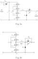
- the bidirectional DC/DC converter includes a low-voltage port having a first voltage, a high-voltage port, a start circuit having one end electrically connected to the low-voltage port, an inductor having one end electrically connected to the other end of the start circuit, and a switch circuit having both ends electrically connected to the high-voltage port and the other end of the inductor, respectively.
- the start circuit includes at least one controllable switch.
- the switch circuit A 2 has a conducting branch formed of antiparallel diodes D 1 and D 2 , and the start circuit A 1 continues to charge the first capacitor C 1 through the conducting branch to continue to establish the voltage of the high-voltage port PortA from 0.5Hv to Lv. Since the maximum voltage of the first flying capacitor C 2 is 0.5Hv, when Lv ⁇ 0.5Hv, at the first working stage, a path for charging the first flying capacitor C 2 shall be cut off when the voltage of the first flying capacitor C 2 reaches 0.5Hv.
- FIG. 7 shows current loops of the bidirectional DC/DC converter in FIG. 3 when the main switching tube S 5 is turned off. Please refer to FIGS. 5 and 7 .
- the main switching tube S 5 is turned off, and the auxiliary switching tube D 6 is turned on.
- the inductor L 1 follows current, and there are two current loops. In one freewheel loop, the current flows through the inductor L 1 , the switching tube S 2 , the first flying capacitor C 2 , the fourth switching tube S 4 and the auxiliary switching tube D 6 .
- FIG. 9 shows a current loop of the bidirectional DC/DC converter in FIG. 3 when the main switching tube S 5 is off. Please refer to FIGS. 5 and 9 .
- the voltage of the first flying capacitor C 2 has been charged to one half of the second voltage Hv, so at this time, the second switching tube S 2 and the fourth switching tube S 4 are turned off, and the first flying capacitor C 2 is no longer charged.
- the main switching tube S 5 is turned off, and the auxiliary switching tube D 6 is turned on.
- the switch circuit A 2 When the first voltage Lv is less than one half of the second voltage Hv, at the second working stage, the switch circuit A 2 operates in the mode A, the mode B and the mode D.
- the switch circuit A 2 operates in the mode D.
- the third switching tube S 3 and the fourth switching tube S 4 are conducted, and the current flows through the inductor L 1 , the third switching tube S 3 and the fourth switching tube S 4 .
- the power of the low-voltage port PortB charges the inductor L 1 .
- the switch circuit A 2 operates in the mode C.
- the second switching tube S 2 and the fourth switching tube S 4 are conducted, and the current flows through the inductor L 1 , the second switching tube S 2 , the first flying capacitor C 2 , the fourth switching tube S 4 and the low-voltage port PortB to charge the first flying capacitor C 2 and the inductor L 1 .
- the switch circuit A 2 operates in the mode D.
- the third switching tube S 3 and the fourth switching tube S 4 are conducted, and the current flows through the inductor L 1 , the third switching tube S 3 and the fourth switching tube S 4 .
- the power of the low-voltage port PortB charges the inductor L 1 .
- the switch circuit A 2 operates in the mode B.
- the first switching tube S 2 and the third switching tube S 3 are conducted, the current flows through the inductor L 1 , the first switching tube S 1 , the first flying capacitor C 2 and the third switching tube S 3 .
- the inductor L 1 releases energy, and the first flying capacitor C 2 discharges.
- the first flying capacitor C 2 , the inductor L 1 and the low-voltage port PortB charge the first capacitor C 1 .
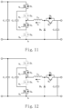
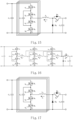
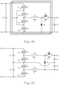
- the switch circuit A 2 and the inductor L 1 of the bidirectional DC/DC converter in any embodiment of FIGS. 1a to 1c are a multi-phase interleaving topological structure, as shown in FIGS. 16 to 17 .
- the switch circuit A 2 , the inductor L 1 and the start circuit A 1 of the bidirectional DC/DC converter in any embodiment of FIGS. 1a to 1c are a multi-phase interleaving topological structure, as shown in FIG. 18 .
- the switch circuit A 2 and the inductors L 11 , L 12 of the bidirectional DC/DC converter in any embodiment of FIGS. 1a to 1c are a cascaded topological structure, as shown in FIG. 19 .
- FIG. 20 shows another schematic circuit diagram of the bidirectional DC/DC converter in FIG. 1c .
- the start circuit A 1 of the bidirectional DC/DC converter in this embodiment is a second flying capacitor switch circuit, and includes a fifth switching tube S 5 , a sixth switching tube S 6 , a seventh switching tube S 7 , an eighth switching tube Ss, a first resistor R 1 , a second resistor R 2 , a third resistor R 3 , a fourth resistor R 4 and a second flying capacitor C 4 .
- the fifth switching tube S 5 , the sixth switching tube S 6 , the seventh switching tube S 7 and the eighth switching tube S 8 are sequentially connected in series.
- a drain electrode of the fifth switching tube S 5 is electrically connected to a first end of the low-voltage port PortB, and a source electrode of the eighth switching tube S 8 is electrically connected to a second end of the low-voltage port PortB.
- a source electrode of the sixth switching tube S 6 is electrically connected to the inductor L 1 .
- the second flying capacitor C 4 is electrically connected in parallel between a drain electrode of the sixth switching tube S 6 and a source electrode of the seventh switching tube S 7 .
- the first resistor R 1 , the second resistor R 2 , the third resistor R 3 and the fourth resistor R 4 are sequentially connected in series.
- FIG. 21 is a schematic diagram of pulse signals of switching tubes in the bidirectional DC/DC converter of FIG. 20 .
- FIG. 21 corresponds to working stages in the case that the first voltage Lv is greater than or equal to one half of the second voltage Hv.
- M 1 ⁇ 4 are carrier waves of the switching tubes S 1 to S 4
- M 5 ⁇ 8 are carrier waves of the switching tubes S 5 to S 8
- S 1 ⁇ S 8 are pulse signals of the switching tubes S 1 to S 8
- D is a modulation signal of the switching tubes S 1 to S 8 . Please refer to FIG.
- pulse widths of switching signals of the fifth switching tube S 5 and the sixth switching tube S 6 are controlled to gradually increase, and pulse widths of switching signals of the seventh switching tube S 7 and the eighth switching tube S 8 are controlled to gradually decrease.
- the voltage of the high-voltage port PortA is gradually established to the first voltage Lv.
- the fifth switching tube S 5 and the sixth switching tube S 6 are controlled to conduct constantly, and the seventh switching tube S 7 and the eighth switching tube S 8 are controlled to be off.
- the seventh switching tube S 7 and the eighth switching tube S 8 are conducted, and the second switching tube S 2 and the fourth switching tube S 4 are conducted.
- the inductor L 1 freewheels, and there are two current loops. In one current loop, the current flows through the second switching tube S 2 , the first flying capacitor C 2 , the fourth switching tube S 4 , the seventh switching tube S 7 and the eighth switching tube S 8 to charge the first flying capacitor C 2 . In the other current loop, the current flows through the second switching tube S 2 , the antiparallel diode D 1 , the first capacitor C 1 , the seventh switching tube S 7 and the eighth switching tube S 8 to charge the first capacitor C 1 .
- FIGS. 21 and 23 Please refer to FIGS. 21 and 23 .
- the sixth switching tube S 6 and the eighth switching tube S 8 are conducted, the second flying capacitor C 4 discharges, and the inductor L 1 freewheels.
- the current flows through the sixth switching tube S 6 , the inductor L 1 , the second switching tube S 2 , the antiparallel diode D 1 , the first capacitor C 1 and the eighth switching tube S 8 and the second flying capacitor C 4 to charge the first capacitor C 1 .
- the fifth switching tube S 8 and the seventh switching tube S 7 are conducted, and the low-voltage port PortB charges the second flying capacitor C 4 .
- the second flying capacitor C 4 and the first flying capacitor C 2 are charged.
- the current flows through the low-voltage port, the fifth switching tube S 5 , the second flying capacitor C 4 , the seventh switching tube S 7 , the inductor L 1 , the second switching tube S 2 , the antiparallel diode D 1 and the first capacitor C 1 , and flows back to the low-voltage port.
- the first capacitor C 1 are charged.
- the fifth switching tube S 5 and the sixth switching tube S 6 are turned on, and the seventh switching tube S 7 and the eighth switching tube S 8 are turned off. There are two current loops. In one current loop, the current flows through the low-voltage port, the fifth switching tube S 5 , the sixth switching tube S 6 , the inductor L 1 , the second switching tube S 2 , the first flying capacitor C 2 and the fourth switching tube S 4 , and flows back to the low-voltage port. As a result, the first flying capacitor C 2 are charged.
- the current flows through the low-voltage port, the fifth switching tube S 5 , the sixth switching tube S 6 , the inductor L 1 , the second switching tube S 2 , the antiparallel diode D 1 and the first capacitor C 1 , and flows back to the low-voltage port.
- the first capacitor C 1 are charged.
- the first working stage of the bidirectional DC/DC converter in FIG. 20 further includes the time period t 5 ⁇ t 9 . Combining with the time period t 5 ⁇ t 9 , operations and corresponding current loops of the start circuit A 1 are explained when the voltage of the first flying capacitor C 2 is charged to 0.5Hv.
- FIGS. 21 and 29 Please refer to FIGS. 21 and 29 .
- the fifth switching tube S 5 and the sixth switching tube S 6 are conducted, and the current of the low-voltage port flows through the fifth switching tube S 5 , the sixth switching tube S 6 , the inductor L 1 , the antiparallel diode D 2 , the antiparallel diode D 1 and the first capacitor C 1 to continue charging the first capacitor C 1 .
- the fifth switching tube S 5 and the seventh switching tube S 7 are conducted, and the current of the low-voltage port flows through the fifth switching tube S5, the second flying capacitor C 4 , the seventh switching tube S 7 , the inductor L 1 , the antiparallel diode D 2 , the antiparallel diode D 1 and the first capacitor C 1 to charge the second flying capacitor C 4 and the first capacitor C 1 .
- FIGS. 21 and 29 Please refer to FIGS. 21 and 29 .
- the fifth switching tube S 5 and the sixth switching tube S 6 are conducted, and the current of the low-voltage port flows through the fifth switching tube S 5 , the sixth switching tube S 6 , the inductor L 1 , the antiparallel diode D 1 , the antiparallel diode D 2 and the first capacitor C 1 to continue charging the first capacitor C 1 .
- FIGS. 21 and 27 Please refer to FIGS. 21 and 27 .
- the sixth switching tube S 6 and the eighth switching tube S 8 are conducted, the second flying capacitor C 4 discharges, and the current flows through the sixth switching tube S 6 , the inductor L 1 , the antiparallel diode D 2 , the antiparallel diode D 1 , the first capacitor C 1 and the eighth switching tube S 8 to continue charging the first capacitor C 1 .
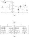
- the invention further provides an energy storage device.
- the energy storage device includes a power condition system (PCS), a DC bus and multiple energy storage units.
- the DC bus is electrically connected to a DC side of the power condition system.
- Each of the multiple energy storage units is electrically connected to the DC bus through a bidirectional DC/DC converter, and at least one bidirectional DC/DC converter (such as, #1A and #20A) includes the low-voltage port, the high-voltage port, the start circuit, the inductor and the switch circuit.
- the energy storage units supply the first voltage to the corresponding low-voltage port of the DC/DC converter, the high-voltage port is electrically connected to the DC bus, and a target voltage of the high-voltage port is the second voltage.
- the second voltage is equal to a voltage reference of the DC bus.
- the start circuit is electrically connected to the low-voltage port, the start circuit includes at least one controllable switch, and one end of the inductor is electrically connected to the other end of the start circuit. Both ends of the switch circuit are electrically connected to the high-voltage port and the other end of the inductor, respectively.
- the at least one controllable switch is modulated, thereby using the first voltage to establish a voltage of the high-voltage port.
- the energy storage device is electrically connected to a power supply system, such as, a grid.
- a power supply system such as, a grid.
- the energy storage units output energy to the at least one bidirectional DC/DC converter (such as, #1A and #20A) to establish a bus voltage through the at least one bidirectional DC/DC converter, thereby achieving the black start of the power condition system.
- FIG. 4 shows a block diagram of the energy storage device.
- a DC side of the power control system (PCS) is electrically connected to the DC bus, the DC bus is electrically connected to high-voltage ports of the several bidirectional DC/DC converters (i.e., DD units 1A, 1B,...), and low-voltage ports of the bidirectional DC/DC converters are electrically connected to the corresponding energy storage units.
- the energy storage device receives a black start command, it is unnecessary for DC devices mounted on the DC bus to make special switching, and the bidirectional DC/DC converter directly performs black start operation to establish a DC bus voltage in soft-start. In actual application, only add the start circuit A 1 in several groups of bidirectional DC/DC converters.
- the bidirectional DC/DC converters with the start circuit own black start capability can establish the bus voltage. After the DC bus voltage is established, the remaining modules are connected to the grid to start, and it is unnecessary that all bidirectional DC/DC converters are configured with the start circuit A 1 , thereby reducing cost.
- the duty ratio of the at least one controllable switch in the start circuit is controlled through a closed loop method, thereby controlling the voltage of the high-voltage port to increase from zero to the first voltage Lv.
- a curve associated with the voltage change of the high-voltage port has a slope, and the slope is controlled based on the duty ratio of the at least one controllable switch.
- the process of establishing the voltage of the high-voltage port via the low-voltage port is flexibly controllable by modulating the duty ratio of the controllable switch of the start circuit.
- the start circuit When the bidirectional DC/DC converter starts from the low-voltage port, the start circuit performs buck conversion on the first voltage and establishes the voltage of the high-voltage port to the first voltage, and the switch circuit performs boost conversion on the first voltage and establishes the voltage of the high-voltage port from the first voltage to the second voltage.
- the second voltage is a target voltage of the DC bus.
- the switch circuit works in a constant conduction mode to provide current paths between the high-voltage port and the start circuit.
- the switch circuit performs boost conversion, the start circuit works in the constant conduction mode to provide current paths between the low-voltage port and the switch circuit.
- the bidirectional DC/DC converter of the energy storage device has black start capability, and may establish the DC bus voltage without relying on other devices, thereby simplifying start flows of the energy storage system. Meanwhile, the bidirectional DC/DC converter has the capability of controlling the bus voltage when starting, so the devices connected to the DC bus have stronger adaptability. For example, a capacitive load with a large capacitance and a self-start load may be directly connected to the DC bus, and these loads can't cause start fail.
- the bidirectional DC/DC converter may control a voltage soft start slope and time, and the precharge circuit in the bidirectional DC/DC converter can be decoupled with the devices connected to the DC bus, thereby reducing the DC contactor, lowering the requirement for the precharge resistor, and reducing cost of the system.
- the invention further provides a method of controlling a bidirectional DC/DC converter.
- the bidirectional DC/DC converter includes a low-voltage port, a high-voltage port, a start circuit and a switch circuit.
- the low-voltage port has a first voltage
- a target voltage of the high-voltage port is a second voltage.
- the start circuit has one end electrically connected to the low-voltage port.
- the inductor has one end electrically connected to the other end of the start circuit.
- the switch circuit has both ends electrically connected to the high-voltage port and the other end of the inductor, respectively.
- the control method includes: performing buck conversion on the first voltage through the start circuit to establish the voltage of the high-voltage port to the first voltage; and performing boost conversion on the first voltage through the switch circuit to establish the voltage of the high-voltage port from the first voltage to the second voltage.
- the bidirectional DC/DC converter of the invention has a self-start capability, and a flexibly controllable voltage soft start way.
- coupling parameters such as capacitor capacity of the DC bus, bus mounting loads, precharge resistors, and the like may be decoupled to optimize system hardware topology.
Landscapes
- Engineering & Computer Science (AREA)
- Power Engineering (AREA)
- Dc-Dc Converters (AREA)
Applications Claiming Priority (1)
| Application Number | Priority Date | Filing Date | Title |
|---|---|---|---|
| CN202410027369.5A CN117895773A (zh) | 2024-01-08 | 2024-01-08 | 双向直流变换器、储能设备及控制方法 |
Publications (1)
| Publication Number | Publication Date |
|---|---|
| EP4583385A1 true EP4583385A1 (de) | 2025-07-09 |
Family
ID=90650484
Family Applications (1)
| Application Number | Title | Priority Date | Filing Date |
|---|---|---|---|
| EP25150442.9A Pending EP4583385A1 (de) | 2024-01-08 | 2025-01-07 | Bidirektionaler gleichstromwandler, energiespeichervorrichtung und steuerungsverfahren dafür |
Country Status (3)
| Country | Link |
|---|---|
| US (1) | US20250226748A1 (de) |
| EP (1) | EP4583385A1 (de) |
| CN (1) | CN117895773A (de) |
Families Citing this family (2)
| Publication number | Priority date | Publication date | Assignee | Title |
|---|---|---|---|---|
| DE102024204156A1 (de) * | 2024-05-03 | 2025-11-06 | Siemens Aktiengesellschaft | Aufwärtswandlerschaltanordnung |
| CN118713474B (zh) * | 2024-06-21 | 2025-11-04 | 美泰姆(深圳)科技有限公司 | 一种双向变换器对顶电路及其控制方法 |
Citations (4)
| Publication number | Priority date | Publication date | Assignee | Title |
|---|---|---|---|---|
| CN111251941A (zh) * | 2020-03-30 | 2020-06-09 | 科博达技术股份有限公司 | 一种新能源汽车的高压母线电容的预充电装置 |
| WO2021134492A1 (zh) * | 2019-12-31 | 2021-07-08 | 西门子股份公司 | 预充电电路、变流器以及预充电方法 |
| CN115514220A (zh) * | 2022-10-11 | 2022-12-23 | 阳光电源股份有限公司 | 一种升降压变换器及电源系统 |
| EP4187764A1 (de) * | 2021-11-29 | 2023-05-31 | Silergy Semiconductor Technology (Hangzhou) Ltd | Ladeschaltung |
-
2024
- 2024-01-08 CN CN202410027369.5A patent/CN117895773A/zh active Pending
-
2025
- 2025-01-06 US US19/011,474 patent/US20250226748A1/en active Pending
- 2025-01-07 EP EP25150442.9A patent/EP4583385A1/de active Pending
Patent Citations (4)
| Publication number | Priority date | Publication date | Assignee | Title |
|---|---|---|---|---|
| WO2021134492A1 (zh) * | 2019-12-31 | 2021-07-08 | 西门子股份公司 | 预充电电路、变流器以及预充电方法 |
| CN111251941A (zh) * | 2020-03-30 | 2020-06-09 | 科博达技术股份有限公司 | 一种新能源汽车的高压母线电容的预充电装置 |
| EP4187764A1 (de) * | 2021-11-29 | 2023-05-31 | Silergy Semiconductor Technology (Hangzhou) Ltd | Ladeschaltung |
| CN115514220A (zh) * | 2022-10-11 | 2022-12-23 | 阳光电源股份有限公司 | 一种升降压变换器及电源系统 |
Non-Patent Citations (3)
| Title |
|---|
| BI KAITAO ET AL: "A Model Predictive Controlled Bidirectional Four Quadrant Flying Capacitor DC/DC Converter Applied in Energy Storage System", IEEE TRANSACTIONS ON POWER ELECTRONICS, INSTITUTE OF ELECTRICAL AND ELECTRONICS ENGINEERS, USA, vol. 37, no. 7, 27 January 2022 (2022-01-27), pages 7705 - 7717, XP011904289, ISSN: 0885-8993, DOI: 10.1109/TPEL.2022.3146510 * |
| HOSSEIN SEPAHVAND ET AL: "Capacitor voltage regulation and pre-charge routine for a flying capacitor active rectifier", ENERGY CONVERSION CONGRESS AND EXPOSITION (ECCE), 2012 IEEE, IEEE, 15 September 2012 (2012-09-15), pages 4107 - 4112, XP032467094, ISBN: 978-1-4673-0802-1, DOI: 10.1109/ECCE.2012.6342265 * |
| PAPAMANOLIS PANTELEIMON ET AL: "Behavior of the flying capacitor converter under critical operating conditions", 2017 IEEE 26TH INTERNATIONAL SYMPOSIUM ON INDUSTRIAL ELECTRONICS (ISIE), IEEE, 19 June 2017 (2017-06-19), pages 628 - 635, XP033136581, [retrieved on 20170803], DOI: 10.1109/ISIE.2017.8001319 * |
Also Published As
| Publication number | Publication date |
|---|---|
| CN117895773A (zh) | 2024-04-16 |
| US20250226748A1 (en) | 2025-07-10 |
Similar Documents
| Publication | Publication Date | Title |
|---|---|---|
| CN109756115B (zh) | 一种升压功率变换电路、方法、逆变器、装置及系统 | |
| EP4583385A1 (de) | Bidirektionaler gleichstromwandler, energiespeichervorrichtung und steuerungsverfahren dafür | |
| CN110149044B (zh) | 两级式变换器及其启动方法、llc变换器和应用系统 | |
| CN109245220B (zh) | 一种最少开关的充放电限流电池组并联控制装置及控制方法 | |
| CN114552959A (zh) | 功率变换器的辅助预充电装置、预充电方法和功率变换装置 | |
| CN110995001B (zh) | 多输入功率变换器及其控制方法和包括其的不间断电源 | |
| CN113949258A (zh) | 一种电容预充电电路及开关电容器转换器 | |
| CN110677027B (zh) | 一种嵌位型升压功率变换电路 | |
| CN215120607U (zh) | 一种直流充电桩功率拓扑及直流充电桩 | |
| CN111049379A (zh) | 一种充放电式dc-dc变换电路及其充放电系统 | |
| CN117728684A (zh) | 一种功率变换器及光伏系统 | |
| CN111371323A (zh) | 一种boost升压功率变换电路及其控制方法 | |
| CN111555614A (zh) | 汽车双电源系统的交错dc-dc变换器及其控制方法 | |
| Sedaghati et al. | Double input Z-source DC-DC converter | |
| CN119010554A (zh) | 软启动电路、软启动方法及应用其的功率变换系统 | |
| CN112072926A (zh) | 一种开关电源的串联输入系统的均压控制方法及电路 | |
| CN115021553B (zh) | 一种直流变换器及其控制方法 | |
| EP4583389A2 (de) | Energiespeichersystem und startverfahren dafür | |
| CN212258783U (zh) | 一种直流功率变换电路 | |
| CN114696616A (zh) | 基于差分连接的三端口高增益升压dc/dc变换器及其控制方法 | |
| CN115912602A (zh) | 一种单电源输入的备用电源的连接方法 | |
| CN221126941U (zh) | 能够自动切换供电模式的备用电池组供电电路及供电系统 | |
| CN120073640B (zh) | 一种双极直流微电网的电压自平衡直流变换器及调制方法 | |
| CN111293880A (zh) | 一种直流功率变换电路 | |
| CN118920883B (zh) | 三端口半隔离直流变换器及其调制方法、混合储能系统 |
Legal Events
| Date | Code | Title | Description |
|---|---|---|---|
| PUAI | Public reference made under article 153(3) epc to a published international application that has entered the european phase |
Free format text: ORIGINAL CODE: 0009012 |
|
| STAA | Information on the status of an ep patent application or granted ep patent |
Free format text: STATUS: THE APPLICATION HAS BEEN PUBLISHED |
|
| AK | Designated contracting states |
Kind code of ref document: A1 Designated state(s): AL AT BE BG CH CY CZ DE DK EE ES FI FR GB GR HR HU IE IS IT LI LT LU LV MC ME MK MT NL NO PL PT RO RS SE SI SK SM TR |
|
| STAA | Information on the status of an ep patent application or granted ep patent |
Free format text: STATUS: REQUEST FOR EXAMINATION WAS MADE |
|
| 17P | Request for examination filed |
Effective date: 20260107 |