EP4583271A2 - Energiespeichersystem - Google Patents
Energiespeichersystem Download PDFInfo
- Publication number
- EP4583271A2 EP4583271A2 EP24223336.9A EP24223336A EP4583271A2 EP 4583271 A2 EP4583271 A2 EP 4583271A2 EP 24223336 A EP24223336 A EP 24223336A EP 4583271 A2 EP4583271 A2 EP 4583271A2
- Authority
- EP
- European Patent Office
- Prior art keywords
- module
- battery
- cell
- terminal
- bus bar
- Prior art date
- Legal status (The legal status is an assumption and is not a legal conclusion. Google has not performed a legal analysis and makes no representation as to the accuracy of the status listed.)
- Pending
Links
Images





Classifications
-
- H—ELECTRICITY
- H01—ELECTRIC ELEMENTS
- H01M—PROCESSES OR MEANS, e.g. BATTERIES, FOR THE DIRECT CONVERSION OF CHEMICAL ENERGY INTO ELECTRICAL ENERGY
- H01M50/00—Constructional details or processes of manufacture of the non-active parts of electrochemical cells other than fuel cells, e.g. hybrid cells
- H01M50/20—Mountings; Secondary casings or frames; Racks, modules or packs; Suspension devices; Shock absorbers; Transport or carrying devices; Holders
- H01M50/204—Racks, modules or packs for multiple batteries or multiple cells
- H01M50/207—Racks, modules or packs for multiple batteries or multiple cells characterised by their shape
- H01M50/209—Racks, modules or packs for multiple batteries or multiple cells characterised by their shape adapted for prismatic or rectangular cells
-
- H—ELECTRICITY
- H01—ELECTRIC ELEMENTS
- H01M—PROCESSES OR MEANS, e.g. BATTERIES, FOR THE DIRECT CONVERSION OF CHEMICAL ENERGY INTO ELECTRICAL ENERGY
- H01M50/00—Constructional details or processes of manufacture of the non-active parts of electrochemical cells other than fuel cells, e.g. hybrid cells
- H01M50/50—Current conducting connections for cells or batteries
- H01M50/502—Interconnectors for connecting terminals of adjacent batteries; Interconnectors for connecting cells outside a battery casing
- H01M50/507—Interconnectors for connecting terminals of adjacent batteries; Interconnectors for connecting cells outside a battery casing comprising an arrangement of two or more busbars within a container structure, e.g. busbar modules
-
- H—ELECTRICITY
- H01—ELECTRIC ELEMENTS
- H01M—PROCESSES OR MEANS, e.g. BATTERIES, FOR THE DIRECT CONVERSION OF CHEMICAL ENERGY INTO ELECTRICAL ENERGY
- H01M10/00—Secondary cells; Manufacture thereof
- H01M10/42—Methods or arrangements for servicing or maintenance of secondary cells or secondary half-cells
- H01M10/425—Structural combination with electronic components, e.g. electronic circuits integrated to the outside of the casing
-
- H—ELECTRICITY
- H01—ELECTRIC ELEMENTS
- H01M—PROCESSES OR MEANS, e.g. BATTERIES, FOR THE DIRECT CONVERSION OF CHEMICAL ENERGY INTO ELECTRICAL ENERGY
- H01M10/00—Secondary cells; Manufacture thereof
- H01M10/42—Methods or arrangements for servicing or maintenance of secondary cells or secondary half-cells
- H01M10/44—Methods for charging or discharging
- H01M10/441—Methods for charging or discharging for several batteries or cells simultaneously or sequentially
-
- H—ELECTRICITY
- H01—ELECTRIC ELEMENTS
- H01M—PROCESSES OR MEANS, e.g. BATTERIES, FOR THE DIRECT CONVERSION OF CHEMICAL ENERGY INTO ELECTRICAL ENERGY
- H01M50/00—Constructional details or processes of manufacture of the non-active parts of electrochemical cells other than fuel cells, e.g. hybrid cells
- H01M50/20—Mountings; Secondary casings or frames; Racks, modules or packs; Suspension devices; Shock absorbers; Transport or carrying devices; Holders
- H01M50/296—Mountings; Secondary casings or frames; Racks, modules or packs; Suspension devices; Shock absorbers; Transport or carrying devices; Holders characterised by terminals of battery packs
-
- H—ELECTRICITY
- H01—ELECTRIC ELEMENTS
- H01M—PROCESSES OR MEANS, e.g. BATTERIES, FOR THE DIRECT CONVERSION OF CHEMICAL ENERGY INTO ELECTRICAL ENERGY
- H01M50/00—Constructional details or processes of manufacture of the non-active parts of electrochemical cells other than fuel cells, e.g. hybrid cells
- H01M50/30—Arrangements for facilitating escape of gases
- H01M50/342—Non-re-sealable arrangements
- H01M50/3425—Non-re-sealable arrangements in the form of rupturable membranes or weakened parts, e.g. pierced with the aid of a sharp member
-
- H—ELECTRICITY
- H01—ELECTRIC ELEMENTS
- H01M—PROCESSES OR MEANS, e.g. BATTERIES, FOR THE DIRECT CONVERSION OF CHEMICAL ENERGY INTO ELECTRICAL ENERGY
- H01M50/00—Constructional details or processes of manufacture of the non-active parts of electrochemical cells other than fuel cells, e.g. hybrid cells
- H01M50/50—Current conducting connections for cells or batteries
- H01M50/502—Interconnectors for connecting terminals of adjacent batteries; Interconnectors for connecting cells outside a battery casing
-
- H—ELECTRICITY
- H01—ELECTRIC ELEMENTS
- H01M—PROCESSES OR MEANS, e.g. BATTERIES, FOR THE DIRECT CONVERSION OF CHEMICAL ENERGY INTO ELECTRICAL ENERGY
- H01M50/00—Constructional details or processes of manufacture of the non-active parts of electrochemical cells other than fuel cells, e.g. hybrid cells
- H01M50/50—Current conducting connections for cells or batteries
- H01M50/502—Interconnectors for connecting terminals of adjacent batteries; Interconnectors for connecting cells outside a battery casing
- H01M50/509—Interconnectors for connecting terminals of adjacent batteries; Interconnectors for connecting cells outside a battery casing characterised by the type of connection, e.g. mixed connections
- H01M50/51—Connection only in series
-
- H—ELECTRICITY
- H01—ELECTRIC ELEMENTS
- H01M—PROCESSES OR MEANS, e.g. BATTERIES, FOR THE DIRECT CONVERSION OF CHEMICAL ENERGY INTO ELECTRICAL ENERGY
- H01M2220/00—Batteries for particular applications
- H01M2220/10—Batteries in stationary systems, e.g. emergency power source in plant
-
- Y—GENERAL TAGGING OF NEW TECHNOLOGICAL DEVELOPMENTS; GENERAL TAGGING OF CROSS-SECTIONAL TECHNOLOGIES SPANNING OVER SEVERAL SECTIONS OF THE IPC; TECHNICAL SUBJECTS COVERED BY FORMER USPC CROSS-REFERENCE ART COLLECTIONS [XRACs] AND DIGESTS
- Y02—TECHNOLOGIES OR APPLICATIONS FOR MITIGATION OR ADAPTATION AGAINST CLIMATE CHANGE
- Y02E—REDUCTION OF GREENHOUSE GAS [GHG] EMISSIONS, RELATED TO ENERGY GENERATION, TRANSMISSION OR DISTRIBUTION
- Y02E60/00—Enabling technologies; Technologies with a potential or indirect contribution to GHG emissions mitigation
- Y02E60/10—Energy storage using batteries
Definitions
- the present disclosure relates to an energy storage system.
- an energy storage system is a system that can store surplus electricity or store electricity produced using renewable energy.
- An energy storage system includes a plurality of battery modules, a rack supporting the plurality of battery modules, and a module bus bar electrically connecting the plurality of battery modules.
- the overall length of the module bus bar may be increased due to factors such as the location of a module terminal provided in the battery module, the arrangement of the plurality of battery modules, and the location of a battery control unit (BCU), which may increase manufacturing costs of the energy storage system, increase power consumption due to increased electrical resistance, and cause an imbalance in electrical resistance.
- BCU battery control unit
- the present disclosure is directed to providing an energy storage system capable of reducing the overall length of bus bars configured to connect a plurality of battery modules, and minimizing a difference in length between the bus bars.
- an energy storage system including a battery module stack including a plurality of first battery modules and a plurality of second battery modules alternately arranged in a first direction, a first module bus bar configured to electrically connect a pair of the first battery modules that are disposed adjacent to each other with one of the second battery modules interposed therebetween, a second module bus bar configured to electrically connect a pair of that second battery modules disposed adjacent with one of the first battery modules interposed therebetween, and a third module bus bar configured to electrically connect one of the first battery modules and one of the second battery modules arranged adjacent to each other.
- the energy storage system may further include a battery control unit configured to control charging and discharging of the battery module stack, a first control unit bus bar configured to electrically connect the battery control unit and one of the first battery modules that is closest to the battery control unit among the plurality of first battery modules, and a second control unit bus bar configured to electrically connect the battery control unit and one of the second battery module that is closest to the battery control unit, among the plurality of second battery modules.
- a battery control unit configured to control charging and discharging of the battery module stack
- a first control unit bus bar configured to electrically connect the battery control unit and one of the first battery modules that is closest to the battery control unit among the plurality of first battery modules
- a second control unit bus bar configured to electrically connect the battery control unit and one of the second battery module that is closest to the battery control unit, among the plurality of second battery modules.
- the battery control unit may be positioned outside the battery module stack in the first direction, and the third module bus bar may connect a first battery module of the plurality of first battery modules that is farthest from the battery control unit and a second battery module of the plurality of battery modules that is farthest from the battery control unit.
- Each of the first battery modules may include a first positive electrode module terminal and a first negative electrode module terminal
- each of the second battery modules may include a second positive electrode module terminal and a second negative electrode module terminal
- a plurality of the first module bus bars is provided and each of the first module bus bars may connect the first positive electrode module terminal of one of the pair of first battery modules disposed adjacent to each other with one second battery module interposed therebetween, to the first negative electrode module terminal of the other one of the pair of first battery modules
- a plurality of the second module bus bars is provided and each of the second module bus bars may connect the second positive electrode module terminal of one of the pair of second battery modules disposed adjacent to each other with one first battery module interposed therebetween, and the second negative electrode module terminal of the other one of the pair of second battery modules.
- Each of the first positive electrode module terminals and the first negative electrode module terminals may be disposed on one side of the first battery module in a second direction crossing the first direction, and each of the second positive electrode module terminals and the second negative electrode module terminals may be disposed on the other side of the second battery module in the second direction.
- Each of the first battery modules may further include a first module case on which the first positive electrode module terminal and the first negative electrode module terminal are provided
- each of the second battery modules may further include a second module case on which the second positive electrode module terminal and the second negative electrode module terminal are provided
- the first battery module is the same as the second battery module if the first battery module is rotated by 180° such that a first side surface and a second side surface of the first module case spaced apart from each other in the first direction are reversed.
- the first battery module may further include a first module case on which the first positive electrode module terminal and the first negative electrode module terminal are provided, a plurality of first battery cells accommodated in the first module case, a plurality of first cell bus bars configured to electrically connect the plurality of first battery cells, and a first cell-module bus bar configured to electrically connect one of the plurality of first battery cells and one of the first positive electrode module terminal and the first negative electrode module terminal.
- phrases such as “at least one of A, B, and C,” “at least one of A, B, or C,” “at least one selected from a group of A, B, and C,” or “at least one selected from among A, B, and C” are used to designate a list of elements A, B, and C, the phrase may refer to any and all suitable combinations or a subset of A, B, and C, such as A, B, C, A and B, A and C, B and C, or A and B and C.
- the terms “use,” “using,” and “used” may be considered synonymous with the terms “utilize,” “utilizing,” and “utilized,” respectively.
- the terms “substantially,” “about,” and similar terms are used as terms of approximation and not as terms of degree, and are intended to account for the inherent variations in measured or calculated values that would be recognized by those of ordinary skill in the art.
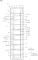
- FIG. 1 is a front view of an energy storage system according to a first embodiment of the present disclosure
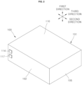
- FIG. 2 is a perspective view illustrating a first embodiment of a first battery module included in FIG. 1
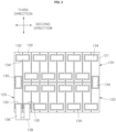
- FIG. 3 is a plan view illustrating a first embodiment of a plurality of first battery cells accommodated in a first module case illustrated in FIG. 2
- FIG. 4 is a front view illustrating the first embodiment of the plurality of first battery cells illustrated in FIG. 3
- FIG. 5 is a perspective view illustrating a first embodiment of a second battery module included in FIG. 1
- FIG. 6 is a plan view illustrating a first embodiment of a plurality of second battery cells accommodated in a second module case illustrated in FIG. 5
- FIG. 7 is a front view illustrating the first embodiment of the plurality of second battery cells illustrated in FIG. 6 .
- the first module bus bar 31 electrically connects a pair of first battery modules 100, which are disposed adjacent to each other with one second battery module 150 interposed therebetween, among the plurality of first battery modules 100.
- the first module bus bar 31 may have a stick shape extending in the first direction.
- the second battery module 150 includes a second module case 151 in which a plurality of second battery cells 170 are accommodated.
- the second module case 151 is a substantially hexahedral-shaped member having an inner space.
- the second module case 151 may include a front surface 152 on which a second negative electrode module terminal 164 and a second positive electrode module terminal 167 may be installed.
- Each of the first battery cells 120 may include a first cell case 121, a pair of first cell terminals 130, and an electrode assembly (not shown).
- the electrode assembly may be accommodated in the first cell case 121.
- the electrode assembly may be formed by winding or stacking a stack of a first electrode plate, a separator, and a second electrode plate, which may be formed as thin plates or films.
- a winding axis may be parallel to a longitudinal direction of the case.
- the electrode assembly may be a stack type electrode assembly rather than the winding type electrode assembly, and the shape of the electrode assembly is not limited in the present disclosure.
- the electrode assembly may be a Z-stack electrode assembly in which a positive electrode plate and a negative electrode plate are inserted into both sides of a separator bent in a Z shape.
- one or more electrode assemblies may be stacked such that long side surfaces thereof are adjacent to each other and accommodated in the case. The number of electrode assemblies is not limited in the present disclosure.
- the first electrode plate may serve as a negative electrode
- the second electrode plate may serve as a positive electrode. Of course, the reverse is also possible.
- the first electrode tab of the first electrode plate and the second electrode tab of the second electrode plate are located at both side end portions of the electrode assembly described above.
- the electrode assembly may be accommodated in the case with an electrolyte.
- the first current collector and the second current collector are located by being respectively welded and connected to the first electrode tab of the first electrode plate and the second electrode tab of the second electrode plate exposed to both sides of the electrode assembly.
- the pair of first cell terminals 130 may be located at both side end portions of the cap plate in the longitudinal direction.
- the first battery cell 120 may be a prismatic-type battery cell.
- one side surface of the first cell case 121 having the pair of first cell terminals 130 protruding outward will be referred to as a cell terminal side surface.
- the plurality of first battery cells 120 may be disposed inside the first module case 101 such that the pair of first cell terminals 130 protrude upward in the first direction.
- the pair of first cell terminals 130 of each of the first battery cells 120 may be arranged in the third direction, i.e., in the front/rear direction.
- the plurality of first battery cells 120 may be arranged in a single layer in the first direction, i.e., in the vertical direction, arranged to form even-numbered columns in the second direction, i.e., in the horizontal direction, and arranged to form even-numbered rows in the third direction, i.e., in the front/rear direction.
- the first module case 101 may be formed in a substantially rectangular parallelepiped shape.
- the first module case 101 may include a lower plate 112, an upper plate 110, the front plate 102, a rear plate (not shown), and a pair of side plates 105.
- the upper plate 110 may be disposed above the lower plate 112 in the first direction.
- the lower plate 112 may be in contact with and supported by the module support 16.
- the rear plate may be disposed on the rear side of the front plate 102 in the third direction, and the pair of side plates 105 may be disposed to be spaced apart from each other in the second direction.
- the plurality of first cell bus bars 134 may electrically connect the plurality of first battery cells 120. Each of the first cell bus bars 134 may connect one first cell terminal 130 of one first battery cell 120 and one first cell terminal 130 of another first battery cell 120 adjacent to the one first battery cell 120 inside the first module case 101.
- the first cell-module bus bar 136 or 138 may electrically connect one of the plurality of first battery cells 120 and one of the first positive electrode module terminal 117 and the first negative electrode module terminal 114.
- the first cell-module bus bars 136 and 138 may be provided in a pair.
- One of the pair of first cell-module bus bars 136 and 138 may be a first type first cell-module bus bar 136 configured to electrically connect the first negative electrode module terminal 114 of the first battery module 100 and one of the pair of first cell terminals 130 of one of the plurality of first battery cells 120.
- the first type first cell-module bus bar 136 may be a stick-shaped member extending to a predetermined width and thickness and bent at least once. One side of the first type first cell-module bus bar 136 in the longitudinal direction may be coupled to the first cell terminal 130 by a method such as welding.
- the first negative electrode module terminal 114 and the first positive electrode module terminal 117 may be installed on the front plate 102 to pass through the front plate 102 in a thickness direction, i.e., in the third direction.
- An outer side surface of the first negative electrode module terminal 114 may protrude to the front side to be exposed to outside of the first module case 101, and an inner side surface of the first negative electrode module terminal 114 may protrude to the rear side in the first module case 101 so as not to be exposed.
- An end portion of the first module bus bar 31 or the first control unit bus bar 41 may be coupled to the outer side surface of the first negative electrode module terminal 114.
- a side of the first type first cell-module bus bar 136 in the longitudinal direction may be coupled to the inner side surface of the first negative electrode module terminal 114 by a method such as welding.
- the second type first cell-module bus bar 138 may be a stick-shaped member extending to a predetermined width and thickness and bent at least once. One side of the second type first cell-module bus bar 138 in the longitudinal direction may be coupled to the first cell terminal 130 by a method such as welding.
- An outer side surface of the first positive electrode module terminal 117 may protrude to the front side to be exposed to outside of the first module case 101, and an inner side surface of the first positive electrode module terminal 117 may protrude to the rear side in the first module case 101 so as not to be exposed.
- An end portion of the first module bus bar 31 or the third module bus bar 36 may be coupled to the outer side surface of the first positive electrode module terminal 117.
- a side of the second type first cell-module bus bar 138 in the longitudinal direction may be coupled to the inner side surface of the first positive electrode module terminal 117 by a method such as welding.
- Each of the second battery modules 150 may include the plurality of second battery cells 170, a plurality of second cell bus bars 184, and a pair of second cell-module bus bars 186 and 188, which are accommodated in the second module case 151.
- Each of the second battery cells 170 may include a second cell case 171, a pair of second cell terminals 180, and an electrode assembly (not shown).
- the second cell case 171, the pair of second cell terminals 180, and the electrode assembly have the same configuration as the first cell case 121, the pair of first cell terminals 130, and the electrode assembly included in the first battery cell 120.
- the plurality of second battery cells 170 may be disposed inside the second module case 151 such that the pair of second cell terminals 180 protrude upward in the first direction.
- the pair of second cell terminals 180 of each of the second battery cells 170 may be arranged in the third direction, i.e., in the front/rear direction.
- the plurality of second battery cells 170 may be arranged in a single layer in the first direction, i.e., in the vertical direction, arranged to form even-numbered columns in the second direction, i.e., in the horizontal direction, and arranged to form even-numbered rows in the third direction, i.e., in the front/rear direction.
- the second module case 151 may be formed in a substantially rectangular parallelepiped shape.
- the second module case 151 may include a lower plate 162, an upper plate 160, a front plate 152, a rear plate (not shown), and a pair of side plates 155.
- the upper plate 160 may be disposed above the lower plate 162 in the first direction.
- the lower plate 162 may be in contact with and supported by the module support 16.
- the rear plate may be disposed on the rear side of the front plate 152 in the third direction, and the pair of side plates 155 may be spaced apart from each other in the second direction.
- the plurality of second cell bus bars 184 may electrically connect the plurality of second battery cells 170.
- Each of the second cell bus bars 184 may connect one second cell terminal 180 of one second battery cell 170 and one second cell terminal 180 of another second battery cell 170 adjacent to the one second battery cell 170 inside the second module case 151.
- the second cell-module bus bar 186 or 188 may electrically connect one of the plurality of second battery cells 170 and one of the second positive electrode module terminal 167 and the second negative electrode module terminal 164.
- the first type second cell-module bus bar 186 may be a stick-shaped member extending to a predetermined width and thickness and bent at least once. One side of the first type second cell-module bus bar 186 in the longitudinal direction may be coupled to the second cell terminal 180 by a method such as welding.
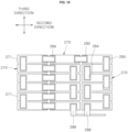
- a plurality of first battery cells 220, a plurality of first cell bus bars 234, and a pair of first cell-module bus bars 236 and 238 illustrated in FIGS. 8 and 9 may be accommodated in the first module case 101 in place of the plurality of first battery cells 120, the plurality of first cell bus bars 134, and the pair of first cell-module bus bars 136 and 138 illustrated in the first embodiment depicted in FIGS. 3 and 4 .
- the plurality of second cell bus bars 284 may electrically connect the plurality of second battery cells 270.
- Each of the second cell bus bars 284 may connect one second cell terminal 280 of one second battery cell 270 and one second cell terminal 280 of another second battery cell 270 that is adjacent to the one second battery cell 270 inside the second module case 151.
- the second cell-module bus bar 286 or 288 may electrically connect one of the plurality of second battery cells 270 and one of the second positive electrode module terminal 167 and the second negative electrode module terminal 164.
- the second cell-module bus bars 286 and 288 may be provided in a pair.
- One of the pair of second cell-module bus bars 286 and 288 may be a first type second cell-module bus bar 286 configured to electrically connect the second negative electrode module terminal 164 of the second battery module 150 and one of the pair of second cell terminals 280 of one of the plurality of second battery cells 270.
- the end portion of the second module bus bar 33 or the third module bus bar 36 may be coupled to the outer side surface of the second negative electrode module terminal 164.
- a side of the first type second cell-module bus bar 286 in the longitudinal direction may be coupled to the inner side surface of the second negative electrode module terminal 164 by a method such as welding.
- the second type second cell-module bus bar 288 may be a stick-shaped member extending to a predetermined width and thickness and bent at least once. One side of the second type second cell-module bus bar 288 in the longitudinal direction may be coupled to the second cell terminal 280 by a method such as welding.
- the end portion of the second module bus bar 33 or the second control unit bus bar 43 may be coupled to the outer side surface of the second positive electrode module terminal 167.
- a side of the second type second cell-module bus bar 288 in the longitudinal direction may be coupled to the inner side surface of the second positive electrode module terminal 167 by a method such as welding.
- the first positive electrode module terminal 117 and the first negative electrode module terminal 114 may be disposed on the left side of the front plate 102 of the first module case 101, and the second positive electrode module terminal 167 and the second negative electrode module terminal 164 may be disposed on the right side of the front plate 152 of the second module case 151.
- a plurality of first battery modules 300 and a plurality of second battery modules 350 according to the second embodiment may be supported by the rack 11 of FIG. 1 in place of the plurality of first battery modules 100 and the plurality of second battery modules 150 according to the first embodiment,
- Each of the first battery modules 300 includes a first module case 301 in which a plurality of first battery cells 320 are accommodated.
- the first module case 301 is a substantially rectangular parallelepiped member having an inner space, and the first module case 301 may include a front plate 302 on which a first negative electrode module terminal 314 and a first positive electrode module terminal 317 may be installed.
- the first module bus bar 31 electrically connects a pair of first battery modules 300, which are disposed adjacent to each other with one second battery module 350 interposed therebetween, among the plurality of first battery modules 300.
- the first module bus bar 31 may have a stick shape extending in the first direction.
- One side of the first module bus bar 31 in the longitudinal direction may be coupled to the first positive electrode module terminal 317 belonging to one of the pair of first battery modules 300.
- the other side of the first module bus bar 31 in the longitudinal direction may be coupled to the first negative electrode module terminal 314 belonging to the other one of the pair of first battery modules 300.
- the second battery module 350 includes a second module case 351 in which a plurality of second battery cells 370 are accommodated.
- the second module case 351 is a substantially hexahedral-shaped member having an inner space.
- the second module case 351 may include a front surface 352 on which a second negative electrode module terminal 364 and a second positive electrode module terminal 367 may be installed.
- the second module bus bar 33 electrically connects a pair of second battery modules 350, which are disposed adjacent to each other with one first battery module 300 interposed therebetween, among the plurality of second battery modules 350.
- the second module bus bar 33 may have a stick shape extending in the first direction.
- One side of the second module bus bar 33 in the longitudinal direction may be coupled to the second negative electrode module terminal 364 belonging to one of the pair of second battery modules 350,.
- the other side of the second module bus bar 33 in the longitudinal direction may be coupled to the second positive electrode module terminal 367 belonging to the other one of the pair of second battery modules 350.
- the third module bus bar 36 electrically connects one of the first battery modules 300 and one of the second battery modules 350 that arranged adjacent to each other.
- One side of the third module bus bar 36 may be coupled to the first positive electrode module terminal 317 of the first battery module 300, and the other side of the third module bus bar 36 may be coupled to the second negative electrode module terminal 364 of the second battery module 350.
- one side of the third module bus bar 36 may be coupled to the first negative electrode module terminal 314 of the first battery module 300, and the other side of the third module bus bar 36 may be coupled to the second positive electrode module terminal 367 of the second battery module 350.
- the first control unit bus bar 41 electrically connects the battery control unit 20 and the first battery module 300 closest to the battery control unit 20 among the plurality of first battery modules 300.
- the second control unit bus bar 43 electrically connects the battery control unit 20 and the second battery module 350 closest to the battery control unit 20 among the plurality of second battery modules 350.
- One side of the first control unit bus bar 41 in the longitudinal direction may be coupled to the first terminal 22 of the battery control unit 20.
- the other side of the first control unit bus bar 41 in the longitudinal direction may be coupled to the first negative electrode module terminal 314 of the first battery module 300 closest to the battery control unit 20.
- One side of the second control unit bus bar 43 in the longitudinal direction may be coupled to the second terminal 24 of the battery control unit 20.
- the other side of the second control unit bus bar 43 in the longitudinal direction may be coupled to the second positive electrode module terminal 367 of the second battery module 350 closest to the battery control unit 20.
- the battery control unit 20 may be disposed outside the battery module stack S in the first direction.
- the third module bus bar 36 may connect the first battery module 300 farthest from the battery control unit 20 among the plurality of first battery modules 300 and the second battery module 350 farthest from the battery control unit 20 among the plurality of second battery modules 350.
- Each of the first battery modules 300 may include the plurality of first battery cells 320, a plurality of first cell bus bars 334, and a pair of first cell-module bus bars 336 and 338, which are accommodated in the first module case 301.
- Each of the first battery cells 320 may include a first cell case 321, a pair of first cell terminals 330, and an electrode assembly (not shown).
- the first cell case 321, the pair of first cell terminals 330, and the electrode assembly have a similar configuration as the first cell case 121, the pair of first cell terminals 130, and the electrode assembly included in the first battery cell 120 according to the first embodiment described above with reference to FIGS. 3 and 4 .
- As the first cell case 121, the pair of first cell terminals 130, and the electrode assembly have been described above, repeated descriptions will be omitted.
- Each of the first battery cells 320 may further include a first cell vent 328.
- the first cell vent 328 may be installed in a side surface of the first cell case between the pair of first cell terminals 330.
- the first cell vent 328 ruptures when high-temperature gas and flames are generated inside the first cell case 321 due to overcharge or abnormal operation Emissions such as the gas and flames from inside of the first cell case 321 may be discharged to outside of the battery cells 320 through the first cell vents 328.
- the plurality of first battery cells 320 may be disposed inside the first module case 301 such that the pair of first cell terminals 330 protrude to the front side in the third direction.
- the pair of first cell terminals 330 of each of the first battery cells 320 may be arranged in the second direction, i.e., in the horizontal direction.
- the plurality of first battery cells 320 may be arranged in an even number of layers in the first direction, i.e., in the vertical direction, arranged in the second direction, i.e., in the horizontal direction to form a plurality of columns, and arranged in the third direction, i.e., in the front/rear direction to form a single row.
- the second type first cell-module bus bar 338 may be a stick-shaped member extending a predetermined width and thickness and bent at least once. One side of the second type first cell-module bus bar 338 in the longitudinal direction may be coupled to the first cell terminal 330 by a method such as welding.
- An outer side surface of the first positive electrode module terminal 317 may protrude to the front side and be exposed to outside of the first module case 301.
- An inner side surface of the first positive electrode module terminal 317 may protrude to the rear side in the first module case 301 so as not to be exposed.
- Each of the second battery cells 370 may include a second cell vent 378.
- the second cell vent 378 may be installed in a side surface of the second cell case between the pair of second cell terminals 380.
- the second cell vent 378 ruptures when high-temperature gas and flames are generated inside the second cell case 371 due to overcharge or abnormal operation. Emissions such as the gas and flames may be discharged the inside of the second cell case 371 to outside of the second cell case 371.
- the plurality of second battery cells 370 may be disposed inside the second module case 351 such that the pair of second cell terminals 380 protrude to the front side in the third direction.
- the pair of second cell terminals 380 of each of the second battery cells 370 may be arranged in the second direction, i.e., in the horizontal direction.
- the second module case 351 may be formed in a substantially rectangular parallelepiped shape.
- the second module case 351 may include a lower plate 362, an upper plate 360, a front plate 352, a rear plate (not shown), and a pair of side plates 355.
- the upper plate 360 may be disposed above the lower plate 362 in the first direction.
- the lower plate 362 may be in contact with and supported by the module support 16.
- the rear plate may be disposed on the rear side of the front plate 352 in the third direction, and the pair of side plates 355 may be spaced apart from each other in the second direction.
- the plurality of second cell bus bars 384 may electrically connect the plurality of second battery cells 370.
- Each of the second cell bus bars 384 may connect one second cell terminal 380 of one second battery cell 370 and one second cell terminal 380 of another second battery cell 370 that is adjacent to the one second battery cell 370 inside the second module case 351.
- the second negative electrode module terminal 364 and the second positive electrode module terminal 367 may be installed on the front plate 352 and pass through the front plate 352 in the thickness direction, i.e., in the third direction.
- An outer side surface of the second negative electrode module terminal 364 may protrude to the front side and exposed to outside of the second module case 351.
- An inner side surface of the second negative electrode module terminal 364 may protrude to the rear side in the second module case 351 so as not to be exposed.
- the end portion of the second module bus bar 33 or the third module bus bar 36 may be coupled to the outer side surface of the second negative electrode module terminal 364.
- a side of the first type second cell-module bus bar 386 in the longitudinal direction may be coupled to the inner side surface of the second negative electrode module terminal 364 by a method such as welding.
- the other one of the pair of second cell-module bus bars 386 and 388 may be a second type second cell-module bus bar 388 configured to electrically connect the second positive electrode module terminal 367 of the second battery module 350 and one of the pair of second cell terminals 380 of one of the plurality of second battery cells 370.
- the second type second cell-module bus bar 388 may be a stick-shaped member extending a predetermined width and thickness and bent at least once.
- One side of the second type second cell-module bus bar 388 in the longitudinal direction may be coupled to the second cell terminal 380 by a method such as welding.
- An outer side surface of the second positive electrode module terminal 367 may protrude to the front side and exposed to the outside of the second module case 351.
- An inner side surface of the second positive electrode module terminal 367 may protrude to the rear side in the second module case 351 so as not to be exposed.
- the end portion of the second module bus bar 33 or the second control unit bus bar 43 may be coupled to the outer side surface of the second positive electrode module terminal 367.
- a side of the second type second cell-module bus bar 388 in the longitudinal direction may be coupled to the inner side surface of the second positive electrode module terminal 367 by a method such as welding.
- the second module case 351 may include a second module vent 369 that opens in the second direction or in the third direction.
- a plurality of second module vents 369 each facing one of the second cell vents 378 of the second battery cells 370 are formed in the second module case 351.
- the number of second module vents 369 may correspond one-to-one to the number of second cell vents 378.
- the plurality of second module vents 369 may be formed in the front plate 352 of the second module case 351.
- the second module vents 369 may be through holes passing through the front plate 352 in the thickness direction.
- high-temperature emissions such as high-temperature gas and flames are discharged from the second cell vent 378 of the corresponding battery cell 370.
- the high-temperature emissions discharged from the second cell vent 378 may be discharged to outside of the second module case 351 through the second module vent 369 facing the second cell vent 378 without diffusing in the inside of the second module case 351.
- the first positive electrode module terminal 317 and the first negative electrode module terminal 314 of the first battery module 300 may be disposed on one side of the first battery module 300 in the second direction crossing the first direction.
- the second positive electrode module terminal 367 and the second negative electrode module terminal 364 of the second battery module 350 may be disposed on the other side of the second battery module 350 in the second direction.
- the first positive electrode module terminal 317 and the first negative electrode module terminal 314 may be disposed on the left side of the front plate 302 of the first module case 301,.
- the second positive electrode module terminal 367 and the second negative electrode module terminal 364 may be disposed on the right side of the front plate 352 of the second module case 351.
- the first battery module 300 in which the first module case 301 is rotated 180° such that one side surface and the other side surface of the first module case 301 spaced apart from each other in the first direction are reversed from each other, may be the same as the second battery module 350.
- the first battery module 300 when the first battery module 300 is rotated 180° around a rotation axis parallel to the second direction so that the upper plate 310 and the lower plate 312 are reversed to each other, the first battery module 300 may become the second battery module 350.
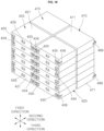
- FIG. 16 is a front view illustrating an energy storage system according to a second embodiment of the present disclosure
- FIG. 17 is a perspective view illustrating one embodiment of a battery module included in FIG. 16
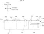
- FIG. 18 is a perspective view illustrating one example of a plurality of first battery cells and a plurality of second battery cells accommodated in a module case illustrated in FIG. 17 when viewed from one side
- FIG. 19 is a perspective view illustrating the plurality of first battery cells and the plurality of second battery cells of FIG. 18 when viewed from the opposite side to that of FIG. 18 .
- the first module bus bar 81 electrically connects the first module terminal 414 (or 417) of one battery module 400 among the plurality of battery modules 400 and the first module terminal 417 (or 414) of another battery module 400 adjacent to the one battery module 400.
- the first module bus bar 81 may have a stick shape extending in the first direction.
- One side of the first module bus bar 81 in the longitudinal direction may be coupled to the first positive electrode module terminal 417 belonging to one of the pair of battery modules 400 by a method such as welding.
- the other side of the first module bus bar 81 in the longitudinal direction may be coupled to the first negative electrode module terminal 414 belonging to the other one of the pair of battery modules 400 by a method such as welding.
- the second module bus bar 83 electrically connects the second module terminal 415 (or 418) of one battery module 400 among the plurality of battery modules 400 and the second module terminal 418 (or 415) of another battery module 400 adjacent to the one battery module 400.
- the second module bus bar 83 may have a stick shape extending in the first direction.
- One side of the second module bus bar 83 in the longitudinal direction may be coupled to the second negative electrode module terminal 415 belonging to one of the pair of battery modules 400 by a method such as welding.
- the other side of the second module bus bar 83 in the longitudinal direction may be coupled to the second positive electrode module terminal 418 belonging to the other one of the pair of battery modules 400 by a method such as welding.
- the third module bus bar 86 electrically connects the first module terminal 417 (or 414) and the second module terminal 415 (or 418) of one battery module 400 among the plurality of battery modules 400.
- One third module bus bar 86 may be provided.
- One side of the third module bus bar 86 may be coupled to a first module terminal, which is one of the first positive electrode module terminal 417 and the first negative electrode module terminal 414, of one battery module 400.
- the other side of the third module bus bar 86 may be coupled to a second module terminal of the second positive electrode module terminal 418 and the second negative electrode module terminal 415 of the one battery module 400 that a polarity opposite to a polarity of the first module terminal 414 or 417 coupled to the one side.
- the third module bus bar 86 may have a stack shape extending in a second direction.
- One side of the third module bus bar 86 is coupled to the first positive electrode module terminal 417 of one battery module 400 by a method such as welding.
- the other side of the third module bus bar 86 may be coupled to the second negative electrode module terminal 415 of the one battery module 400 by a method such as welding. However, unlike the configuration shown in FIG. 16 , one side of the third module bus bar 86 may be coupled to the first negative electrode module terminal 414 of the battery module 400, and the other side of the third module bus bar 86 may be coupled to the second positive electrode module terminal 418 of the battery module 400.
- the energy storage system 50 may further include a battery control unit 70 configured to control the charging and discharging of the plurality of battery modules 400.
- the energy storage system 50 may also include a first control unit bus bar 91 configured to electrically connect the battery control unit 70 and the first module terminal 414 (or 417) of the battery module 400 closest to the battery control unit 70 among the plurality of battery modules 400.
- the energy storage system 50 may also include a second control unit bus bar 93 configured to electrically connect the battery control unit 70 and the second module terminal 415 (or 418) of the battery module 400 closest to the battery control unit 70 among the plurality of battery modules 400.
- the first control unit bus bar 91 and the second control unit bus bar 93 may each have a stick shape extending in the first direction.
- One side of the first control unit bus bar 91 in the longitudinal direction may be coupled to a first terminal 72 of the battery control unit 70 by a method such as welding.
- the other side of the first control unit bus bar 91 in the longitudinal direction may be coupled to the first negative electrode module terminal 414 of the battery module 400 that is closest to the battery control unit 70 by a method such as welding.
- One side of the second control unit bus bar 93 in the longitudinal direction may be coupled to a second terminal 74 of the battery control unit 70 by a method such as welding.
- the other side of the second control unit bus bar 93 in the longitudinal direction may be coupled to the second positive electrode module terminal 418 of the battery module 400 that is closest to the battery control unit 70 by a method such as welding.
- the battery control unit 70 may be connected to the battery module 400, which is disposed at one end side of the plurality of battery modules 400 in the first direction, by the first control unit bus bar 91 and the second control unit bus bar 93.
- the third module bus bar 86 may connect the first module terminals 417 (or 414) and the second module terminal 418 (or 415) of the battery module 400 disposed at the other end side of the plurality of battery modules 400 in the first direction.
- the energy storage system 50 may further include a rack 51 supporting the plurality of battery modules 400 and the battery control unit 70.
- the rack 51 may include a rack frame 53, a plurality of module supports 56, and a control unit support 58.
- the rack frame 53 may extend in the first direction and may be provided as four rack frames 53.
- the four rack frames 53 may be be spaced apart from each other.
- the plurality of module supports 56 may be fixed to the rack frame 53 and may support the plurality of battery modules 400.
- the plurality of module supports 56 may be spaced apart from each other in the first direction at regular intervals. Accordingly, a plurality of layers are formed in the rack 51 in the first direction.
- a layer height between the pair of module supports 56 in the first direction may be greater than the size of a width of the battery module 400 in the first direction.
- the control unit support 58 supports the battery control unit 70.
- the control unit support 58 may be located higher than the module support 56 on the uppermost layer among the plurality of module supports 56.
- the first direction may be a vertical direction
- the second direction may be a horizontal direction orthogonal to the first direction
- a third direction may be a front/rear direction orthogonal to the first direction and the second direction.
- Each of the first battery cells 420 may include a first cell case 421, a pair of first cell terminals 430, and an electrode assembly (not shown).
- the first cell case 421, the pair of first cell terminals 430, and the electrode assembly respectively have a similar configuration as the first cell case 121, the pair of first cell terminals 130, and the electrode assembly included in the first battery cell 120 according to the first embodiment described with reference to FIGS. 3 and 4 .
- As the first cell case 121, the pair of first cell terminals 130, and the electrode assembly have been described above, repeated descriptions will be omitted.
- Each of the first battery cells 420 may further include a first cell vent 428.
- the first cell vent 428 may be installed in a side surface of the first cell case between the pair of first cell terminals 430.
- the first cell vent 428 ruptures when high-temperature gas and flames are generated inside the first cell case 421 due to overcharge or abnormal operation. Emissions such as the gas and flames from the inside of the first cell case 421 may be discharged through the ruptured first cell vent 428 to the outside to outside of the battery cell 430.
- the plurality of first battery cells 420 may be disposed inside the module case 401 such that the pair of first cell terminals 430 protrude to one side in the second direction.
- the pair of first cell terminals 430 may be disposed to protrude to the left side.
- the pair of first cell terminals 430 of each of the first battery cells 420 may be arranged in the third direction, i.e., in the front/rear direction.
- the module case 401 may be formed in a substantially rectangular parallelepiped shape.
- the module case 401 may include a lower plate 412, an upper plate 410, the front plate 402, a rear plate (not shown), and a pair of side plates 405.
- the upper plate 410 may be disposed above the lower plate 412 in the first direction.
- the lower plate 412 may be in contact with and supported by the module support 56.
- the rear plate (not shown) may be disposed on the rear side of the front plate 402 in the third direction, and the pair of side plates 405 may be spaced apart from each other in the second direction.
- the plurality of first cell bus bars 434 may electrically connect the plurality of first battery cells 420.
- Each of the first cell bus bars 434 may connect one first cell terminal 430 of one first battery cell 420 and one first cell terminal 430 of another first battery cell 420 adjacent to the one first battery cell 420 inside the module case 401.
- the first cell-module bus bar 436 or 438 may electrically connect one of the plurality of first battery cells 420 and one of the first positive electrode module terminal 417 and the first negative electrode module terminal 414.
- the first cell-module bus bars 436 and 438 may be provided in a pair.
- One of the pair of first cell-module bus bars 436 and 438 may be a first type first cell-module bus bar 436 configured to electrically connect the first negative electrode module terminal 414 of the battery module 400 and one of the pair of first cell terminals 430 of one of the plurality of first battery cells 420.
- the first type first cell-module bus bar 436 may be a stick-shaped member extending a predetermined width and thickness and bent at least once.
- One side of the first type first cell-module bus bar 436 in the longitudinal direction may be coupled to the first cell terminal 430 by a method such as welding.
- An outer side surface of the first positive electrode module terminal 417 may protrude to the front side to be exposed to the outside of the module case 401.
- An inner side surface of the first positive electrode module terminal 417 may protrude to the rear side in the module case 401 so as not to be exposed.
- An end portion of the first module bus bar 81 or the third module bus bar 86 may be coupled to the outer side surface of the first positive electrode module terminal 417.
- the other side of the second type first cell-module bus bar 438 in the longitudinal direction may be coupled to the inner side surface of the first positive electrode module terminal 417 by a method such as welding.
- Each of the second battery cells 470 may include a second cell case 471, a pair of second cell terminals 480, and an electrode assembly (not shown).
- the second cell case 471, the pair of second cell terminals 480, and the electrode assembly respectively have a similar configuration as the first cell case 121, the pair of first cell terminals 130, and the electrode assembly included in the first battery cell 120 according to the first embodiment described above with reference to FIGS. 3 and 4 .
- Each of the second battery cells 470 may further include a second cell vent 478.
- the second cell vent 478 may be installed in a side surface of the second cell case between the pair of second cell terminals 480.
- the second cell vent 478 ruptures when high-temperature gas and flames are generated inside the second cell case 471 due to overcharge or abnormal operation. Emissions such as the gas and flames from the inside of the second cell case 471 may be discharged through the ruptured second cell vent 470 to outside of the second battery cell 470.
- the plurality of second battery cells 470 may be disposed inside the module case 401 such that the pair of second cell terminals 480 protrude to one side in the second direction.
- the pair of second cell terminals 480 may be disposed to protrude to the right side.
- the pair of second cell terminals 480 of each of the second battery cells 470 may be arranged in the third direction, i.e., in the front/rear direction.
- the plurality of second battery cells 470 may be arranged in an even number of layers in the first direction, i.e., in the vertical direction, arranged in the second direction, i.e., in the horizontal direction to form a single row, and arranged in the third direction, i.e., in the front/rear direction to form a plurality of columns.
- the plurality of first battery cells 420 and the plurality of second battery cells 470 may be arranged to be opposite to each other in the horizontal direction in the module case 401.
- the second cell-module bus bar 486 or 488 may electrically connect one of the plurality of second battery cells 470 and one of the second positive electrode module terminal 418 and the second negative electrode module terminal 415.
- the second cell-module bus bars 486 and 488 may be provided in a pair.
- One of the pair of second cell-module bus bars 486 and 488 may be a first type second cell-module bus bar 486 configured to electrically connect the second negative electrode module terminal 415 of the battery module 400 and one of the pair of second cell terminals 480 of one of the plurality of second battery cells 470.
- the first type second cell-module bus bar 486 may be a stick-shaped member extending a predetermined width and thickness and bent at least once. One side of the first type second cell-module bus bar 486 in the longitudinal direction may be coupled to the second cell terminal 480 by a method such as welding.
- An end portion of the second module bus bar 83 or the third module bus bar 86 may be coupled to the outer side surface of the second negative electrode module terminal 415.
- a side of the first type second cell-module bus bar 486 in the longitudinal direction may be coupled to the inner side surface of the second negative electrode module terminal 415 by a method such as welding.
- the module case 401 may include a module vent 419 that opens in the second direction or in the third direction.
- a plurality of module vents 419 facing the first cell vents 428 of the first battery cells 420 and the second cell vents 478 of the second battery cells 470 are formed in the module case 401.
- the number of module vents 419 may correspond one-to-one to the number of first cell vents 428 and the second cell vents 478.
- the plurality of module vents 419 may be formed on both side plates 405 of the module case 401.
- the module vent 419 may be a through hole passing through the side plate 405 in the thickness direction.
Landscapes
- Chemical & Material Sciences (AREA)
- Chemical Kinetics & Catalysis (AREA)
- Electrochemistry (AREA)
- General Chemical & Material Sciences (AREA)
- Engineering & Computer Science (AREA)
- Manufacturing & Machinery (AREA)
- Microelectronics & Electronic Packaging (AREA)
- Connection Of Batteries Or Terminals (AREA)
Applications Claiming Priority (1)
| Application Number | Priority Date | Filing Date | Title |
|---|---|---|---|
| KR1020240001533A KR20250106925A (ko) | 2024-01-04 | 2024-01-04 | 에너지 저장 장치 |
Publications (2)
| Publication Number | Publication Date |
|---|---|
| EP4583271A2 true EP4583271A2 (de) | 2025-07-09 |
| EP4583271A3 EP4583271A3 (de) | 2025-07-30 |
Family
ID=94128428
Family Applications (1)
| Application Number | Title | Priority Date | Filing Date |
|---|---|---|---|
| EP24223336.9A Pending EP4583271A3 (de) | 2024-01-04 | 2024-12-27 | Energiespeichersystem |
Country Status (3)
| Country | Link |
|---|---|
| US (1) | US20260121239A1 (de) |
| EP (1) | EP4583271A3 (de) |
| KR (1) | KR20250106925A (de) |
Family Cites Families (3)
| Publication number | Priority date | Publication date | Assignee | Title |
|---|---|---|---|---|
| KR102519443B1 (ko) * | 2017-12-27 | 2023-04-07 | 삼성에스디아이 주식회사 | 배터리 팩 |
| KR102743778B1 (ko) * | 2021-11-02 | 2024-12-18 | 주식회사 블루시그마 | 망 형태의 버스 바 연결 구조를 갖는 배터리 팩 |
| CN216958413U (zh) * | 2021-11-29 | 2022-07-12 | 江苏正力新能电池技术有限公司 | 一种电池模组和电池包 |
-
2024
- 2024-01-04 KR KR1020240001533A patent/KR20250106925A/ko active Pending
- 2024-12-27 EP EP24223336.9A patent/EP4583271A3/de active Pending
-
2025
- 2025-01-03 US US19/008,946 patent/US20260121239A1/en active Pending
Also Published As
| Publication number | Publication date |
|---|---|
| US20260121239A1 (en) | 2026-04-30 |
| KR20250106925A (ko) | 2025-07-11 |
| EP4583271A3 (de) | 2025-07-30 |
Similar Documents
| Publication | Publication Date | Title |
|---|---|---|
| KR100560498B1 (ko) | 이차 전지와 이를 이용한 전지 모듈 | |
| CN103918106B (zh) | 具有优良电极突片连接性的电极组件、包括电极组件的电池单元和装置及制造电极组件的方法 | |
| WO2007080456A2 (en) | Electrochemical cell for hybrid electric vehicle applications | |
| EP3451434B1 (de) | Lithium-ionen-sekundärbatterie | |
| CN216850214U (zh) | 一种矩阵式软包电池及电池包 | |
| EP4583271A2 (de) | Energiespeichersystem | |
| EP4429013A1 (de) | Stapelelektrodenanordnung mit verbesserter zellkapazität | |
| KR20240099037A (ko) | 배터리 모듈 및 이를 포함하는 배터리 팩 | |
| KR102564098B1 (ko) | 하나 이상의 냉각 유체 흐름 오리피스를 포함하는 가요성 패키징을 갖는 전기화학 축전지, 특히 금속-이온 축전지, 연관된 모듈 및 제조 방법 | |
| US20260031449A1 (en) | Cap assembly and secondary battery including same | |
| KR20220074498A (ko) | 전극 조립체 및 이를 포함하는 이차전지 | |
| US20260106258A1 (en) | Battery module and battery pack including the same | |
| US20260005387A1 (en) | Battery cells with gas guiding plate, frame, or springs arranged between battery stacks or rolls | |
| EP4618249A1 (de) | Batteriemodul | |
| US20250149621A1 (en) | Electrode Assembly Support Device | |
| US20260045624A1 (en) | Battery module | |
| US20260011864A1 (en) | Battery module and battery pack | |
| US20260038965A1 (en) | Battery cell, battery, and electric device | |
| EP4621975A1 (de) | Batteriemodul und verfahren zur herstellung des batteriemoduls | |
| JP7439034B2 (ja) | 電池スタック | |
| EP4683020A1 (de) | Sekundärbatterie mit gehäuse mit vertieftem abschnitt und herstellungsverfahren dafür | |
| US20240162525A1 (en) | Electrode assembly, secondary battery, battery pack, and electrical apparatus | |
| EP4654337A1 (de) | Batteriemodul | |
| US20260066505A1 (en) | Cap assembly and secondary battery including same | |
| US20260121253A1 (en) | Secondary battery |
Legal Events
| Date | Code | Title | Description |
|---|---|---|---|
| PUAI | Public reference made under article 153(3) epc to a published international application that has entered the european phase |
Free format text: ORIGINAL CODE: 0009012 |
|
| STAA | Information on the status of an ep patent application or granted ep patent |
Free format text: STATUS: REQUEST FOR EXAMINATION WAS MADE |
|
| PUAL | Search report despatched |
Free format text: ORIGINAL CODE: 0009013 |
|
| 17P | Request for examination filed |
Effective date: 20241227 |
|
| AK | Designated contracting states |
Kind code of ref document: A2 Designated state(s): AL AT BE BG CH CY CZ DE DK EE ES FI FR GB GR HR HU IE IS IT LI LT LU LV MC ME MK MT NL NO PL PT RO RS SE SI SK SM TR |
|
| AK | Designated contracting states |
Kind code of ref document: A3 Designated state(s): AL AT BE BG CH CY CZ DE DK EE ES FI FR GB GR HR HU IE IS IT LI LT LU LV MC ME MK MT NL NO PL PT RO RS SE SI SK SM TR |
|
| RIC1 | Information provided on ipc code assigned before grant |
Ipc: H01M 50/209 20210101AFI20250626BHEP Ipc: H01M 50/296 20210101ALI20250626BHEP Ipc: H01M 50/502 20210101ALI20250626BHEP Ipc: H01M 50/51 20210101ALI20250626BHEP |