EP4583252A1 - Battery module having heating function - Google Patents
Battery module having heating function Download PDFInfo
- Publication number
- EP4583252A1 EP4583252A1 EP24863081.6A EP24863081A EP4583252A1 EP 4583252 A1 EP4583252 A1 EP 4583252A1 EP 24863081 A EP24863081 A EP 24863081A EP 4583252 A1 EP4583252 A1 EP 4583252A1
- Authority
- EP
- European Patent Office
- Prior art keywords
- battery module
- heat conduction
- module according
- frame
- pressing member
- Prior art date
- Legal status (The legal status is an assumption and is not a legal conclusion. Google has not performed a legal analysis and makes no representation as to the accuracy of the status listed.)
- Pending
Links
Images



Classifications
-
- H—ELECTRICITY
- H01—ELECTRIC ELEMENTS
- H01M—PROCESSES OR MEANS, e.g. BATTERIES, FOR THE DIRECT CONVERSION OF CHEMICAL ENERGY INTO ELECTRICAL ENERGY
- H01M50/00—Constructional details or processes of manufacture of the non-active parts of electrochemical cells other than fuel cells, e.g. hybrid cells
- H01M50/20—Mountings; Secondary casings or frames; Racks, modules or packs; Suspension devices; Shock absorbers; Transport or carrying devices; Holders
- H01M50/204—Racks, modules or packs for multiple batteries or multiple cells
- H01M50/207—Racks, modules or packs for multiple batteries or multiple cells characterised by their shape
- H01M50/213—Racks, modules or packs for multiple batteries or multiple cells characterised by their shape adapted for cells having curved cross-section, e.g. round or elliptic
-
- H—ELECTRICITY
- H01—ELECTRIC ELEMENTS
- H01M—PROCESSES OR MEANS, e.g. BATTERIES, FOR THE DIRECT CONVERSION OF CHEMICAL ENERGY INTO ELECTRICAL ENERGY
- H01M10/00—Secondary cells; Manufacture thereof
- H01M10/42—Methods or arrangements for servicing or maintenance of secondary cells or secondary half-cells
- H01M10/48—Accumulators combined with arrangements for measuring, testing or indicating the condition of cells, e.g. the level or density of the electrolyte
- H01M10/486—Accumulators combined with arrangements for measuring, testing or indicating the condition of cells, e.g. the level or density of the electrolyte for measuring temperature
-
- H—ELECTRICITY
- H01—ELECTRIC ELEMENTS
- H01M—PROCESSES OR MEANS, e.g. BATTERIES, FOR THE DIRECT CONVERSION OF CHEMICAL ENERGY INTO ELECTRICAL ENERGY
- H01M10/00—Secondary cells; Manufacture thereof
- H01M10/60—Heating or cooling; Temperature control
- H01M10/61—Types of temperature control
- H01M10/613—Cooling or keeping cold
-
- H—ELECTRICITY
- H01—ELECTRIC ELEMENTS
- H01M—PROCESSES OR MEANS, e.g. BATTERIES, FOR THE DIRECT CONVERSION OF CHEMICAL ENERGY INTO ELECTRICAL ENERGY
- H01M10/00—Secondary cells; Manufacture thereof
- H01M10/60—Heating or cooling; Temperature control
- H01M10/61—Types of temperature control
- H01M10/615—Heating or keeping warm
-
- H—ELECTRICITY
- H01—ELECTRIC ELEMENTS
- H01M—PROCESSES OR MEANS, e.g. BATTERIES, FOR THE DIRECT CONVERSION OF CHEMICAL ENERGY INTO ELECTRICAL ENERGY
- H01M10/00—Secondary cells; Manufacture thereof
- H01M10/60—Heating or cooling; Temperature control
- H01M10/62—Heating or cooling; Temperature control specially adapted for specific applications
- H01M10/623—Portable devices, e.g. mobile telephones, cameras or pacemakers
-
- H—ELECTRICITY
- H01—ELECTRIC ELEMENTS
- H01M—PROCESSES OR MEANS, e.g. BATTERIES, FOR THE DIRECT CONVERSION OF CHEMICAL ENERGY INTO ELECTRICAL ENERGY
- H01M10/00—Secondary cells; Manufacture thereof
- H01M10/60—Heating or cooling; Temperature control
- H01M10/62—Heating or cooling; Temperature control specially adapted for specific applications
- H01M10/625—Vehicles
-
- H—ELECTRICITY
- H01—ELECTRIC ELEMENTS
- H01M—PROCESSES OR MEANS, e.g. BATTERIES, FOR THE DIRECT CONVERSION OF CHEMICAL ENERGY INTO ELECTRICAL ENERGY
- H01M10/00—Secondary cells; Manufacture thereof
- H01M10/60—Heating or cooling; Temperature control
- H01M10/63—Control systems
- H01M10/637—Control systems characterised by the use of reversible temperature-sensitive devices, e.g. NTC, PTC or bimetal devices; characterised by control of the internal current flowing through the cells, e.g. by switching
-
- H—ELECTRICITY
- H01—ELECTRIC ELEMENTS
- H01M—PROCESSES OR MEANS, e.g. BATTERIES, FOR THE DIRECT CONVERSION OF CHEMICAL ENERGY INTO ELECTRICAL ENERGY
- H01M10/00—Secondary cells; Manufacture thereof
- H01M10/60—Heating or cooling; Temperature control
- H01M10/64—Heating or cooling; Temperature control characterised by the shape of the cells
- H01M10/643—Cylindrical cells
-
- H—ELECTRICITY
- H01—ELECTRIC ELEMENTS
- H01M—PROCESSES OR MEANS, e.g. BATTERIES, FOR THE DIRECT CONVERSION OF CHEMICAL ENERGY INTO ELECTRICAL ENERGY
- H01M10/00—Secondary cells; Manufacture thereof
- H01M10/60—Heating or cooling; Temperature control
- H01M10/65—Means for temperature control structurally associated with the cells
- H01M10/653—Means for temperature control structurally associated with the cells characterised by electrically insulating or thermally conductive materials
-
- H—ELECTRICITY
- H01—ELECTRIC ELEMENTS
- H01M—PROCESSES OR MEANS, e.g. BATTERIES, FOR THE DIRECT CONVERSION OF CHEMICAL ENERGY INTO ELECTRICAL ENERGY
- H01M10/00—Secondary cells; Manufacture thereof
- H01M10/60—Heating or cooling; Temperature control
- H01M10/65—Means for temperature control structurally associated with the cells
- H01M10/655—Solid structures for heat exchange or heat conduction
- H01M10/6551—Surfaces specially adapted for heat dissipation or radiation, e.g. fins or coatings
-
- H—ELECTRICITY
- H01—ELECTRIC ELEMENTS
- H01M—PROCESSES OR MEANS, e.g. BATTERIES, FOR THE DIRECT CONVERSION OF CHEMICAL ENERGY INTO ELECTRICAL ENERGY
- H01M10/00—Secondary cells; Manufacture thereof
- H01M10/60—Heating or cooling; Temperature control
- H01M10/65—Means for temperature control structurally associated with the cells
- H01M10/655—Solid structures for heat exchange or heat conduction
- H01M10/6554—Rods or plates
-
- H—ELECTRICITY
- H01—ELECTRIC ELEMENTS
- H01M—PROCESSES OR MEANS, e.g. BATTERIES, FOR THE DIRECT CONVERSION OF CHEMICAL ENERGY INTO ELECTRICAL ENERGY
- H01M10/00—Secondary cells; Manufacture thereof
- H01M10/60—Heating or cooling; Temperature control
- H01M10/65—Means for temperature control structurally associated with the cells
- H01M10/656—Means for temperature control structurally associated with the cells characterised by the type of heat-exchange fluid
- H01M10/6567—Liquids
-
- H—ELECTRICITY
- H01—ELECTRIC ELEMENTS
- H01M—PROCESSES OR MEANS, e.g. BATTERIES, FOR THE DIRECT CONVERSION OF CHEMICAL ENERGY INTO ELECTRICAL ENERGY
- H01M50/00—Constructional details or processes of manufacture of the non-active parts of electrochemical cells other than fuel cells, e.g. hybrid cells
- H01M50/20—Mountings; Secondary casings or frames; Racks, modules or packs; Suspension devices; Shock absorbers; Transport or carrying devices; Holders
- H01M50/289—Mountings; Secondary casings or frames; Racks, modules or packs; Suspension devices; Shock absorbers; Transport or carrying devices; Holders characterised by spacing elements or positioning means within frames, racks or packs
-
- H—ELECTRICITY
- H01—ELECTRIC ELEMENTS
- H01M—PROCESSES OR MEANS, e.g. BATTERIES, FOR THE DIRECT CONVERSION OF CHEMICAL ENERGY INTO ELECTRICAL ENERGY
- H01M10/00—Secondary cells; Manufacture thereof
- H01M10/42—Methods or arrangements for servicing or maintenance of secondary cells or secondary half-cells
- H01M10/425—Structural combination with electronic components, e.g. electronic circuits integrated to the outside of the casing
- H01M2010/4271—Battery management systems including electronic circuits, e.g. control of current or voltage to keep battery in healthy state, cell balancing
-
- Y—GENERAL TAGGING OF NEW TECHNOLOGICAL DEVELOPMENTS; GENERAL TAGGING OF CROSS-SECTIONAL TECHNOLOGIES SPANNING OVER SEVERAL SECTIONS OF THE IPC; TECHNICAL SUBJECTS COVERED BY FORMER USPC CROSS-REFERENCE ART COLLECTIONS [XRACs] AND DIGESTS
- Y02—TECHNOLOGIES OR APPLICATIONS FOR MITIGATION OR ADAPTATION AGAINST CLIMATE CHANGE
- Y02E—REDUCTION OF GREENHOUSE GAS [GHG] EMISSIONS, RELATED TO ENERGY GENERATION, TRANSMISSION OR DISTRIBUTION
- Y02E60/00—Enabling technologies; Technologies with a potential or indirect contribution to GHG emissions mitigation
- Y02E60/10—Energy storage using batteries
Definitions
- the present invention relates to a battery module with a heating function, and more particularly to a battery module with a heating function capable of preventing the battery module from being unable to be charged at low temperatures.
- the conventional battery module does not have a separate temperature control function for measuring and regulating the temperature of the battery cells 10.
- the heat conduction pad (400) may have a recess (410) configured to receive a part of each cylindrical battery cell (100) at the position corresponding to the plurality of cylindrical battery cell (100).
- the plurality of holes (310) may be formed at the positions corresponding to the recesses (410).
- the operation unit (520) may include a vertical portion (521) extending inwardly of the receiving frame (500), the vertical portion having a predetermined space portion, a indented portion (522) located at an end of the vertical portion (521), the indented portion being indented in the direction toward the space portion of the vertical portion (521), and a bar-shaped pressing member (523) configured such that one side of the pressing member is in tight contact with the indented portion (522) and the other side of the pressing member protrudes outside of the receiving frame (500).
- the pressing member (523) may be provided at an outwardly protruding part thereof with an operation control portion (524) configured to control movement of the pressing member (523).
- the operation unit may further include a switch cap portion (525) configured to cover the outwardly protruding part of the pressing member.
- the heat conduction unit (530) may be located such that one side of the heat conduction unit is in tight contact with the heat conduction pad (400) through the plurality of holes (310).
- the heat conduction unit (530) may include a tight contact portion (531) in tight contact with the heat conduction pad (400) and a plurality of extension fin portions (532) extending from the tight contact portion (531) in the direction toward the inside of the receiving frame.
- a thermally conductive adhesive member may be applied between the heat conduction pad (400) and the tight contact portion (531).
- the receiving frame (500) may be provided on an outer surface having a display unit (600) configured to display when the operation unit (520) needs to be operated.
- the display unit (600) may be provided with a battery management system (BMS).
- BMS battery management system
- the battery management system may be connected to the operation control portion (524) via a connection portion (610), and may be connected to a temperature sensor (620) mounted in the space portion of the receiving frame (500).
- the heating solution (510) may be a supersaturated solution.
- the supersaturated solution may be a supersaturated aqueous solution of sodium acetate.
- a battery module according to the present invention has the advantage that a heating solution, which is a supersaturated solution, is provided, whereby the battery module may be heated at a low temperature to create a state in which the battery module can be charged.
- the battery module according to the present invention has the advantage that a heat conduction pad and a heat conduction unit are provided, whereby the heat generated by the heating solution may be more efficiently transferred to a cylindrical battery cell.
- the current interrupting member which is also called a current interrupt device (CID)
- CID current interrupt device
- the first frame 200 may be of a height capable of receiving about half of the cylindrical battery cell 100 when the cylindrical battery cell 100 is received in the receiving hole 210.
- the second frame 300 is configured to protect a part of the cylindrical battery cell 100 not received in the first frame 200 from external impact or the like, and may be in the shape of a hexahedron with one side open, and a hole 310 formed through the second frame 300 may be provided on the other side surface of the second frame.
- first frame 100 and the second frame 200 may be fastened and fixed to each other using a bolt in a state of being in tight contact with each other, and a fastening method is not particularly restricted as long as the first frame 100 and the second frame 200 can be fixed to each other in a state of being in tight contact with each other.
- the heat conduction pad 400 may be located inside the surface of the second frame 300 where the hole 310 is formed, and may be in the shape of a rectangular sheet.
- the heat conduction pad 400 may have a receiving recess 410 configured to receive a part of the cylindrical battery cell 100 at the position corresponding to the cylindrical battery cell 100, and the receiving recess 410 may increase the contact surface area between the heat conduction pad 400 and the cylindrical battery cell 100, thereby improving heat conduction efficiency.
- the receiving frame 500 may be formed in the shape of a hexahedron with one side open, may have a space portion having a predetermined volume, and may include a heating solution 510, an operation unit 520, and a heat conduction unit 530.
- the heating solution 510 may be received in the space portion formed by the receiving frame 500, and may be a supersaturated solution.
- the supersaturated solution has the advantage of being recyclable, as the supersaturated solution can be returned to the supersaturated solution state if heat is applied after the phase change is completed while heat is dissipated.
- the vertical portion 521 extends inwardly of the receiving frame 500 and forms the space portion.
- the indented portion 522 may be located at the extended end of the vertical portion 521 and may be formed in a indented shape in the direction toward the space portion formed by the vertical portion 521.
- each of the vertical portion 521 and the indented portion 522 may be made of an elastic material.
- the operation control portion 524 may be configured to wrap around a side surface of the pressing member 523 that protrudes outwardly of the receiving frame 500, and may be located such that one side of the operation control portion is in tight contact with the receiving frame 500.
- the operation control portion 524 may fix the pressing member 523 to restrict the movement thereof or release the fixed state thereof to allow the pressing member 523 to move according to a received signal.
- the operation control portion 524 may be in the shape of a gripper that wraps around the pressing member 523, and is not particularly restricted as long as the operation control portion has a structure capable of fixing the movement of the pressing member 523 and releasing the fixed state of the pressing member.
- the upper surface part of the switch cap portion 525 is in tight contact with the pressing member 523, whereby pressing force may be transmitted to the pressing member 523 when the upper surface part is pressed.
- a method of connecting the side surface part and the upper surface part of the switch cap portion 525 to each other is not particularly restricted as long as the pressure is transmitted to the pressing member 523 when pressed in the state of being connected to each other such that the pressing member 523 can be moved.
- the heat conduction unit 530 is configured to transfer heat generated when the heating solution 510 undergoes phase change to the cylindrical battery cell 100, and may include a tight contact portion 531 and an extension fin portion 532.
- the tight contact portion 531 is configured to transfer heat generated when the heating solution 51 undergoes phase change to the cylindrical battery cell 100, and may be located so as to be in tight contact with the heat conduction pad 400 exposed through the hole 310 of the second frame 300.
- the tight contact portion 531 may be in the form of a thin sheet, and may be formed in a horizontal sectional shape corresponding to the hole 310.
- the area of the tight contact portion 531 is less than or equal to the area of the hole 310.
- the extension fin portion 532 has the advantage of being formed in the shape of a plurality of thin pins to form a larger contact area per unit volume with the heating solution 510, thereby improving heat exchange efficiency.
- the display unit 600 is provided on an outer surface of the receiving frame 500, and may be formed in a structure in which a part of the display unit is received in the receiving frame 500 as needed.
- the display unit 600 may be provided with a battery management system (BMS).
- BMS battery management system
- the display unit 600 may display whether the battery module needs to be heated and whether the operation unit 520 needs to be operated, may be, for example, a display capable of displaying text, and may be further provided with a connection portion 610 and a temperature sensor 620.
- connection portion 610 connects the display unit 600 and the operation control portion 524 to each other such that an electrical signal can be transmitted to control the movement of the pressing member 523 through the operation control portion 524.
- the temperature sensor 620 extends from the display unit 600, measures the temperature of the heating solution 510 received in the receiving frame 500, and provides a measured value that is considered in displaying whether the operation unit 520 is to be operated on the display unit 600.
- the display unit 600 may display that the operation unit 520 needs to be operated when the temperature of the cylindrical battery cell 100 is equal to or less than the reference value and the temperature of the heating solution 510 measured through the temperature sensor 620 is low.
- FIG. 7 is a view showing the operation of an operation unit according to a preferred embodiment of the present invention.
- the operation control portion 524 holds the pressing member 523 in a fixed state when the display unit 600 displays that the operation unit does not need to be operated, as shown in FIG. 7(a) .
- the display unit 600 displays that that the operation unit needs to be operated. At this time, the operation control portion 524 releases the fixed state of the pressing member 523 such that the pressing member 523 can move.
Landscapes
- Chemical & Material Sciences (AREA)
- Chemical Kinetics & Catalysis (AREA)
- Electrochemistry (AREA)
- General Chemical & Material Sciences (AREA)
- Engineering & Computer Science (AREA)
- Manufacturing & Machinery (AREA)
- Life Sciences & Earth Sciences (AREA)
- Biophysics (AREA)
- Automation & Control Theory (AREA)
- Battery Mounting, Suspending (AREA)
- Secondary Cells (AREA)
- Primary Cells (AREA)
Abstract
Description
- This application claims the benefit of priority to
Korean Patent Application No. 2023-0118914 filed on September 7, 2023 - The present invention relates to a battery module with a heating function, and more particularly to a battery module with a heating function capable of preventing the battery module from being unable to be charged at low temperatures.
- With recent development of alternative energies due to air pollution and energy depletion caused as the result of use of fossil fuels, demand for secondary batteries capable of storing electrical energy that is produced has increased.
- Required capacities of secondary batteries used as energy sources of various kinds of electronic devices inevitably used in modern society have been increased due to an increase in usage of mobile devices, increasing complexity of the mobile devices, and development of electric vehicles. In order to satisfy demand of users, a plurality of battery cells is disposed in a small-sized device, whereas a battery module including a plurality of battery cells electrically connected to each other or a battery pack including a plurality of battery modules is used in a vehicle, etc.
- Meanwhile, secondary batteries are not charged even if electricity is supplied below a certain temperature, and it is difficult to charge small secondary batteries in winter.
-
FIG. 1 is an exploded perspective view showing a conventional battery module. As shown inFIG. 1 , the conventional battery module includes a plurality ofbattery cells 10, aterminal 20 configured to electrically connect the plurality ofbattery cells 10 to each other, aholder case 30 configured to support side surfaces of thebattery cells 10, and amodule case 40 configured to receive the aforementioned components. - The conventional battery module does not have a separate temperature control function for measuring and regulating the temperature of the
battery cells 10. - Accordingly, the conventional battery module has the problem that, when the conventional battery module is mounted in a small device, charging may not proceed in an environment with a low temperature, such as in winter, resulting in the inability to use the device in which the conventional battery module is mounted.
- (Patent Document 1)
Korean Patent Application Publication No. 2012-0054337 - The present invention has been made in view of the above problems, and it is an object of the present invention to provide a battery module assembly with a fire extinguishing function capable of extinguishing a fire in the battery module assembly when a fire occurs in a battery cell received in the battery module assembly, thereby preventing the fire in the battery module assembly from spreading to a battery module assembly adjacent thereto and a battery pack including the same.
- It is another object of the present invention to provide a battery module assembly with a fire extinguishing function capable of reliably exhausting the air in the vicinity of a battery module and further increasing space utilization and a battery pack including the same.
- It is a further object of the present invention to provide a battery module assembly with a fire extinguishing function having a structure capable of discharging heat generated by a battery module to the outside when the battery module is normally operated and a battery pack including the same.
- A battery module with a heating function according to the present invention to accomplish the above objects includes a plurality of cylindrical battery cells (100),
a first frame (200) having a receiving hole (210) configured to receive the plurality of cylindrical battery cells (100), a second frame (300) having a plurality of holes (310) incised so as to each have a predetermined area in one side surface thereof, the second frame being coupled to the first frame (200), a heat conduction pad (400) located inside the second frame (300), the heat conduction pad being configured to cover the plurality of holes (310), and a receiving frame (500) having a space portion that is configured to receive a heating solution (510) and an operation unit (520) configured to activate the heating solution (510), wherein a heat conduction unit (530) for heat conduction is provided in the receiving frame (500). - Also, in the battery module according to the present invention, the heat conduction pad (400) may have a recess (410) configured to receive a part of each cylindrical battery cell (100) at the position corresponding to the plurality of cylindrical battery cell (100).
- Also, in the battery module according to the present invention, the plurality of holes (310) may be formed at the positions corresponding to the recesses (410).
- Also, in the battery module according to the present invention, the operation unit (520) may include a vertical portion (521) extending inwardly of the receiving frame (500), the vertical portion having a predetermined space portion, a indented portion (522) located at an end of the vertical portion (521), the indented portion being indented in the direction toward the space portion of the vertical portion (521), and a bar-shaped pressing member (523) configured such that one side of the pressing member is in tight contact with the indented portion (522) and the other side of the pressing member protrudes outside of the receiving frame (500).
- Also, in the battery module according to the present invention, the pressing member (523) may be provided at an outwardly protruding part thereof with an operation control portion (524) configured to control movement of the pressing member (523).
- Also, in the battery module according to the present invention, the operation unit may further include a switch cap portion (525) configured to cover the outwardly protruding part of the pressing member.
- Also, in the battery module according to the present invention, the heat conduction unit (530) may be located such that one side of the heat conduction unit is in tight contact with the heat conduction pad (400) through the plurality of holes (310).
- Also, in the battery module according to the present invention, the heat conduction unit (530) may include a tight contact portion (531) in tight contact with the heat conduction pad (400) and a plurality of extension fin portions (532) extending from the tight contact portion (531) in the direction toward the inside of the receiving frame.
- Also, in the battery module according to the present invention, a thermally conductive adhesive member may be applied between the heat conduction pad (400) and the tight contact portion (531).
- Also, in the battery module according to the present invention, the receiving frame (500) may be provided on an outer surface having a display unit (600) configured to display when the operation unit (520) needs to be operated.
- Also, in the battery module according to the present invention, the display unit (600) may be provided with a battery management system (BMS).
- Also, in the battery module according to the present invention, the battery management system (BMS) may be connected to the operation control portion (524) via a connection portion (610), and may be connected to a temperature sensor (620) mounted in the space portion of the receiving frame (500).
- Also, in the battery module according to the present invention, the heating solution (510) may be a supersaturated solution.
- Also, in the battery module according to the present invention, the supersaturated solution may be a supersaturated aqueous solution of sodium acetate.
- As is apparent from the above description, a battery module according to the present invention has the advantage that a heating solution, which is a supersaturated solution, is provided, whereby the battery module may be heated at a low temperature to create a state in which the battery module can be charged.
- In addition, the battery module according to the present invention has the advantage that a heat conduction pad and a heat conduction unit are provided, whereby the heat generated by the heating solution may be more efficiently transferred to a cylindrical battery cell.
-
-
FIG. 1 is an exploded perspective view showing a conventional battery module. -
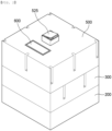
FIG. 2 is a perspective view showing a battery module according to a preferred embodiment of the present invention. -
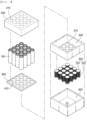
FIG. 3 is an exploded perspective view showing the battery module according to the preferred embodiment of the present invention. -
FIG. 4 is a sectional view showing the battery module according to the preferred embodiment of the present invention. -
FIG. 5 is an exploded perspective view showing a second frame and a heat conduction pad according to a preferred embodiment of the present invention. -
FIG. 6 is a perspective view showing the battery module according to the preferred embodiment of the present invention before a heat conduction unit is attached thereto. -
FIG. 7 is a view showing the operation of an operation unit according to a preferred embodiment of the present invention. - Now, preferred embodiments of the present invention will be described in detail with reference to the accompanying drawings such that the preferred embodiments of the present invention can be easily implemented by a person having ordinary skill in the art to which the present invention pertains. In describing the principle of operation of the preferred embodiments of the present invention in detail, however, a detailed description of known functions and configurations incorporated herein will be omitted when the same may obscure the subject matter of the present invention.
- In addition, the same reference numbers will be used throughout the drawings to refer to parts that perform similar functions or operations. In the case in which one part is said to be connected to another part throughout the specification, not only may the one part be directly connected to the other part, but also, the one part may be indirectly connected to the other part via a further part. In addition, that a certain element is included does not mean that other elements are excluded, but means that such elements may be further included unless mentioned otherwise.
- Hereinafter, a battery module with a heating function according to the present invention will be described with reference to the accompanying drawings.
-
FIG. 2 is a perspective view showing a battery module according to a preferred embodiment of the present invention,FIG. 3 is an exploded perspective view showing the battery module according to the preferred embodiment of the present invention,FIG. 4 is a sectional view showing the battery module according to the preferred embodiment of the present invention,FIG. 5 is an exploded perspective view showing a second frame and a heat conduction pad according to a preferred embodiment of the present invention, andFIG. 6 is a perspective view showing the battery module according to the preferred embodiment of the present invention before a heat conduction unit is attached thereto. - As shown in
FIGs. 2 to 6 , the battery module according to the present invention includes acylindrical battery cell 100, afirst frame 200, asecond frame 300, aheat conduction pad 400, areceiving frame 500, and adisplay unit 600. - First, the
cylindrical battery cell 100 includes an electrode assembly, a cap assembly, and a cylindrical battery case configured to receive the electrode assembly and the cap assembly. - The electrode assembly may be a jelly-roll type electrode assembly, which is configured to have a structure in which a long sheet type negative electrode and a long sheet type positive electrode are wound in the state in which a separator is interposed therebetween.
- The positive electrode includes a positive electrode current collector and a positive electrode active material applied to each of an upper surface and a lower surface of the positive electrode current collector.
- In general, the positive electrode current collector may have a thickness of 3 to 500 µm. The positive electrode current collector is not particularly restricted as long as the positive electrode current collector exhibits high conductivity while the positive electrode current collector does not induce any chemical change in a battery. For example, the positive electrode current collector may be made of stainless steel, aluminum, nickel, titanium, or sintered carbon. Alternatively, the positive electrode current collector may be made of aluminum or stainless steel, the surface of which is treated with carbon, nickel, titanium, or silver. In addition, the positive electrode current collector may have a micro-scale uneven pattern formed on the surface thereof so as to increase adhesion of the positive electrode active material, or may be configured in any of various forms, such as a film, a sheet, a foil, a net, a porous body, a foam body, and a non-woven fabric body.
- A layered compound, such as lithium cobalt oxide (LiCoO2) or lithium nickel oxide (LiNiO2), or a compound substituted with one or more transition metals; a lithium manganese oxide represented by the chemical formula Li1+xMn2-xO4 (where x = 0 to 0.33) or a lithium manganese oxide, such as LiMnO3, LiMn2O3, or LiMnO2; a lithium copper oxide (Li2CuO2) ; a vanadium oxide, such as LiV3O8, V2O5, or Cu2V2O7; a Ni-sited lithium nickel oxide represented by the chemical formula LiNi1-xMxO2 (where M = Co, Mn, Al, Cu, Fe, Mg, B, or Ga, and x = 0.01 to 0.3); a lithium manganese composite oxide represented by the chemical formula LiMn2-xMxO2 (where M = Co, Ni, Fe, Cr, Zn, or Ta, and x = 0.01 to 0.1) or the chemical formula Li2Mn3MO8 (where M = Fe, Co, Ni, Cu, or Zn); LiMn2O4 in which a part of Li in the chemical formula is replaced by alkaline earth metal ions; a disulfide compound; Fe2(MoO4)3, or LiNixMn2-xO4 (0.01 ≤ x ≤ 0.6) may be used as the positive electrode active material.
- Meanwhile, the positive electrode active material may be mixed with a conductive agent and a binder, and a filler may be further added as needed.
- The conductive agent is generally added in an amount of 1 to 50 wt% based on the total weight of the mixture including the positive electrode active material. The conductive agent is not particularly restricted as long as the conductive agent exhibits high conductivity while the conductive agent does not induce any chemical change in a battery. For example, graphite, such as natural graphite or artificial graphite; carbon black, such as carbon black, acetylene black, Ketjen black, channel black, furnace black, lamp black, or thermal black; conductive fiber, such as carbon fiber or metallic fiber; metallic powder, such as carbon fluoride powder, aluminum powder, or nickel powder; conductive whisker, such as zinc oxide or potassium titanate; a conductive metal oxide, such as titanium oxide; or a conductive material, such as a polyphenylene derivative, may be used as the conductive agent.
- The binder is a component assisting in binding between the positive electrode active material and the conductive agent and in binding with the current collector. The binder is generally added in an amount of 1 to 50 wt% based on the total weight of the mixture including the positive electrode active material. As examples of the binder, there may be used polyvinylidene fluoride, polyvinyl alcohol, carboxymethylcellulose (CMC), starch, hydroxypropylcellulose, regenerated cellulose, polyvinyl pyrrolidone, tetrafluoroethylene, polyethylene, polypropylene, ethylene-propylene-diene terpolymer (EPDM), sulfonated EPDM, styrene butadiene rubber, fluoro rubber, and various copolymers.
- The negative electrode includes a negative electrode current collector and a negative electrode active material applied to each of an upper surface and a lower surface of the negative electrode current collector.
- The negative electrode current collector is generally manufactured so as to have a thickness of 3 to 500 µm. The negative electrode current collector is not particularly restricted as long as the negative electrode current collector exhibits high conductivity while the negative electrode current collector does not induce any chemical change in a battery. For example, the negative electrode current collector may be made of copper, stainless steel, aluminum, nickel, titanium, or sintered carbon. Alternatively, the negative electrode current collector may be made of copper or stainless steel, the surface of which is treated with carbon, nickel, titanium, or silver, or an aluminum-cadmium alloy.
- In addition, the negative electrode current collector may have a micro-scale uneven pattern formed on the surface thereof in order to increase adhesion of the negative electrode active material, or may be configured in any of various forms, such as a film, a sheet, a foil, a net, a porous body, a foam body, and a non-woven fabric body.
- As the negative electrode active material, for example, there may be used carbon, such as non-graphitizing carbon or graphite-based carbon; a metal composite oxide, such as LixFe2O3 (0≤x≤1), LixWO2 (0≤x≤1), SnxMe1-xMe'yOz (Me: Mn, Fe, Pb, Ge; Me': Al, B, P, Si, Group 1, 2, and 3 elements of the periodic table, halogen; 0<x≤1; 1≤y≤3; 1≤z≤8); lithium metal; a lithium alloy; a silicon-based alloy; a tin-based alloy; a metal oxide, such as SnO, SnO2, PbO, PbO2, Pb2O3, Pb3O4, Sb2O3, Sb2O4, Sb2O5, GeO, GeO2, Bi2O3, Bi2O4, or Bi2O5; a conductive polymer, such as polyacetylene; a Li-Co-Ni-based material, or a Si-based material, such as Si, SiO, SiO2, or a mixture thereof; however, the present invention is not limited thereto.
- Of course, the negative electrode active material may be further mixed with a conductive agent and a binder, and the negative electrode current collector may be coated with the mixture.
- The conductive agent is a component configured to further improve conductivity of the negative electrode active material, and carbon black, such as acetylene black, Ketjen black, channel black, furnace black, lamp black, or thermal black; conductive fiber, such as carbon fiber or metallic fiber; metallic powder, such as carbon fluoride powder, aluminum powder, or nickel powder; conductive whisker, such as zinc oxide or potassium titanate; a conductive metal oxide, such as titanium oxide; or a conductive material, such as a polyphenylene derivative, may be used in a certain proportion.
- The binder is a component assisting in binding between the negative electrode active material and the conductive agent and in binding with the current collector, and may include at least one selected from the group consisting of styrene butadiene rubber (SBR), acrylonitrile butadiene rubber, acrylic rubber, butyl rubber, fluoro rubber, polyvinyl alcohol, carboxymethyl cellulose (CMC), starch, hydroxypropyl cellulose, regenerated cellulose, polyvinyl alcohol (PVA), polyacrylic acid (PAA), polyethylene glycol (PEG), polyacrylonitrile (PAN), and polyacrylamide (PAM).
- The separator prevents short circuit between the positive electrode and the negative electrode and allows only migration of lithium ions. It is preferable for the separator to be made of any one selected from among polyethylene, polypropylene, a dual layer of polyethylene/polypropylene, a triple layer of polyethylene/polypropylene/polyethylene, a triple layer of polypropylene/polyethylene/polypropylene, and organic fiber filter paper; however, the present invention is not limited thereto.
- The cap assembly is located on the top of the electrode assembly, is electrically connected to a positive electrode tab of the electrode assembly, and is coupled to an upper end of the battery case, which is open, to seal the electrode assembly received in the battery case.
- Specifically, in the cap assembly, a current interrupting member, a current interrupting gasket, a safety vent, a PTC element, and a top cap are sequentially stacked from the bottom, and a crimping gasket is located at outer edges of the current interrupting member and the top cap.
- The current interrupting member, which is also called a current interrupt device (CID), is located on the top of the electrode assembly, and the positive electrode tab is connected to a lower surface of the current interrupting member at a predetermined position.
- The safety vent, which is formed to protrude downward in the center and has one or more first notches, is located on the top of the current interrupting member. The safety vent interrupts current and exhausts the gas in the event of an increase in pressure in the battery case, and is disposed such that one surface of the safety vent is in contact with the PTC element and an edge surface of the safety vent is in contact with the crimping gasket.
- The current interrupting gasket is located such that the current interrupting member and the safety vent remain electrically isolated from each other except for downwardly protruding portions of the current interrupting member and the safety vent.
- The battery case receives the electrode assembly and the cap assembly, and a negative electrode tab extends downward and is connected to the bottom of the battery case such that the bottom of the battery case can act as a negative electrode.
- As described above, the crimping portion, which is configured to seal the cap assembly while wrapping around an outer side surface of the cap assembly, is provided at an upper end of the cylindrical battery case, and an inwardly indented beading portion is provided under the crimping portion to securely fix the electrode assembly and the cap assembly while protecting the electrode assembly and the cap assembly from external impact.
- Next, the
first frame 200 is configured to protect thecylindrical battery cell 100 from external impact or the like, may have a hexahedral shape, and is provided with a receivinghole 210 configured to receive and enclose a part of thecylindrical battery cell 100. - The
first frame 200 may be of a height capable of receiving about half of thecylindrical battery cell 100 when thecylindrical battery cell 100 is received in the receivinghole 210. - The
second frame 300 is configured to protect a part of thecylindrical battery cell 100 not received in thefirst frame 200 from external impact or the like, and may be in the shape of a hexahedron with one side open, and ahole 310 formed through thesecond frame 300 may be provided on the other side surface of the second frame. - Here, the
first frame 100 and thesecond frame 200 may be fastened and fixed to each other using a bolt in a state of being in tight contact with each other, and a fastening method is not particularly restricted as long as thefirst frame 100 and thesecond frame 200 can be fixed to each other in a state of being in tight contact with each other. - The
heat conduction pad 400 may be located inside the surface of thesecond frame 300 where thehole 310 is formed, and may be in the shape of a rectangular sheet. - The
heat conduction pad 400 may have a receivingrecess 410 configured to receive a part of thecylindrical battery cell 100 at the position corresponding to thecylindrical battery cell 100, and the receivingrecess 410 may increase the contact surface area between theheat conduction pad 400 and thecylindrical battery cell 100, thereby improving heat conduction efficiency. - The
heat conduction pad 400 may be made of a material having thermal conductivity and electrical insulation, may include, for example, a silicone-based material, and is not particularly restricted as long as the heat conduction pad is made of a material having excellent thermal conductivity and electrical insulation. - The receiving
frame 500 may be formed in the shape of a hexahedron with one side open, may have a space portion having a predetermined volume, and may include aheating solution 510, anoperation unit 520, and aheat conduction unit 530. - The
heating solution 510 may be received in the space portion formed by the receivingframe 500, and may be a supersaturated solution. - The supersaturated solution may be, for example, an aqueous solution that is supersaturated with sodium acetate, and the supersaturated solution undergoes phase change and dissipates heat when impact is applied thereto.
- In addition, the supersaturated solution has the advantage of being recyclable, as the supersaturated solution can be returned to the supersaturated solution state if heat is applied after the phase change is completed while heat is dissipated.
- The
operation unit 520 is formed on one side of the receivingframe 500, and includes avertical portion 521, aindented portion 522, a pressingmember 523, anoperation control portion 524, and aswitch cap portion 525. - The
vertical portion 521 extends inwardly of the receivingframe 500 and forms the space portion. - The
indented portion 522 may be located at the extended end of thevertical portion 521 and may be formed in a indented shape in the direction toward the space portion formed by thevertical portion 521. - Here, each of the
vertical portion 521 and theindented portion 522 may be made of an elastic material. - The pressing
member 523 may be located in the space portion of thevertical portion 521, and may be configured in a bar shape such that one side of the pressing member is in tight contact with theindented portion 522 and the other side of the pressing member protrudes outwardly of the receivingframe 500. - The
operation control portion 524 may be configured to wrap around a side surface of thepressing member 523 that protrudes outwardly of the receivingframe 500, and may be located such that one side of the operation control portion is in tight contact with the receivingframe 500. - The
operation control portion 524 may fix thepressing member 523 to restrict the movement thereof or release the fixed state thereof to allow thepressing member 523 to move according to a received signal. - In one example, the
operation control portion 524 may be in the shape of a gripper that wraps around the pressingmember 523, and is not particularly restricted as long as the operation control portion has a structure capable of fixing the movement of thepressing member 523 and releasing the fixed state of the pressing member. - The
switch cap portion 525 may be constituted by a side surface part configured to wrap around the pressingmember 523 and theoperation control portion 524 exposed outside the receivingframe 500 and an upper surface part connected to one side of the side surface part by hinge or the like. - The upper surface part of the
switch cap portion 525 is in tight contact with thepressing member 523, whereby pressing force may be transmitted to thepressing member 523 when the upper surface part is pressed. - In this case, a method of connecting the side surface part and the upper surface part of the
switch cap portion 525 to each other is not particularly restricted as long as the pressure is transmitted to thepressing member 523 when pressed in the state of being connected to each other such that thepressing member 523 can be moved. - The
heat conduction unit 530 is configured to transfer heat generated when theheating solution 510 undergoes phase change to thecylindrical battery cell 100, and may include atight contact portion 531 and anextension fin portion 532. - The
tight contact portion 531 is configured to transfer heat generated when the heating solution 51 undergoes phase change to thecylindrical battery cell 100, and may be located so as to be in tight contact with theheat conduction pad 400 exposed through thehole 310 of thesecond frame 300. - The
tight contact portion 531 may be in the form of a thin sheet, and may be formed in a horizontal sectional shape corresponding to thehole 310. Preferably, the area of thetight contact portion 531 is less than or equal to the area of thehole 310. - This is because, if the area of the
tight contact portion 531 is greater than the area of thehole 310, tight contact between thetight contact portion 531 and theheat conduction pad 400 may not be properly achieved. - The
extension fin portion 532 may be formed by extending from one side surface of thetight contact portion 531 in the direction toward the space portion of the receivingframe 500, and may be in the shape of a plurality of thin pins. - As described above, the
extension fin portion 532 has the advantage of being formed in the shape of a plurality of thin pins to form a larger contact area per unit volume with theheating solution 510, thereby improving heat exchange efficiency. - Next, the
display unit 600 is provided on an outer surface of the receivingframe 500, and may be formed in a structure in which a part of the display unit is received in the receivingframe 500 as needed. Thedisplay unit 600 may be provided with a battery management system (BMS). - The
display unit 600 may display whether the battery module needs to be heated and whether theoperation unit 520 needs to be operated, may be, for example, a display capable of displaying text, and may be further provided with aconnection portion 610 and atemperature sensor 620. - The
connection portion 610 connects thedisplay unit 600 and theoperation control portion 524 to each other such that an electrical signal can be transmitted to control the movement of thepressing member 523 through theoperation control portion 524. - The
temperature sensor 620 extends from thedisplay unit 600, measures the temperature of theheating solution 510 received in the receivingframe 500, and provides a measured value that is considered in displaying whether theoperation unit 520 is to be operated on thedisplay unit 600. - In one example, the
display unit 600 may display that theoperation unit 520 does not need to be operated when the temperature of thecylindrical battery cell 100 is equal to or less than a reference value and the temperature of theheating solution 510 measured through thetemperature sensor 620 is high. - In this case, the reference value may be 5 °C, which is the minimum temperature at which charging can be performed, more preferably 15 °C, at which smooth charging can be performed.
- In addition, the
display unit 600 may display that theoperation unit 520 needs to be operated when the temperature of thecylindrical battery cell 100 is equal to or less than the reference value and the temperature of theheating solution 510 measured through thetemperature sensor 620 is low. -
FIG. 7 is a view showing the operation of an operation unit according to a preferred embodiment of the present invention. - When describing the operation of the
operation unit 520 with further reference toFIGs. 2 to 6 , theoperation control portion 524 holds thepressing member 523 in a fixed state when thedisplay unit 600 displays that the operation unit does not need to be operated, as shown inFIG. 7(a) . - When the measured temperature of the
cylindrical battery cell 100 is equal to or less than the reference value and the temperature of theheating solution 510 is low, thedisplay unit 600 displays that that the operation unit needs to be operated. At this time, theoperation control portion 524 releases the fixed state of thepressing member 523 such that thepressing member 523 can move. - Here, pressing the
switch cap portion 525 causes thepressing member 523 to move downward, whereby theindented portion 522 is spread out and impact is generated, which may cause theheating solution 510 to undergo phase change and generate heat. - When the pressure applied to the
switch cap portion 525 is released, as shown inFIG. 7(c) , elastic impact is further applied to theheating solution 510 as the vertical portion and the indented portion return to positions before pressing due to the elastic properties thereof, causing phase change in theheating solution 510. - Those skilled in the art to which the present invention pertains will appreciate that various applications and modifications are possible within the category of the present invention based on the above description.
-
- 100:
- Cylindrical battery cell
- 200:
- First frame
- 210:
- Receiving hole
- 300:
- Second frame
- 310:
- Hole
- 400:
- Heat conduction pad
- 410:
- Recess
- 500:
- Receiving frame
- 510:
- Heating solution
- 520:
- Operation unit
- 521:
- Vertical portion 522: Indented portion
- 523:
- Pressing member 524: Operation control portion
- 525:
- Switch cap portion
- 530:
- Heat conduction unit
- 531:
- Tight contact portion 532: Extension fin portion
- 600:
- Display unit
- 610:
- Connection portion
- 620:
- Temperature sensor
Claims (14)
- A battery module comprising:a plurality of cylindrical battery cells;a first frame having a receiving hole configured to receive the plurality of cylindrical battery cells;a second frame having a plurality of holes incised so as to each have a predetermined area in one side surface thereof, the second frame being coupled to the first frame;a heat conduction pad located inside the second frame, the heat conduction pad being configured to cover the plurality of holes; anda receiving frame having a space portion that is configured to receive a heating solution and an operation unit configured to activate the heating solution, whereina heat conduction unit for heat conduction is provided in the receiving frame.
- The battery module according to claim 1, wherein the heat conduction pad has a recess configured to receive a part of each cylindrical battery cell at a position corresponding to the plurality of cylindrical battery cell.
- The battery module according to claim 2, wherein the plurality of holes is formed at positions corresponding to the recesses.
- The battery module according to claim 1, wherein the operation unit comprises:a vertical portion extending inwardly of the receiving frame, the vertical portion having a predetermined space portion;a indented portion located at an end of the vertical portion, the indented portion being indented in a direction toward the space portion of the vertical portion; anda bar-shaped pressing member configured such that one side of the pressing member is in tight contact with the indented portion and the other side of the pressing member protrudes outside of the receiving frame.
- The battery module according to claim 4, wherein the pressing member is provided at an outwardly protruding part thereof with an operation control portion configured to control movement of the pressing member.
- The battery module according to claim 4, wherein the operation unit further comprises a switch cap portion configured to cover an outwardly protruding part of the pressing member.
- The battery module according to claim 2, wherein the heat conduction unit is located such that one side of the heat conduction unit is in tight contact with the heat conduction pad through the plurality of holes.
- The battery module according to claim 7, wherein the heat conduction unit comprises:a tight contact portion in tight contact with the heat conduction pad; anda plurality of extension fin portions extending from the tight contact portion in a direction toward an inside of the receiving frame.
- The battery module according to claim 8, wherein a thermally conductive adhesive member is applied between the heat conduction pad and the tight contact portion.
- The battery module according to claim 5, wherein the receiving frame is provided on an outer surface having a display unit configured to display when the operation unit needs to be operated.
- The battery module according to claim 10, wherein the display unit is provided with a battery management system (BMS).
- The battery module according to claim 11, wherein the battery management system (BMS) is connected to the operation control portion via a connection portion, and is connected to a temperature sensor mounted in the space portion of the receiving frame.
- The battery module according to claim 1, wherein the heating solution is a supersaturated solution.
- The battery module according to claim 13, wherein the supersaturated solution is a supersaturated aqueous solution of sodium acetate.
Applications Claiming Priority (2)
| Application Number | Priority Date | Filing Date | Title |
|---|---|---|---|
| KR1020230118914A KR20250036990A (en) | 2023-09-07 | 2023-09-07 | Battery Module With Heating Function |
| PCT/KR2024/012463 WO2025053500A1 (en) | 2023-09-07 | 2024-08-21 | Battery module having heating function |
Publications (2)
| Publication Number | Publication Date |
|---|---|
| EP4583252A1 true EP4583252A1 (en) | 2025-07-09 |
| EP4583252A4 EP4583252A4 (en) | 2026-04-08 |
Family
ID=94924332
Family Applications (1)
| Application Number | Title | Priority Date | Filing Date |
|---|---|---|---|
| EP24863081.6A Pending EP4583252A4 (en) | 2023-09-07 | 2024-08-21 | BATTERY MODULE WITH HEATING FUNCTION |
Country Status (6)
| Country | Link |
|---|---|
| EP (1) | EP4583252A4 (en) |
| JP (1) | JP2025535645A (en) |
| KR (1) | KR20250036990A (en) |
| CN (1) | CN119968730A (en) |
| TW (1) | TW202518751A (en) |
| WO (1) | WO2025053500A1 (en) |
Family Cites Families (13)
| Publication number | Priority date | Publication date | Assignee | Title |
|---|---|---|---|---|
| JP4812345B2 (en) * | 2005-06-30 | 2011-11-09 | 三洋電機株式会社 | Power supply |
| CN101242015A (en) * | 2007-02-08 | 2008-08-13 | 佛山市顺德区顺达电脑厂有限公司 | Battery for electronic device |
| KR101219233B1 (en) | 2010-11-19 | 2013-01-09 | 삼성에스디아이 주식회사 | Battery array and battery packs having same |
| JP2014197452A (en) * | 2011-08-03 | 2014-10-16 | パナソニック株式会社 | Battery module |
| KR101526667B1 (en) * | 2013-06-10 | 2015-06-05 | 현대자동차주식회사 | Device for cooling and heating battery module of vehicle |
| JP2015015208A (en) * | 2013-07-08 | 2015-01-22 | 株式会社東芝 | Battery module, power-supply unit including battery module and temperature management method of battery module |
| JP6976762B2 (en) * | 2017-07-21 | 2021-12-08 | 矢崎総業株式会社 | Battery pack |
| KR102353917B1 (en) * | 2018-01-04 | 2022-01-19 | 주식회사 엘지에너지솔루션 | Battery Module Having Heat Conduction Pad |
| KR102498361B1 (en) * | 2019-05-15 | 2023-02-08 | 주식회사 엘지에너지솔루션 | A battery pack having a structure capable of rapid preheating, Battery pack and Vehicle comprising the same |
| CN115552705B (en) * | 2020-09-21 | 2025-12-09 | 株式会社Lg新能源 | Battery module, battery pack, and vehicle including battery module |
| WO2022080686A1 (en) * | 2020-10-12 | 2022-04-21 | 주식회사 엘지에너지솔루션 | Battery module, battery pack, and vehicle |
| CN121775290A (en) | 2020-12-31 | 2026-04-03 | 微创神通医疗科技(上海)有限公司 | A catheter |
| CN114744337A (en) * | 2022-04-27 | 2022-07-12 | 奇瑞汽车股份有限公司 | Battery heating system and new forms of energy electric automobile |
-
2023
- 2023-09-07 KR KR1020230118914A patent/KR20250036990A/en active Pending
-
2024
- 2024-08-21 CN CN202480003940.8A patent/CN119968730A/en active Pending
- 2024-08-21 WO PCT/KR2024/012463 patent/WO2025053500A1/en active Pending
- 2024-08-21 EP EP24863081.6A patent/EP4583252A4/en active Pending
- 2024-08-21 JP JP2025513436A patent/JP2025535645A/en active Pending
- 2024-09-04 TW TW113133361A patent/TW202518751A/en unknown
Also Published As
| Publication number | Publication date |
|---|---|
| WO2025053500A1 (en) | 2025-03-13 |
| CN119968730A (en) | 2025-05-09 |
| JP2025535645A (en) | 2025-10-28 |
| TW202518751A (en) | 2025-05-01 |
| EP4583252A4 (en) | 2026-04-08 |
| KR20250036990A (en) | 2025-03-17 |
Similar Documents
| Publication | Publication Date | Title |
|---|---|---|
| JP3557748B2 (en) | Sealed non-aqueous secondary battery | |
| US20060269831A1 (en) | Pouch type lithium secondary battery | |
| EP1760820A1 (en) | Rectangular lithium secondary battery | |
| EP1998401A2 (en) | Electrode assembley and secondary battery using the same | |
| KR102051926B1 (en) | Battery Pack Comprising Tape Containing Thermochromic Dye | |
| JP2011507208A (en) | Pouch-type secondary battery with improved safety | |
| EP4372882B1 (en) | Battery pack and vehicle including the battery pack | |
| EP3614482B1 (en) | Electrode assembly and method of stabilizing secondary battery | |
| KR102926483B1 (en) | Battery Module, Battery Pack, And Electronic Vehicle Including Same | |
| CA3234390A1 (en) | Lithium secondary battery | |
| KR20100059964A (en) | Sealed battery | |
| KR20180083124A (en) | Pouch forming method of secondary battery | |
| CA3234432A1 (en) | Lithium secondary battery | |
| EP4044331A1 (en) | Pouch-type secondary battery having increased energy density, and method for manufacturing same | |
| CA3233003A1 (en) | Lithium secondary battery | |
| KR20140013177A (en) | Secondary battery and electrochemical cell having the same | |
| KR100875607B1 (en) | Improved safety secondary battery including stacked electrode assembly | |
| JP3627359B2 (en) | Sealed non-aqueous secondary battery | |
| JP4420484B2 (en) | Sealed battery | |
| KR20250036990A (en) | Battery Module With Heating Function | |
| EP4697490A1 (en) | Battery module having improved structure and battery pack including same | |
| KR100614401B1 (en) | Secondary battery | |
| EP4322310A1 (en) | Electrode assembly comprising anode with extension part | |
| EP4297152B1 (en) | Battery case having natural heat dissipation function | |
| JPH07320711A (en) | Sealed nonaqueous secondary battery |
Legal Events
| Date | Code | Title | Description |
|---|---|---|---|
| STAA | Information on the status of an ep patent application or granted ep patent |
Free format text: STATUS: THE INTERNATIONAL PUBLICATION HAS BEEN MADE |
|
| PUAI | Public reference made under article 153(3) epc to a published international application that has entered the european phase |
Free format text: ORIGINAL CODE: 0009012 |
|
| STAA | Information on the status of an ep patent application or granted ep patent |
Free format text: STATUS: REQUEST FOR EXAMINATION WAS MADE |
|
| 17P | Request for examination filed |
Effective date: 20250402 |
|
| AK | Designated contracting states |
Kind code of ref document: A1 Designated state(s): AL AT BE BG CH CY CZ DE DK EE ES FI FR GB GR HR HU IE IS IT LI LT LU LV MC ME MK MT NL NO PL PT RO RS SE SI SK SM TR |
|
| A4 | Supplementary search report drawn up and despatched |
Effective date: 20260305 |
|
| RIC1 | Information provided on ipc code assigned before grant |
Ipc: H01M 10/615 20140101AFI20260227BHEP Ipc: H01M 10/643 20140101ALI20260227BHEP Ipc: H01M 10/653 20140101ALI20260227BHEP Ipc: H01M 10/6551 20140101ALI20260227BHEP Ipc: H01M 10/6554 20140101ALI20260227BHEP Ipc: H01M 10/6567 20140101ALI20260227BHEP Ipc: H01M 10/637 20140101ALI20260227BHEP Ipc: H01M 10/623 20140101ALI20260227BHEP Ipc: H01M 50/213 20210101ALI20260227BHEP Ipc: H01M 50/289 20210101ALI20260227BHEP Ipc: H01M 10/48 20060101ALI20260227BHEP Ipc: H01M 10/625 20140101ALI20260227BHEP Ipc: H01M 10/613 20140101ALI20260227BHEP |