EP4583239A1 - Batteriepack - Google Patents
Batteriepack Download PDFInfo
- Publication number
- EP4583239A1 EP4583239A1 EP24223499.5A EP24223499A EP4583239A1 EP 4583239 A1 EP4583239 A1 EP 4583239A1 EP 24223499 A EP24223499 A EP 24223499A EP 4583239 A1 EP4583239 A1 EP 4583239A1
- Authority
- EP
- European Patent Office
- Prior art keywords
- fuse pattern
- pattern
- battery pack
- fuse
- width
- Prior art date
- Legal status (The legal status is an assumption and is not a legal conclusion. Google has not performed a legal analysis and makes no representation as to the accuracy of the status listed.)
- Pending
Links
Images



Classifications
-
- H—ELECTRICITY
- H01—ELECTRIC ELEMENTS
- H01M—PROCESSES OR MEANS, e.g. BATTERIES, FOR THE DIRECT CONVERSION OF CHEMICAL ENERGY INTO ELECTRICAL ENERGY
- H01M50/00—Constructional details or processes of manufacture of the non-active parts of electrochemical cells other than fuel cells, e.g. hybrid cells
- H01M50/50—Current conducting connections for cells or batteries
- H01M50/502—Interconnectors for connecting terminals of adjacent batteries; Interconnectors for connecting cells outside a battery casing
- H01M50/503—Interconnectors for connecting terminals of adjacent batteries; Interconnectors for connecting cells outside a battery casing characterised by the shape of the interconnectors
-
- H—ELECTRICITY
- H01—ELECTRIC ELEMENTS
- H01M—PROCESSES OR MEANS, e.g. BATTERIES, FOR THE DIRECT CONVERSION OF CHEMICAL ENERGY INTO ELECTRICAL ENERGY
- H01M10/00—Secondary cells; Manufacture thereof
- H01M10/42—Methods or arrangements for servicing or maintenance of secondary cells or secondary half-cells
- H01M10/425—Structural combination with electronic components, e.g. electronic circuits integrated to the outside of the casing
-
- H—ELECTRICITY
- H01—ELECTRIC ELEMENTS
- H01M—PROCESSES OR MEANS, e.g. BATTERIES, FOR THE DIRECT CONVERSION OF CHEMICAL ENERGY INTO ELECTRICAL ENERGY
- H01M10/00—Secondary cells; Manufacture thereof
- H01M10/42—Methods or arrangements for servicing or maintenance of secondary cells or secondary half-cells
- H01M10/48—Accumulators combined with arrangements for measuring, testing or indicating the condition of cells, e.g. the level or density of the electrolyte
- H01M10/482—Accumulators combined with arrangements for measuring, testing or indicating the condition of cells, e.g. the level or density of the electrolyte for several batteries or cells simultaneously or sequentially
-
- H—ELECTRICITY
- H01—ELECTRIC ELEMENTS
- H01M—PROCESSES OR MEANS, e.g. BATTERIES, FOR THE DIRECT CONVERSION OF CHEMICAL ENERGY INTO ELECTRICAL ENERGY
- H01M50/00—Constructional details or processes of manufacture of the non-active parts of electrochemical cells other than fuel cells, e.g. hybrid cells
- H01M50/20—Mountings; Secondary casings or frames; Racks, modules or packs; Suspension devices; Shock absorbers; Transport or carrying devices; Holders
- H01M50/204—Racks, modules or packs for multiple batteries or multiple cells
-
- H—ELECTRICITY
- H01—ELECTRIC ELEMENTS
- H01M—PROCESSES OR MEANS, e.g. BATTERIES, FOR THE DIRECT CONVERSION OF CHEMICAL ENERGY INTO ELECTRICAL ENERGY
- H01M50/00—Constructional details or processes of manufacture of the non-active parts of electrochemical cells other than fuel cells, e.g. hybrid cells
- H01M50/20—Mountings; Secondary casings or frames; Racks, modules or packs; Suspension devices; Shock absorbers; Transport or carrying devices; Holders
- H01M50/258—Modular batteries; Casings provided with means for assembling
-
- H—ELECTRICITY
- H01—ELECTRIC ELEMENTS
- H01M—PROCESSES OR MEANS, e.g. BATTERIES, FOR THE DIRECT CONVERSION OF CHEMICAL ENERGY INTO ELECTRICAL ENERGY
- H01M50/00—Constructional details or processes of manufacture of the non-active parts of electrochemical cells other than fuel cells, e.g. hybrid cells
- H01M50/20—Mountings; Secondary casings or frames; Racks, modules or packs; Suspension devices; Shock absorbers; Transport or carrying devices; Holders
- H01M50/284—Mountings; Secondary casings or frames; Racks, modules or packs; Suspension devices; Shock absorbers; Transport or carrying devices; Holders with incorporated circuit boards, e.g. printed circuit boards [PCB]
-
- H—ELECTRICITY
- H01—ELECTRIC ELEMENTS
- H01M—PROCESSES OR MEANS, e.g. BATTERIES, FOR THE DIRECT CONVERSION OF CHEMICAL ENERGY INTO ELECTRICAL ENERGY
- H01M50/00—Constructional details or processes of manufacture of the non-active parts of electrochemical cells other than fuel cells, e.g. hybrid cells
- H01M50/20—Mountings; Secondary casings or frames; Racks, modules or packs; Suspension devices; Shock absorbers; Transport or carrying devices; Holders
- H01M50/298—Mountings; Secondary casings or frames; Racks, modules or packs; Suspension devices; Shock absorbers; Transport or carrying devices; Holders characterised by the wiring of battery packs
-
- H—ELECTRICITY
- H01—ELECTRIC ELEMENTS
- H01M—PROCESSES OR MEANS, e.g. BATTERIES, FOR THE DIRECT CONVERSION OF CHEMICAL ENERGY INTO ELECTRICAL ENERGY
- H01M50/00—Constructional details or processes of manufacture of the non-active parts of electrochemical cells other than fuel cells, e.g. hybrid cells
- H01M50/30—Arrangements for facilitating escape of gases
- H01M50/383—Flame arresting or ignition-preventing means
-
- H—ELECTRICITY
- H01—ELECTRIC ELEMENTS
- H01M—PROCESSES OR MEANS, e.g. BATTERIES, FOR THE DIRECT CONVERSION OF CHEMICAL ENERGY INTO ELECTRICAL ENERGY
- H01M50/00—Constructional details or processes of manufacture of the non-active parts of electrochemical cells other than fuel cells, e.g. hybrid cells
- H01M50/50—Current conducting connections for cells or batteries
- H01M50/502—Interconnectors for connecting terminals of adjacent batteries; Interconnectors for connecting cells outside a battery casing
- H01M50/507—Interconnectors for connecting terminals of adjacent batteries; Interconnectors for connecting cells outside a battery casing comprising an arrangement of two or more busbars within a container structure, e.g. busbar modules
-
- H—ELECTRICITY
- H01—ELECTRIC ELEMENTS
- H01M—PROCESSES OR MEANS, e.g. BATTERIES, FOR THE DIRECT CONVERSION OF CHEMICAL ENERGY INTO ELECTRICAL ENERGY
- H01M50/00—Constructional details or processes of manufacture of the non-active parts of electrochemical cells other than fuel cells, e.g. hybrid cells
- H01M50/50—Current conducting connections for cells or batteries
- H01M50/502—Interconnectors for connecting terminals of adjacent batteries; Interconnectors for connecting cells outside a battery casing
- H01M50/519—Interconnectors for connecting terminals of adjacent batteries; Interconnectors for connecting cells outside a battery casing comprising printed circuit boards [PCB]
-
- H—ELECTRICITY
- H01—ELECTRIC ELEMENTS
- H01M—PROCESSES OR MEANS, e.g. BATTERIES, FOR THE DIRECT CONVERSION OF CHEMICAL ENERGY INTO ELECTRICAL ENERGY
- H01M50/00—Constructional details or processes of manufacture of the non-active parts of electrochemical cells other than fuel cells, e.g. hybrid cells
- H01M50/50—Current conducting connections for cells or batteries
- H01M50/572—Means for preventing undesired use or discharge
- H01M50/574—Devices or arrangements for the interruption of current
- H01M50/583—Devices or arrangements for the interruption of current in response to current, e.g. fuses
-
- H—ELECTRICITY
- H01—ELECTRIC ELEMENTS
- H01R—ELECTRICALLY-CONDUCTIVE CONNECTIONS; STRUCTURAL ASSOCIATIONS OF A PLURALITY OF MUTUALLY-INSULATED ELECTRICAL CONNECTING ELEMENTS; COUPLING DEVICES; CURRENT COLLECTORS
- H01R25/00—Coupling parts adapted for simultaneous co-operation with two or more identical counterparts, e.g. for distributing energy to two or more circuits
- H01R25/14—Rails or bus-bars constructed so that the counterparts can be connected thereto at any point along their length
-
- H—ELECTRICITY
- H05—ELECTRIC TECHNIQUES NOT OTHERWISE PROVIDED FOR
- H05K—PRINTED CIRCUITS; CASINGS OR CONSTRUCTIONAL DETAILS OF ELECTRIC APPARATUS; MANUFACTURE OF ASSEMBLAGES OF ELECTRICAL COMPONENTS
- H05K1/00—Printed circuits
- H05K1/16—Printed circuits incorporating printed electric components, e.g. printed resistors, capacitors or inductors
-
- H—ELECTRICITY
- H05—ELECTRIC TECHNIQUES NOT OTHERWISE PROVIDED FOR
- H05K—PRINTED CIRCUITS; CASINGS OR CONSTRUCTIONAL DETAILS OF ELECTRIC APPARATUS; MANUFACTURE OF ASSEMBLAGES OF ELECTRICAL COMPONENTS
- H05K2201/00—Indexing scheme relating to printed circuits covered by H05K1/00
- H05K2201/10—Details of components or other objects attached to or integrated in a printed circuit board
- H05K2201/10007—Types of components
- H05K2201/10181—Fuse
-
- Y—GENERAL TAGGING OF NEW TECHNOLOGICAL DEVELOPMENTS; GENERAL TAGGING OF CROSS-SECTIONAL TECHNOLOGIES SPANNING OVER SEVERAL SECTIONS OF THE IPC; TECHNICAL SUBJECTS COVERED BY FORMER USPC CROSS-REFERENCE ART COLLECTIONS [XRACs] AND DIGESTS
- Y02—TECHNOLOGIES OR APPLICATIONS FOR MITIGATION OR ADAPTATION AGAINST CLIMATE CHANGE
- Y02E—REDUCTION OF GREENHOUSE GAS [GHG] EMISSIONS, RELATED TO ENERGY GENERATION, TRANSMISSION OR DISTRIBUTION
- Y02E60/00—Enabling technologies; Technologies with a potential or indirect contribution to GHG emissions mitigation
- Y02E60/10—Energy storage using batteries
Definitions
- the present disclosure relates to a battery pack.
- Secondary batteries are designed to be rechargeable, and may be used as energy sources of devices, such as mobile devices, electric vehicles, hybrid electric vehicles, electric bicycles, or uninterruptible power supplies.
- the secondary battery may be used as a single battery cell, or as a module or pack in which a plurality of battery cells are connected into a unit.
- a battery pack according to embodiments may enable reuse of a circuit board without replacing all or part of the circuit board, even if a short circuit or an electrostatic discharge (ESD) occurs.
- ESD electrostatic discharge
- a battery pack includes a battery module including battery cells, and busbars electrically connecting respective ones of the battery cells, and a circuit board connected to the battery module, and including a first part including wires, and extending in a length direction of the battery module, second parts extending from the first part in a direction crossing the first part, and including a circuit pattern including a fuse pattern configured to be opened (e.g. melted, disrupted) based on an abnormal current, and a non-fuse pattern configured to maintain electrical connection with one or more of the busbars, and third parts respectively extending from the second parts, and connected to the busbars.
- a battery module including battery cells, and busbars electrically connecting respective ones of the battery cells, and a circuit board connected to the battery module, and including a first part including wires, and extending in a length direction of the battery module, second parts extending from the first part in a direction crossing the first part, and including a circuit pattern including a fuse pattern configured to be opened (e.g. melted, disrupte
- a width of the fuse pattern may be less than a width of the non-fuse pattern.
- the width of the fuse pattern may be 20% to 60% of the width of the non-fuse pattern.
- An open time of the fuse pattern during which the fuse pattern ruptures based on the abnormal current through the circuit pattern may be less (shorter) than or equal to half of an open time of the non-fuse pattern.
- the fuse pattern and the non-fuse pattern may be spaced apart from a central portion of the second part in a width direction of the second part.
- One of the second parts may further include a connection area at an end thereof that is connected to the fuse pattern, to the non-fuse pattern, and to the third part.
- the circuit pattern may further include a block pattern between the fuse pattern and the non-fuse pattern that is configured to block an arc generated due to the fuse pattern being opened.
- the block pattern may be spaced apart from the fuse pattern, from the non-fuse pattern, and from the connection area, and may be electrically separated from the wires.
- the first part may further include first guides respectively on both sides thereof in a width direction of the first part, wherein the second part further includes two second guides respectively on both sides thereof in a width direction of the second part, and extending from or spaced apart from the first guides with the circuit pattern between the two second guides.
- An empty safety area may be defined between the second guides and the fuse pattern, and between the fuse pattern and the block pattern.
- a width of the safety area may be 30% to 40% of a width between the two second guides.
- the second guides may extend further toward the third part than the fuse pattern and the non-fuse pattern, and may overlap the connection area in the width direction of the second part.
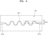
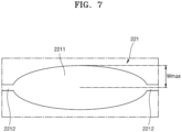
- the fuse pattern may include a bent portion having a wavy shape, and extending portions respectively connected to both ends of the bent portion in a length direction, and connecting the bent portion to the first part and the third part, respectively.
- the bent portion may have a shape in which convex portions and concave portions are continuous at equal intervals, and a distance between adjecent ridges is 1.5 times to 3 times a total width of the bent portion.
- the bent portion of the fuse pattern may comprise or consists of a swellable material.
- spatially relative terms such as “below,” “on,” “lower,” “upper,” and the like, may be used herein for ease of explanation to describe one element or feature's relationship to another element or feature as illustrated in the drawings.
- the spatially relative terms are intended to encompass different orientations of the device in use or in operation, in addition to the orientation depicted in the drawings. For example, if the device in the drawings is turned over, elements described as being “below” or “lower” is oriented “on” another element or feature. Thus, the example terms “below” and “lower” may encompass both orientations of "above” and “lower”.
- the device may be otherwise oriented (e.g., rotated 90 degrees or at other orientations) and the spatially relative descriptors used herein should be interpreted accordingly. Similarly, if a first part is described as being arranged "on" a second part, this indicates that the first part is arranged at an upper side or a lower side of the second part.
- the expression “viewed from a plane” refers to a view of an object part from above
- the expression “in a schematic cross-sectional view” refers to a schematic cross-section taken along a vertical line passing through the object part.
- the expression “viewed from a side” means that a first object may be above, below, or to the side of a second object and vice versa.
- the term “overlapping” may refer to layers, a stack, surfaces, extension, covering, partially covering, or any other suitable terms that would be understood by those of skill in the art.
- the expression “does not overlap” may include meanings, such as “apart from,” “separated from,” or any other suitable equivalents recognized and understood by those of skill in the art.
- face and surface may mean that a first object may directly or indirectly face a second object. If a third object is between a first object and a second object, it may be understood that the first object and the second object face each other but indirectly oppose each other.
- an element, layer, region, or component is referred to as being “formed on,” “connected to,” or “coupled to” another device, it may be directly formed on, a layer, region, or component, formed on another component, layer, region, or component, or indirectly formed on, connected to, or coupled to another component. In addition, this may collectively mean direct or indirect coupling or connection and integral or non-integral coupling or connection of one or more elements, layers, regions, or components to enable the presence of the elements, layers, regions, or components.
- an element, layer, region, or component may be directly electrically connected or coupled to each other, or other elements, layers, regions, or components may be present.
- directly connected or “directly coupled” refers to one component being directly connected or coupled to another component without an intermediate component, or being on the other component.
- the formation direction is not limited to the upward direction, and encompasses that the part is formed on a side surface or a lower portion of the other part. On the contrary, if part of a layer, film, region, plate, etc.
- an element or layer is referred to as being “between” two elements or layers, it may be the only element or layer between the two elements or layers, or one or more intervening elements or layers may be present between the two elements or layers.
- expressions such as “at least one of,” “any one” do not limit the order of individual elements.
- “at least one of X, Y, and Z,” “at least one of X, Y, or Z,” and “at least one selected from the group consisting of X, Y, and Z” may be construed as X only, Y only, Z only, any combination of two or more of X, Y, and Z.
- an expression, such as “at least one of A and B” or “at least one of A or B” may include A, B, or A and B.
- the term “and/or” includes any and all combinations of one or more of the associated listed items.
- an expression, such as “A and/or B” may include A, B, or A and B.
- first,” “second,” or “third,” etc. may be used herein to describe various elements, components, regions, layers, and/or cross sections, these elements, components, regions, layers and/or sections are not limited by these terms. These terms are used to distinguish one element, component, region, layer, or cross section from another element, component, region, layer, or cross section. Thus, a first element, component, region, layer, or cross section described below may be referred to as a second element, component, region, layer, or cross section, without departing from the scope of the present disclosure. The description of an element as a "first” element may not require or imply the presence of a second element or other elements.
- the terms “first,” “second,” etc. may also be used herein to differentiate different categories or sets of elements. For clarity, the terms “first,” “second,” etc. may refer to a "first category (or first set),” a “second category (or second set),” etc., respectively.
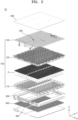
- the battery pack 10 includes one or more battery modules 100 and may be applied to various applications.
- the battery pack 10 may be applied to large-sized applications, such as an energy storage system (ESS), or small-sized and medium-sized applications, such as various electronic devices including power tools.
- the battery pack 10 may be included in the vehicle 1, referring to FIG. 1 .
- the vehicle 1 may be an electric vehicle, a hybrid vehicle, or a plug-in hybrid vehicle.
- the vehicle 1 may be a four-wheeled vehicle or a two-wheeled vehicle.
- the battery pack 10 may be arranged inside a frame 2 of the vehicle 1.
- the battery pack 10 may be between a front part 4 and a rear part 5 of the vehicle 1 and between two wheels 3, and may be below an internal space 6 in which a user sits.
- the busbars 130 may be connected to the plurality of battery cells C.
- the busbars 130 may be on the upper holder 120, and may be electrically connected to the plurality of battery cells C and to the tabs 140.
- the busbars 130 may extend between the plurality of battery cells C (e.g., in plan view), such that upper portions of the plurality of battery cells C are exposed through the openings of the upper holder 120.
- the busbar 130 may include a conductive material, such as metal.
- One busbar 130 may be included in one battery module 100.
- the tabs 140 may electrically connect the battery cells C to the busbars 130.
- one end of the tab 140 may be connected to the busbar 130, and the other end may be connected to the battery cell C.
- the tab 140 may include a conductive material, such as metal, and may have the shape of a wire of which one or more sections are bent.
- a plurality of tabs 140 may be provided.
- One battery cell C may be connected to one or more tabs 140.
- two tabs 140 may be connected to one battery cell C.
- One end of a tab 140 may be connected to the upper surface of a corresponding battery cell C, and the other end of the tab 140 may be connected to the upper surface of the busbar 130.
- One end of another tab 140 may be connected to an upper edge of the corresponding battery cell C, and the other end may be connected to the upper surface of the busbar 130.
- the circuit board 200 may be connected to the busbar 130 to detect the state of each battery module 100, and to control the battery module 100.
- the circuit board 200 may be connected to a controller or a battery management system (BMS), and may measure the voltage, temperature, and/or the like of each battery cell C included in the battery module 100, and may deliver a result of the measuring to the BMS.
- the BMS may control the battery module 100 through the circuit board 200.
- the circuit board 200 may be a flexible printed circuit assembly (FPCA), and may include a flexible printed circuit board (FPCB) and components mounted on the FPCA.
- FPCA flexible printed circuit assembly
- FPCB flexible printed circuit board
- the circuit board 200 may be between the battery module 100 and the upper plate 400.
- the circuit board 200 may be on the battery module 100.
- a portion of the circuit board 200 e.g., the first part 210 of the circuit board 200
- another portion of the circuit board 200 e.g., the second parts 220 and the third parts 230 of the circuit board 200
- One or more circuit boards 200 may be included in the battery pack 10.
- the first part 210 may include the wires 211.
- the first part 210 may include a plurality of wires 211 on the upper surface thereof.
- the wires 211 may be connected to the fuse patterns 221 and to the non-fuse patterns 223 included in the second parts 220, respectively.
- the wires 211 may include a first part 2111 and a second part 2112.
- the first part 2111 may be connected to the fuse pattern 221, and the second part 2112 may be connected to the non-fuse pattern 223.
- the plurality of wires 211 may extend in the length direction of the first part 210, and may include metal, such as copper, silver, or aluminum.
- the first part 2111 and the second part 2112 may extend around a block pattern 222 (e.g., an island portion 2222 of the block pattern 222), and may be spaced apart from the island portion 2222 (e.g., in plan view).
- One or more second parts 220 may extend from the first part 210.
- a plurality of second parts 220 may extend toward the busbars 130 in a direction crossing the direction in which the first part 210 extends.
- the third part 230 may be connected to an end of the second part 220, and may be connected to the busbar 130 such that the busbar 130 and the circuit board 200 may be connected to each other.
- the circuit pattern P may include the fuse pattern 221, the block pattern 222, and the non-fuse pattern 223.
- the fuse pattern 221 may be connected to any one of the plurality of wires 211, and may be connected to a connection area 224. If an abnormal operation, such as a short circuit or an electrostatic discharge (ESD) occurs in the battery pack 10, the fuse pattern 221 may blow (melt and disconnect) to protect the connected busbar 130 and the BMS, and may open the circuit.
- the fuse pattern 221 may be between the second guide 225 and the block pattern 222.
- the fuse pattern 221 may be opened (melted) earlier than the non-fuse pattern 223.
- the fuse pattern 221 may have a width that is less than a width of the non-fuse pattern 223.
- the width of the fuse pattern 221 may refer to the width (thickness) of the wire forming a bent portion 2211 of the fuse pattern 221.
- an abnormal current such as a short circuit or electrical noise
- an open time of the fuse pattern 221 may be shorter than an open time of the non-fuse pattern 223.
- the fuse pattern 221 may melt and disrupt faster than the non-fuse pattern 223.
- the width of the fuse pattern 221 may be (about) 20% to (about) 60% of the width of the non-fuse pattern 223. If the width of the fuse pattern 221 is less than (about) 20% of the width of the non-fuse pattern 223, the fuse pattern 221 may rupture too easily/quickly. If the width of the fuse pattern 221 is greater than (about) 60% of the width of the non-fuse pattern 223, the fuse pattern 221 may rupture too late, and may affect the non-fuse pattern 223.
- the open time of the fuse pattern 221 i.e., the time suitable for the fuse pattern 221 to melt, rupture, break, or burst to result in any form of breakage of the fuse pattern 221 may be shorter than or equal to (about) half of the open time of the non-fuse pattern 223.
- the fuse pattern 221 may include the bent portion 2211 and an extending portion 2212.
- the bent portion 2211 may be between two extending portions 2212, and may be a portion that breaks if an abnormal current occurs, such as an external short circuit, electrical noise, or an ESD.
- the bent portion 2211 may have a wavy shape.
- the bent portion 2211 may then include one or more convex portions and one or more concave portions.
- the bent portion 2211 may have a wavy shape, such as a sine wave shape.
- the bent portion 2211 may have a shape in which convex portions and concave portions of corresponding sizes are continuous at equal or different intervals.
- the distance between adjacent valleys or between adjacent ridges of the bent portion 2211 may be L1.
- the distance L1 may be greater than an initial width W1 of the bent portion 2211 before expansion.
- L1 may be between (about) 1.5 times and (about) 3 times the initial width W1. If the distance L1 is less than (about) 1.5 times the initial width W1, the interval between the valleys or ridges of the bent portion 2211 may be significantly low, and the bent portion 2211 may be opened due to interference even if only a slightly abnormal current flows. If L1 is greater than (about) 3 times the initial width W1, the interval between the valleys or ridges of the bent portion 2211 may be significantly high, and the bent portion 2211 may not be opened in an appropriate amount of time.
- the extending portions 2212 may be connected to both ends of the bent portion 2211 in the length direction, respectively. Any one extending portion 2212 may be connected to the wires 211, and the other extending portion 2212 may be connected to the connection area 224.
- the width (thickness) of the extending portion 2212 may be greater than the width (thickness) of the bent portion 2211.
- the extending portion 2212 may connect the bent portion 2211 to the first part 210 and the third part 230.
- the block pattern 222 may be between the fuse pattern 221 and the non-fuse pattern 223.
- the block pattern 222 may be spaced apart from the fuse pattern 221 and from the non-fuse pattern 223.
- the block pattern 222 may block an arc that occurs if the fuse pattern 221 is opened, and may reduce or prevent the likelihood of the arc affecting the non-fuse pattern 223.
- the block pattern 222 may be spaced apart from the connection area 224, and an end of the block pattern 222 may be spaced apart from the connection area 224 by a distance L2.
- the block pattern 222 may be spaced apart from the wires 211 and other circuit patterns P.
- the block pattern 222 may be separated from the wires 211, the fuse pattern 221, and the non-fuse pattern 223.
- the block pattern 222 may include a block portion 2221 and the island portion 2222.
- the safety area may be a spacing area between the block portion 2221 and the fuse pattern 221, and between the block portion 2221 and the non-fuse pattern 223, to reduce or prevent the likelihood of an arc, which may be generated as the fuse pattern 221 is opened, affecting the non-fuse pattern 223.
- One end of the block portion 2221 may be connected to the island portion 2222, and the other end may be spaced apart from the connection area 224 by the distance L2.
- the width W2 of the block portion 2221 may be greater than the thickness of the bent portion 2211 of the fuse pattern 221, and may be greater than or equal to the width (thickness) W3 of the non-fuse pattern 223.
- the fuse pattern 221 and the non-fuse pattern 223 may be spaced apart from a central portion in the width direction of the second part 220, and in different respective directions (e.g., in opposite directions).
- the fuse pattern 221 and the non-fuse pattern 223 may not overlap a central portion of the second part 220 in the width direction.
- the fuse pattern 221 may be adjacent to one side of the second part 220 in the width direction
- the non-fuse pattern 223 may be adjacent to the other side of the second part 220 in the width direction.
- the second part 220 may further include a safety area 226.
- a safety area 226 For example, referring to FIG. 5 , areas between the second guide 225 and the fuse pattern 221, and between the fuse pattern 221 and the block pattern 222, may be empty. The areas may form the safety area 226 that allows an arc, which may be generated if the fuse pattern 221 breaks, to be discharged to the surrounding area to avoid affecting the non-fuse pattern 223.
- the width of the safety area 226 may be (about) 30% to (about) 40% of a width Wt between the two second guides 225.
- the width of the safety area 226 may be the sum of the widths between the second guide 225 and the fuse pattern 221 and between the fuse pattern 221 and the block pattern 222.
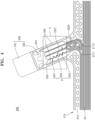
- the third part 230 may include a cell contact portion 231 and a substrate contact portion 232.
- a portion of the cell contact portion 231 may contact the upper surface of the busbar 130, and the other portion of the cell contact portion 231 may be on the second part 220.
- One or more substrate contact portions 232 may protrude on the side of the cell contact portion 231 facing the circuit pattern P.
- two substrate contact portions 232 may be connected to the connection area 224.
- the battery pack 10 may further include the lower plate 300, the upper plate 400, the frame 500, and the heat dissipation member 600.
- the lower plate 300 may be at a lower portion of the battery pack 10, and may be supported by the frame 500.
- the lower plate 300 may have a size corresponding to one or more battery modules 100, and may have a flat shape.
- the lower plate 300 may be below the battery module 100, and an edge thereof may be connected to the frame 500.
- the lower plate 300 may be a cooling plate for cooling the battery pack 10.
- the lower plate 300 may include a material with high thermal conductivity (e.g., aluminum or copper), and may discharge heat generated in the battery module 100 to the outside.
- the lower plate 300 may include a flow path through which a cooling fluid (e.g., a coolant or air) flows.
- the heat dissipation member 600 may be coated on the lower plate 300.
- the upper plate 400 may be at an upper portion of the battery pack 10, and may be supported by the frame 500.
- the upper plate 400 may have a size corresponding to one or more battery modules 100, and may have a flat shape.
- the upper plate 400 may be on the battery module 100, and an edge thereof may be connected to the frame 500.
- the upper plate 400 may be on the busbars 130 and the circuit board 200 of the battery module 100.
- the upper plate 400 may be a fire reduction/prevention plate to reduce or prevent flame propagation in the battery pack 10.
- the upper plate 400 may include mica.
- the upper plate 400 may allow a flame generated from one battery cell C to remain inside the lower holder 110 and the upper holder 120 without propagating to the outside of the battery module 100.
- a non-fuse pattern may maintain electrical connection between a battery module and a circuit board, even if electrical noise or an external short circuit occurs in the circuit board, or if an abnormal current flows to cause a short circuit in a fuse pattern.
- the circuit board may operate through the non-fuse pattern without the need to replace the circuit board.
Landscapes
- Chemical & Material Sciences (AREA)
- Chemical Kinetics & Catalysis (AREA)
- Electrochemistry (AREA)
- General Chemical & Material Sciences (AREA)
- Engineering & Computer Science (AREA)
- Microelectronics & Electronic Packaging (AREA)
- Manufacturing & Machinery (AREA)
- Battery Mounting, Suspending (AREA)
- Connection Of Batteries Or Terminals (AREA)
Applications Claiming Priority (1)
| Application Number | Priority Date | Filing Date | Title |
|---|---|---|---|
| KR1020240001519A KR20250106918A (ko) | 2024-01-04 | 2024-01-04 | 배터리 팩 |
Publications (1)
| Publication Number | Publication Date |
|---|---|
| EP4583239A1 true EP4583239A1 (de) | 2025-07-09 |
Family
ID=94128666
Family Applications (1)
| Application Number | Title | Priority Date | Filing Date |
|---|---|---|---|
| EP24223499.5A Pending EP4583239A1 (de) | 2024-01-04 | 2024-12-27 | Batteriepack |
Country Status (4)
| Country | Link |
|---|---|
| US (1) | US20250226556A1 (de) |
| EP (1) | EP4583239A1 (de) |
| KR (1) | KR20250106918A (de) |
| CN (1) | CN120261921A (de) |
Cited By (1)
| Publication number | Priority date | Publication date | Assignee | Title |
|---|---|---|---|---|
| EP4621925A1 (de) * | 2024-03-22 | 2025-09-24 | Samsung Sdi Co., Ltd. | Batteriepack |
Citations (2)
| Publication number | Priority date | Publication date | Assignee | Title |
|---|---|---|---|---|
| US20180198110A1 (en) * | 2017-01-09 | 2018-07-12 | Molex, Llc | Circuit board and battery connection module |
| CN218939964U (zh) * | 2022-11-30 | 2023-04-28 | 天津市捷威动力工业有限公司 | 保险结构、fpc结构及电子设备 |
-
2024
- 2024-01-04 KR KR1020240001519A patent/KR20250106918A/ko active Pending
- 2024-12-13 US US18/981,125 patent/US20250226556A1/en active Pending
- 2024-12-25 CN CN202411921482.4A patent/CN120261921A/zh active Pending
- 2024-12-27 EP EP24223499.5A patent/EP4583239A1/de active Pending
Patent Citations (2)
| Publication number | Priority date | Publication date | Assignee | Title |
|---|---|---|---|---|
| US20180198110A1 (en) * | 2017-01-09 | 2018-07-12 | Molex, Llc | Circuit board and battery connection module |
| CN218939964U (zh) * | 2022-11-30 | 2023-04-28 | 天津市捷威动力工业有限公司 | 保险结构、fpc结构及电子设备 |
Cited By (1)
| Publication number | Priority date | Publication date | Assignee | Title |
|---|---|---|---|---|
| EP4621925A1 (de) * | 2024-03-22 | 2025-09-24 | Samsung Sdi Co., Ltd. | Batteriepack |
Also Published As
| Publication number | Publication date |
|---|---|
| CN120261921A (zh) | 2025-07-04 |
| KR20250106918A (ko) | 2025-07-11 |
| US20250226556A1 (en) | 2025-07-10 |
Similar Documents
| Publication | Publication Date | Title |
|---|---|---|
| US12355090B2 (en) | Battery module including base plate having gas discharge passage, and battery pack and energy storage system including the same | |
| US20230231290A1 (en) | Battery pack | |
| EP4191780B1 (de) | Batteriemodul mit mehreren parallelen batteriezellen | |
| US10796873B2 (en) | Fusible link in battery module voltage sensing circuit | |
| JP7378593B2 (ja) | 電池モジュールおよびこれを含む電池パック | |
| KR102860577B1 (ko) | 전지 모듈 및 이를 포함하는 전지팩 | |
| EP4583239A1 (de) | Batteriepack | |
| CN220368089U (zh) | 具有提高的安全性的电池组以及包括该电池组的能量存储系统和车辆 | |
| JP7704460B2 (ja) | 開口部を含むパターンヒューズ及びこれを含む電池モジュール | |
| WO2025092199A1 (zh) | 电池包及用电设备 | |
| JP7729689B2 (ja) | パターンヒューズ及びその製造方法 | |
| KR20220000638A (ko) | 전지 모듈 및 이를 포함하는 전지 팩 | |
| KR102798547B1 (ko) | 전지 모듈 및 이를 포함하는 전지 팩 | |
| CN119585941A (zh) | 汇流条组件及包括该汇流条组件的电池组 | |
| CN119487694A (zh) | 汇流条组件及包括该汇流条组件的电池组 | |
| EP4102634A1 (de) | Batteriemodul und batteriepack damit | |
| US20250300303A1 (en) | Battery pack | |
| CN117438632B (zh) | 安全型锂电池模组的生产方法 | |
| EP4645532A1 (de) | Batteriemodul und batteriepack sowie fahrzeug damit | |
| WO2025185108A1 (zh) | 一种电池、电池包、用电装置和电池模组 | |
| JP2025133055A (ja) | バッテリパック | |
| KR20250110492A (ko) | 연성회로기판, 이를 포함하는 배터리 모듈 및 배터리 팩 | |
| KR20250015921A (ko) | 배터리 팩 | |
| KR20250015793A (ko) | 배터리 팩 | |
| KR20080048851A (ko) | 배터리 팩 |
Legal Events
| Date | Code | Title | Description |
|---|---|---|---|
| PUAI | Public reference made under article 153(3) epc to a published international application that has entered the european phase |
Free format text: ORIGINAL CODE: 0009012 |
|
| STAA | Information on the status of an ep patent application or granted ep patent |
Free format text: STATUS: REQUEST FOR EXAMINATION WAS MADE |
|
| 17P | Request for examination filed |
Effective date: 20241227 |
|
| AK | Designated contracting states |
Kind code of ref document: A1 Designated state(s): AL AT BE BG CH CY CZ DE DK EE ES FI FR GB GR HR HU IE IS IT LI LT LU LV MC ME MK MT NL NO PL PT RO RS SE SI SK SM TR |