EP4583084A2 - Système de détection d'anomalie d'écran d'affichage - Google Patents
Système de détection d'anomalie d'écran d'affichage Download PDFInfo
- Publication number
- EP4583084A2 EP4583084A2 EP25150114.4A EP25150114A EP4583084A2 EP 4583084 A2 EP4583084 A2 EP 4583084A2 EP 25150114 A EP25150114 A EP 25150114A EP 4583084 A2 EP4583084 A2 EP 4583084A2
- Authority
- EP
- European Patent Office
- Prior art keywords
- luminosity
- signature
- display
- frames
- measurements
- Prior art date
- Legal status (The legal status is an assumption and is not a legal conclusion. Google has not performed a legal analysis and makes no representation as to the accuracy of the status listed.)
- Pending
Links
Images


Classifications
-
- G—PHYSICS
- G09—EDUCATION; CRYPTOGRAPHY; DISPLAY; ADVERTISING; SEALS
- G09G—ARRANGEMENTS OR CIRCUITS FOR CONTROL OF INDICATING DEVICES USING STATIC MEANS TO PRESENT VARIABLE INFORMATION
- G09G3/00—Control arrangements or circuits, of interest only in connection with visual indicators other than cathode-ray tubes
- G09G3/006—Electronic inspection or testing of displays and display drivers, e.g. of LED or LCD displays
-
- G—PHYSICS
- G09—EDUCATION; CRYPTOGRAPHY; DISPLAY; ADVERTISING; SEALS
- G09G—ARRANGEMENTS OR CIRCUITS FOR CONTROL OF INDICATING DEVICES USING STATIC MEANS TO PRESENT VARIABLE INFORMATION
- G09G5/00—Control arrangements or circuits for visual indicators common to cathode-ray tube indicators and other visual indicators
- G09G5/10—Intensity circuits
-
- G—PHYSICS
- G09—EDUCATION; CRYPTOGRAPHY; DISPLAY; ADVERTISING; SEALS
- G09G—ARRANGEMENTS OR CIRCUITS FOR CONTROL OF INDICATING DEVICES USING STATIC MEANS TO PRESENT VARIABLE INFORMATION
- G09G2320/00—Control of display operating conditions
- G09G2320/02—Improving the quality of display appearance
- G09G2320/0247—Flicker reduction other than flicker reduction circuits used for single beam cathode-ray tubes
-
- G—PHYSICS
- G09—EDUCATION; CRYPTOGRAPHY; DISPLAY; ADVERTISING; SEALS
- G09G—ARRANGEMENTS OR CIRCUITS FOR CONTROL OF INDICATING DEVICES USING STATIC MEANS TO PRESENT VARIABLE INFORMATION
- G09G2320/00—Control of display operating conditions
- G09G2320/06—Adjustment of display parameters
- G09G2320/0626—Adjustment of display parameters for control of overall brightness
-
- G—PHYSICS
- G09—EDUCATION; CRYPTOGRAPHY; DISPLAY; ADVERTISING; SEALS
- G09G—ARRANGEMENTS OR CIRCUITS FOR CONTROL OF INDICATING DEVICES USING STATIC MEANS TO PRESENT VARIABLE INFORMATION
- G09G2340/00—Aspects of display data processing
- G09G2340/04—Changes in size, position or resolution of an image
- G09G2340/0407—Resolution change, inclusive of the use of different resolutions for different screen areas
- G09G2340/0435—Change or adaptation of the frame rate of the video stream
-
- G—PHYSICS
- G09—EDUCATION; CRYPTOGRAPHY; DISPLAY; ADVERTISING; SEALS
- G09G—ARRANGEMENTS OR CIRCUITS FOR CONTROL OF INDICATING DEVICES USING STATIC MEANS TO PRESENT VARIABLE INFORMATION
- G09G2360/00—Aspects of the architecture of display systems
- G09G2360/14—Detecting light within display terminals, e.g. using a single or a plurality of photosensors
- G09G2360/145—Detecting light within display terminals, e.g. using a single or a plurality of photosensors the light originating from the display screen
-
- H—ELECTRICITY
- H04—ELECTRIC COMMUNICATION TECHNIQUE
- H04N—PICTORIAL COMMUNICATION, e.g. TELEVISION
- H04N17/00—Diagnosis, testing or measuring for television systems or their details
- H04N17/04—Diagnosis, testing or measuring for television systems or their details for receivers
Definitions
- Display screens are employed in many computing systems for providing visual user interfaces to operators as well as for display of various media or content.
- the display screens contain various hardware elements, such as display panels, backlights, panel driver circuitry, and display communication links which couple to a computing system having software elements providing graphics that are displayed.
- various updates or changes to software or hardware elements of a computing system having a display can produce unwanted behavior in the display of graphics due to bugs, interoperability issues, unforeseen impacts, and other problems.
- fault detection testing or other verification/validation testing is often performed for various components of a computing system.
- issues exhibited by display of graphics or media content over time can be difficult or cumbersome to detect. This can be especially difficult during playback monitoring of large media files comprising very dense data sets as displays comprise ever-increasing screen resolutions and pixel densities.
- Transient events can include flicker events, which are visual anomalies that produce rapid unwanted visual changes to a display, such as screen blanking events or screen color saturation events.
- Fault or anomaly detection during testing of computing systems can be employed to verify operation of display screens and the various elements forming a computing device coupled to the display screen, which include software elements that generate the graphics, user interface elements, or other visual data ultimately displayed on the display screen.
- One of the challenges in developing and testing software for computing devices is to detect and report any visual or audible problems introduced from software (or changes thereto) which may affect the customer experience.
- individual devices might exhibit failures from unwanted transient behavior exhibited by a display screen during fault detection, manufacturing testing, or other processes.
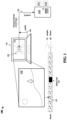
- Test graphics 130 can comprise playback of media content, sequences of user interface graphics, or other sequences of changing displayed graphics. While a static image might be displayed on display screen 111, multi-point luminosity measurements can be obtained by test fixture 120 typically are made over time using changing graphics or images, such as encountered during movie playback, on-screen animations, user interface interactions, computer startup/boot processes, automated scripting of dynamic user interface activities, and the like. Display of graphics or other images on display screen 111 has a granularity of individual frames which are refreshed periodically according to a display refresh rate, which can be separate from any media frame rate.
- the present luminosity signature might be shifted in time as compared to the reference luminosity processor.
- a time shift process can be performed to align the present luminosity signature to the reference luminosity signature, which might be keyed off of various trigger events, such as a start time of sequence of frames or a comparison over a segment of the frames to align various events among the luminosity signatures.
- Luminosity processor 142 can process the present luminosity signature against the reference luminosity signature to align the luminosity signature with respect to the reference luminosity signature in time according to luminosity events correlated among the luminosity signature and the reference luminosity signature.
- a low frequency cut off frequency can be approximately 1 Hz
- a high frequency cut off frequency can be approximately 4 Hz.
- signals which have amplitudes above a threshold amplitude after application of the filter can indicate transient anomalies, such as screen flicker.
- Frequency domain processing provides several technical effects and technical benefits, among which include increased processing efficiency and/or accuracy of identifying relevant flickering or other anomalies within luminosity signatures.
- Luminosity processor 142 can then correlate any discovered transient anomalies to operating system log events for test device 110 generating the series of frames and comprising the measured display screen 111. Luminosity processor 142 can correlate or align in time the transient anomalies to the operating system log events based at least on a trigger event in the operating system log events indicating a graphics rendering start time for the series of frames. This graphics rendering start time might correspond to a graphics video decode engine ramping activity up from an idle or steady-state level of activity to a higher level of activity, such as a quick ramp or step-change in activity levels.
- the activity levels might be measured by processor utilization, memory usage levels, rendering software initiation events, or other events which indicate that the graphical content is being rendered for display on displace screen 111 by test device 110.
- Technical benefits and technical effects for correlating anomalies or flicker events to log events or system events can include identifying performance aspects of an operating system (or other test device elements) during occurrence of anomalies or flicker events to more efficiently identify or localize faults or errors in devices under test.
- Processing of audio measurements along with luminosity measurements provides several technical benefits and technical effects, such as identification of systemic faults which affect both audio and video, using audio content to determine flicker in video, such as when audio glitches or spikes/dips occur, and correlating audio events to video events for more efficient identification of flicker or other anomalies.
- This graphical content can comprise any suitable dynamic or changing content, with a frame-level granularity, such as media content, movies, animations, screen savers, operating system activities in a graphical user interface, terminal displays, test sequences, scripted graphical frames, image sequences, device boot or startup graphical sequences, or other content.
- a frame-level granularity such as media content, movies, animations, screen savers, operating system activities in a graphical user interface, terminal displays, test sequences, scripted graphical frames, image sequences, device boot or startup graphical sequences, or other content.
- Test fixture 210 comprises chassis 221 which forms a frame or mounting plate to which various other components are coupled. Chassis 221 provides for mounting points for luminosity sensors 224 such that the sensors are arrayed over a selected portion of display screen 211. Chassis 221 can comprise various materials sufficient to maintain a rigidity over the span used to measure display screen 211, which can vary based on screen size, among other factors.
- Example materials include metallic materials, such as aluminum, titanium, magnesium, steel, and alloys thereof.
- Other example materials include various polymers, such as acrylic, ABS, PVC, wood, laminate/composite material, carbon fiber reinforced materials, printed circuit board material, or fiberglass, among others.
- Chassis 221 can be formed by various manufacturing operations, including milling, machining, etching, additive manufacturing (e.g., 3D printing), casting, and other techniques. Chassis 221 has various apertures and mounting points which can house or hold luminosity sensors 224, processor assembly 222, and screen mounting elements 225.
- Test fixture 210 can be mounted to provide luminosity sensors 224 with a view of display screen 211.
- Mounting elements 225 can be included to hold test fixture 210 onto display screen 211, and can comprise suction cups, adhesive portions, magnetic elements, clamps, or other features. Typically, mounting elements 225 will non-destructively and removably mount test fixture 210 to display screen 211.
- Processor 223 can include audio measurements or audio recordings along with the luminosity measurements.
- the link type can be any discussed herein, such as USB, USB-C, Ethernet, wireless networking (e.g., Wi-Fi), discrete signaling, proprietary signaling, or any digital, analog, or packetized link.
- Examples of processor 223 include general purpose central processing units, graphical processing units, digital signal processors, application specific processors, and logic devices, iOS ® processing devices, as well as any other type of processing device, combinations, or variations thereof.
- Processor assembly 222 can also include various communication interfaces, power supply components, data storage elements, audio measurement or recording elements (microphone or interface to receive output audio from a test device).
- Figure 3 illustrates example operations for a testing environment in an implementation. The operations of Figure 3 are discussed in the context of Figure 1 , although other elements presented herein can instead be employed.
- anomaly detection device 140 obtains luminosity measurements of a display acquired over a series of frames depicted on the display.
- Anomaly detection device 140 obtains luminosity measurements received by control interface 141 and provided by test fixture 120 over link 143. While Figure 1 shows an eight-point measurement scheme, other quantities of multi-point measurements can be employed.
- a luminosity signature is formed from a collection of luminosity measurements for a series of frames over a selected timeframe for display screen 111 obtained by luminosity sensors of test fixture 120.
- Luminosity processor 142 can process the luminosity measurements (operation 311) to form the luminosity signature for the series of frames, or alternatively, luminosity processor 142 might obtain the luminosity signature as determined by test fixture 120.
- the luminosity signature comprises a timesynchronized arrangement of the luminosity measurements, which might be accompanied by various metadata, system logs/events for test device 110, operational telemetry data for test device 110, audio data or measurements, identities of test device 110 and component specifications for internal components, and other information.
- luminosity processor 142 can detect (operation 312) transient anomalies for display screen 111 based at least on the luminosity signature.
- the transient anomalies might comprise visual flicker events or instances of screen flicker spanning at least one frame or one screen refresh cycle.
- Flicker events can include visual anomalies that produce rapid unwanted visual changes to display screen 111, such as screen blanking events or screen color saturation events.
- a timewise alignment can be established among the present luminosity signature and a reference luminosity signature to more effectively identify any differences.
- the alignment might be triggered or gauged to various events within a set of frames, such as a beginning of the series of frames or known-luminosity events within graphical content comprising the series of frames (i.e., scene changes, lighting changes, intermissions, animation/OS transitions, etc.).
- Computing device 801 may be implemented as a single apparatus, system, or device or may be implemented in a distributed manner as multiple apparatuses, systems, or devices.
- Computing device 801 includes, but is not limited to, processing system 802, storage system 803, software 805, communication interface system 807, and user interface system 809.
- Processing system 802 is operatively coupled with storage system 803, communication interface system 807, and user interface system 809.
- Processing system 802 may be implemented within a single processing device but may also be distributed across multiple processing devices or sub-systems that cooperate in executing program instructions. Examples of processing system 802 include general purpose central processing units, graphical processing units, digital signal processors, application specific processors, and logic devices, as well as any other type of processing device, combinations, or variations thereof.
- Communication interface system 807 may include communication connections and devices that allow for communication with other computing systems (not shown) over communication networks (not shown). Examples of connections and devices that together allow for inter-system communication may include network interface cards, antennas, power amplifiers, RF circuitry, transceivers, and other communication circuitry. The connections and devices may communicate over communication media to exchange communications with other computing systems or networks of systems, such as metal, glass, air, or any other suitable communication media. The aforementioned media, connections, and devices are well known and need not be discussed at length here. Communication between computing device 801 and other computing systems (not shown), may occur over a communication network or networks and in accordance with various communication protocols, combinations of protocols, or variations thereof.
- Example communication links and interfaces further include Ethernet interfaces, Wi-Fi (802.11xx) interfaces, Peripheral Component Interconnect Express (PCIe) interfaces, Compute Express Link (CXL), serial interfaces, serial peripheral interface (SPI) links, inter-integrated circuit (I2C) interfaces, universal serial bus (USB) interfaces, and UART interfaces, among others.
- Wi-Fi 802.11xx
- PCIe Peripheral Component Interconnect Express
- CXL Compute Express Link
- serial interfaces serial peripheral interface (SPI) links
- I2C inter-integrated circuit
- USB universal serial bus
- the examples presented herein can provide transient anomaly detection for various visual flickers or other unwanted behavior for display screens.
- the use of a test device along with an externally-applied test fixture can test in situ an entire stack of graphics generation, processing, rendering, transfer, and display.
- the test fixtures discussed herein can readily be attached to any device with a display screen, and can automate the activity of investigating flicker or other visual artifacts and anomalies.
- these techniques and systems can detect anomalies that the human eye cannot perceive due to increasing refresh rates or frame rates.
- the techniques and systems can be used to detect audio anomalies and video/audio out of sync issues.
- a cost-effective test fixture can be fitted with low-cost processing elements and multiple photoresistors that provide scalable, readily deployable testing for labs, factory, and other test environments.
- the examples herein can measure randomly-distributed points on a display or screen to perform a luminance probe. By probing multiple points, a test system can generate a distinct pattern for each frame, referred to as a fingerprint or signature. Voltage levels for each photoresistor can be measured in a time domain and processed in a time or frequency domain, such as using bandpass filtering and FFT analysis. Sudden changes in luminosity, corresponding to high-frequency signal content, can indicate flicker or other anomalies.
- the test systems can measure or record stereo audio channel values for each frame as an additional feature.
- Further enhanced features include correlation in time of flicker anomalies to operating system log events for a device performing media playback on a display.
- the test system can provide indications of the flicker anomalies and operating system events contextualized to the flicker anomalies. This can be helpful when debugging or monitoring reboot cycles of a computing device which experiences flicker or other anomalies. Comparing frames using time domain cross-correlation can lead to 80% accuracy and allows the system to gather and process data at scale.
- Example 2 The method of Example 1, wherein the luminosity signature comprises multiple samples of the luminosity measurements for each frame over a period of time encompassing the series of frames.
- Example 3 The method of Examples 1-2, comprising processing the luminosity signature to identify a reference luminosity signature that corresponds to the series of frames depicted on the display, and comparing at least a portion of the luminosity signature against the reference luminosity signature to determine differences between the reference luminosity signature and the luminosity signature indicating the transient anomalies.
- Example 5 The method of Examples 1-4, comprising processing frequency components of the luminosity signature to determine frequency components above a threshold frequency selected to signify screen flicker anomalies.
- Example 6 The method of Examples 1-5, comprising correlating the transient anomalies to operating system log events for a device generating the series of frames and comprising the display, and providing indications of at least the operating system log events as corresponding to the transient anomalies.
- Example 7 The method of Examples 1-6, comprising correlating the transient anomalies to the operating system log events based at least on a trigger event in the operating system log events indicating a graphics rendering start time for the series of frames.
- Example 8 The method of Examples 1-7, wherein the luminosity measurements comprise luminosity intensity measurements made at multiple selected locations across the display and correlated in time to frames among the series of frames.
- Example 9 The method of Examples 1-8, comprising obtaining audio measurements corresponding to the series of frames and correlating the audio measurements to portions of the luminosity signature; and detecting anomalies in the audio measurements which correspond to the transient anomalies for the display.
- Example 10 The method of Examples 1-9, wherein the series of frames depicted on the display corresponds to at least one among media playback on the display, operations within a user interface depicted on the display, or a boot process of a computing system comprising the display.
- Example 11 An apparatus, comprising a processing system operatively coupled with one or more computer readable storage media, and program instructions stored on the one or more computer readable storage media. Based at least on being read and executed by the processing system, the program instructions direct the processing system to at least obtain luminosity measurements of a display acquired over a series of frames depicted on the display, process the luminosity measurements to form a luminosity signature for the series of frames, and detect transient anomalies for the display based at least on the luminosity signature.
Landscapes
- Engineering & Computer Science (AREA)
- Physics & Mathematics (AREA)
- Computer Hardware Design (AREA)
- General Physics & Mathematics (AREA)
- Theoretical Computer Science (AREA)
- Testing, Inspecting, Measuring Of Stereoscopic Televisions And Televisions (AREA)
Applications Claiming Priority (1)
| Application Number | Priority Date | Filing Date | Title |
|---|---|---|---|
| US18/402,401 US12223868B1 (en) | 2024-01-02 | 2024-01-02 | Display screen anomaly detection system |
Publications (2)
| Publication Number | Publication Date |
|---|---|
| EP4583084A2 true EP4583084A2 (fr) | 2025-07-09 |
| EP4583084A3 EP4583084A3 (fr) | 2025-08-20 |
Family
ID=94172841
Family Applications (1)
| Application Number | Title | Priority Date | Filing Date |
|---|---|---|---|
| EP25150114.4A Pending EP4583084A3 (fr) | 2024-01-02 | 2025-01-02 | Système de détection d'anomalie d'écran d'affichage |
Country Status (2)
| Country | Link |
|---|---|
| US (1) | US12223868B1 (fr) |
| EP (1) | EP4583084A3 (fr) |
Family Cites Families (11)
| Publication number | Priority date | Publication date | Assignee | Title |
|---|---|---|---|---|
| KR20070029393A (ko) * | 2005-09-09 | 2007-03-14 | 삼성전자주식회사 | 표시 장치의 제조 장치 및 방법 |
| US8188952B1 (en) * | 2007-11-08 | 2012-05-29 | Alta Analog, Inc. | System and method for reducing LCD flicker |
| KR100981972B1 (ko) * | 2009-01-28 | 2010-09-13 | 삼성모바일디스플레이주식회사 | 플리커 측정 장치, 플리커 측정 방법, 및 측정 방법을 실행하기 위한 컴퓨터 프로그램을 저장한 기록매체 |
| KR101132069B1 (ko) * | 2010-02-03 | 2012-04-02 | 삼성모바일디스플레이주식회사 | 유기 전계발광 표시장치 및 그 구동방법 |
| US20130265345A1 (en) * | 2011-10-10 | 2013-10-10 | Scott A. Krig | Adjusting Liquid Crystal Display Voltage Drive for Flicker Compensation |
| KR102047059B1 (ko) * | 2012-12-26 | 2019-11-20 | 삼성전자주식회사 | 디스플레이 방법 및 장치 |
| CN103761951B (zh) * | 2013-12-31 | 2016-03-30 | 深圳市华星光电技术有限公司 | 一种自适应多区公共电压调整系统及方法 |
| KR102287833B1 (ko) * | 2014-11-14 | 2021-08-10 | 삼성디스플레이 주식회사 | 표시 패널의 구동 방법 및 이를 수행하기 위한 표시 장치 |
| KR101958058B1 (ko) * | 2016-06-01 | 2019-07-04 | 연세대학교 산학협력단 | 발광 부재, 발광 부재의 구동 방법, 비휘발성 메모리 소자, 센서, 센서의 구동 방법 및 디스플레이 장치 |
| KR102692423B1 (ko) * | 2018-11-16 | 2024-08-06 | 엘지디스플레이 주식회사 | 데이터 구동 회로, 디스플레이 패널 및 디스플레이 장치 |
| US12114080B2 (en) * | 2022-10-17 | 2024-10-08 | Ford Global Technologies, Llc | Display screen flicker detection |
-
2024
- 2024-01-02 US US18/402,401 patent/US12223868B1/en active Active
-
2025
- 2025-01-02 EP EP25150114.4A patent/EP4583084A3/fr active Pending
Also Published As
| Publication number | Publication date |
|---|---|
| EP4583084A3 (fr) | 2025-08-20 |
| US12223868B1 (en) | 2025-02-11 |
Similar Documents
| Publication | Publication Date | Title |
|---|---|---|
| US10928331B2 (en) | Display defect detection method, apparatus, and device for display screen | |
| CN110585702B (zh) | 一种音画同步数据处理方法、装置、设备及介质 | |
| US20120266246A1 (en) | Pinpointing security vulnerabilities in computer software applications | |
| US9372578B2 (en) | Detection method and device for touch point, touch driving circuit, and touch screen | |
| CN110309033A (zh) | 故障监控方法、装置和系统 | |
| US10931975B2 (en) | Techniques for detecting media playback errors | |
| CN111026595B (zh) | 一种多屏系统同步显示测试方法、装置和设备 | |
| CN105630657B (zh) | 一种温度检测方法及装置 | |
| US20140189103A1 (en) | System for monitoring servers and method thereof | |
| US12223868B1 (en) | Display screen anomaly detection system | |
| KR102808720B1 (ko) | 광 파형 계측 장치 및 계측 방법 | |
| CN105740118B (zh) | 芯片异常检测方法和装置及电路面板异常检测方法和装置 | |
| CN118443219A (zh) | 液冷服务器漏液检测误告警分析方法和液冷控制系统 | |
| CN105159806A (zh) | 终端兼容性检测系统及其工作方法 | |
| US10241886B2 (en) | Application performance perception meter | |
| US20200118273A1 (en) | Gas-Detection Image Processing Device, Gas-Detection Image Processing Method, and Gas-Detection Image Processing Program | |
| US12198317B2 (en) | Optical sensor signal processing for visual artifact detection and display self-diagnostics | |
| CN113573080A (zh) | 直播的录制方法、装置、电子设备及存储介质 | |
| CN106681868A (zh) | 图像数据测试方法及系统 | |
| US10691524B2 (en) | Diagnostic system and method | |
| US20170139796A1 (en) | Bus interface card detection system and method for detecting bus interface card | |
| CN115728580A (zh) | 一种测试vr屏幕系统及测试方法 | |
| US20220239865A1 (en) | Measuring audio and video latencies in virtual desktop environments | |
| JP5888078B2 (ja) | 磁気計測装置 | |
| JP2021502789A5 (fr) |
Legal Events
| Date | Code | Title | Description |
|---|---|---|---|
| PUAI | Public reference made under article 153(3) epc to a published international application that has entered the european phase |
Free format text: ORIGINAL CODE: 0009012 |
|
| STAA | Information on the status of an ep patent application or granted ep patent |
Free format text: STATUS: THE APPLICATION HAS BEEN PUBLISHED |
|
| AK | Designated contracting states |
Kind code of ref document: A2 Designated state(s): AL AT BE BG CH CY CZ DE DK EE ES FI FR GB GR HR HU IE IS IT LI LT LU LV MC ME MK MT NL NO PL PT RO RS SE SI SK SM TR |
|
| PUAL | Search report despatched |
Free format text: ORIGINAL CODE: 0009013 |
|
| AK | Designated contracting states |
Kind code of ref document: A3 Designated state(s): AL AT BE BG CH CY CZ DE DK EE ES FI FR GB GR HR HU IE IS IT LI LT LU LV MC ME MK MT NL NO PL PT RO RS SE SI SK SM TR |
|
| RIC1 | Information provided on ipc code assigned before grant |
Ipc: G09G 3/00 20060101AFI20250711BHEP Ipc: H04N 17/04 20060101ALN20250711BHEP |
|
| STAA | Information on the status of an ep patent application or granted ep patent |
Free format text: STATUS: REQUEST FOR EXAMINATION WAS MADE |
|
| 17P | Request for examination filed |
Effective date: 20260212 |