EP4583017A1 - Bestimmung eines maschinenlernmodells zur verwendung für gegebenen prädiktiven zweck für ein kommunikationssystem - Google Patents
Bestimmung eines maschinenlernmodells zur verwendung für gegebenen prädiktiven zweck für ein kommunikationssystem Download PDFInfo
- Publication number
- EP4583017A1 EP4583017A1 EP22957374.6A EP22957374A EP4583017A1 EP 4583017 A1 EP4583017 A1 EP 4583017A1 EP 22957374 A EP22957374 A EP 22957374A EP 4583017 A1 EP4583017 A1 EP 4583017A1
- Authority
- EP
- European Patent Office
- Prior art keywords
- data
- machine learning
- performance index
- index value
- learning model
- Prior art date
- Legal status (The legal status is an assumption and is not a legal conclusion. Google has not performed a legal analysis and makes no representation as to the accuracy of the status listed.)
- Pending
Links
Images








Classifications
-
- H—ELECTRICITY
- H04—ELECTRIC COMMUNICATION TECHNIQUE
- H04W—WIRELESS COMMUNICATION NETWORKS
- H04W16/00—Network planning, e.g. coverage or traffic planning tools; Network deployment, e.g. resource partitioning or cells structures
- H04W16/22—Traffic simulation tools or models
-
- G—PHYSICS
- G06—COMPUTING OR CALCULATING; COUNTING
- G06N—COMPUTING ARRANGEMENTS BASED ON SPECIFIC COMPUTATIONAL MODELS
- G06N20/00—Machine learning
-
- H—ELECTRICITY
- H04—ELECTRIC COMMUNICATION TECHNIQUE
- H04W—WIRELESS COMMUNICATION NETWORKS
- H04W24/00—Supervisory, monitoring or testing arrangements
- H04W24/02—Arrangements for optimising operational condition
-
- H—ELECTRICITY
- H04—ELECTRIC COMMUNICATION TECHNIQUE
- H04W—WIRELESS COMMUNICATION NETWORKS
- H04W24/00—Supervisory, monitoring or testing arrangements
- H04W24/08—Testing, supervising or monitoring using real traffic
Definitions
- the present invention relates to determination of a machine learning model to be used for a given prediction purpose related to a communication system.
- Patent Literature 1 there is described estimating throughput based on, for example, the number of terminals existing in a mesh "i" or the number of terminals that exist in the mesh "i" and that are performing communication.
- a plurality of machine learning models having different types of data to be input may be prepared, but in the related art, it is not possible to accurately determine a machine learning model suitable for the communication system of interest from among those plurality of machine learning models.
- the present invention has been made in view of the above-mentioned circumstances, and has an object to enable accurate determination of a machine learning model suitable for a communication system from among a plurality of machine learning models to be used for a given prediction purpose related to the communication system.
- a model determination system including: test data acquisition means for acquiring test data indicating a time series of actual result values of a plurality of types of performance index values related to a communication system; predicted value acquisition means for inputting, to each of a plurality of trained machine learning models to be used for a given prediction purpose related to the communication system, input data corresponding to the machine learning model and acquiring a predicted value for a prediction time point, the input data being a part of the test data, the input data indicating the actual result value for at least one of time points with respect to at least one of the plurality of types of performance index values, pieces of the input data to be input to the plurality of trained machine learning models being different from each other, and the prediction time point being later than any one of the time points; prediction accuracy evaluation means for evaluating, for each of the plurality of trained machine learning models, an accuracy of a prediction related to the given prediction purpose by the machine learning model based on the acquired predicted value and
- a model determination method including: acquiring test data indicating a time series of actual result values of a plurality of types of performance index values related to a communication system; inputting, to each of a plurality of trained machine learning models to be used for a given prediction purpose related to the communication system, input data corresponding to the machine learning model and acquiring a predicted value for a prediction time point, the input data being a part of the test data, the input data indicating the actual result value for at least one of time points with respect to at least one of the plurality of types of performance index values , pieces of the input data to be input to the plurality of trained machine learning models being different from each other, and the prediction time point being later than any one of the time points; evaluating, for each of the plurality of trained machine learning models, an accuracy of a prediction related to the given prediction purpose by the machine learning model based on the acquired predicted value and, of the test data, a part indicating the actual result value at the prediction time point of the at least of
- FIG. 1 and FIG. 2 are each a diagram for illustrating an example of a communication system 1 in the one embodiment of the present invention.
- FIG. 1 is an illustration drawn with attention being given to locations of a data center group included in the communication system 1.
- FIG. 2 is an illustration drawn with attention being given to various computer systems implemented in the data center group included in the communication system 1.
- the data center group included in the communication system 1 is classified into central data centers 10, regional data centers 12, and edge data centers 14.
- central data centers 10 are dispersedly arranged in an area (for example, in Japan) covered by the communication system 1.
- tens of regional data centers 12 are dispersedly arranged in the area covered by the communication system 1.
- the area covered by the communication system 1 is the entire area of Japan, one or two regional data centers 12 may be arranged in each prefecture.
- each of the edge data centers 14 can communicate to and from a communication facility 18 provided with an antenna 16.
- the communication facility 18 may include a computer such as a server computer.
- the communication facility 18 in this embodiment performs radio communication to and from a user equipment (UE) 20 via the antenna 16.
- UE user equipment
- the communication facility 18 provided with the antenna 16 is provided with, for example, a radio unit (RU), which is described later.
- a plurality of servers are arranged in each of the central data centers 10, the regional data centers 12, and the edge data centers 14 in this embodiment.
- the central data centers 10, the regional data centers 12, and the edge data centers 14 can communicate to and from one another. Communication can also be performed between the central data centers 10, between the regional data centers 12, and between the edge data centers 14.
- the communication system 1 in this embodiment includes a platform system 30, a plurality of radio access networks (RANs) 32, a plurality of core network systems 34, and a plurality of UEs 20.
- the core network system 34, the RAN 32, and the UE 20 cooperate with each other to implement a mobile communication network.
- the RAN 32 is a computer system, which is provided with the antenna 16, and corresponds to an eNodeB (eNB) in a fourth generation mobile communication system (hereinafter referred to as "4G") and an NR base station (gNB) in a fifth generation mobile communication system (hereinafter referred to as "5G").
- the RANs 32 in this embodiment are implemented mainly by server groups arranged in the edge data centers 14 and the communication facilities 18.
- a part of the RAN 32 (for example, distributed unit (DU) or central unit (CU) or virtual distributed unit (vDU) or virtual central unit (vCU)) may be implemented by the central data center 10 or the regional data center 12 instead of the edge data center 14.
- the core network system 34 is a system corresponding to an evolved packet core (EPC) in 4G or a 5G core (5GC) in 5G.
- EPC evolved packet core
- 5GC 5G core
- the core network systems 34 in this embodiment are implemented mainly by server groups arranged in the central data centers 10 or the regional data centers 12.
- the platform system 30 in this embodiment is configured, for example, on a cloud platform and includes a processor 30a, a storage device 30b, and a communication device 30c, as illustrated in FIG. 2 .
- the processor 30a is a program control device such as a microprocessor which operates in accordance with a program installed in the platform system 30.
- the storage device 30b is, for example, a storage element such as a ROM or RAM, a solid state drive (SSD), a hard disk drive (HDD), or the like.
- the storage device 30b stores a program to be executed by the processor 30a, and the like.
- the communication device 30c is, for example, a communication interface such as a network interface controller (NIC) or a wireless local area network (LAN) module.
- Software-defined networking (SDN) may be implemented in the communication device 30c.
- the communication device 30c exchanges data with the RAN 32 and the core network system 34.
- the platform system 30 is implemented by a server group arranged in the central data center 10.
- the platform system 30 may be implemented by a server group arranged in the regional data center 12.
- the network service for which the purchase request has been made is constructed in the RAN 32 or the core network system 34. Then, the constructed network service is provided to the purchaser.
- NS network service
- a network service such as a voice communication service, a data communication service, or the like, is provided to the purchaser who is a mobile virtual network operator (MVNO).
- the voice communication service or the data communication service provided in this embodiment is eventually provided to a customer (end user) for the purchaser (MVNO in the above-mentioned example), who uses the UE 20 illustrated in FIG. 1 and FIG. 2 .
- the end user can perform voice communication or data communication to and from other users via the RAN 32 or the core network system 34.
- the UE 20 of the end user can also access a data network such as the Internet via the RAN 32 or the core network system 34.
- an Internet of things (IoT) service may be provided to an end user who uses a robot arm, a connected car, or the like.
- an end user who uses, for example, a robot arm, a connected car, or the like may be a purchaser of the network service in this embodiment.
- a container-type virtualized application execution environment such as Docker (trademark) is installed in the servers arranged in the central data center 10, the regional data center 12, and the edge data center 14, and containers can be deployed in those servers and operated.
- a cluster formed of one or more containers generated by such a virtualization technology may be constructed.
- a Kubernetes cluster managed by a container management tool such as Kubernetes (trademark) may be constructed.
- a processor on the constructed cluster may execute a container-type application.
- the network service provided to the purchaser in this embodiment is formed of one or a plurality of functional units (for example, network function (NF)).
- the functional unit is implemented by the NF implemented by the virtualization technology.
- the NF implemented by the virtualization technology is called “virtualized network function (VNF).”
- VNF virtualized network function
- CNF containerized network function
- This embodiment is described on the assumption that the network service is implemented by one or a plurality of CNFs.
- the functional unit in this embodiment may also correspond to a network node.
- FIG. 3 is a diagram for schematically illustrating an example of an operating network service.
- the network service illustrated in FIG. 3 includes NFs, such as a plurality of RUs 40, a plurality of DUs 42, a plurality of CUs 44 (central unit-control planes (CU-CPs) 44a and central unit-user planes (CU-UPs) 44b), a plurality of access and mobility management functions (AMFs) 46, a plurality of session management functions (SMFs) 48, and a plurality of user plane functions (UPFs) 50, as software elements.
- NFs such as a plurality of RUs 40, a plurality of DUs 42, a plurality of CUs 44 (central unit-control planes (CU-CPs) 44a and central unit-user planes (CU-UPs) 44b), a plurality of access and mobility management functions (AMFs) 46, a plurality of session management functions (SMFs) 48, and a plurality of
- the RUs 40, the DUs 42, the CU-CPs 44a, the AMFs 46, and the SMFs 48 correspond to elements of the control plane (C-plane)
- the RUs 40, the DUs 42, the CU-UPs 44b, and the UPFs 50 correspond to elements of the user plane (U-plane).
- the network service may include other types of NFs as software elements.
- the network service is implemented on a plurality of servers or other computer resources (hardware elements).
- the network service illustrated in FIG. 3 provides a communication service in a certain area.
- the plurality of RUs 40, the plurality of DUs 42, the plurality of CU-UPs 44b, and the plurality of UPFs 50 which are illustrated in FIG. 3 , belong to one end-to-end network slice.
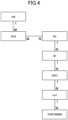
- FIG. 4 is a diagram for schematically illustrating an example of links between elements constructed in the communication system 1 in this embodiment.
- Symbols M and N indicated in FIG. 4 each represent any integer of 1 or more, and each indicate a relationship between the numbers of elements connected by a link.
- the link has a combination of M and N at both ends thereof, the elements connected by the link have a many-to-many relationship.
- the link has a combination of 1 and N or a combination of 1 and M at both ends thereof, the elements connected by the link have a one-to-many relationship.
- a network service (NS), a network function (NF), a containerized network function component (CNFC), a pod, and a container have a hierarchical structure.
- the NS corresponds to, for example, a network service formed of a plurality of NFs.
- the NS may correspond to an element having a granularity, such as a 5GC, an EPC, a 5G RAN (gNB), or a 4G RAN (eNB).
- the NF corresponds to an element having a granularity, such as the RU, the DU, the CU-UP, the AMF, the SMF, or the UPF.
- the NF corresponds to an element having a granularity, such as a mobility management entity (MME), a home subscriber server (HSS), a serving gateway (S-GW), a vDU, or a vCU.
- MME mobility management entity
- HSS home subscriber server
- S-GW serving gateway
- vDU vDU
- vCU vCU
- one NS includes one or a plurality of NFs. That is, one or a plurality of NFs are under the control of one NS.
- the CNFC corresponds to an element having a granularity, such as DU mgmt or DU processing.
- the CNFC may be a microservice deployed on a server as one or more containers.
- some CNFCs may be microservices that provide a part of the functions of the DU, the CU-CP, the CU-UP, and the like.
- Some CNFCs may be microservices that provide a part of the functions of the UPF, the AMF, the SMF, and the like.
- one NF includes one or a plurality of CNFCs. That is, one or a plurality of CNFCs are under the control of one NF.
- the pod refers to, for example, the minimum unit for managing a Docker container by Kubernetes.
- one CNFC includes one or a plurality of pods. That is, one or a plurality of pods are under the control of one CNFC.
- one pod includes one or a plurality of containers. That is, one or a plurality of containers are under the control of one pod.
- a network slice (NSI) and a network slice subnet instance (NSSI) have a hierarchical structure.
- the NSIs can be said to be end-to-end virtual circuits that span a plurality of domains (for example, from the RAN 32 to the core network system 34).
- Each NSI may be a slice for high-speed and high-capacity communication (for example, for enhanced mobile broadband (eMBB)), a slice for high-reliability and low-latency communication (for example, for ultra-reliable and low latency communications (URLLC)), or a slice for connecting a large quantity of terminals (for example, for massive machine type communication (mMTC)).
- the NSSIs can be said to be single domain virtual circuits dividing an NSI.
- Each NSSI may be a slice of a RAN domain, a slice of a transport domain such as a mobile back haul (MBH) domain, or a slice of a core network domain.
- MMH mobile back haul
- the NSSI and the NS generally have a many-to-many relationship.
- one NF can belong to one or a plurality of network slices.
- network slice selection assistance information including one or a plurality of pieces of sub-network slice selection assist information (S-NSSAI) can be set for one NF.
- the S-NSSAI is information associated with the network slice.
- the NF is not required to belong to the network slice.
- FIG. 5 is a functional block diagram for illustrating an example of functions implemented by the platform system 30 in this embodiment.
- the platform system 30 in this embodiment is not required to implement all the functions illustrated in FIG. 5 , and may implement functions other than those illustrated in FIG. 5 .
- the platform system 30 in this embodiment may include a plurality of container managers 78.
- a container management tool such as Kubernetes
- a package manager such as Helm
- Each of the plurality of container managers 78 may execute the construction of a container such as the deployment of the container for a server group (for example, Kubernetes cluster) associated with the container manager 78.
- the repository 80 stores, for example, a container image of a container included in a functional unit group (for example, NF group) that implements a network service.
- a functional unit group for example, NF group
- the inventory database 82 is a database in which inventory information is stored.
- the inventory information includes, for example, information on a server arranged in the RAN 32 or the core network system 34 and managed by the platform system 30.
- the inventory database 82 stores inventory data.
- the inventory data indicates the current statuses of the configuration of an element group included in the communication system 1 and the link between the elements.
- the inventory data indicates the status of resources managed by the platform system 30 (for example, resource usage status).
- the inventory data may be physical inventory data or may be logical inventory data. The physical inventory data and the logical inventory data are described later.
- FIG. 6 is a diagram for illustrating an example of the data structure of the physical inventory data.
- the physical inventory data illustrated in FIG. 6 is associated with one server.
- the physical inventory data illustrated in FIG. 6 includes, for example, a server ID, location data, building data, floor number data, rack data, specification data, network data, an operating container ID list, and a cluster ID.
- the server ID included in the physical inventory data is, for example, an identifier of the server associated with the physical inventory data.
- the building data included in the physical inventory data is, for example, data indicating a building (for example, a building name) in which the server associated with the physical inventory data is arranged.
- the network data included in the physical inventory data is, for example, data indicating information relating to a network of the server associated with the physical inventory data.
- the network data indicates, for example, an NIC included in the server, the number of ports included in the NIC, and a port ID of each of the ports.
- the operating container ID list included in the physical inventory data is, for example, data indicating information relating to one or a plurality of containers operating in the server associated with the physical inventory data.
- the operating container ID list indicates, for example, a list of identifiers (container IDs) of instances of the containers.
- the pod data indicates, for example, attributes such as an identifier of an instance of the pod and the type of the pod.
- the logical inventory data may also include container data indicating information relating to a container included in the pod.
- the container data indicates, for example, attributes such as a container ID of an instance of the container and the type of the container.
- data indicating various attributes such as the host name and the IP address may be included in the above-mentioned data included in the logical inventory data.
- the container data may include data indicating the IP address of a container corresponding to the container data.
- the NF data may include data indicating the IP address and the host name of an NF indicated by the NF data.
- the inventory database 82 can appropriately grasp the resource status in cooperation with the container manager 78. Then, the inventory database 82 appropriately updates the inventory data stored in the inventory database 82 based on the latest resource status.
- the inventory database 82 updates the inventory data stored in the inventory database 82 in accordance with execution of an action, such as construction of a new element included in the communication system 1, a change of a configuration of the elements included in the communication system 1, scaling of the elements included in the communication system 1, or replacement of the elements included in the communication system 1.
- an action such as construction of a new element included in the communication system 1, a change of a configuration of the elements included in the communication system 1, scaling of the elements included in the communication system 1, or replacement of the elements included in the communication system 1.
- the service catalog storage 64 stores service catalog data.
- the service catalog data may include, for example, service template data indicating the logic to be used by the life cycle manager 94 or the like.
- This service template data includes information required for constructing the network service.
- the service template data includes information defining the NS, the NF, and the CNFC and information indicating an NS-NF-CNFC correspondence relationship.
- the service template data contains a workflow script for constructing the network service.
- An NS descriptor is an example of the service template data.
- the NSD is associated with a network service, and indicates, for example, the types of a plurality of functional units (for example, a plurality of CNFs) included in the network service.
- the NSD may indicate the number of CNFs or other functional units included in the network service for each type thereof.
- the NSD may also indicate a file name of a CNFD described later, which relates to the CNF included in the network service.
- a CNF descriptor is an example of the above-mentioned service template data.
- the CNFD may indicate computer resources (for example, CPU, memory, and hard disk drive) required by the CNF.
- the CNFD may also indicate, for each of a plurality of containers included in the CNF, computer resources (such as CPU, memory, and hard disk drive) required by the container.
- the service catalog data may also include information to be used by the policy manager 90, the information relating to a threshold value (for example, threshold value for abnormality detection) to be compared to the calculated performance index value.
- a threshold value for example, threshold value for abnormality detection
- the performance index value is described later.
- the service catalog data may also include, for example, slice template data.
- the slice template includes information required for executing instantiation of the network slice, and includes, for example, the logic to be used by the slice manager 92.
- the slice template data includes information on a "generic network slice template” defined by the GSM Association (GSMA) ("GSM" is a trademark). Specifically, the slice template data includes network slice template data (NST), network slice subnet template data (NSST), and network service template data. The slice template data also includes information indicating the hierarchical structure of those elements which is illustrated in FIG. 4 .
- GSM GSM Association
- the life cycle manager 94 may execute, for example, the workflow script associated with the network service to be purchased in response to the purchase request. Then, the life cycle manager 94 may execute this workflow script, to thereby instruct the container manager 78 to deploy the container included in the new network service to be purchased. Then, the container manager 78 may acquire the container image of the container from the repository 80 and deploy a container corresponding to the container image in the server.
- the life cycle manager 94 executes, for example, scaling or replacement of the element included in the communication system 1.
- the life cycle manager 94 may output a container deployment instruction or deletion instruction to the container manager 78.
- the container manager 78 may execute, for example, a process for deploying a container or a process for deleting a container in accordance with the instruction.
- the life cycle manager 94 can execute such scaling and replacement that cannot be handled by Kubernetes of the container manager 78 or other tools.
- the life cycle manager 94 may also output an instruction to create a communication route to the SDN controller 74.
- the life cycle manager 94 presents, to the SDN controller 74, two IP addresses at both ends of a communication route to be created, and the SDN controller 74 creates a communication route connecting those two IP addresses to each other.
- the created communication route may be managed so as to be linked to those two IP addresses.
- the life cycle manager 94 may also output to the SDN controller 74 an instruction to create a communication route between two IP addresses linked to the two IP addresses.
- the slice manager 92 executes, for example, instantiation of a network slice.
- the slice manager 92 executes, for example, instantiation of a network slice by executing the logic indicated by the slice template stored in the service catalog storage 64.
- the slice manager 92 includes, for example, a network slice management function (NSMF) and a network slice sub-network management function (NSSMF) described in the third generation partnership project (3GPP) (trademark) specification "TS28 533.”
- the NSMF is a function for generating and managing network slices, and provides an NSI management service.
- the NSSMF is a function for generating and managing network slice subnets forming a part of a network slice, and provides an NSSI management service.
- the slice manager 92 may output to the configuration manager 76 a configuration management instruction related to the instantiation of the network slice. Then, the configuration manager 76 may execute configuration management such as settings in accordance with the configuration management instruction.
- the SDN controller 74 may change the maximum value of the bandwidth that can be used for communication between two IP addresses without constructing a network slice.
- the estimation process 108 and the queue 100 are linked in advance.
- FIG. 8 a case in which the estimation process 108 and the queue 100 are linked in a one-to-one relationship is illustrated, but the estimation process 108 and the queue 100 may be linked in a many-to-many relationship.
- the estimation process 108 acquires a predetermined number of most recent pieces of the performance index value data or the performance index value data of a most recent predetermined period including at least the latest performance index value data among the performance index value data stored in the queue 100.
- the first group aggregation process 104a associated with a certain specific gNB generates performance index value data related to the gNB by aggregating the metric data related to the elements included in the gNB (for example, elements under the control of the gNB).
- the estimation process 108 which acquires the performance index value data generated by the first group aggregation process 104a acquires 60 pieces of performance index value data including the latest performance index value data stored in the queue 100.
- the machine learning model may be, for example, an existing prediction model. Further, for example, the machine learning model may be a trained machine learning model in which supervised learning using a plurality of training data elements has been executed in advance. In this case, each of those plurality of training data elements may include, for example, for given time points different from each other, learning input data indicating the traffic amount in the gNB for 60 minutes until the time point and teacher data indicating the level of the network load (for example, traffic amount or latency) of the gNB from the time point until 20 minutes after the time point.
- learning input data indicating the traffic amount in the gNB for 60 minutes until the time point
- teacher data indicating the level of the network load (for example, traffic amount or latency) of the gNB from the time point until 20 minutes after the time point.
- estimation process 108 acquires a part of the performance index value data stored in the queue 100 as described above, and the estimation process 108 may acquire all the performance index value data stored in the queue 100.
- the estimation process 108 outputs estimation result data indicating the execution result (estimation result) of the estimation process to the prediction determination process 106b linked to the estimation process 108.
- the prediction determination process 106b then acquires the estimation result data, and then determines the status of the communication system 1 based on the acquired estimation result data.
- the queue 100 in this embodiment is linked to the aggregation process 104, the actual result determination process 106a, the prediction determination process 106b, and the estimation process 108.
- the data bus 68 generates a performance index value file including at least a part of the performance index value data stored in the queue 100 at a frequency lower than the frequency at which the AI 70 acquires the performance index value data.
- the data bus 68 may generate, at predetermined time intervals, a performance index value file including the performance index value data stored in the queue 100 after a previous timing of generation of the performance index value file.
- the time interval may or may not match the time (60 minutes in the above example) corresponding to the maximum number of pieces of performance index value data that is storable in the queues 100 included in the first queue group 102a.
- the data bus 68 may generate a file including all the performance index value data stored in the queue 100 in response to dequeuing of all the performance index value data included in the generated performance index value file. That is, the file including all the performance index value data stored in the queue 100 may be generated in response to the replacement of all the performance index value data stored in the queue 100.
- the oldest performance index value data stored in the queue 100 is dequeued. That is, the oldest performance index value data stored in the queue 100 is erased from the queue 100.
- the data bus 68 when four pieces of performance index value data are stored in a queue 100 included in the second queue group 102b, the data bus 68 generates a performance index value file in which those four pieces of performance index value data are consolidated into one file. The data bus 68 then outputs the generated performance index value file to the big-data platform 66.
- the data bus 68 dequeues all the performance index value data stored in the queue 100. That is, all the performance index value data stored in the queue 100 is erased from the queue 100.
- the process executed in response to the generation of the performance index value file is different for the queues 100 included in the first queue group 102a from that for the queues 100 included in the second queue group 102b.
- the queues 100 included in the second queue group 102b all the performance index value data stored in a queue 100 is erased from the queue 100 in response to the generation of the performance index value file.
- dequeuing in response to the generation of the performance index value file is not executed.
- the purchaser of the network service can select an option related to a monitoring setting when purchasing the network service.
- the purchaser of the network service can select any one of a low-level option, a medium-level option, and a high-level option.
- the queues 100 linked to the element and the aggregation processes 104 linked to the element are also generated.
- an actual result determination process 106a linked to the queue 100 is also generated.
- the policy manager 90 may refer to the inventory data to confirm an attribute of the element associated with the generated actual result determination process 106a.
- the policy manager 90 may then generate an actual result determination process 106a in which a workflow corresponding to the confirmed attribute is set. Further, the actual result determination process 106a may execute the determination process by executing the workflow set for the actual result determination process 106a.
- the actual result determination process 106a may determine whether or not scale-out is required based on the acquired performance index value data.
- the platform system 30 may execute scale-out of the element included in the communication system 1 in response to a determination that scale-out is required.
- the policy manager 90, the life cycle manager 94, the container manager 78, and the configuration manager 76 may cooperate with each other to execute scale-out.
- the scale-out of the DUs 42 or CU-UPs 44b included in a certain specific gNB may be executed based on the performance index value data related to the certain specific gNB in response to the determination that the scale-out is required.
- the actual result determination process 106a may determine whether or not the acquired performance index value data satisfies a predetermined first scale-out condition. In this case, it may be determined whether or not the performance index value indicated by the performance index value data exceeds a threshold value th1.
- This performance index value may be a value indicating the level of the network load, such as the traffic amount (throughput) or latency.
- scale-out of the elements included in the communication system 1 may be executed.
- the queues 100 linked to the element, the aggregation processes 104 linked to the element, and the actual result determination process 106a linked to the queue 100 are also generated.
- the AI 70 generates an estimation process 108 linked to the actual result determination process 106a
- the policy manager 90 generates a prediction determination process 106b linked to the actual result determination process 106a.
- the estimation process 108 and the prediction determination process 106b may be activated.
- instantiation of a trained machine learning model may also be executed.
- the estimation process 108 may then execute the estimation using the instantiated machine learning model.
- the prediction determination process 106b may execute a predetermined determination process based on the estimation result data output by the estimation process 108 linked to the prediction determination process 106b. For example, the prediction determination process 106b may determine whether or not scale-out is required based on the network load prediction result.
- the actual result determination process 106a may acquire the enqueued performance index value data
- the estimation process 108 may acquire, of the performance index value data stored in the queue 100, a predetermined number of most recent pieces of the performance index value data or the performance index value data of a most recent predetermined period including at least the enqueued performance index value data.
- the enqueued performance index value data may be acquired by both the actual result determination process 106a and the estimation process 108.
- the actual result determination process 106a may determine whether or not scale-out is required based on the acquired performance index value data.
- the estimation process 108 may generate estimation result data indicating the network load prediction result based on the acquired performance index value data. The estimation process 108 may then output the generated estimation result data to the prediction determination process 106b. The prediction determination process 106b may acquire the estimation result data.
Landscapes
- Engineering & Computer Science (AREA)
- Computer Networks & Wireless Communication (AREA)
- Signal Processing (AREA)
- Software Systems (AREA)
- Theoretical Computer Science (AREA)
- Computer Vision & Pattern Recognition (AREA)
- Evolutionary Computation (AREA)
- Medical Informatics (AREA)
- Data Mining & Analysis (AREA)
- Physics & Mathematics (AREA)
- Computing Systems (AREA)
- General Engineering & Computer Science (AREA)
- General Physics & Mathematics (AREA)
- Mathematical Physics (AREA)
- Artificial Intelligence (AREA)
- Data Exchanges In Wide-Area Networks (AREA)
Applications Claiming Priority (1)
| Application Number | Priority Date | Filing Date | Title |
|---|---|---|---|
| PCT/JP2022/032682 WO2024047775A1 (ja) | 2022-08-30 | 2022-08-30 | 通信システムに係る所与の予測目的で用いられる機械学習モデルの決定 |
Publications (2)
| Publication Number | Publication Date |
|---|---|
| EP4583017A1 true EP4583017A1 (de) | 2025-07-09 |
| EP4583017A4 EP4583017A4 (de) | 2025-10-29 |
Family
ID=90098900
Family Applications (1)
| Application Number | Title | Priority Date | Filing Date |
|---|---|---|---|
| EP22957374.6A Pending EP4583017A4 (de) | 2022-08-30 | 2022-08-30 | Bestimmung eines maschinenlernmodells zur verwendung für gegebenen prädiktiven zweck für ein kommunikationssystem |
Country Status (4)
| Country | Link |
|---|---|
| US (1) | US20250097721A1 (de) |
| EP (1) | EP4583017A4 (de) |
| JP (1) | JP7716598B2 (de) |
| WO (1) | WO2024047775A1 (de) |
Families Citing this family (1)
| Publication number | Priority date | Publication date | Assignee | Title |
|---|---|---|---|---|
| JP7820561B2 (ja) * | 2022-11-21 | 2026-02-25 | 楽天モバイル株式会社 | 通信システムに含まれる要素に対するアクションを実行するか否かを判定する判定処理の実行開始制御 |
Family Cites Families (19)
| Publication number | Priority date | Publication date | Assignee | Title |
|---|---|---|---|---|
| JP4230975B2 (ja) * | 2004-09-17 | 2009-02-25 | キヤノンItソリューションズ株式会社 | データ予測装置及びデータ予測方法並びにプログラム |
| US10769549B2 (en) * | 2016-11-21 | 2020-09-08 | Google Llc | Management and evaluation of machine-learned models based on locally logged data |
| JP6751069B2 (ja) | 2017-11-16 | 2020-09-02 | 日本電信電話株式会社 | 無線リソース設計装置、無線リソース設計方法、及びプログラム |
| US11645541B2 (en) * | 2017-11-17 | 2023-05-09 | Adobe Inc. | Machine learning model interpretation |
| US12117997B2 (en) * | 2018-05-22 | 2024-10-15 | Data.World, Inc. | Auxiliary query commands to deploy predictive data models for queries in a networked computing platform |
| US11537990B2 (en) * | 2018-05-22 | 2022-12-27 | Data.World, Inc. | Computerized tools to collaboratively generate queries to access in-situ predictive data models in a networked computing platform |
| JP7267964B2 (ja) * | 2019-03-14 | 2023-05-02 | アクタピオ,インコーポレイテッド | 生成装置、生成方法および生成プログラム |
| US11392803B2 (en) * | 2019-06-04 | 2022-07-19 | International Business Machines Corporation | Decision boundary enhancement for learning models |
| US20230267786A1 (en) * | 2019-09-17 | 2023-08-24 | Smiota, Inc. | Unifying smart locker agnostic operating platform |
| CN112825576B (zh) * | 2019-11-20 | 2023-05-05 | 中国电信股份有限公司 | 小区扩容的确定方法、装置以及存储介质 |
| JP7413742B2 (ja) * | 2019-12-05 | 2024-01-16 | オムロン株式会社 | 予測システム、情報処理装置および情報処理プログラム |
| WO2021171341A1 (ja) * | 2020-02-25 | 2021-09-02 | 日本電信電話株式会社 | 通信品質を予測するシステム、装置、方法及びプログラム |
| US11501190B2 (en) * | 2020-07-02 | 2022-11-15 | Juniper Networks, Inc. | Machine learning pipeline for predictions regarding a network |
| US12149417B2 (en) * | 2021-07-14 | 2024-11-19 | Hughes Network Systems, Llc | Efficient maintenance for communication devices |
| US11934455B2 (en) * | 2021-08-31 | 2024-03-19 | Comcast Cable Communications, Llc | Systems, methods, and apparatuses for audience metric determination |
| US12425673B2 (en) * | 2021-11-02 | 2025-09-23 | Comcast Cable Communications, Llc | Systems, methods, and apparatuses for device location |
| US12379983B2 (en) * | 2021-11-19 | 2025-08-05 | Microsoft Technology Licensing, Llc | Training and using a memory failure prediction model |
| MX2024008034A (es) * | 2021-12-30 | 2024-07-15 | Assurant Inc | Sistema, metodo y producto de programa de computadora para la deteccion de fallas en dispositivos indicadores de ubicacion. |
| US11785591B2 (en) * | 2022-04-04 | 2023-10-10 | Ultralogic 6G, Llc | Multiplexed code for ACK/SR/power/beam feedback in 5G and 6G |
-
2022
- 2022-08-30 EP EP22957374.6A patent/EP4583017A4/de active Pending
- 2022-08-30 US US18/570,635 patent/US20250097721A1/en active Pending
- 2022-08-30 WO PCT/JP2022/032682 patent/WO2024047775A1/ja not_active Ceased
- 2022-08-30 JP JP2024543675A patent/JP7716598B2/ja active Active
Also Published As
| Publication number | Publication date |
|---|---|
| US20250097721A1 (en) | 2025-03-20 |
| WO2024047775A1 (ja) | 2024-03-07 |
| JP7716598B2 (ja) | 2025-07-31 |
| JPWO2024047775A1 (de) | 2024-03-07 |
| EP4583017A4 (de) | 2025-10-29 |
Similar Documents
| Publication | Publication Date | Title |
|---|---|---|
| EP4583016A1 (de) | Bestimmung eines maschinenlernmodells für gegebenen prädiktiven zweck in bezug auf ein kommunikationssystem | |
| EP4625177A1 (de) | Steuerung der ausführungsbedingung für aktion bezüglich eines in einem kommunikationssystem enthaltenen elements | |
| US12531791B2 (en) | Validation system and validation method | |
| US20240248763A1 (en) | Arrangement system and arrangement method | |
| US20250094309A1 (en) | Display control of monitoring screens showing performance index values of elements included in communication system | |
| US20250097091A1 (en) | Execution initiation control of determination process to determine whether or not to execute action on element included in communication system | |
| US12255784B2 (en) | Controlling start timing of network load prediction | |
| EP4583017A1 (de) | Bestimmung eines maschinenlernmodells zur verwendung für gegebenen prädiktiven zweck für ein kommunikationssystem | |
| US20240281301A1 (en) | Execution platform determination system and execution platform determination method | |
| US12279124B2 (en) | Executing appropriate scale-out of an element included in a communication system | |
| US12520194B2 (en) | Executing appropriate scale-out of an element included in a communication system | |
| US20240414571A1 (en) | Status determination of a communication system based on performance index value data stored in a queue | |
| EP4564769A1 (de) | Steuerung des timings zur startvorhersage einer netzwerklast | |
| US20250103376A1 (en) | Determining whether process included in communication system is unstable | |
| US20250103353A1 (en) | Replacement of unstable application | |
| US20250103469A1 (en) | Estimating cause of application instability | |
| EP4694541A1 (de) | Schätzung eines routers, der stillen ausfall verursacht | |
| US20250094226A1 (en) | Management of hardware resources included in a communication system | |
| US20250094227A1 (en) | Management of hardware resources included in a communication system | |
| US20240272895A1 (en) | Replace system and replace method | |
| EP4694051A1 (de) | Schätzung eines routers als ursprung eines stillen ausfalls |
Legal Events
| Date | Code | Title | Description |
|---|---|---|---|
| STAA | Information on the status of an ep patent application or granted ep patent |
Free format text: STATUS: THE INTERNATIONAL PUBLICATION HAS BEEN MADE |
|
| PUAI | Public reference made under article 153(3) epc to a published international application that has entered the european phase |
Free format text: ORIGINAL CODE: 0009012 |
|
| STAA | Information on the status of an ep patent application or granted ep patent |
Free format text: STATUS: REQUEST FOR EXAMINATION WAS MADE |
|
| 17P | Request for examination filed |
Effective date: 20250331 |
|
| AK | Designated contracting states |
Kind code of ref document: A1 Designated state(s): AL AT BE BG CH CY CZ DE DK EE ES FI FR GB GR HR HU IE IS IT LI LT LU LV MC MK MT NL NO PL PT RO RS SE SI SK SM TR |
|
| A4 | Supplementary search report drawn up and despatched |
Effective date: 20250930 |
|
| RIC1 | Information provided on ipc code assigned before grant |
Ipc: G06N 20/00 20190101AFI20250924BHEP Ipc: H04W 24/02 20090101ALI20250924BHEP Ipc: H04W 16/22 20090101ALI20250924BHEP Ipc: H04W 24/08 20090101ALI20250924BHEP |
|
| DAV | Request for validation of the european patent (deleted) | ||
| DAX | Request for extension of the european patent (deleted) |