EP4582906A1 - Verfahren zur anzeige von objekten der erweiterten realität und elektronische vorrichtung zur unterstützung davon - Google Patents
Verfahren zur anzeige von objekten der erweiterten realität und elektronische vorrichtung zur unterstützung davon Download PDFInfo
- Publication number
- EP4582906A1 EP4582906A1 EP23872894.3A EP23872894A EP4582906A1 EP 4582906 A1 EP4582906 A1 EP 4582906A1 EP 23872894 A EP23872894 A EP 23872894A EP 4582906 A1 EP4582906 A1 EP 4582906A1
- Authority
- EP
- European Patent Office
- Prior art keywords
- display
- pixel value
- representative pixel
- processor
- section
- Prior art date
- Legal status (The legal status is an assumption and is not a legal conclusion. Google has not performed a legal analysis and makes no representation as to the accuracy of the status listed.)
- Pending
Links
Images


Classifications
-
- G—PHYSICS
- G06—COMPUTING OR CALCULATING; COUNTING
- G06T—IMAGE DATA PROCESSING OR GENERATION, IN GENERAL
- G06T19/00—Manipulating three-dimensional [3D] models or images for computer graphics
- G06T19/006—Mixed reality
-
- G—PHYSICS
- G02—OPTICS
- G02B—OPTICAL ELEMENTS, SYSTEMS OR APPARATUS
- G02B27/00—Optical systems or apparatus not provided for by any of the groups G02B1/00 - G02B26/00, G02B30/00
- G02B27/01—Head-up displays
- G02B27/017—Head mounted
-
- G—PHYSICS
- G06—COMPUTING OR CALCULATING; COUNTING
- G06F—ELECTRIC DIGITAL DATA PROCESSING
- G06F1/00—Details not covered by groups G06F3/00 - G06F13/00 and G06F21/00
- G06F1/16—Constructional details or arrangements
- G06F1/1613—Constructional details or arrangements for portable computers
- G06F1/163—Wearable computers, e.g. on a belt
-
- G—PHYSICS
- G06—COMPUTING OR CALCULATING; COUNTING
- G06F—ELECTRIC DIGITAL DATA PROCESSING
- G06F1/00—Details not covered by groups G06F3/00 - G06F13/00 and G06F21/00
- G06F1/16—Constructional details or arrangements
- G06F1/1613—Constructional details or arrangements for portable computers
- G06F1/1633—Constructional details or arrangements of portable computers not specific to the type of enclosures covered by groups G06F1/1615 - G06F1/1626
- G06F1/1656—Details related to functional adaptations of the enclosure, e.g. to provide protection against EMI, shock, water, or to host detachable peripherals like a mouse or removable expansions units like PCMCIA cards, or to provide access to internal components for maintenance or to removable storage supports like CDs or DVDs, or to mechanically mount accessories
- G06F1/1658—Details related to functional adaptations of the enclosure, e.g. to provide protection against EMI, shock, water, or to host detachable peripherals like a mouse or removable expansions units like PCMCIA cards, or to provide access to internal components for maintenance or to removable storage supports like CDs or DVDs, or to mechanically mount accessories related to the mounting of internal components, e.g. disc drive or any other functional module
-
- G—PHYSICS
- G06—COMPUTING OR CALCULATING; COUNTING
- G06F—ELECTRIC DIGITAL DATA PROCESSING
- G06F3/00—Input arrangements for transferring data to be processed into a form capable of being handled by the computer; Output arrangements for transferring data from processing unit to output unit, e.g. interface arrangements
- G06F3/01—Input arrangements or combined input and output arrangements for interaction between user and computer
- G06F3/011—Arrangements for interaction with the human body, e.g. for user immersion in virtual reality
-
- G—PHYSICS
- G06—COMPUTING OR CALCULATING; COUNTING
- G06F—ELECTRIC DIGITAL DATA PROCESSING
- G06F3/00—Input arrangements for transferring data to be processed into a form capable of being handled by the computer; Output arrangements for transferring data from processing unit to output unit, e.g. interface arrangements
- G06F3/01—Input arrangements or combined input and output arrangements for interaction between user and computer
- G06F3/048—Interaction techniques based on graphical user interfaces [GUI]
- G06F3/0481—Interaction techniques based on graphical user interfaces [GUI] based on specific properties of the displayed interaction object or a metaphor-based environment, e.g. interaction with desktop elements like windows or icons, or assisted by a cursor's changing behaviour or appearance
- G06F3/0482—Interaction with lists of selectable items, e.g. menus
-
- G—PHYSICS
- G06—COMPUTING OR CALCULATING; COUNTING
- G06F—ELECTRIC DIGITAL DATA PROCESSING
- G06F3/00—Input arrangements for transferring data to be processed into a form capable of being handled by the computer; Output arrangements for transferring data from processing unit to output unit, e.g. interface arrangements
- G06F3/01—Input arrangements or combined input and output arrangements for interaction between user and computer
- G06F3/048—Interaction techniques based on graphical user interfaces [GUI]
- G06F3/0484—Interaction techniques based on graphical user interfaces [GUI] for the control of specific functions or operations, e.g. selecting or manipulating an object, an image or a displayed text element, setting a parameter value or selecting a range
- G06F3/04842—Selection of displayed objects or displayed text elements
-
- G—PHYSICS
- G06—COMPUTING OR CALCULATING; COUNTING
- G06T—IMAGE DATA PROCESSING OR GENERATION, IN GENERAL
- G06T7/00—Image analysis
- G06T7/10—Segmentation; Edge detection
- G06T7/11—Region-based segmentation
-
- G—PHYSICS
- G02—OPTICS
- G02B—OPTICAL ELEMENTS, SYSTEMS OR APPARATUS
- G02B27/00—Optical systems or apparatus not provided for by any of the groups G02B1/00 - G02B26/00, G02B30/00
- G02B27/01—Head-up displays
- G02B27/0101—Head-up displays characterised by optical features
- G02B2027/0138—Head-up displays characterised by optical features comprising image capture systems, e.g. camera
-
- G—PHYSICS
- G06—COMPUTING OR CALCULATING; COUNTING
- G06T—IMAGE DATA PROCESSING OR GENERATION, IN GENERAL
- G06T2200/00—Indexing scheme for image data processing or generation, in general
- G06T2200/16—Indexing scheme for image data processing or generation, in general involving adaptation to the client's capabilities
Definitions
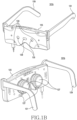
- the display may be disposed to an inner space of a main frame 125 and thus at least part thereof may be exposed to the outside and may be visible through the lens 127.
- the display may include a liquid crystal display device, a digital mirror display device, or a silicon liquid crystal display device, and in this case, the electronic device 101b may include a light source which irradiates light to a screen output region of the display.
- the display may include an organic light emitting diode device or micro organic light emitting diode device capable of generating light autonomously, and in this case, the electronic device 101b may not include a separate light source.
- the lens 127 may adjust a focus so that a screen which is output through the display is visible on a user's watch.
- a lens assembly including at least one lens may be disposed in an inner space of the main frame 125 at positions corresponding to user's left and right eyes.
- at least part of the lens 127 may be exposed to the outside through an inner face of the main frame 125 so that the user is able to see a screen output by the display.
- the electronic device 101b may use the at least one first camera 133 to perform at least one of 3Dof or 6Dof head tracking, hand tracking, and space recognition.
- the electronic device 101b may use the at least one first camera 133 to execute at least one of a space recognition function, a Simultaneous Localization and Mapping (SLAM) function for depth shooting, and a user gesture recognition function.
- the electronic device 101b may acquire (or capture) an image for an external environment (e.g., a scene of a real world) by using the at least one second camera 135.
- the at least one second camera 135 may include a color camera capable of executing, for example, at least one of an auto-focus function and a shaking-correction function.
- At least one front camera 231 may be disposed to the front face of the electronic device 101c.
- the at least one front camera 231 may be disposed below the display 210, and at least part thereof may be exposed to the outside through one region of the display 210.
- the at least one front camera 231 may include a first front camera and a second front camera.
- the first front camera and the second front camera may be the same-type of cameras having the same specification (e.g., a pixel and/or a field of view), but may be implemented with cameras of different specifications.
- the electronic device 101c may support a function (e.g., 3D shooting and/or auto focus) related to a dual camera by using the first front camera and the second front camera.
- At least one camera among the first rear camera, the second rear camera, and the third rear camera may differ from the other cameras in at least one of a field of view, a pixel, an aperture, whether to support an optical zoom function, whether to support a digital zoom function, whether to support an optical image stabilizer function, a type of a lens assembly, and an array of the lens assembly.
- the first rear camera may be a general camera.
- the second rear camera may be a camera which supports wide shooting.
- the third camera may be a camera which supports telephoto shooting.
- a hardware component which assists image capturing may be further disposed to the camera region 230 of the electronic device 101c.
- at least one flash 235 for providing a light source may be disposed to the camera region 230.
- at least one sensor e.g., a time-of-flight sensor, a depth sensor, a range sensor, a laser sensor, a photo diode pixel, and/or a stereo camera
- a distance between a subject and the electronic device 101c may be disposed to the camera region 230.
- the electronic device 101a of FIG. 1a , the electronic device 101b of FIG. 1b , or the electronic device 101c of FIG. 2 may omit at least one of the aforementioned components, or may further include an additional component.
- the electronic device 101a, 101b, or 101c (hereinafter, referred to as an electronic device 101) may correspond to an electronic device to be described with reference to FIG. 9 (e.g., an electronic device 901 of FIG. 9 ), and may further include at least some of the components included in the electronic device 901 of FIG. 9 .
- the at least one of cameras 133, 135, and/or 137 included in the electronic device 101b of FIG. 1b , or the at least one of cameras 231 and/or 233 included in the electronic device 101c of FIG. 2 may correspond to a camera module 980 included in the electronic device 901 of FIG. 9 .
- the displays 103-L and/or 103-R included in the electronic device 101a of FIG. 1a , a display (not shown) included in the electronic device 101b of FIG. 1b , or the display 210 included in the electronic device 101c of FIG. 2 may correspond to a display module 960 included in the electronic device 901 of FIG. 9 .
- the electronic device 101 may include at least one processing circuit electrically coupled to at least one camera (e.g., the camera module 980) and the display (e.g., the display module 960).
- the electronic device 101 may include at least one of an application processor (e.g., a main processor 921 of FIG. 9 ), a communication processor (e.g., an auxiliary processor 923 of FIG. 9 ), an image signal processor included in the camera module 980, and a display driver integrated circuit included in the display module 960.
- the at least one processing circuit included in the electronic device 101 may be collectively referred to as a processor.
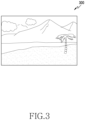
- FIG. 3 illustrates an image acquired by using a camera according to an embodiment.
- a processor e.g., a processor 902 of FIG. 9 of the electronic device 101 may acquire (or capture) an image 300 by using at least one camera (e.g., the camera module 980 of FIG. 9 ).
- the processor may execute an application supporting an image capture function and/or the at least one camera to acquire the image 300 presenting an external environment (e.g., a scene of a real world) in front of the at least one camera.
- the processor of the electronic device 101 may not display the acquired image 300 through a display (e.g., the display module 960 of FIG. 9 ).
- the image 300 may be stored in a memory (e.g., a memory 930 of FIG. 9 ), and an external environment (e.g., a scene of a real world) may be viewed through the display of the electronic device 101, transparent members (e.g., the first transparent member 123-L and second transparent member 123-R of FIG. 1 ), and/or a lens (e.g., the lens 127 of FIG. 1b ).
- the processor of the electronic device 101 may display the acquired image 300 through the display on a real-time basis.
- the processor may store the acquired image 300 in the memory, and may display it as a preview image through the display.
- a position of the external environment corresponding to the acquired image 300 or at least one object (e.g., a thing, a person, and/or a building) included in the image 300 may be related to at least one AR object (or AR content) for providing an AR environment or an MR environment to a user who wears or owns the electronic device 101.
- at least one AR object or AR content
- FIG. 4 illustrates an AR object to be displayed by using a display according to an embodiment.
- a processor e.g., a processor 920 of FIG. 9
- the electronic device 101 may identify at least one of AR objects 410, 420, and/or 430 to be displayed by using a display (e.g., the display module 960 of FIG. 9 ), based on that an image (e.g., the image 300 of FIG. 3 ) is acquired by using at least one camera (e.g., the camera module 980 of FIG. 9 ).
- the processor may divide each of the at least one of AR objects 410, 420, and/or 430 into at least one section (or region), based on an outline (or a border) corresponding to each design or shape of the at least one of AR objects 410, 420, and/or 430.
- the first AR object 410 may be divided into a first section 413 defined by a first outline 413a and a second section 411 excluding a portion overlaid with a different section (e.g., the first section 413) among sections defined by a second outline 411a.
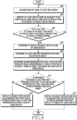
- the processor may identify at least one of a count of the at least one of AR objects 410, 420, and/or 430 to be displayed by using the display and a ratio of a display area of the at least one of AR objects 410, 420, and/or 430. For example, the processor may determine a total count of the at least one of AR objects 410, 420, and/or 430 by adding up the count of the at least one of AR objects 410, 420, and/or 430 to be displayed.
- the processor may determine the ratio of the display area of the at least one of AR objects 410, 420, and/or 430 by comparing a display area occupied by the at least one of AR objects 410, 420, and/or 430 with respect to a resolution of the display (or a size of a display region).
- the display area of the at least one of AR objects 410, 420, and/or 430 may be referred to as an extent (or a size, or the number of pixels) defined by an outermost outline (e.g., the second outline 411a) of a corresponding AR object (e.g., the first AR object 410).
- the processor may compare a value obtained by adding up the display area of each of the at least one of AR objects 410, 420, and/or 430 with a resolution value of the display to determine the ratio of the display area of the at least one of AR objects 410, 420, and/or 430.
- the processor may compare the count identified for the at least one of AR objects 410, 420, and/or 430 to be displayed by using the display and/or the ratio of the display area with a predetermined first threshold. For example, the processor may compare the count of the at least one of AR objects 410, 420, and/or 430 with a predetermined threshold count (e.g., 5). In addition, for example, the processor may compare the ratio of the display area of the at least one of AR objects 410, 420, and/or 430 with a predetermined threshold ratio (e.g., 20% against the resolution of the display).
- a predetermined threshold count e.g., 5
- the processor may compare the ratio of the display area of the at least one of AR objects 410, 420, and/or 430 with a predetermined threshold ratio (e.g., 20% against the resolution of the display).
- the processor may determine whether to display the at least one of AR objects 410, 420, and/or 430 as an outline by using the display.
- the processor may determine to display the at least one of AR objects 410, 420, and/or 430 as the outline.
- the processor may determine not to display the at least one of AR objects 410, 420, and/or 430 as the outline (or may determine to display it with an original image of the AR object).
- the processor may determine at least one first representative pixel value for each of the at least one of AR objects 410, 420, and/or 430. For example, the processor may determine the first representative pixel value for each of the at least one section divided for each of the at least one of AR objects 410, 420, and/or 430.
- the processor may determine each of a representative pixel value for a first section 431 of the second AR object 430, a representative pixel value for a second section 433, a representative pixel value for a third section 435, and a representative pixel value for a fourth section 437.
- the processor may determine a representative pixel value for at least one section of each of the at least one of AR objects 410, 420, and/or 430. Taking the first section 431 of the second AR object 430 for example, the processor may determine a representative pixel value of the first section 431 as a representative value (e.g., an RGB value with highest weight) or average value of RGB values for presenting the first section 431 when displaying the second AR object 430 by using the display.
- a representative value of the first section 431 e.g., an RGB value with highest weight
- the processor may determine the representative pixel value for the first section 431 of the second AR object 430 as a YCbCr value converted by dividing the representative value or average value of the RGB values into a luminance component and a chrominance component.
- the representative pixel value determined for each of the at least one section of the AR object may be similar to or different from each other at least in part according to a color for presenting each of the at least one section.
- the representative pixel value determined for each of the sections 431 and 435 may be identical or similar.
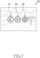
- FIG. 5 illustrates one region of an image corresponding to a display position of an AR object according to an embodiment.
- a processor e.g., the processor 920 of FIG. 9 ) of the electronic device 101 according to an embodiment may determine a second representative pixel value for the image 300 acquired through at least one camera (e.g., the camera module 980 of FIG. 9 ). For example, when displaying the at least one of AR objects 410, 420, and/or 430 and the image 300 by using a display (e.g., the display module 960 of FIG.
Landscapes
- Engineering & Computer Science (AREA)
- Theoretical Computer Science (AREA)
- General Engineering & Computer Science (AREA)
- Physics & Mathematics (AREA)
- General Physics & Mathematics (AREA)
- Computer Hardware Design (AREA)
- Human Computer Interaction (AREA)
- Computer Graphics (AREA)
- Software Systems (AREA)
- Optics & Photonics (AREA)
- Computer Vision & Pattern Recognition (AREA)
- Studio Devices (AREA)
- Processing Or Creating Images (AREA)
Applications Claiming Priority (3)
| Application Number | Priority Date | Filing Date | Title |
|---|---|---|---|
| KR20220121312 | 2022-09-26 | ||
| KR1020220135082A KR20240043025A (ko) | 2022-09-26 | 2022-10-19 | 증강 현실 객체 표시 방법 및 이를 지원하는 전자 장치 |
| PCT/KR2023/013959 WO2024071776A1 (ko) | 2022-09-26 | 2023-09-15 | 증강 현실 객체 표시 방법 및 이를 지원하는 전자 장치 |
Publications (2)
| Publication Number | Publication Date |
|---|---|
| EP4582906A1 true EP4582906A1 (de) | 2025-07-09 |
| EP4582906A4 EP4582906A4 (de) | 2025-12-10 |
Family
ID=90478404
Family Applications (1)
| Application Number | Title | Priority Date | Filing Date |
|---|---|---|---|
| EP23872894.3A Pending EP4582906A4 (de) | 2022-09-26 | 2023-09-15 | Verfahren zur anzeige von objekten der erweiterten realität und elektronische vorrichtung zur unterstützung davon |
Country Status (3)
| Country | Link |
|---|---|
| US (1) | US20250225744A1 (de) |
| EP (1) | EP4582906A4 (de) |
| WO (1) | WO2024071776A1 (de) |
Family Cites Families (9)
| Publication number | Priority date | Publication date | Assignee | Title |
|---|---|---|---|---|
| KR100860940B1 (ko) * | 2007-01-22 | 2008-09-29 | 광주과학기술원 | 컬러 마커를 이용한 컨텐츠 제공 방법 및 이를 수행하기 위한 시스템 |
| KR101266198B1 (ko) * | 2010-10-19 | 2013-05-21 | 주식회사 팬택 | 증강현실 객체정보의 가시성을 높이는 디스플레이 장치 및 디스플레이 방법 |
| KR102393299B1 (ko) * | 2017-08-09 | 2022-05-02 | 삼성전자주식회사 | 이미지 처리 방법 및 그에 따른 장치 |
| KR102045748B1 (ko) * | 2017-12-11 | 2019-11-18 | 주식회사 한글과컴퓨터 | Vr 기반의 프레젠테이션 문서의 출력이 가능한 hmd 장치 및 그 동작 방법 |
| US10728430B2 (en) * | 2018-03-07 | 2020-07-28 | Disney Enterprises, Inc. | Systems and methods for displaying object features via an AR device |
| TWI675583B (zh) * | 2018-07-23 | 2019-10-21 | 緯創資通股份有限公司 | 擴增實境系統及其色彩補償方法 |
| JP2020017006A (ja) * | 2018-07-24 | 2020-01-30 | 日本精機株式会社 | 車両用拡張現実画像表示装置 |
| US11423621B1 (en) * | 2020-05-21 | 2022-08-23 | Facebook Technologies, Llc. | Adaptive rendering in artificial reality environments |
| US11847258B2 (en) * | 2020-11-17 | 2023-12-19 | Samsung Electronics Co., Ltd. | Method for wireless connection in augmented reality environment and electronic device therefor |
-
2023
- 2023-09-15 EP EP23872894.3A patent/EP4582906A4/de active Pending
- 2023-09-15 WO PCT/KR2023/013959 patent/WO2024071776A1/ko not_active Ceased
-
2025
- 2025-03-25 US US19/089,802 patent/US20250225744A1/en active Pending
Also Published As
| Publication number | Publication date |
|---|---|
| WO2024071776A1 (ko) | 2024-04-04 |
| US20250225744A1 (en) | 2025-07-10 |
| EP4582906A4 (de) | 2025-12-10 |
Similar Documents
| Publication | Publication Date | Title |
|---|---|---|
| US11852820B2 (en) | Method and electronic device for changing setting of display | |
| US12561926B2 (en) | Electronic device and method for displaying notification about external object | |
| US11733952B2 (en) | Wearable electronic device including display, method for controlling display, and system including wearable electronic device and case | |
| KR102917803B1 (ko) | 디스플레이의 설정 변경 방법 및 전자 장치 | |
| EP4235363A1 (de) | Elektronische vorrichtung mit flexibler anzeige, betriebsverfahren dafür und speichermedium | |
| US20230005227A1 (en) | Electronic device and method for offering virtual reality service | |
| US12276800B2 (en) | Wearable device for adjusting light transmittance according to illuminance of external light source, and method for controlling same | |
| EP4357838B1 (de) | Elektronische vorrichtung und verfahren zur anzeige von inhalt | |
| US20250254435A1 (en) | Wearable electronic device including camera and operation method thereof | |
| US12457415B2 (en) | Method for executing application, and electronic device supporting same | |
| US12348856B2 (en) | Method and device for obtaining image of object | |
| EP4582906A1 (de) | Verfahren zur anzeige von objekten der erweiterten realität und elektronische vorrichtung zur unterstützung davon | |
| US11893698B2 (en) | Electronic device, AR device and method for controlling data transfer interval thereof | |
| US12613576B2 (en) | Wearable device providing immersive experience and method of controlling same | |
| US12506859B2 (en) | Wearable electronic device comprising sensor and operation method thereof | |
| KR20240043025A (ko) | 증강 현실 객체 표시 방법 및 이를 지원하는 전자 장치 | |
| US12541251B2 (en) | Wearable device and method for identifying location of target object | |
| US12456164B2 (en) | Electronic device for controlling resolution of each of plurality of areas included in image acquired from camera and method thereof | |
| US20250199612A1 (en) | Wearable device providing immersive experience and method of controlling same | |
| US20250166537A1 (en) | Wearable electronic device and operation method thereof | |
| US20250216683A1 (en) | Wearable device for guiding user's posture and method thereof | |
| KR102940216B1 (ko) | 전자 장치 및 가상 객체 선택 방법 | |
| US20250224801A1 (en) | Electronic device for supporting augmented reality function and operating method thereof | |
| US20250173919A1 (en) | Device and method for measuring distance with respect to external object | |
| US20240046530A1 (en) | Method of controlling display module, and electronic device performing the method |
Legal Events
| Date | Code | Title | Description |
|---|---|---|---|
| STAA | Information on the status of an ep patent application or granted ep patent |
Free format text: STATUS: THE INTERNATIONAL PUBLICATION HAS BEEN MADE |
|
| PUAI | Public reference made under article 153(3) epc to a published international application that has entered the european phase |
Free format text: ORIGINAL CODE: 0009012 |
|
| STAA | Information on the status of an ep patent application or granted ep patent |
Free format text: STATUS: REQUEST FOR EXAMINATION WAS MADE |
|
| 17P | Request for examination filed |
Effective date: 20250403 |
|
| AK | Designated contracting states |
Kind code of ref document: A1 Designated state(s): AL AT BE BG CH CY CZ DE DK EE ES FI FR GB GR HR HU IE IS IT LI LT LU LV MC ME MK MT NL NO PL PT RO RS SE SI SK SM TR |
|
| A4 | Supplementary search report drawn up and despatched |
Effective date: 20251110 |
|
| RIC1 | Information provided on ipc code assigned before grant |
Ipc: G06F 3/01 20060101AFI20251104BHEP Ipc: G06T 19/00 20110101ALI20251104BHEP Ipc: G06T 3/40 20240101ALI20251104BHEP Ipc: G06F 3/00 20060101ALI20251104BHEP Ipc: G06F 3/04817 20220101ALI20251104BHEP Ipc: G06F 3/04842 20220101ALI20251104BHEP Ipc: G06F 1/16 20060101ALI20251104BHEP Ipc: G06F 3/0482 20130101ALI20251104BHEP Ipc: G06F 3/0484 20220101ALI20251104BHEP |
|
| DAV | Request for validation of the european patent (deleted) | ||
| DAX | Request for extension of the european patent (deleted) | ||
| GRAP | Despatch of communication of intention to grant a patent |
Free format text: ORIGINAL CODE: EPIDOSNIGR1 |
|
| STAA | Information on the status of an ep patent application or granted ep patent |
Free format text: STATUS: GRANT OF PATENT IS INTENDED |
|
| INTG | Intention to grant announced |
Effective date: 20260130 |
|
| GRAS | Grant fee paid |
Free format text: ORIGINAL CODE: EPIDOSNIGR3 |
|
| GRAA | (expected) grant |
Free format text: ORIGINAL CODE: 0009210 |
|
| STAA | Information on the status of an ep patent application or granted ep patent |
Free format text: STATUS: THE PATENT HAS BEEN GRANTED |