EP4582878A2 - Cartridge and image forming apparatus - Google Patents
Cartridge and image forming apparatus Download PDFInfo
- Publication number
- EP4582878A2 EP4582878A2 EP25171868.0A EP25171868A EP4582878A2 EP 4582878 A2 EP4582878 A2 EP 4582878A2 EP 25171868 A EP25171868 A EP 25171868A EP 4582878 A2 EP4582878 A2 EP 4582878A2
- Authority
- EP
- European Patent Office
- Prior art keywords
- cartridge
- section
- contact
- electrode
- resin material
- Prior art date
- Legal status (The legal status is an assumption and is not a legal conclusion. Google has not performed a legal analysis and makes no representation as to the accuracy of the status listed.)
- Pending
Links
Images













Classifications
-
- G—PHYSICS
- G03—PHOTOGRAPHY; CINEMATOGRAPHY; ANALOGOUS TECHNIQUES USING WAVES OTHER THAN OPTICAL WAVES; ELECTROGRAPHY; HOLOGRAPHY
- G03G—ELECTROGRAPHY; ELECTROPHOTOGRAPHY; MAGNETOGRAPHY
- G03G21/00—Arrangements not provided for by groups G03G13/00 - G03G19/00, e.g. cleaning, elimination of residual charge
- G03G21/16—Mechanical means for facilitating the maintenance of the apparatus, e.g. modular arrangements
- G03G21/18—Mechanical means for facilitating the maintenance of the apparatus, e.g. modular arrangements using a processing cartridge, whereby the process cartridge comprises at least two image processing means in a single unit
- G03G21/1839—Means for handling the process cartridge in the apparatus body
- G03G21/1867—Means for handling the process cartridge in the apparatus body for electrically connecting the process cartridge to the apparatus, electrical connectors, power supply
-
- G—PHYSICS
- G03—PHOTOGRAPHY; CINEMATOGRAPHY; ANALOGOUS TECHNIQUES USING WAVES OTHER THAN OPTICAL WAVES; ELECTROGRAPHY; HOLOGRAPHY
- G03G—ELECTROGRAPHY; ELECTROPHOTOGRAPHY; MAGNETOGRAPHY
- G03G15/00—Apparatus for electrographic processes using a charge pattern
- G03G15/80—Details relating to power supplies, circuits boards, electrical connections
-
- G—PHYSICS
- G03—PHOTOGRAPHY; CINEMATOGRAPHY; ANALOGOUS TECHNIQUES USING WAVES OTHER THAN OPTICAL WAVES; ELECTROGRAPHY; HOLOGRAPHY
- G03G—ELECTROGRAPHY; ELECTROPHOTOGRAPHY; MAGNETOGRAPHY
- G03G21/00—Arrangements not provided for by groups G03G13/00 - G03G19/00, e.g. cleaning, elimination of residual charge
- G03G21/16—Mechanical means for facilitating the maintenance of the apparatus, e.g. modular arrangements
- G03G21/1642—Mechanical means for facilitating the maintenance of the apparatus, e.g. modular arrangements for connecting the different parts of the apparatus
- G03G21/1652—Electrical connection means
-
- G—PHYSICS
- G03—PHOTOGRAPHY; CINEMATOGRAPHY; ANALOGOUS TECHNIQUES USING WAVES OTHER THAN OPTICAL WAVES; ELECTROGRAPHY; HOLOGRAPHY
- G03G—ELECTROGRAPHY; ELECTROPHOTOGRAPHY; MAGNETOGRAPHY
- G03G21/00—Arrangements not provided for by groups G03G13/00 - G03G19/00, e.g. cleaning, elimination of residual charge
- G03G21/16—Mechanical means for facilitating the maintenance of the apparatus, e.g. modular arrangements
- G03G21/18—Mechanical means for facilitating the maintenance of the apparatus, e.g. modular arrangements using a processing cartridge, whereby the process cartridge comprises at least two image processing means in a single unit
- G03G21/1803—Arrangements or disposition of the complete process cartridge or parts thereof
- G03G21/1814—Details of parts of process cartridge, e.g. for charging, transfer, cleaning, developing
-
- G—PHYSICS
- G03—PHOTOGRAPHY; CINEMATOGRAPHY; ANALOGOUS TECHNIQUES USING WAVES OTHER THAN OPTICAL WAVES; ELECTROGRAPHY; HOLOGRAPHY
- G03G—ELECTROGRAPHY; ELECTROPHOTOGRAPHY; MAGNETOGRAPHY
- G03G2221/00—Processes not provided for by group G03G2215/00, e.g. cleaning or residual charge elimination
- G03G2221/16—Mechanical means for facilitating the maintenance of the apparatus, e.g. modular arrangements and complete machine concepts
- G03G2221/1651—Mechanical means for facilitating the maintenance of the apparatus, e.g. modular arrangements and complete machine concepts for connecting the different parts
- G03G2221/166—Electrical connectors
-
- G—PHYSICS
- G03—PHOTOGRAPHY; CINEMATOGRAPHY; ANALOGOUS TECHNIQUES USING WAVES OTHER THAN OPTICAL WAVES; ELECTROGRAPHY; HOLOGRAPHY
- G03G—ELECTROGRAPHY; ELECTROPHOTOGRAPHY; MAGNETOGRAPHY
- G03G2221/00—Processes not provided for by group G03G2215/00, e.g. cleaning or residual charge elimination
- G03G2221/16—Mechanical means for facilitating the maintenance of the apparatus, e.g. modular arrangements and complete machine concepts
- G03G2221/18—Cartridge systems
- G03G2221/183—Process cartridge
Definitions
- the drum flanges are portions that are rotationally borne and supported by the respective bearing portions.
- the charging roller 66 and the cleaning member 77 of the cleaning unit 60 are in contact with the outer circumferential surface of the drum 62.
- the cleaning member 77 has a rubber blade 77a, which is a blade-shaped elastic member made of rubber as an elastic material, and a support member 77b supporting the rubber blade.
- the rubber blade 77a substantially extends in the direction opposite to the rotation direction of the drum 62 and is in contact with the drum 62. That is, the rubber blade 77a is in contact with the drum 62 with its distal edge pointing toward the upstream side in the rotation direction R of the drum 62.
- the waste toner removed from the surface of the drum 62 by the cleaning member 77 is stored in the waste toner chamber 71b defined by the cleaning frame 71 and the cleaning member 77.
- the developing unit 20 is rotationally (pivotally) connected to the cleaning unit 60. That is, the developing roller 32 is coupled to the drum 62 so as to be movable toward and away from the drum 62. Then, the drum bearing 73 is coupled to the cleaning unit 60 to form the cartridge B.
- FIG. 6A is a cross-sectional view of the drive-side guide portion of the image forming apparatus A for illustrating the attachment of the cartridge B.
- FIG. 6B is a cross-sectional view of the non-drive-side guide portion of the image forming apparatus A for illustrating the attachment of the cartridge B.
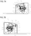
- FIG. 7A is a cross-sectional view of the drive side of the image forming apparatus A for illustrating the positioning of the cartridge B.
- FIG. 7B is a cross-sectional view of the non-drive side of the image forming apparatus A for illustrating the positioning of the cartridge B.
- a first drive-side plate 15 includes an upper guide rail 15g and a guide rail 15h as guides, and a non-drive-side plate 16 includes an upper guide rail 16d and a guide rail 16e.
- the drum bearing 73 provided on the drive side of the cartridge B has a rotation stop target portion 73c.
- the cartridge B is attached in a direction (arrow C) substantially perpendicular to the axis of the drum 62 ( FIG. 3 ).
- the cleaning frame 71 includes, on the non-drive side in the longitudinal direction, a positioning target portion 71d as a first positioning portion and a rotation stop target portion 71f as a second positioning portion.
- the guide rail 15h of the apparatus main body A guides the rotation stop target portion 73c of the cartridge B on the drive side of the cartridge B.
- the guide rails 16d and 16e of the apparatus main body A guide the positioning target portion 71d and the rotation stop target portion 71f of the cartridge B. The cartridge B is thus attached to the apparatus main body A.
- FIG. 14 is an enlarged view for illustrating the configuration of the conductive portion 1701 in detail.
- the conductive portion 1701 includes a connection section 1701e for connecting the contact section 1701a and the conductive support section 1701b.
- the conductive portion 1701 and the non-conductive portion 1702 are formed by two-color molding, and the conductive portion 1701 has a section that is formed by the resin that has spread on one side of the non-conductive portion 1702 in the longitudinal direction and a section that is formed by the resin that has spread on the other side in the molding.
- the cleaning unit 60 has a cleaning frame 71, which serves as a first frame.
- the charging roller 66 which serves as a process unit, is provided inside the cleaning frame 71.
- an electrode plate 82 which electrically connects the charging roller 66 to the apparatus main body, is attached to the side surface of the cleaning frame 71 on the non-drive side.
- the cleaning frame 71 is made of a material having a density of about 0.95 to 1.10 g/cm 3 and a flame retardancy of HB according to the UL94 standard.
- the cleaning frame 71 supports the charging roller 66 as a rotational rotating member through the charging roller bearing 67.
- the replenishing operation of the toner cartridges 2550 is performed when the toner level detection unit (not shown) installed in the apparatus main body of the image forming apparatus 2600 detects a shortage of toner remaining in the process cartridges 2500.
- the toner cartridges 2550 can be attached to and detached from the image for apparatus 2600 through an attachment unit such as an attachment guide (not shown) and a positioning member (not shown) provided in the image forming apparatus 2600.
- the process cartridges 2500 will be described in detail below.
- First to fourth toner transport devices 2602 are arranged under the toner cartridges 2550 corresponding to the respective toner cartridges 2550. Each toner transport device 2602 transports the toner received from the toner cartridge 2550 upward to supply the toner to the corresponding developing unit 2502.
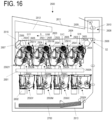
- An intermediate transfer unit 2604 which serves as an intermediate transfer member, is provided above the process cartridges 2500. The intermediate transfer unit 2604 is arranged substantially horizontally with its primary transfer portion S1 on the lower side.
- An intermediate transfer belt 2603 which is a rotational endless belt, faces the photosensitive drums 2503 and is stretched over a plurality of tension rollers.
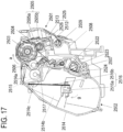
- FIG. 17 is a schematic cross-sectional view of a process cartridge according to the present embodiment.
- a photosensitive drum 2503 is driven to rotate at a predetermined speed in the direction of arrow a in FIG. 17 .
- the intermediate transfer belt 2603 is driven to rotate in the direction of arrow b in FIG. 16 (in the forward direction of the rotation of the photosensitive drum 2503).
- the charging roller 2504 uniformly charges the surface of the photosensitive drum 2503. Then, a laser beam is emitted from the scanner unit 2601 to the surface of the photosensitive drum 2503 for scanning exposure, thereby forming an electrostatic latent image on the photosensitive drum 2503 according to image information.
- the electrostatic latent image formed on the photosensitive drum 2503 is developed as a toner image (developer image) by the developing unit 2502.
- the developing unit 2502 is pressurized by the development pressure unit (not shown) provided in the main body of the image forming apparatus 2600.
- the toner image formed on the photosensitive drum 2503 is transferred, as primary transfer, onto the intermediate transfer belt 2603 by the primary transfer roller 2605.
- the recording material 2700 to which the toner image is transferred is transported to the fixing unit 2608.
- the fixing unit 2608 applies heat and pressure to the recording material 2700 thereby fixing the toner image on the recording material 2700.
- the recording material 2700 is transported to the discharge tray 2611 to complete the image forming operation.
- the cleaning blades 2505 remove the primary-transfer residual toner (waste toner) remaining on the photosensitive drums 2503 after the primary transfer step.
- the intermediate transfer belt cleaning unit 2607 removes the secondary-transfer residual toner (waste toner) remaining on the intermediate transfer belt 2603 after the secondary transfer step.
- the waste toner removed by the cleaning blades 2505 and the intermediate transfer belt cleaning unit 2607 is transported by a waste toner transport unit 2616 provided in the apparatus main body and stored in the waste toner collection container 2612.
- the image forming apparatus 2600 can also form a monochromatic or multicolor image by using only one or some (but not all) desired image forming portions.
- FIG. 17 is a schematic cross-sectional view of a process cartridge 2500 according to the present embodiment.
- FIG. 18A is a perspective view of the process cartridge 2500 as viewed from the bottom surface side.
- FIG. 18B is a perspective view of the process cartridge 2500 as viewed from the top surface side.
- the process cartridge 2500 includes a cleaning unit 2501 and a developing unit 2502.
- the cleaning unit 2501 and the developing unit 2502 are connected so as to be pivotal about a rotation support pin 2507.
- the cleaning unit 2501 includes a cleaning frame 2508, which supports various members in the cleaning unit 2501.
- the cleaning unit 2501 includes a waste toner screw 2509 extending parallel to the rotation axis of the photosensitive drum 2503.
- the cleaning frame 2508 includes cleaning bearings 2511, which rotationally support the photosensitive drum 2503 at opposite longitudinal ends of the cleaning unit 2501.
- the cleaning bearings 2511 include cleaning gear trains for transmitting drive from the photosensitive drum 2503 to the waste toner screw 2509.
- the charging roller 2504 is urged toward the photosensitive drum 2503 in the direction of arrow c by charging roller pressure springs 2512 arranged at both ends.
- the charging roller 2504 is provided so as to be driven by the photosensitive drum 2503.
- the charging roller 2504 is rotated in the direction of arrow d (forward direction of the rotation of the photosensitive drum 2503).
- the cleaning blade 2505 includes an elastic member 2505a for removing transfer residual toner (waste toner) remaining on the surface of the photosensitive drum 2503 after primary transfer, and a support member 2505b for supporting the elastic member 2505a.
- the waste toner removed from the surface of the photosensitive drum 2503 by the cleaning blade 2505 is stored in a waste toner storage chamber 2513 defined by the cleaning blade 2505 and the cleaning frame 2508.
- the waste toner screw 2509 in the waste toner storage chamber 2513 transports the waste toner stored in the waste toner storage chamber 2513 rearward of the image forming apparatus 2600 (downstream side in the attachment/detachment direction of the process cartridge 2500).
- the transported waste toner is discharged through a waste toner discharge portion 2618 and delivered to the waste toner transport unit 2616 of the image forming apparatus 2600.
- the developing unit 2502 has a development frame 2614, which supports various members of the developing unit 2502.
- the development frame 2614 is partitioned into a developing chamber 2514a, which accommodates a developing roller 2506 and a supply roller 2515, and a toner storage chamber 2514b, which stores toner and accommodates an agitation member 2516.
- the developing chamber 2514a accommodates the developing roller 2506, the supply roller 2515, and a development blade 2517.
- the developing roller 2506 carries toner as a developer carrying member, rotates in the direction of arrow e during image formation, and transports the toner to the photosensitive drum 2503 by coming into contact with the photosensitive drum 2503.
- the developing roller 2506 is rotationally supported by the development frame 2514 through development bearing units 2518 at its opposite ends in the longitudinal direction (rotation axis direction).
- the supply roller 2515 which serves as a developer supply member, is rotationally supported by the development frame 2514 through the development bearing units 2518 so as to be rotatable in contact with the developing roller 2506.
- the supply roller 2515 rotates in the direction of arrow f during image formation.
- the development blade 2517 which serves as a layer thickness controlling member that controls the thickness of the toner layer formed on the developing roller 2506, is arranged in contact with the surface of the developing roller 2506.
- the toner storage chamber 2514b accommodates the agitation member 2516, which agitates the stored toner T and transports the toner to the supply roller 2515 through a developing chamber communication port 2514c.
- the agitation member 2516 includes a rotation shaft 2516a, which is parallel to the rotation axis of the developing roller 2506, and an agitation sheet 2516b, which is flexible and serves as a transport member.
- One edge of the agitation sheet 2516b is fixed to the rotation shaft 2516a, and the other edge of the agitation sheet 2516b is a free edge.
- the agitation sheet 2516b rotates in the direction of arrow g when the rotation shaft 2516a rotates, so that the toner is agitated by the agitation sheet 2516b.
- the developing unit 2502 has the developing chamber communication port 2514c, which provides communication between the developing chamber 2514a and the toner storage chamber 2514b.
- the developing chamber 2514a is located above the toner storage chamber 2514b.
- the toner in the toner storage chamber 2514b that is lifted by the agitation member 2516 is supplied to the developing chamber 2514a through the developing chamber communication port 2514c.
- the developing unit 2502 also has a receiving port 2519 at one end on the downstream side in the attachment/detachment direction.
- a receiving port seal member 2520 and a toner receiving port shutter 2521 which is movable in the front-rear direction, are arranged above the toner receiving port 2519.
- the toner receiving port shutter 2521 closes the toner receiving port 2519.
- the toner receiving port shutter 2521 is configured to be urged and opened by the image forming apparatus 2600 in time with the attachment/detachment operation of the process cartridge 2500.
- a receiving transport passage 2522 is provided in communication with the toner receiving port 2519, and a receiving transport screw 2523 is arranged in the receiving transport passage 2522.
- the protruding section 2529a which is made of a highly flame-retardant material, functions as a fire-spreading prevention wall. This prevents the fire from spreading to the inside of the process cartridge 2500 including the cleaning frame 2508.
- the drum unit 2808 and the developing unit 2809 are coupled to each other.
- a detailed description of the process cartridge 2800 will be given below.
- the first process cartridge 2800Y contains yellow (Y) toner in the development frame 2825 and forms a yellow toner image on the surface of the photosensitive drum 2804.
- the second process cartridge 2800M contains magenta (M) toner in the development frame 2825 and forms a magenta toner image on the surface of the photosensitive drum 2804.
- the third process cartridge 2800C contains cyan (C) toner in the development frame 2825 and forms a cyan toner image on the surface of the photosensitive drum 2804.
- the fourth process cartridge 2800K contains black (K) toner in the development frame 2825 and forms a black toner image on the surface of the photosensitive drum 2804.
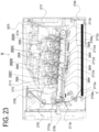
- a laser scanner unit 2714 which serves as an exposure unit, is provided above the first to fourth process cartridges 2800 (2800Y, 2800M, 2800C, and 2800K).
- the laser scanner unit 2714 outputs a laser beam L according to image information.
- the laser beam L passes through an exposure window 2810 of the process cartridge 2800 and performs scanning exposure on the surface of the photosensitive drum 2804.
- An intermediate transfer unit 2712 as a transfer member is provided under the first to fourth process cartridges 2800 (2800Y, 2800M, 2800C, and 2800K).
- the intermediate transfer unit 2712 includes a drive roller 2712e, a turn roller 2712c, and a tension roller 2712b, and a flexible transfer belt 2712a, which runs around these rollers.
- a secondary transfer roller 2706 is in contact with the drive roller 2712e through the transfer belt 2712a.
- the contact section between the transfer belt 2712a and the secondary transfer roller 2706 serves as the secondary transfer portion.
- a feeding unit 2704 is provided under the intermediate transfer unit 2712.
- the feeding unit 2704 includes a paper feed tray 2704a, which houses recording media S, and a paper feed roller 2704b.
- a fixing apparatus 2707 and a paper ejection device 2708 are provided in the upper left section of the image forming apparatus main body 2870 as viewed in FIG. 23 .
- the upper surface of the image forming apparatus main body 2870 functions as a paper ejection tray 2713.
- a fixing means of the fixing apparatus 2707 fixes the toner image on the recording medium S, which is then ejected onto the paper ejection tray 2713.
- the operation for forming a full-color image is as follows.
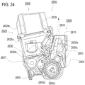
- the photosensitive drum 2804 of each of the first to fourth process cartridges 2800 (2800Y, 2800M, 2800C, and 2800K) is driven to rotate at a predetermined speed (in the direction of arrow A in FIG. 24 ).
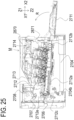
- FIG. 25 is a cross-sectional view of the image forming apparatus M in a state in which the front door 2711 is open and the tray 2871 is located inside the image forming apparatus main body 2870.
- FIG. 26 is a cross-sectional view of the image forming apparatus M in a state in which the front door 2711 is open, the tray 2871 is located outside the image forming apparatus main body 2870, and the process cartridges 2800 are housed inside the tray.
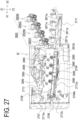
- FIG. 27 is a cross-sectional view of the image forming apparatus M in a state in which the front door 2711 is open, the tray 2871 is located outside the image forming apparatus main body 2870, and the process cartridges 2800 are removed from the tray 2871.
- the tray 2871 is movable relative to the image forming apparatus main body 2870 in the direction of arrow X1 (pushing direction) and the direction of arrow X2 direction (pulling direction), which are substantially horizontal. That is, the tray 2871 is provided such that it can be pulled out of and pushed into the image forming apparatus main body 2870.
- the tray 2871 is movable substantially in horizontal directions.
- a state in which the tray 2871 is located outside the image forming apparatus main body 2870 (the state shown in FIG. 26 ) is referred to as an outside position.
- a state in which the front door 2711 is open, the tray 2871 is located inside the image forming apparatus main body 2870, and the photosensitive drums 2804 are separated from the transfer belt 2712a (state in FIG. 25 ) is referred to as an inside position.
- the tray 2871 includes attachment portions 2871a to which the process cartridges 2800 are removably attached in the outside position.
- the process cartridges 2800 placed in the attachment portions 2871a move into the image forming apparatus main body 2870.
- a gap is maintained between the transfer belt 2712a and each photosensitive drum 2804.
- closing the front door 2711 causes a link mechanism (not shown) to lift the intermediate transfer unit 2712 in the direction of arrow Z1 to the position for image formation (the position at which the intermediate transfer belt 2712a is in contact with the photosensitive drums 2804).
- the tray 2871 can move the process cartridges 2800 into the image forming apparatus main body 2870 without the photosensitive drums 2804 coming into contact with the transfer belt 2712a.
- the tray 2871 allows the plurality of process cartridges 2800 to be moved together to a position in the image forming apparatus main body 2870 at which image formation is possible, and also allows them to be pulled out of the image forming apparatus main body 2870 together.
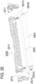
- FIG. 28 is an exploded perspective view of a drum unit 2808.
- FIG. 29 is an exploded perspective view of a developing unit 2809.
- FIG. 30 is an exploded perspective view of a process cartridge 2800 as viewed from the drive side, which is one end side in the axial direction of the photosensitive drum 2804.
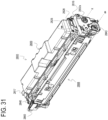
- FIG. 31 is an assembly perspective view of a process cartridge 2800 as viewed from the drive side.
- the first to fourth process cartridges 2800 (2800Y, 2800M, 2800C, and 2800K) have the same electrophotographic process mechanism but contain toner of different colors and amounts.
- Each process cartridge 2800 includes a photosensitive drum 2804 (2804Y, 2804M, 2804C, 2804K) and a process unit acting on the photosensitive drum 2804.
- the process unit includes a charging roller 2805 as a charging unit for charging the photosensitive drum 2804, a developing roller 2806 as a developing unit for developing a latent image formed on the photosensitive drum 2804, and the like.
- the process cartridge 2800 is divided into a drum unit 2808 (2808Y, 2808M, 2808C, 2808K) and a developing unit 2809 (2809Y, 2809M, 2809C, 2809K).
- longitudinal directions (Y1 and Y2 directions) of the drum unit 2808 and the developing unit 2809 are directions substantially parallel to the rotation axis ax of the photosensitive drum 2810.
- the drum unit 2808 includes a photosensitive drum 2804, a charging roller 2805, and a drum frame 2815, which is a first frame.
- the charging roller 2805 is rotationally supported by a drive-side charging roller bearing 2820a and a non-drive-side charging roller bearing 2820b, and is urged toward the photosensitive drum 2804 by pressing springs 2821a and 2821b.
- the photosensitive drum 2804 is rotationally supported by a drive-side cartridge cover member 2816 and a non-drive-side cartridge cover member 2817, which is a second frame, on opposite ends in the longitudinal direction of the process cartridge 2800.
- the non-drive-side cartridge cover member 2817 includes an electrode member 2860, which receives power from the image forming apparatus main body 2870. Details will be described below.
- a coupling member 2843 for transmitting a driving force to the photosensitive drum 2804 is provided at one longitudinal end of the photosensitive drum 2804.
- the coupling member 2843 engages with a main-body drum drive coupling 2880 (see FIG. 26 ), which serves as a drum drive output portion of the image forming apparatus main body 2870.
- the driving force of a drive motor (not shown) of the image forming apparatus main body 2870 is transmitted to the photosensitive drum 2804 through the coupling member 2843, and the photosensitive drum 2804 is rotated in the direction of arrow A ( FIG. 24 ).
- the photosensitive drum 2804 includes a drum flange 2842 at the other longitudinal end.
- the charging roller 2805 is supported by the drum frame 2815 so as to be in contact with and rotated by the photosensitive drum 2804.
- the developing unit 2809 includes a developing roller 2806, a toner transport roller 2807, a development blade 2830, a development frame 2825, and the like.
- the development frame 2825 which serves as a fourth frame (a fourth member), includes a lower frame 2825a and a lid member 2825b.
- the lower frame 2825a and the lid member 2825b have a flame retardancy of HB according to the UL94 standard.
- the lower frame 2825a is joined to the lid member 2825b by ultrasonic welding or the like.
- the development frame 2825 includes a toner storage portion 2829 for storing toner to be supplied to the developing roller 2806.
- the development frame 2825 rotationally supports the developing roller 2806 and toner transport roller 2807 through a drive-side bearing 2826 and a non-drive-side bearing 2827, and holds the development blade 2830, which controls the layer thickness of the toner on the circumference of the developing roller 2806.
- the development blade 2830 is formed by welding or otherwise joining an elastic member 2830b, which is a metal sheet having a thickness of about 0.1 mm, to a support member 2830a, which is a metal material having an L-shaped cross section.
- the development blade 2830 is fixed to the development frame 2825 with fixing screws 2830c at two locations on opposite longitudinal ends.
- the developing roller 2806 includes a metal core bar 2806c and a rubber portion 2806d.
- the developing roller 2806 is rotationally supported by the drive-side bearing 2826 and the non-drive-side bearing 2827, which are attached to opposite longitudinal ends of the development frame 2825.
- a development drive input gear 2832 for transmitting a driving force to the developing unit 2809 is provided at one longitudinal end of the developing unit 2809.
- the development drive input gear 2832 includes a development input coupling portion 2832a, which is driven by a main-body development drive coupling 2885 (see FIG. 26 ) of the image forming apparatus main body 2870.
- the driving force of the drive motor (not shown) of the image forming apparatus main body 2870 is input to the developing unit 2809 through the development input coupling portion 2832a, the development drive input gear 2832, and the like.
- the driving force input to the developing unit 2809 is transmitted to the developing roller gear 2831 so that the developing roller 2806 is rotated in the direction of arrow D in FIG. 24 .
- a development cover member 2828 which supports and covers the development drive input gear 2832, is provided at one longitudinal end of the developing unit 2809.
- the developing roller 2806 has a smaller outer diameter than the photosensitive drum 2804.
- the outer diameter of the photosensitive drum 2804 is in the range of ⁇ 18 to ⁇ 22, and the outer diameter of the developing roller 2806 is in the range of ⁇ 8 to ⁇ 14.
- the drum unit 2808 and the developing unit 2809 are coupled through the drive-side cartridge cover member 2816 and the non-drive-side cartridge cover member 2817 provided at opposite ends of the process cartridge 2800 in the longitudinal direction.
- the developing unit 2809 is supported by the drive-side cartridge cover member 2816 and non-drive-side cartridge cover member 2817 to be rotational relative to the drum unit 2808 (photosensitive drum 2804).
- the developing roller 2806 is thus positioned at a location at which the developing roller 2806 acts on the photosensitive drum 2804 during image formation.
- FIG. 31 shows a state in which the drum unit 2808 and the developing unit 2809 are coupled together through the above steps and integrally formed as the process cartridge 2800.
- the axis connecting the center of the developing unit support hole 2816a of the drive-side cartridge cover member 2816 and the center of the developing unit support hole 2817a of the non-drive-side cartridge cover member 2817 is referred to as a pivot axis K.
- the cylindrical section 2828b of the development cover member 2828 at one end is coaxial with a development input coupling 2774. That is, the developing unit 2809 is configured to receive a driving force from the image forming apparatus main body 2870 transmitted along the pivot axis K. Also, the developing unit 2809 is supported so as to be rotational about the pivot axis K.
- FIG. 32A is a perspective view of the area around the section of the drum unit 2808 that is coupled to the non-drive-side cartridge cover member 2817.
- FIG. 32A only the electrode member 2860 is shown in an exploded view.
- FIG. 32B is a cross-sectional view of the electrode member 2860.
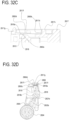
- FIG. 32C is a cross-sectional view taken along line F-F in FIG. 32A , showing a state in which the electrode member 2860 is fixed in FIG. 32A .
- FIG. 32D is a cross-sectional view taken along line J-J in FIG. 32A , showing a state in which the electrode member 2860 is fixed in FIG. 32A .
- the side of the electrode member 2860 including the contact section 2860c is bent about 3° in the direction of the conductive resin 2818 relative to a setting surface 2860e that is set on the non-drive-side cartridge cover member 2817. This is to prevent the contact section 2860c of the electrode member 2860 from being separated from the surface 2818a of the conductive resin 2818 when the electrode member 2860 is coupled to the non-drive-side cartridge cover member 2817.
- the voltage supplied from the contact spring 2893 to the electrode member 2860 is fed to the charging roller 2805 via the conductive resin 2818, which is formed in the drum frame 2815 by two-color molding, the pressing spring 2821b, and the non-drive-side charging roller bearing 2820b.
- FIG. 33A is a perspective view of a process cartridge in a state in which a storage element communication unit 2890 and a contact spring holding member 2892 are lowered.
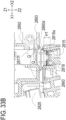
- FIG. 33B is an enlarged cross-sectional view of the power supply portion taken along line V-V in FIG. 33A .
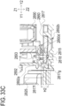
- FIG. 33C is an enlarged cross-sectional view of the power supply portion taken along line N-N in FIG. 33A .
- the image forming apparatus main body 2870 includes the contact spring holding member 2892 and holds the contact spring 2893 for supplying power to the process cartridge 2800.
- the contact spring holding member 2892 is fixed to the storage element communication unit 2890, which communicates with a storage element (not shown) provided in the process cartridge 2800.
- protruding sections 2817f protrude from the non-drive-side cartridge cover member 2817 in the direction of arrow Z1 on opposite sides of the electrode member 2860 (in directions of arrows X1 and X2).
- the height H1 of the protruding sections 2817f is set to be higher than the contact surface 2860d between the contact spring 2893 and the electrode member 2860 in the Z1 direction.
- the protruding sections 2817f are preferably located in the vicinity of the contact spring 2893 and the electrode member 2860.
- a protruding section 2817g is arranged that is integrally connected to the ends in the Y1 direction of the protruding sections 2817f of the non-drive-side cartridge cover member 2817.
- the height H2 of the protruding sections 2817g is set to be higher in the Z1 direction than the contact surface 2860d between the contact spring 2893 and the electrode member 2860.
- the protruding section 2817g is preferably located in the vicinity of the contact spring 2893 and the electrode member 2860.
- protruding sections 2892a and 2892b also extend in the longitudinal direction from the contact spring holding member 2892.
- the protruding sections 2892a and 2892b are set so as to obstruct the fire-spreading range R.
- the fire spreads over the fire-spreading ranges Q' and R'.
- the lack of components that limit the spreading of fire may spread the fire to the development frame 2825, which is made of an HB material with low flame retardancy.
- the present embodiment has the protruding sections 2817f and 2817g of the non-drive-side cartridge cover member 2817 and the protruding sections 2892a and 2892b of the contact spring holding member 2892, which have a flame retardancy of V-1, in the fire-spreading range, the fire does not spread to a component with low flame retardancy.
- the protruding sections 2817f and 2817g of the non-drive-side cartridge cover member 2817 are provided around the electrode member 2860, and the contact spring holding member 2892 having the protruding sections 2892a and 2892b is arranged above the fire-spreading range.
- the non-drive-side cartridge cover member 2817 and the contact spring holding member 2892 are made of a material with a flame retardancy of V-1 according to the UL94 standard. As a result, even if ignition occurs due to tracking, the fire does not spread to parts with low flame retardancy. It is thus possible to provide a process cartridge and an image forming apparatus that ensure safety.
- the protruding sections of the non-drive-side cartridge cover member 2817 surround the electrode member 2860, but the configuration is not limited to this.
- a protruding section may protrude from the contact spring holding member 2892 in the Z2 direction and surround the electrode member 2860.
- the non-drive-side cartridge cover member 2817 and the contact spring holding member 2892 have a flame retardancy of V-1 according to the UL94 standard, but these members may have a flame retardancy of V-1 or higher.
- the process cartridge configuration and the drum cartridge configuration of the first to third embodiments can achieve the same effects of weight reduction and fire spreading prevention in a configuration in which these configurations are bound to the apparatus main body of the image forming apparatus in a nonremovable manner.
- the process cartridge configuration and the drum cartridge configuration of the first to third embodiments are applicable to a configuration in which these configurations are bound to the image forming apparatus in a nonremovable manner.
- the use of an HB material that is a low-density resin material reduces the overall weight of the image forming apparatus, achieving both the safety and weight reduction of the image forming apparatus. As a result, the impact value of the image forming apparatus main body during physical distribution can be lowered. This allows the packaging of the image forming apparatus to be smaller, improving the distribution efficiency.
- a cartridge for an image forming apparatus includes: a process unit to be used to form an image; a first member including a first resin material; a second member including a second resin material having higher flame retardant capability than the first resin material; and an electrode member including a contact section configured to be supplied with power from an apparatus main body of the image forming apparatus.
- the electrode member is configured to electrically connect the apparatus main body to the process unit.
- the second resin material of the second member has a greater density than the first resin material of the first member.
- the contact section is located in the vicinity of the first and second members and is closer to the second member than to the first member.
- This application is a divisional application of European patent application no. 21 193 735.4 (the "parent application"), also published under no. EP 3 961 310 A1 .
- the original claims of the parent application are repeated below in the present specification in the form of items and form part of the content of this divisional application as filed.
Landscapes
- Physics & Mathematics (AREA)
- General Physics & Mathematics (AREA)
- Engineering & Computer Science (AREA)
- Computer Vision & Pattern Recognition (AREA)
- Electrophotography Configuration And Component (AREA)
Abstract
Description
- The present invention relates to a cartridge and an image forming apparatus that uses the cartridge.
- In an electrophotographic image forming apparatus that uses a process cartridge system, when a cartridge is attached to the apparatus main body, an electrode member of the cartridge is in contact with a main body electrode of the apparatus main body, thereby electrically connecting a conduction-target member, such as a process unit, of the cartridge to the apparatus main body. As an example of the electrode member,
Japanese Patent Application Publication No. 2012-63750 - However, in the above-mentioned conventional example, since the conductive portion, which may be conductive resin or metal plate, for example, is attached to the frame, the frame needs to be made of a resin with high flame retardant function (flame-retardant material) in order to ensure electrical safety in the vicinity of the conductive portion. The use of flame-retardant material limits the choice of materials. This poses challenges particularly to the weight reduction of the frame components.
- The present invention provides a technique that achieves both the weight reduction and safety of a frame for supporting a process unit.
- The present invention in its one aspect provides a cartridge for an image forming apparatus as specified in
claims 1 to 18,20. - The present invention in its one aspect provides an image forming apparatus as specified in
claims 19. - According to the present invention, it is possible to achieve both the weight reduction and safety of a frame that supports a process unit.
- Further features of the present invention will become apparent from the following description of exemplary embodiments with reference to the attached drawings.
-
-
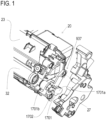
FIG. 1 is an exploded view of a development contact configuration according to a first embodiment; -
FIG. 2 is a cross-sectional view of an image forming apparatus main body and a cartridge of the first embodiment; -
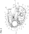
FIG. 3 is a cross-sectional view of a cartridge of the first embodiment; -
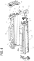
FIG. 4 is a perspective view illustrating the configuration of a cartridge of the first embodiment; -
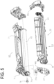
FIG. 5 is a perspective view illustrating the configuration of a cleaning unit of the first embodiment; -
FIGS. 6A and 6B are cross-sectional views for illustrating the attachment of the cartridge of the first embodiment; -
FIGS. 7A and 7B are cross-sectional views for illustrating the positioning of the cartridge of the first embodiment; -
FIGS. 8A to 8D are perspective views for illustrating the attachment and detachment of the cartridge of the first embodiment; -
FIG. 9 is a perspective view illustrating the configuration of the cartridge of the first embodiment; -
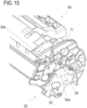
FIG. 10 is an exploded perspective view illustrating the charging contact configuration of the cartridge of the first embodiment; -
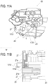
FIGS. 11A and 11B are diagrams illustrating the development contact configuration of the cartridge of the first embodiment; -
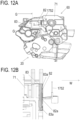
FIGS. 12A and 12B are diagrams illustrating the charging contact configuration of the cartridge of the first embodiment; -
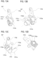
FIGS. 13A to 13D are diagrams illustrating a conductive bearing member of the first embodiment; -
FIG. 14 is an enlarged view illustrating a conductive portion of the first embodiment; -
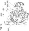
FIG. 15 is an exploded perspective view of a developing unit of a second embodiment; -
FIG. 16 is a schematic view of an image forming apparatus of the second embodiment; -
FIG. 17 is a cross-sectional view of a cartridge of the second embodiment; -
FIGS. 18A and 18B are perspective views of a cartridge of the second embodiment; -
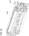
FIG. 19 is a perspective view of a developing unit of the second embodiment; -
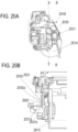
FIG. 20A is a side view of the developing unit of the second embodiment; -
FIG. 20B is an enlarged cross-sectional view of the developing unit of the second embodiment; -
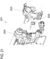
FIG. 21 is an exploded perspective view of a cleaning unit of the second embodiment; -
FIG. 22A is a side view of the cleaning unit of the second embodiment; -
FIG. 22B is an enlarged cross-sectional view of the cleaning unit of the second embodiment; -
FIG. 23 is a schematic cross-sectional view of an image forming apparatus of a third embodiment; -
FIG. 24 is a cross-sectional view of a cartridge of the third embodiment; -
FIG. 25 is a cross-sectional view of the image forming apparatus of the third embodiment; -
FIG. 26 is a cross-sectional view of the image forming apparatus of the third embodiment; -
FIG. 27 is a cross-sectional view of the image forming apparatus of the third embodiment; -
FIG. 28 is an exploded perspective view of a drum unit of the third embodiment; -
FIG. 29 is an exploded perspective view of a developing unit of the third embodiment; -
FIG. 30 is an exploded perspective view of a cartridge of the third embodiment; -
FIG. 31 is a assembly perspective view of a cartridge of the third embodiment; -
FIG. 32A is a perspective view of a cartridge and a non-drive-side cartridge cover member of the third embodiment; -
FIG. 32B is a cross-sectional view of the non-drive-side cartridge cover member of the third embodiment; -
FIG. 32C is a cross-sectional view of the cartridge and the non-drive-side cartridge cover member of the third embodiment; -
FIG. 32D is a cross-sectional view of the cartridge and the non-drive-side cartridge cover member of the third embodiment; -
FIG. 33A is a perspective view illustrating a storage element communication unit and a contact spring holding member of the third embodiment; -
FIG. 33B is an enlarged view illustrating the storage element communication unit and the contact spring holding member of the third embodiment; -
FIG. 33C is an enlarged view illustrating the storage element communication unit and the contact spring holding member of the third embodiment. -
FIG. 34A is a perspective view showing a cleaning frame body portion independently extracted as a key component of the charging contact configuration of a variation of theembodiment 1. -
FIG. 34B is a perspective view showing key components of the charging contact configuration extracted in a state in which a contact cover portion is formed in the cleaning frame body portion by two-color molding of the variation of theembodiment 1. -
FIG. 35 is an exploded perspective view showing the key components of the charging contact configuration extracted of the variation of theembodiment 1. -
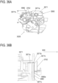
FIG. 36A is a side view for illustrating the charging contact configuration of the variation of theembodiment 1. -
FIG. 36B is an enlarged cross-sectional view of the charging contact taken along line H-H inFIG. 36A . - Hereinafter, a description will be given, with reference to the drawings, of embodiments (examples) of the present invention. However, the sizes, materials, shapes, their relative arrangements, or the like of constituents described in the embodiments may be appropriately changed according to the configurations, various conditions, or the like of apparatuses to which the invention is applied. Therefore, the sizes, materials, shapes, their relative arrangements, or the like of the constituents described in the embodiments do not intend to limit the scope of the invention to the following embodiments.
- Referring to drawings, an embodiment of the present invention is now described in detail. A direction along the rotation axis of an electrophotographic photosensitive drum is referred to as a longitudinal direction. In the longitudinal direction, the side on which the electrophotographic photosensitive drum receives a driving force from the image forming apparatus main body is referred to as a drive side, and the opposite side is referred to as a non-drive side. Referring to
FIGS. 2 and3 , the overall configuration and an image formation process are now described.FIG. 2 is a cross-sectional view of an apparatus main body (electrophotographic image forming apparatus main body, image forming apparatus main body) A and a process cartridge B of an electrophotographic image forming apparatus of one embodiment according to the present invention.FIG. 3 is a cross-sectional view of the process cartridge B. The process cartridge is formed by integrating a photosensitive member and a process unit which acts on the photosensitive member, into a cartridge. The process cartridge is attached to the electrophotographic image forming apparatus main body in a detachable manner. For example, the process cartridge may be formed by integrating a photosensitive member and at least one of a developing unit, a charging unit, and a cleaning unit as a process unit into a cartridge. The electrophotographic image forming apparatus forms an image on a recording medium using an electrophotographic image forming method. Examples of the electrophotographic image forming apparatus include an electrophotographic copier, an electrophotographic printer (e.g., an LED printer and laser beam printer), a facsimile machine, and a word processor. The apparatus main body A is the portion of the electrophotographic image forming apparatus excluding the process cartridge B (hereinafter, referred to as cartridge B). - The electrophotographic image forming apparatus (image forming apparatus) shown in
FIG. 2 is a laser beam printer using an electrophotographic technique in which the cartridge B is attached to the apparatus main body A in a detachable manner. When the cartridge B is attached to the apparatus main body A, an exposure apparatus 3 (laser scanner unit) is arranged that forms latent images on an electrophotographicphotosensitive drum 62, which serves as an image bearing member of the cartridge B. Asheet tray 4, which is arranged under the cartridge B, stores recording media (hereinafter referred to as sheet material PA) on which images are formed. The electrophotographicphotosensitive drum 62 is a photosensitive member (electrophotographic photosensitive member) used to form electrophotographic images. The apparatus main body A further includes a pickup roller 5a, a pair of feedingrollers 5b, atransfer guide 6, atransfer roller 7, a transport guide 8, a fixingapparatus 9, a pair ofdischarge rollers 10, and adischarge tray 11, which are arranged along the transport direction D of the sheet material PA. The fixingapparatus 9 includes a heating roller 9a and apressing roller 9b. - The outline of the image formation process is now described. In response to a print start signal, the electrophotographic photosensitive drum (hereinafter, referred to as
photosensitive drum 62 or simply as drum 62) is driven to rotate in the direction of arrow R at a predetermined circumferential speed (process speed). A charging roller (charging member) 66, to which a bias voltage is applied, is in contact with the outer circumferential surface of thedrum 62 and uniformly charges the outer circumferential surface of the drum 62 (seeFIG. 3 ). Theexposure apparatus 3 outputs a laser beam L according to image information. The laser beam L passes through alaser opening 71h (seeFIG. 2 ) provided in acleaning frame 71 of the cartridge B, and scans the outer circumferential surface of thedrum 62 to perform exposure. An electrostatic latent image corresponding to the image information is thus formed on the outer circumferential surface of thedrum 62. - As shown in
FIG. 3 , a developingunit 20, which serves as the developing apparatus, includes atoner chamber 29 storing toner T. A transport member (agitation member) 43 rotates to agitate and transport the toner T to atoner supply chamber 28. The magnetic force of a magnet roller 34 (stationary magnet) holds the toner T on the surface of a developingroller 32. The developingroller 32 is a developer carrying member that carries developer (toner T) on its surface to develop the latent image formed on thedrum 62. Adevelopment blade 42 friction-charges the toner T and controls the layer thickness of the toner T on the circumferential surface of the developingroller 32, which serves as the developer carrying member. - The toner T is supplied to the
drum 62 according to the electrostatic latent image and develops the latent image. As a result, the latent image is formed as a visible toner image. Thedrum 62 is an image bearing member that bears a latent image or an image to be formed with toner (toner image, developer image) on its surface. As shown inFIG. 2 , the sheet material PA stored in a lower part of the apparatus main body A is sent out from thesheet tray 4 by the pickup roller 5a and the pair of feedingrollers 5b in time with the output of a laser beam L. The sheet material PA is transported along thetransfer guide 6 to the transfer position between thedrum 62 and thetransfer roller 7. At this transfer position, the toner image is sequentially transferred from thedrum 62 to the sheet material PA. - The sheet material PA to which the toner image is transferred is transported away from the
drum 62 and to the fixingapparatus 9 along the transport guide 8. The sheet material PA then passes through the nip portion of the heating roller 9a and thepressing roller 9b of the fixingapparatus 9. The fixing process of pressing and heating at the nip portion fixes the toner image on the sheet material PA. The sheet material PA that has undergone the toner image fixing process is transported to the pair ofdischarge rollers 10 and discharged to thedischarge tray 11. - As shown in
FIG. 3 , the residual toner on the outer circumferential surface of thedrum 62 after transferring is removed by a cleaningmember 77 and used for an image formation process again. The toner removed from thedrum 62 is stored in awaste toner chamber 71b of atoner cleaning unit 60. Thecleaning unit 60 is a photosensitive drum unit including thephotosensitive drum 62. In the foregoing description, the chargingroller 66, the developingroller 32, thetransfer roller 7, and the cleaningmember 77 function as a process unit for acting on thedrum 62. - Referring to
FIGS. 3 ,4 , and5 , the overall configuration of the cartridge B is now described.FIG. 3 is a cross-sectional view of the cartridge B, andFIGS. 4 and5 are perspective views illustrating the configuration of the cartridge B. In this embodiment, the description of the screws for connecting parts is omitted. The cartridge B includes the cleaning unit (photosensitive member holding unit, drum holding unit, image bearing member holding unit, first unit) 60 and the developing unit (developer carrying member holding unit, second unit) 20. - As shown in
FIG. 3 , thecleaning unit 60 includes thedrum 62, the chargingroller 66, the cleaningmember 77, and acleaning frame 71, which supports these components. On the drive side, thedrum 62 includes a drive-side drum flange 63, which is rotationally supported by a hole section 73a of a drum bearing 73 (seeFIG. 4 ). In a broad sense, the drum bearing 73 and thecleaning frame 71 can be collectively referred to as a cleaning frame. As shown inFIG. 5 , on the non-drive side, adrum shaft 78 is press-fitted into ahole section 71c formed in thecleaning frame 71 so that a hole section (not shown) of the non-drive-side drum flange is rotationally supported. - The drum flanges are portions that are rotationally borne and supported by the respective bearing portions. As shown in
FIG. 3 , the chargingroller 66 and the cleaningmember 77 of thecleaning unit 60 are in contact with the outer circumferential surface of thedrum 62. The cleaningmember 77 has a rubber blade 77a, which is a blade-shaped elastic member made of rubber as an elastic material, and asupport member 77b supporting the rubber blade. The rubber blade 77a substantially extends in the direction opposite to the rotation direction of thedrum 62 and is in contact with thedrum 62. That is, the rubber blade 77a is in contact with thedrum 62 with its distal edge pointing toward the upstream side in the rotation direction R of thedrum 62. The waste toner removed from the surface of thedrum 62 by the cleaningmember 77 is stored in thewaste toner chamber 71b defined by thecleaning frame 71 and the cleaningmember 77. - As shown in
FIG. 3 , a scoopingsheet 65 for preventing waste toner from leaking from thecleaning frame 71 is provided at an edge of thecleaning frame 71 in contact with thedrum 62. The chargingroller 66 is rotationally attached to thecleaning unit 60 through chargingroller bearings 67 located at opposite ends in the longitudinal direction of thecleaning frame 71. The longitudinal direction of the cleaning frame 71 (the longitudinal direction of the cartridge B) is substantially parallel to the direction in which the rotation axis of thedrum 62 extends (axial direction). Hereinafter, the longitudinal direction and the axial direction therefore refer to the axial direction of thedrum 62 unless otherwise specified. Urgingmembers 68 press the chargingroller bearings 67 toward thedrum 62, thereby pressing the chargingroller 66 against thedrum 62. The chargingroller 66 is driven and rotated by the rotation of thedrum 62. - As shown in
FIG. 3 , the developingunit 20 includes the developingroller 32, adeveloper container 23 supporting the developingroller 32, and adevelopment blade 42. The developingroller 32 is rotationally attached to thedeveloper container 23 through bearing members 26 (FIG. 4 ) and27 (FIG. 5 ) provided at opposite ends. The developingroller 32 contains themagnet roller 34. The developingunit 20 includes thedevelopment blade 42 for controlling the toner layer on the developingroller 32. As shown inFIGS. 4 and5 , spacingmembers 38 are attached to opposite ends of the developingroller 32. Thespacing members 38 are brought into contact with thedrum 62, so that the developingroller 32 is held with a small gap created between the developingroller 32 and thedrum 62. As shown inFIG. 3 , aspout prevention sheet 33 for preventing the toner from leaking from the developingunit 20 is provided at an edge of thedeveloper container 23 and in contact with the developingroller 32. Atransport member 43 is provided in thetoner chamber 29 defined by thedeveloper container 23 and abase member 22. Thetransport member 43 agitates the toner stored in thetoner chamber 29 and transports the toner to thetoner supply chamber 28. - As shown in
FIGS. 4 and5 , the cartridge B is formed by combining thecleaning unit 60 and the developingunit 20. To join the developingunit 20 to thecleaning unit 60, the center of a first developing-side support boss 26a of the bearingmember 26 is aligned with a first suspension hole 71i on the drive side of thecleaning frame 71, and the center of a second developing-side support boss 27a of the bearingmember 27 is aligned with asecond suspension hole 71j on the non-drive side. Specifically, the developingunit 20 is moved in the direction of arrow G so that the first and second developing-side support bosses 26a and 27a are fitted into the first andsecond suspension holes 71i and 71j. The developingunit 20 is thus movably connected to thecleaning unit 60. Specifically, the developingunit 20 is rotationally (pivotally) connected to thecleaning unit 60. That is, the developingroller 32 is coupled to thedrum 62 so as to be movable toward and away from thedrum 62. Then, the drum bearing 73 is coupled to thecleaning unit 60 to form the cartridge B. - In this embodiment, a non-drive-
side urging member 46L (FIG. 5 ) and a drive-side urging member 46R (FIG. 4 ) are compression springs. The urging force of the springs allows the drive-side urging member 46R and the non-drive-side urging member 46L to urge the developingunit 20 to thecleaning unit 60, ensuring that the developingroller 32 is pressed in the direction of thedrum 62. The present embodiment also includes thespacing members 38 at opposite ends of the developingroller 32. That is, thedrum 62 is in contact with the developingroller 32 through thespacing members 38 with a predetermined contact pressure, so that the developingroller 32 is held with a predetermined gap created between the developingroller 32 and thedrum 62. The relative positions of these components are thus determined. - Referring to
FIGS. 6A, 6B ,7A, and 7B , the attachment of the cartridge B is now specifically described.FIG. 6A is a cross-sectional view of the drive-side guide portion of the image forming apparatus A for illustrating the attachment of the cartridge B.FIG. 6B is a cross-sectional view of the non-drive-side guide portion of the image forming apparatus A for illustrating the attachment of the cartridge B.FIG. 7A is a cross-sectional view of the drive side of the image forming apparatus A for illustrating the positioning of the cartridge B.FIG. 7B is a cross-sectional view of the non-drive side of the image forming apparatus A for illustrating the positioning of the cartridge B. - The cartridge B is attached as follows. As shown in
FIGS. 6A and 6B , a first drive-side plate 15 includes an upper guide rail 15g and aguide rail 15h as guides, and a non-drive-side plate 16 includes anupper guide rail 16d and aguide rail 16e. The drum bearing 73 provided on the drive side of the cartridge B has a rotationstop target portion 73c. The cartridge B is attached in a direction (arrow C) substantially perpendicular to the axis of the drum 62 (FIG. 3 ). - The
cleaning frame 71 includes, on the non-drive side in the longitudinal direction, apositioning target portion 71d as a first positioning portion and a rotationstop target portion 71f as a second positioning portion. When the cartridge B is attached through acartridge insertion slot 17 of the apparatus main body A, theguide rail 15h of the apparatus main body A guides the rotationstop target portion 73c of the cartridge B on the drive side of the cartridge B. On the non-drive side of the cartridge B, theguide rails positioning target portion 71d and the rotationstop target portion 71f of the cartridge B. The cartridge B is thus attached to the apparatus main body A. - The closing of an opening/closing
door 13 is now described. As shown inFIGS. 6A, 6B ,7A, and 7B , the first drive-side plate 15 has an upper positioning portion 15a, alower positioning portion 15b, and arotation stop portion 15c as positioning portions, and the non-drive-side plate 16 has apositioning portion 16a and an upperrotation stop portion 16c. Thedrum bearing 73 includes an upper positioning target portion (first positioning target portion, first protrusion, first bulging portion) 73d and a lower positioning target portion (second positioning target portion, second protrusion, second bulging portion) 73f. -
Cartridge pressing members door 13.Cartridge pressing springs drum bearing 73 has apressing target portion 73e as an urging force receiving portion, and thecleaning frame 71 has a pressing target portion 71o on the non-drive side (seeFIG. 3 ). When the opening/closingdoor 13 is closed, thecartridge pressing members cartridge pressing springs pressing target portions 73e and 71o of the cartridge B (seeFIGS. 7A and 7B ). - As a result, on the drive side, the upper
positioning target portion 73d, the lowerpositioning target portion 73f, and the rotationstop target portion 73c of the cartridge B are fixed to the upper positioning portion 15a, thelower positioning portion 15b, and therotation stop portion 15c, respectively, of the apparatus main body A. The cartridge B and thedrum 62 are thus positioned on the drive side. Likewise, on the non-drive side, thepositioning target portion 71d and the rotationstop target portion 71f of the cartridge B are fixed to thepositioning portion 16a and therotation stop portion 16c, respectively, of the apparatus main body A. The cartridge B and thedrum 62 are thus positioned on the non-drive side. - The above description of an example of the configuration for positioning the cartridge B relative to the apparatus main body A is not intended to limit the means for positioning. A configuration may be used that directly acts on the
positioning target portion 73d and the rotationstop target portion 73f on the drive side of the cartridge B, and thepositioning target portion 71d and the rotationstop target portion 71f on the non-drive side to fix the positioning portions. - Referring to
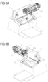
FIGS. 8A, 8B ,8C, and 8D , the configuration in which the cartridge B receives a driving force from the apparatus main body A is now described.FIG. 8A is a diagram showing the configuration of a drive portion of the apparatus main body A.FIG. 8B is a diagram showing the configuration of a drive portion of the cartridge B.FIG. 8C is a diagram showing a state before the drive portions of the apparatus main body A and the cartridge B are engaged.FIG. 8D is a diagram showing a state in which the power of the apparatus main body A is turned on and the drive portions of the apparatus main body A and the cartridge B are engaged. - As shown in
FIG. 8A , the apparatus main body A includes adrive transmission member 81, which receives a driving force from a driving source (not shown) of the apparatus main body A and transmits the driving force to the cartridge B. As shown inFIG. 8B , the cartridge B includes a drivenportion 63b in the drive-side drum flange 63 to engage with thedrive transmission member 81 and receive the driving force. When the opening/closingdoor 13 is closed and the power of the apparatus main body A is turned on, thedrive transmission member 81 moves in the direction of arrow E inFIG. 8C . Then, as shown inFIG. 8D , adrive transmission portion 81b of thedrive transmission member 81 engages with the drivenportion 63b of the drive-side drum flange 63, and thedrum 62 is rotated through the drive-side drum flange 63. The outer circumference of thedrive transmission member 81 has agear shape 81g. Additionally, a developing roller gear 90 is coupled to an end of the developingroller 32 of the cartridge B. When the drivenportion 63b of the drive-side drum flange 63 is engaged as shown inFIG. 8D , thegear shape 81g on thedrive transmission member 81 and the developing roller gear 90 are arranged so as to mesh with each other. That is, when thedrive transmission member 81 rotates thedrum 62 through the drive-side drum flange, the developingroller 62 also rotates simultaneously through the developing roller gear 90. - Referring to
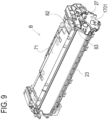
FIGS. 1 ,9 ,11A, and 11B , the development contact configuration, which is a feature of the present embodiment, of the cartridge B is now described.FIG. 1 is an exploded perspective view of the developingunit 20 showing the key components of the development contact configuration extracted.FIG. 9 is a perspective view of the cartridge B,FIG. 11A is a side view of the cartridge B for illustrating the development contact configuration, andFIG. 11B is an enlarged cross-sectional view of the area around the development contact taken along line I-I inFIG. 11A . - As shown in
FIG. 1 , the developingunit 20 includes adeveloper container 23, which serves as a first frame (a first member), and a developingroller 32, which serves as a process unit. Thedeveloper container 23 is made of a material(a first resin material) having a density of about 0.95 to 1.10 g/cm3 and a flame retardancy of HB according to the UL94 standard. It is known that adding an additive to a resin material, which generally has the property of igniting in contact with flame, can render the resin flame retardant. When an additive is added to one type of resin material, a higher flame-retardant effect results in a greater specific gravity of the resin. This causes a problem that the weight of the necessary resin material in the entire product is increased, causing a greater load on the environment. In this embodiment, thedeveloper container 23 is made of a material that is free of such an additive and has a low density. The developingroller 32 has the function of carrying developer by receiving a predetermined bias. The developingroller 32 is rotationally supported as a rotating member by thedeveloper container 23 through the bearing member 26 (seeFIG. 4 ) on the drive side and aconductive bearing member 937 and the bearingmember 27 on the non-drive side. - The flame retardant capability is now described. In the present embodiment, the UL94 standard is used to assess the flame retardant capability. To assess the flame retardant capability of a resin, such as a plastic, it is first determined whether the material is self-extinguishing. The burning tests according to the UL94 standard generally include a horizontal burning test for resin materials that are not self-extinguishing, and vertical burning tests for resin materials that are self-extinguishing. Examples of resin materials for the horizontal burning test include HB materials. Examples of resin materials for the vertical burning tests include 5VA, 5VB, V-0, V-1, and V-2 materials. As the measures for the grades according to the UL94 standard, a material that passes the horizontal burning test for HB materials needs to exhibit a slow-burning property even though it is not self-extinguishing and have a burning rate of 40 mm/min or less when the test sample has a thickness of 3 mm or more. As for the vertical burning tests, a V-0 material needs to have a burning time of 10 seconds or less when a flame is applied to the test sample twice for 10 seconds each, and V-1 and V-2 materials need to have a burning time of 30 seconds or less when a flame is applied to the test sample twice for 10 seconds each. Here, the shorter the burning time, the harder it is to burn. That is, "high flame retardant capability" in this embodiment not only indicates a difference in flame retardant grade but also indicates a shorter burning time in the same burning test.
- Other than the UL94 standard, the oxygen index according to the JIS standard may be used. The oxygen index is an index indicating the minimum oxygen concentration in percentage required for an ignited resin material to keep burning. A greater oxygen index indicates higher flame retardant capability. For example, the oxygen index is about 15 to 19 with an HB material, about 24 to 25 with a V-2 material, about 25 to 29 with a V-1 material, and about 29 or more with a V-0 material.
- As shown in
FIGS. 1 ,11A, and 11B , theconductive bearing member 937 includes aspring contact 1751, which is a power supply member of the image forming apparatus and functions to apply a predetermined bias to the developingroller 32, and aconductive portion 1701, which is an electrode member made of a conductive resin. Thespring contact 1751 and theconductive portion 1701 form an electrically conductive path between the apparatus main body and the developingroller 32. - As shown in
FIG. 1 , theconductive bearing member 937 includes theconductive portion 1701 and anon-conductive portion 1702 as a second frame (a second member), which are integrally formed. Thenon-conductive portion 1702 is made of a material (a second resin material) that has a density of about 1.12 to 1.50 g/cm3 and a flame retardancy of V-1 according to the UL94 standard, that is, has higher flame retardant capability than thedeveloper container 23. As shown inFIGS. 11A and 11B , theconductive portion 1701 includes acontact section 1701a exposed outward to be in contact with thespring contact 1751, which is a power supply member of the image forming apparatus, to receive power, and aconductive support section 1701b, which serves as a shaft support section that rotationally supports the developingroller 32. -
FIGS. 13A to 13B are diagrams for illustrating the details of theconductive bearing member 937.FIGS. 13B and 13C are exploded views in which theconductive portion 1701 and thenon-conductive portion 1702 are displaced in the longitudinal direction. AlthoughFIGS. 13B and 13C show theconductive portion 1701 and thenon-conductive portion 1702 arranged side by side in the longitudinal direction, these portions are not configured to be integrated by fitting to each other in the longitudinal direction. In this embodiment, theconductive portion 1701 and thenon-conductive portion 1702 are formed by two-color molding, and theconductive portion 1701 has a section that is shaped to spread on one side of thenon-conductive portion 1702 in the longitudinal direction and a section that is shaped to spread on the other side. For example, thecontact section 1701a and theconductive support section 1701b are sections of theconductive portion 1701 that are formed on opposite sides of thenon-conductive portion 1702 in the longitudinal direction. That is,FIGS. 13B and 13C are imaginary views that show theconductive portion 1701 and thenon-conductive portion 1702 displaced in the longitudinal direction to clarify their configurations (especially the parts of the configurations that are invisible from the outside when these portions are integrated).FIG. 13A shows a state in which theconductive portion 1701 and thenon-conductive portion 1702 are integrated. - As shown in
FIG. 13C , thenon-conductive portion 1702 has anelectrode seating surface 1702c, which is opposed to thecontact section 1701a in the longitudinal direction and extends in a direction perpendicular to the longitudinal direction. - The
contact section 1701a of theconductive portion 1701 is closer to thenon-conductive portion 1702 than to thedeveloper container 23 and in contact with thenon-conductive portion 1702. For example, if an incident such as anomalies in the high voltage power source of the apparatus main body A causes an electric discharge between thespring contact 1751, which serves as the power supply portion, and thecontact section 1701a, this may create an electric ignition source. In this respect, the present configuration has thenon-conductive portion 1702 with high flame retardant capability in contact with thecontact section 1701a. If any ignition occurring in thecontact section 1701a is about to spread the fire to thenon-conductive portion 1702, thenon-conductive portion 1702 generates nonflammable gas from the inside of its material and carbonizes the resin surface to stop the spreading of the fire to the inside of the resin, thereby facilitating self-extinguishing. As a result, even when thecontact section 1701a of theconductive portion 1701 is located near thedeveloper container 23, the spreading of fire to thedeveloper container 23 can be prevented since thecontact section 1701a is closer to thenon-conductive portion 1702 than to thedeveloper container 23. The term "vicinity" used herein refers to a range that is affected by ignition originating from an electric ignition source caused by electric discharge occurring between the power supply portion and the contact section due to anomalies or the like. - That is, in the cartridge B of this embodiment, the
developer container 23 is made of an HB material that is a low-density resin material to reduce the overall weight of the product, while a highly flame-retardant V-1 material is used in the vicinity of the connection section, which serves as an electrically conductive path, between the apparatus main body A and the cartridge B. This provides the cartridge B that achieves both the safety and weight reduction of the entire product. - Additionally, the bearing
member 27, which serves as a third frame (a third member), holds theconductive bearing member 937 and is fastened to thedeveloper container 23. This bearingmember 27 is made of a material that has a density of about 1.12 to 1.50 g/cm3 and a flame retardancy of V-1 according to the UL94 standard. Furthermore, as shown inFIG. 11B , the bearingmember 27 is adjacent to theconductive portion 1701 and has a protrudingsection 27a that protrudes beyond theelectrode seating surface 1702c (seeFIG. 13C ) of thenon-conductive portion 1702 in the longitudinal direction W. That is, the bearingmember 27 has the protrudingsection 27a formed so as to shield theelectrode seating surface 1702c of thenon-conductive portion 1702 from the outside. For example, anomalies in the high voltage power source of the apparatus main body A or other factors may cause an electric discharge between thespring contact 1751, which serves as a power supply portion, and thecontact section 1701a of theconductive portion 1701, resulting in electric ignition. At this time, even if ignition occurs in the area from thecontact section 1701a of theconductive portion 1701 to theelectrode seating surface 1702c of thenon-conductive portion 1702 in the longitudinal direction W, the protrudingsection 27a contains the nonflammable gas generated from thenon-conductive portion 1702 and the bearingmember 27. This further facilitates the self-extinguishing of thenon-conductive portion 1702, so that the spreading of fire can be stopped at theelectrode seating surface 1702c. Accordingly, the safety can be further improved. - In terms of the containment of the nonflammable gas and the suppression of fire spreading, the protruding
section 27a is preferably configured to protrude so as to completely surround the periphery (outer circumference) of theelectrode seating surface 1702c. However, the protrudingsection 27a may have any of various configurations as long as it provides a certain effect. Since fire tends to spread upward in the vertical direction, the effect of preventing fire spreading can be achieved by arranging the protrudingsection 27a so as to obstruct the space between theelectrode seating surface 1702c and thedeveloper container 23, which is the first frame, at least above theelectrode seating surface 1702c in the vertical direction. That is, the protruding section of the present invention can have the effect of suppressing the spreading of fire when ignition occurs, as long as the protruding section at least has a section extending above the contact section in the vertical direction. It should be apparent that the same applies to the configurations of the other protruding sections described below. -
FIGS. 13A to 13D are perspective views for illustrating the configuration of theconductive bearing member 937 in detail.FIG. 13A shows theconductive bearing member 937 in which theconductive portion 1701 and thenon-conductive portion 1702 are integrally molded.FIGS. 13B and 13C are imaginary views showing theconductive portion 1701 and thenon-conductive portion 1702 of theconductive bearing member 937 displaced in the longitudinal direction for illustration purpose. - As shown in
FIG. 13B , theconductive portion 1701 and thenon-conductive portion 1702 of theconductive bearing member 937 are made of different resin materials and formed integrally. Theconductive portion 1701 has aconductive support section 1701b that supports the inner circumference portion of the developingroller 32, which is a rotating member. Referring toFIG. 13D , which shows a cross section ofFIG. 13A , thenon-conductive portion 1702 has an innercircumference support section 1702a and an outercircumference support section 1702b for supporting theconductive portion 1701. The innercircumference support section 1702a and the outercircumference support section 1702b support the cylindricalconductive support section 1701b of theconductive portion 1701 so as to sandwich it from both the inner circumference side and the outer circumference side. This limits the tilting of theconductive support section 1701b relative to thenon-conductive portion 1702 even when a gap is created between theconductive portion 1701 and thenon-conductive portion 1702 due to the difference in heat expansion rate of the materials. The developingroller 32 can therefore rotate stably. -
FIG. 14 is an enlarged view for illustrating the configuration of theconductive portion 1701 in detail. Theconductive portion 1701 includes aconnection section 1701e for connecting thecontact section 1701a and theconductive support section 1701b. As described above, theconductive portion 1701 and thenon-conductive portion 1702 are formed by two-color molding, and theconductive portion 1701 has a section that is formed by the resin that has spread on one side of thenon-conductive portion 1702 in the longitudinal direction and a section that is formed by the resin that has spread on the other side in the molding. Theconnection section 1701e is the section that connects the section that is shaped to spread on one side of thenon-conductive portion 1702 in the longitudinal direction, which is thecontact section 1701a, and the section that is shaped to spread on the other side, which is theconductive support section 1701b. In the two-color molding of theconductive portion 1701, resin is injected through agate section 1701c, which serves as the injection port, into the cavity in the order of thecontact section 1701a, theconnection section 1701e, and theconductive support section 1701b. In this configuration, as viewed in a direction perpendicular to a plane including thecontact section 1701a, theconductive portion 1701 is shaped such that thegate section 1701c and theconnection section 1701e overlap (overlap and are included in) thecontact section 1701a. Furthermore, as viewed in the same direction, thecontact section 1701a and theconductive support section 1701b partially overlap each other. That is, the resin injection path from thegate section 1701c to theconductive support section 1701b is shorter than that in a configuration in which the injection path bypasses and extends outside thenon-conductive portion 1702, for example. This reduces the amount of resin material used to form theconductive portion 1701. Consequently, in case of any ignition of thecontact section 1701a, the spreading of fire along the conductive resin can be reduced, increasing the safety of the contact configuration. - In this embodiment, polystyrene (PS) is used for the
developer container 23 as the first frame. A mixed resin of polycarbonate and acrylonitrile butadiene styrene (PC-ABS) is used for thenon-conductive portion 1702 as the second frame and the bearingmember 27 as the third frame. A conductive polyacetal (POM) is used for theconductive portion 1701 as the resin electrode member. However, these materials are not limited to those of the present embodiment. - Referring to
FIGS. 10 ,12A, and 12B , the charging contact configuration, which is a feature of the present embodiment, is now described in detail.FIG. 10 is an exploded perspective view showing the key components of the charging contact configuration extracted.FIG. 12A is a side view for illustrating the charging contact configuration.FIG. 12B is an enlarged cross-sectional view of the charging contact taken along line G-G inFIG. 12A . - As shown in
FIG. 10 , thecleaning unit 60 has acleaning frame 71, which serves as a first frame. As shown inFIG. 3 , the chargingroller 66, which serves as a process unit, is provided inside thecleaning frame 71. As shown inFIG. 10 , anelectrode plate 82, which electrically connects the chargingroller 66 to the apparatus main body, is attached to the side surface of thecleaning frame 71 on the non-drive side. Thecleaning frame 71 is made of a material having a density of about 0.95 to 1.10 g/cm3 and a flame retardancy of HB according to the UL94 standard. Thecleaning frame 71 supports the chargingroller 66 as a rotational rotating member through the chargingroller bearing 67. The chargingroller 66 rotates while receiving a predetermined bias to uniformly charge the surface of thephotosensitive drum 62. To apply the predetermined bias to the chargingroller 66, thecleaning unit 60 includes anelectrode plate 82, which is an electrode member made of metal, as an electrically conductive path from the image forming apparatus A to the chargingroller 66. Theelectrode plate 82 has acontact surface 82a exposed outward to receive power from aspring contact 1752, which is a power supply member provided in the image forming apparatus. - The
cleaning unit 60 also includes acontact cover 83, which serves as a second frame and is made of a material that has a density of about 1.12 to 1.50 g/cm3 and a flame retardancy of V-1 according to the UL94 standard, that is, has higher flame retardant capability than the cleaningframe 71. As shown inFIG. 12B , a part of thecontact cover 83, which is a contact protection member, has a protrudingsection 83a protruding in the longitudinal direction W beyond thecontact surface 82a. For example, when a bias is applied in a state in which combustible foreign matter, such as dust, is caught between thespring contact 1752 and thecontact surface 82a of theelectrode plate 82, the foreign matter may ignite due to tracking. In such a case, the protrudingsection 83a, which is made of a highly flame-retardant material, functions as a fire-spreading prevention wall, preventing the fire from spreading to the inside of the cartridge B including thecleaning frame 71. - That is, in the cartridge B of the present embodiment, the
cleaning frame 71 is made of an HB material that is a low-density resin material to reduce the overall weight of the product. On the other hand, the protrudingsection 83a, which is made of a highly flame-retardant V-1 material, is arranged between the cleaningframe 71 and the connection section, which is an electrically conductive path, between the apparatus main body A and the cartridge B. This provides the cartridge B that achieves both the safety and weight reduction of the entire product. - In this embodiment, the
cleaning frame 71 as the first frame uses PS, thecontact cover 83 as the second frame uses PC-ABS, and theelectrode plate 82 as the metal electrode member uses stainless steel. However, these materials are not limited to those of the present embodiment. - In the present embodiment, the process cartridge B is formed by integrating the developing
unit 20 and thecleaning unit 60. However, the configuration of the cartridge according to the present invention is not limited to the configuration of the present embodiment. For example, in an apparatus configuration in which the developingunit 20 and thecleaning unit 60 can be independently attached to and detached from the apparatus main body, each unit may correspond to the cartridge according to the present invention. The same applies to the embodiments described below. - Another embodiment of the above-mentioned charging contact configuration is now described.
- Referring to
FIGS. 34A, 34B ,35 ,36A, and 36B , another embodiment of the charging contact configuration is now described in detail.FIG. 34A is a perspective view showing a cleaning frame body portion independently extracted as a key component of the charging contact configuration.FIG. 34B is a perspective view showing key components of the charging contact configuration extracted in a state in which a contact cover portion is formed in the cleaning frame body portion by two-color molding.FIG. 35 is an exploded perspective view showing the key components of the charging contact configuration extracted.FIG. 36A is a side view for illustrating the charging contact configuration.FIG. 36B is an enlarged cross-sectional view of the charging contact taken along line H-H inFIG. 36A . The present embodiment is a modification in which thecontact cover 83 as the second frame described above with reference toFIG. 10 is integrally formed with thecleaning frame 3071. The other configurations are the same and thus not described. - As shown in
FIG. 35 , acleaning unit 3060 includes acleaning frame 3071, which serves as a first frame. - As shown in
FIGS. 34A and 34B , thecleaning frame 3071 includes a cleaningframe body portion 3071a and a cleaning framecontact cover portion 3071b. The cleaning framecontact cover portion 3071b is integrally formed with the cleaningframe body portion 3071a by two-color molding. The cleaningframe body portion 3071a is made of a material having a density of about 0.95 to 1.10 g/cm3 and a flame retardancy of HB according to the UL94 standard. The cleaning framecontact cover portion 3071b is made of a material that has a density of about 1.12 to 1.50 g/cm3 and a flame retardancy of V-1 according to the UL94 standard, that is, has higher flame retardant capability than thecleaning frame 3071. - As shown in
FIG. 36B , a part of the cleaning framecontact cover portion 3071b, which is a contact protection member, has a protrudingsection 3071c protruding in the longitudinal direction WW beyond acontact surface 3082a. - For example, when a bias is applied in a state in which combustible foreign matter, such as dust, is caught between a
spring contact 3752 and thecontact surface 3082a of anelectrode plate 3082, the foreign matter may ignite due to tracking. In such a case, the protrudingsection 3071c, which is made of a highly flame-retardant material, functions as a fire-spreading prevention wall, preventing the fire from spreading to the inside of the cartridge including thecleaning frame 3071. - That is, in the cartridge of the present embodiment, the
cleaning frame 3071 is also made of an HB material that is a low-density resin material, thereby reducing the overall weight of the product as described above. On the other hand, the protrudingsection 3071c, which is made of a highly flame-retardant V-1 material, is arranged between thecleaning frame 3071 and the connection section, which is an electrically conductive path, between the apparatus main body and the cartridge. This provides the cartridge that achieves both the safety and weight reduction of the entire product. - In this embodiment, the cleaning
frame body portion 3071a of thecleaning frame 3071 as the first frame uses PS, the cleaning framecontact cover portion 3071b, which has a similar function as the second frame described above, uses PC-ABS, and theelectrode plate 3082 as the metal electrode member uses stainless steel. However, these materials are not limited to those of the present embodiment. - Referring to
FIG. 16 , the overall configuration of an electrophotographic image forming apparatus 2600 (hereinafter, image forming apparatus 2600) of a second embodiment of the present invention is now described.FIG. 16 is a schematic view of theimage forming apparatus 2600 according to the present embodiment. In this embodiment, process cartridges 2500 and toner cartridges 2550 are attachable to and detachable from the apparatus main body of theimage forming apparatus 2600. In this embodiment, first to fourth image forming portions substantially have the same configuration and operation except that they form images of different colors. As such, these portions will be described collectively without using the suffixes Y to K where it is not necessary to distinguish them. - The first to fourth process cartridges 2500 are arranged side by side in the horizontal direction. Each process cartridge 2500 includes a
cleaning unit 2501 and a developingunit 2502. Thecleaning unit 2501 includes aphotosensitive drum 2503 as an image bearing member, a chargingroller 2504 as a charging unit for uniformly charging the surface of thephotosensitive drum 2503, and acleaning blade 2505 as a cleaning unit. The developingunit 2502 accommodates a developingroller 2506 and developer T (hereinafter, toner), and includes a developing unit for developing electrostatic latent images on thephotosensitive drum 2503. Thecleaning unit 2501 and the developingunit 2502 are supported so as to be pivotal relative to each other. A first process cartridge 1Y contains yellow (Y) toner in the developingunit 2502. Similarly, asecond process cartridge 2500M contains magenta (M) toner, athird process cartridge 2500C contains cyan (C) toner, and afourth process cartridge 2500K contains black (K) toner. - The process cartridges 2500 can be attached to and detached from the
image forming apparatus 2600 through an attachment unit such as an attachment guide (not shown) and a positioning member (not shown) provided in theimage forming apparatus 2600. Ascanner unit 2601, which serves as an exposure unit for forming an electrostatic latent image, is arranged under the process cartridge 2500. Furthermore, the image forming apparatus includes a wastetoner transport unit 2616 arranged rearward of the process cartridges 2500 (downstream side in the attachment/detachment direction of the process cartridges 2500). - The first to fourth toner cartridges 2550 are arranged side by side in the horizontal direction under the process cartridges 2500 in an order corresponding to the colors of the toner contained in the process cartridges 2500. That is, the
first toner cartridge 2550Y contains yellow (Y) toner. Similarly, thesecond toner cartridge 2550M contains magenta (M) toner, thethird toner cartridge 2550C contains cyan (C) toner, and thefourth toner cartridge 2550K contains black (K) toner. Each toner cartridge 2550 supplies toner to the process cartridge 2500 containing toner of the same color. - The replenishing operation of the toner cartridges 2550 is performed when the toner level detection unit (not shown) installed in the apparatus main body of the
image forming apparatus 2600 detects a shortage of toner remaining in the process cartridges 2500. The toner cartridges 2550 can be attached to and detached from the image forapparatus 2600 through an attachment unit such as an attachment guide (not shown) and a positioning member (not shown) provided in theimage forming apparatus 2600. The process cartridges 2500 will be described in detail below. - First to fourth
toner transport devices 2602 are arranged under the toner cartridges 2550 corresponding to the respective toner cartridges 2550. Eachtoner transport device 2602 transports the toner received from the toner cartridge 2550 upward to supply the toner to the corresponding developingunit 2502. Anintermediate transfer unit 2604, which serves as an intermediate transfer member, is provided above the process cartridges 2500. Theintermediate transfer unit 2604 is arranged substantially horizontally with its primary transfer portion S1 on the lower side. Anintermediate transfer belt 2603, which is a rotational endless belt, faces thephotosensitive drums 2503 and is stretched over a plurality of tension rollers. On the inner surface of theintermediate transfer belt 2603,primary transfer rollers 2605 as primary transfer members are located at respective positions where they form primary transfer portions S1 with the respectivephotosensitive drums 2503 through theintermediate transfer belt 2603. Asecondary transfer roller 2606 as a secondary transfer member is in contact with theintermediate transfer belt 2603 and forms a secondary transfer portion S2 with the roller on the opposite side through theintermediate transfer belt 2603. Furthermore, an intermediate transferbelt cleaning unit 2607 is arranged on the opposite side from the secondary transfer portion S2 in the left-right direction (direction in which the secondary transfer portion S2 and the intermediate transfer belt are stretched). - A
fixing unit 2608 is located further above theintermediate transfer unit 2604. Thefixing unit 2608 includes aheating unit 2609 and apressing roller 2610, which presses against theheating unit 2609. Adischarge tray 2611 is arranged on the upper surface of the apparatus main body, and a wastetoner collection container 2612 is arranged between thedischarge tray 2611 and the intermediate transfer unit. In addition, apaper feed tray 2613 is located at the bottom of the apparatus main body to storerecording materials 2700. - Referring to
FIGS. 16 and17 , an image forming operation of theimage forming apparatus 2600 is now described.FIG. 17 is a schematic cross-sectional view of a process cartridge according to the present embodiment. - During image formation, a
photosensitive drum 2503 is driven to rotate at a predetermined speed in the direction of arrow a inFIG. 17 . Theintermediate transfer belt 2603 is driven to rotate in the direction of arrow b inFIG. 16 (in the forward direction of the rotation of the photosensitive drum 2503). - First, the charging
roller 2504 uniformly charges the surface of thephotosensitive drum 2503. Then, a laser beam is emitted from thescanner unit 2601 to the surface of thephotosensitive drum 2503 for scanning exposure, thereby forming an electrostatic latent image on thephotosensitive drum 2503 according to image information. The electrostatic latent image formed on thephotosensitive drum 2503 is developed as a toner image (developer image) by the developingunit 2502. At this time, the developingunit 2502 is pressurized by the development pressure unit (not shown) provided in the main body of theimage forming apparatus 2600. The toner image formed on thephotosensitive drum 2503 is transferred, as primary transfer, onto theintermediate transfer belt 2603 by theprimary transfer roller 2605. - For example, to form a full-color image, the above process is sequentially performed in the image forming portions S1Y to S1K, which are the first to fourth primary transfer units, so that toner images of different colors are sequentially superimposed on the
intermediate transfer belt 2603. - Meanwhile, the
recording material 2700 stored in thepaper feed tray 2613 is fed at predetermined control timing and transported to the secondary transfer portion S2 in synchronization with the movement of theintermediate transfer belt 2603. Then, the four-color toner images on theintermediate transfer belt 2603 are collectively transferred, as secondary transfer, onto therecording material 2700 by thesecondary transfer roller 2606, which is in contact with theintermediate transfer belt 2603 through therecording material 2700. - Then, the
recording material 2700 to which the toner image is transferred is transported to thefixing unit 2608. Thefixing unit 2608 applies heat and pressure to therecording material 2700 thereby fixing the toner image on therecording material 2700. After the fixation, therecording material 2700 is transported to thedischarge tray 2611 to complete the image forming operation. Also, thecleaning blades 2505 remove the primary-transfer residual toner (waste toner) remaining on thephotosensitive drums 2503 after the primary transfer step. The intermediate transferbelt cleaning unit 2607 removes the secondary-transfer residual toner (waste toner) remaining on theintermediate transfer belt 2603 after the secondary transfer step. The waste toner removed by thecleaning blades 2505 and the intermediate transferbelt cleaning unit 2607 is transported by a wastetoner transport unit 2616 provided in the apparatus main body and stored in the wastetoner collection container 2612. Theimage forming apparatus 2600 can also form a monochromatic or multicolor image by using only one or some (but not all) desired image forming portions. - Referring to
FIGS. 17 and18 , the overall configuration of the process cartridges 2500 to be attached to theimage forming apparatus 2600 according to the present embodiment is now described.FIG. 17 is a schematic cross-sectional view of a process cartridge 2500 according to the present embodiment.FIG. 18A is a perspective view of the process cartridge 2500 as viewed from the bottom surface side.FIG. 18B is a perspective view of the process cartridge 2500 as viewed from the top surface side. - The process cartridge 2500 includes a
cleaning unit 2501 and a developingunit 2502. Thecleaning unit 2501 and the developingunit 2502 are connected so as to be pivotal about arotation support pin 2507. - The
cleaning unit 2501 includes acleaning frame 2508, which supports various members in thecleaning unit 2501. In addition to thephotosensitive drum 2503, the chargingroller 2504, and thecleaning blade 2505, thecleaning unit 2501 includes awaste toner screw 2509 extending parallel to the rotation axis of thephotosensitive drum 2503. Thecleaning frame 2508 includes cleaningbearings 2511, which rotationally support thephotosensitive drum 2503 at opposite longitudinal ends of thecleaning unit 2501. Thecleaning bearings 2511 include cleaning gear trains for transmitting drive from thephotosensitive drum 2503 to thewaste toner screw 2509. - The charging
roller 2504 is urged toward thephotosensitive drum 2503 in the direction of arrow c by charging roller pressure springs 2512 arranged at both ends. The chargingroller 2504 is provided so as to be driven by thephotosensitive drum 2503. When thephotosensitive drum 2503 is driven to rotate in the direction of arrow a during image formation, the chargingroller 2504 is rotated in the direction of arrow d (forward direction of the rotation of the photosensitive drum 2503). - The
cleaning blade 2505 includes anelastic member 2505a for removing transfer residual toner (waste toner) remaining on the surface of thephotosensitive drum 2503 after primary transfer, and asupport member 2505b for supporting theelastic member 2505a. The waste toner removed from the surface of thephotosensitive drum 2503 by thecleaning blade 2505 is stored in a wastetoner storage chamber 2513 defined by thecleaning blade 2505 and thecleaning frame 2508. Thewaste toner screw 2509 in the wastetoner storage chamber 2513 transports the waste toner stored in the wastetoner storage chamber 2513 rearward of the image forming apparatus 2600 (downstream side in the attachment/detachment direction of the process cartridge 2500). The transported waste toner is discharged through a wastetoner discharge portion 2618 and delivered to the wastetoner transport unit 2616 of theimage forming apparatus 2600. - The developing
unit 2502 has adevelopment frame 2614, which supports various members of the developingunit 2502. Thedevelopment frame 2614 is partitioned into a developingchamber 2514a, which accommodates a developingroller 2506 and asupply roller 2515, and atoner storage chamber 2514b, which stores toner and accommodates anagitation member 2516. - The developing
chamber 2514a accommodates the developingroller 2506, thesupply roller 2515, and adevelopment blade 2517. The developingroller 2506 carries toner as a developer carrying member, rotates in the direction of arrow e during image formation, and transports the toner to thephotosensitive drum 2503 by coming into contact with thephotosensitive drum 2503. The developingroller 2506 is rotationally supported by thedevelopment frame 2514 throughdevelopment bearing units 2518 at its opposite ends in the longitudinal direction (rotation axis direction). Thesupply roller 2515, which serves as a developer supply member, is rotationally supported by thedevelopment frame 2514 through thedevelopment bearing units 2518 so as to be rotatable in contact with the developingroller 2506. Thesupply roller 2515 rotates in the direction of arrow f during image formation. Furthermore, thedevelopment blade 2517, which serves as a layer thickness controlling member that controls the thickness of the toner layer formed on the developingroller 2506, is arranged in contact with the surface of the developingroller 2506. - The
toner storage chamber 2514b accommodates theagitation member 2516, which agitates the stored toner T and transports the toner to thesupply roller 2515 through a developingchamber communication port 2514c. Theagitation member 2516 includes arotation shaft 2516a, which is parallel to the rotation axis of the developingroller 2506, and anagitation sheet 2516b, which is flexible and serves as a transport member. One edge of theagitation sheet 2516b is fixed to therotation shaft 2516a, and the other edge of theagitation sheet 2516b is a free edge. Theagitation sheet 2516b rotates in the direction of arrow g when therotation shaft 2516a rotates, so that the toner is agitated by theagitation sheet 2516b. - The developing
unit 2502 has the developingchamber communication port 2514c, which provides communication between the developingchamber 2514a and thetoner storage chamber 2514b. In the present embodiment, when the developingunit 2502 is at normal orientation (orientation during use), the developingchamber 2514a is located above thetoner storage chamber 2514b. The toner in thetoner storage chamber 2514b that is lifted by theagitation member 2516 is supplied to the developingchamber 2514a through the developingchamber communication port 2514c. - The developing
unit 2502 also has a receivingport 2519 at one end on the downstream side in the attachment/detachment direction. A receivingport seal member 2520 and a toner receivingport shutter 2521, which is movable in the front-rear direction, are arranged above thetoner receiving port 2519. When the process cartridge 2500 is not attached to theimage forming apparatus 2600, the toner receivingport shutter 2521 closes thetoner receiving port 2519. The toner receivingport shutter 2521 is configured to be urged and opened by theimage forming apparatus 2600 in time with the attachment/detachment operation of the process cartridge 2500. A receivingtransport passage 2522 is provided in communication with thetoner receiving port 2519, and a receivingtransport screw 2523 is arranged in the receivingtransport passage 2522. A storagechamber communication port 2524 for supplying toner to thetoner storage chamber 2514b is provided near the longitudinal center of the developingunit 2518, and provides communication between the receivingtransport passage 2522 and thetoner storage chamber 2514b. The receivingtransport screw 2523 extends parallel to the rotation axes of the developingroller 2506 and thesupply roller 2515 and transports the toner received from thetoner receiving port 2519 to thetoner storage chamber 2514b through the storagechamber communication port 2524. - Referring to
FIGS. 15 ,19 ,20A, and 20B , the development contact configuration, which is a feature of the present embodiment, is now described in detail.FIG. 15 is an exploded perspective view of the developingunit 2502 showing the key components of the development contact configuration extracted.FIG. 19 is a perspective view of the developingunit 2502,FIG. 20A is a side view for illustrating the development contact configuration, andFIG. 20B is an enlarged cross-sectional view of the development contact taken along line B-B inFIG. 20A . - As shown in
FIG. 15 , the developingunit 2502 includes adevelopment frame 2514 as a first frame and a developingroller 2506 as a process unit. Thedevelopment frame 2514 is made of a material having a density of about 0.95 to 1.10 g/cm3 and a flame retardancy of HB according to the UL94 standard. It is known that adding an additive to a resin material, which generally has the property of igniting in contact with fire, can render the resin flame retardant. When an additive is added to one type of resin material, a higher flame-retardant effect results in a greater specific gravity of the resin. This may increase the weight of the necessary resin material in the entire product, causing a greater load on the environment. In the present embodiment, thedevelopment frame 2514 is made of a material that is free of such an additive and has a low density. The developingroller 2506 has the function of carrying developer by receiving a predetermined bias. The developingroller 2506, which serves as a rotating member, is rotationally supported by thedevelopment frame 2514 through thedevelopment bearing units 2518. - As shown in
FIGS. 15 ,20A, and 20B , thedevelopment bearing unit 2518 includes aconductive portion 2530, which is an electrode member made of a conductive resin, to apply the predetermined bias to the developingroller 2506. Theconductive portion 2530 forms an electrically conductive path from adevelopment spring contact 2620, which is a power supply member of the image forming apparatus, to the developingroller 2506. - As shown in
FIG. 15 , thedevelopment bearing unit 2518 is formed by integrally forming theconductive portion 2530 and anon-conductive portion 2531, which serves as the second frame, by two-color molding or the like. Thenon-conductive portion 2531 is made of a material that has a density of about 1.12 to 1.50 g/cm3 and a flame retardancy of V-0 according to the UL94 standard, that is, has higher flame retardant capability than thedevelopment frame 2514. As shown inFIG. 15 , theconductive portion 2530 includes acontact section 2530a exposed outward to be in contact with the development spring contact 2620 (FIG. 20B ), which is a power supply member of the image forming apparatus, to receive power, and aconductive support section 2530b, which rotationally supports the developingroller 2506. - As shown in
FIG. 20B , in this configuration, thenon-conductive portion 2531 as the second frame forms a seating surface for forming theconductive portion 2530. When the seating surface formed by thenon-conductive portion 2531 is 2531a, thenon-conductive portion 2531 has a protrudingsection 2531b that is adjacent to theconductive portion 2530 and protrudes beyond theseating surface 2531a in a direction perpendicular to theseating surface 2531a. Theconductive portion 2530 is formed by two-color molding so as to be surrounded by thenon-conductive portion 2531 except for the surface that is to be in contact with thedevelopment spring contact 2620. - For example, anomalies in the high voltage power source may cause an electric discharge at the
contact surface 2530a between thedevelopment spring contact 2620, which is a power supply portion, of the image forming apparatus main body and theconductive portion 2530. This may create an electric ignition source. In this respect, the present configuration has thenon-conductive portion 2531, which has a high flame retardancy and surrounds theconductive portion 2530. With this configuration, if any ignition at thecontact surface 2530a is about to spread the fire to thenon-conductive portion 2531, the nonflammable gas generated from the inside of the material of thenon-conductive portion 2531 acts to extinguish the flame, thereby preventing the spreading of fire to thedevelopment frame 2514. - That is, in the present embodiment, the
development frame 2514 is also made of an HB material that is a low-density resin material to reduce the overall weight of the product, while a highly flame-retardant V-0 material is used in the vicinity of the connection section, which serves as an electrically conductive path, between the apparatus main body and the process cartridge. This provides the process cartridge that achieves both the safety and weight reduction of the entire product. - Referring to
FIGS. 17 ,21 ,22A, and 22B , the charging contact configuration, which is a feature of the present embodiment, is now described in detail.FIG. 21 is an exploded perspective view showing the key components of the charging contact configuration extracted.FIG. 22A is a side view for illustrating the charging contact configuration.FIG. 22B is an enlarged cross-sectional view of the charging contact taken along line E-E inFIG. 22A . - As shown in
FIG. 17 , thecleaning unit 2501 includes thecleaning frame 2508 as the first frame and the chargingroller 2504 as a process unit (charging member). Thecleaning frame 2508 is made of a material having a density of about 0.95 to 1.10 g/cm3 and a flame retardancy of HB according to the UL94 standard. Thecleaning frame 2508 supports the chargingroller 2504 as a rotational rotating member through the chargingroller bearing 2525. The chargingroller bearing 2525 includes a chargingroller bearing member 2526 made of a conductive resin and a chargingroller spring member 2512 formed by a metal compression spring. The chargingroller 2504 rotates while receiving a predetermined bias to uniformly charge the surface of thephotosensitive drum 2503. To apply the predetermined bias to the chargingroller 2504, thecleaning unit 2501 includes anelectrode plate 2528 shown inFIG. 21 , which is an electrode member made of metal, as an electrically conductive path from theimage forming apparatus 2600 to the chargingroller 2504. As shown inFIG. 22B , theelectrode plate 2528 has acontact surface 2528a exposed outward to receive power from aspring contact 2619, which is a power supply member provided in the image forming apparatus. - The
cleaning unit 2501 also includes acontact cover 2529 as a second frame. Thecontact cover 2529 is made of a material that has a density of about 1.12 to 1.50 g/cm3 and a flame retardancy of V-0 according to the UL94 standard, that is, has higher flame retardant capability than thecleaning frame 2508. As shown inFIG. 22B , a part of thecontact cover 2529 has a protrudingsection 2529a protruding in the longitudinal direction W beyond thecontact surface 2528a. For example, when combustible foreign matter, such as dust, is held between thespring contact 2619 and thecontact surface 2528a of theelectrode plate 2528, the foreign matter may cause ignition due to tracking. In such a case, the protrudingsection 2529a, which is made of a highly flame-retardant material, functions as a fire-spreading prevention wall. This prevents the fire from spreading to the inside of the process cartridge 2500 including thecleaning frame 2508. - That is, the
cleaning frame 2508 is made of an HB material that is a low-density resin material to reduce the overall weight of the product, while the protrudingsection 2529a made of a highly flame-retardant V-0 material is located at the electric conductive path between the apparatusmain body 2600 and thecleaning frame 2508. This provides the cartridge that achieves both the safety and weight reduction of the entire product. - A third embodiment according to the present invention is now described referring to drawings. The third embodiment is an example of an image forming apparatus to which four process cartridges can be attached and detached. The number of process cartridges attached to the image forming apparatus is not limited to this, and may be set as appropriate. Also, in the following embodiment, a laser beam printer is described as an example of an image forming apparatus.
-
FIG. 23 is a schematic cross-sectional view of an image forming apparatus M.FIG. 24 is a cross-sectional view of aprocess cartridge 2800. The image forming apparatus M is a full-color laser printer of four colors using an electrophotographic process, and forms color images on recording media (recording material) S. The image forming apparatus M uses the process cartridge system. Theprocess cartridges 2800 are attached in a detachable manner to the image forming apparatusmain body 2870 to form color images on the recording medium S. - The side of the image forming apparatus M including a
front door 2711 is referred to as a front surface, and the side opposite to the front surface is referred to as a back (rear) surface. The right side of the image forming apparatus M as viewed from the front is referred to as a drive side, and the left side is referred to as a non-drive side. The upper side of the image forming apparatus M as viewed from the front is referred to as an upper surface, and the lower side is referred to as a lower surface.FIG. 23 is a cross-sectional view of the image forming apparatus M as viewed from the non-drive side. The front side in a direction perpendicular to the drawing plane is the non-drive side of the image forming apparatus M, the right side in the drawing is the front of the image forming apparatus M, and the rear side in a direction perpendicular to the drawing plane is the drive side of the image forming apparatus M. - Also, the drive side of the
process cartridge 2800 is the side on which a drum coupling member (photosensitive coupling member), which will be described below, is arranged as viewed in the axial direction of the photosensitive drum. Furthermore, the drive side of theprocess cartridge 2800 is the side on which a development coupling member, which will be described below, is arranged as viewed in the axial direction of the developing roller (developing member). - First to fourth process cartridges 2800 (2800Y, 2800M, 2800C, and 2800K) are arranged in the image forming apparatus
main body 2870 in a substantially horizontal direction. The first to fourth process cartridges 2800 (2800Y, 2800M, 2800C, and 2800K) have the same electrophotographic process mechanism but differ in the color of developer (hereinafter referred to as toner). The first to fourth process cartridges 2800 (2800Y, 2800M, 2800C, and 2800K) receive rotational driving force transmitted from a drive output portion (details will be described below) of the image forming apparatusmain body 2870. Additionally, to each of the first to fourth process cartridges 2800 (2800Y, 2800M, 2800C, and 2800K), the image forming apparatusmain body 2870 supplies a bias voltage (charging bias, developing bias, etc.) (not shown). - As shown in
FIG. 24 , each of the first tofourth process cartridges 2800 of the present embodiment includes aphotosensitive drum 2804 and adrum unit 2808, which has a charging unit as a process unitacting on thephotosensitive drum 2804. In some examples, thedrum unit 2808 may include a cleaning unit as well as a charging unit as a process unit. Additionally, each of the first to fourth process cartridges 2800 (2800Y, 2800M, 2800C, and 2800K) includes a developingunit 2809, which has a developing unit for developing an electrostatic latent image on thephotosensitive drum 2804. - The
drum unit 2808 and the developingunit 2809 are coupled to each other. A detailed description of theprocess cartridge 2800 will be given below. Thefirst process cartridge 2800Y contains yellow (Y) toner in thedevelopment frame 2825 and forms a yellow toner image on the surface of thephotosensitive drum 2804. Thesecond process cartridge 2800M contains magenta (M) toner in thedevelopment frame 2825 and forms a magenta toner image on the surface of thephotosensitive drum 2804. Thethird process cartridge 2800C contains cyan (C) toner in thedevelopment frame 2825 and forms a cyan toner image on the surface of thephotosensitive drum 2804. Thefourth process cartridge 2800K contains black (K) toner in thedevelopment frame 2825 and forms a black toner image on the surface of thephotosensitive drum 2804. - A
laser scanner unit 2714, which serves as an exposure unit, is provided above the first to fourth process cartridges 2800 (2800Y, 2800M, 2800C, and 2800K). Thelaser scanner unit 2714 outputs a laser beam L according to image information. The laser beam L passes through anexposure window 2810 of theprocess cartridge 2800 and performs scanning exposure on the surface of thephotosensitive drum 2804. Anintermediate transfer unit 2712 as a transfer member is provided under the first to fourth process cartridges 2800 (2800Y, 2800M, 2800C, and 2800K). Theintermediate transfer unit 2712 includes adrive roller 2712e, aturn roller 2712c, and atension roller 2712b, and aflexible transfer belt 2712a, which runs around these rollers. The lower surface of thephotosensitive drum 2804 of each of the first to fourth process cartridges 2800 (2800Y, 2800M, 2800C, and 2800K) is in contact with the upper surface of thetransfer belt 2712a. The contact section serves as a primary transfer portion.Primary transfer rollers 2712d are aligned with thephotosensitive drums 2804 on the inner side of thetransfer belt 2712a. - A
secondary transfer roller 2706 is in contact with thedrive roller 2712e through thetransfer belt 2712a. The contact section between thetransfer belt 2712a and thesecondary transfer roller 2706 serves as the secondary transfer portion. Afeeding unit 2704 is provided under theintermediate transfer unit 2712. Thefeeding unit 2704 includes apaper feed tray 2704a, which houses recording media S, and apaper feed roller 2704b. - A
fixing apparatus 2707 and apaper ejection device 2708 are provided in the upper left section of the image forming apparatusmain body 2870 as viewed inFIG. 23 . The upper surface of the image forming apparatusmain body 2870 functions as apaper ejection tray 2713. A fixing means of thefixing apparatus 2707 fixes the toner image on the recording medium S, which is then ejected onto thepaper ejection tray 2713. - The operation for forming a full-color image is as follows. The
photosensitive drum 2804 of each of the first to fourth process cartridges 2800 (2800Y, 2800M, 2800C, and 2800K) is driven to rotate at a predetermined speed (in the direction of arrow A inFIG. 24 ). - The
transfer belt 2712a is also driven to rotate in the forward direction of rotation of the photosensitive drums 2804 (direction of arrow C inFIG. 23 ) at a speed corresponding to the speed of thephotosensitive drums 2804. Thelaser scanner unit 2714 is also driven. In synchronization with the driving of thelaser scanner unit 2714, each chargingroller 2805 uniformly charges the surface of thephotosensitive drum 2804 to a predetermined polarity and potential in each process cartridge. Thelaser scanner unit 2714 scans and exposes the surface of eachphotosensitive drum 2804 with a laser beam L according to the image signal of each color. As a result, an electrostatic latent image corresponding to the image signal of the corresponding color is formed on the surface of eachphotosensitive drum 2804. The formed electrostatic latent image is developed by the developingroller 2806, which is driven to rotate at a predetermined speed. - Through the electrophotographic image forming process operation as described above, a yellow toner image corresponding to the yellow component of the full-color image is formed on the
photosensitive drum 2804 of thefirst process cartridge 2800Y. Then, this toner image is transferred onto thetransfer belt 2712a as primary transfer. Similarly, a magenta toner image corresponding to the magenta component of the full-color image is formed on thephotosensitive drum 2804 of thesecond process cartridge 2800M. Then, this toner image is superimposed on the yellow toner image, which has been transferred on thetransfer belt 2712a, as primary transfer. Similarly, a cyan toner image corresponding to the cyan component of the full-color image is formed on thephotosensitive drum 2804 of thethird process cartridge 2800C. Then, this toner image is superimposed on the yellow-colored and magenta-colored toner images, which have been transferred on thetransfer belt 2712a, as primary transfer. Similarly, a black toner image corresponding to the black component of the full-color image is formed on thephotosensitive drum 2804 of thefourth process cartridge 2800K. Then, this toner image is superimposed on the yellow, magenta, and cyan toner images, which have been transferred on thetransfer belt 2712a, as primary transfer. - In this manner, full-color unfixed toner images of four colors of yellow, magenta, cyan, and black are formed on the
transfer belt 2712a. Meanwhile, the recording media S are separately fed one by one at predetermined control timing. A recording medium S is introduced into the secondary transfer portion, which is the contact section between thesecondary transfer roller 2706 and thetransfer belt 2712a, at predetermined control timing. Thus, as the recording medium S is being transported through the secondary transfer portion, the toner images of the four colors superimposed on thetransfer belt 2712a are collectively transferred to the surface of the recording medium S in sequence. Further details of the configuration of the image forming apparatus main body will be described below. - Referring to
FIGS. 25 to 27 , a cartridge tray (hereinafter referred to as a tray) 2871 supporting theprocess cartridges 2800 is now described in detail.FIG. 25 is a cross-sectional view of the image forming apparatus M in a state in which thefront door 2711 is open and thetray 2871 is located inside the image forming apparatusmain body 2870.FIG. 26 is a cross-sectional view of the image forming apparatus M in a state in which thefront door 2711 is open, thetray 2871 is located outside the image forming apparatusmain body 2870, and theprocess cartridges 2800 are housed inside the tray.FIG. 27 is a cross-sectional view of the image forming apparatus M in a state in which thefront door 2711 is open, thetray 2871 is located outside the image forming apparatusmain body 2870, and theprocess cartridges 2800 are removed from thetray 2871. - As shown in
FIGS. 25 and26 , thetray 2871 is movable relative to the image forming apparatusmain body 2870 in the direction of arrow X1 (pushing direction) and the direction of arrow X2 direction (pulling direction), which are substantially horizontal. That is, thetray 2871 is provided such that it can be pulled out of and pushed into the image forming apparatusmain body 2870. When the image forming apparatusmain body 2870 is installed on a horizontal plane, thetray 2871 is movable substantially in horizontal directions. A state in which thetray 2871 is located outside the image forming apparatus main body 2870 (the state shown inFIG. 26 ) is referred to as an outside position. A state in which thefront door 2711 is open, thetray 2871 is located inside the image forming apparatusmain body 2870, and thephotosensitive drums 2804 are separated from thetransfer belt 2712a (state inFIG. 25 ) is referred to as an inside position. - As shown in
FIG. 27 , thetray 2871 includesattachment portions 2871a to which theprocess cartridges 2800 are removably attached in the outside position. As thetray 2871 moves, theprocess cartridges 2800 placed in theattachment portions 2871a move into the image forming apparatusmain body 2870. In this movement, a gap is maintained between thetransfer belt 2712a and eachphotosensitive drum 2804. In this embodiment, closing thefront door 2711 causes a link mechanism (not shown) to lift theintermediate transfer unit 2712 in the direction of arrow Z1 to the position for image formation (the position at which theintermediate transfer belt 2712a is in contact with the photosensitive drums 2804). Opening thefront door 2711 lowers theintermediate transfer unit 2712 in the direction of arrow Z2, so that theintermediate transfer belt 2712a is separated from thephotosensitive drums 2804. Thus, thetray 2871 can move theprocess cartridges 2800 into the image forming apparatusmain body 2870 without thephotosensitive drums 2804 coming into contact with thetransfer belt 2712a. As described above, thetray 2871 allows the plurality ofprocess cartridges 2800 to be moved together to a position in the image forming apparatusmain body 2870 at which image formation is possible, and also allows them to be pulled out of the image forming apparatusmain body 2870 together. - Referring to
FIGS. 24 ,28 ,29 ,30 , and31 , the configuration of aprocess cartridge 2800 is now described.FIG. 28 is an exploded perspective view of adrum unit 2808.FIG. 29 is an exploded perspective view of a developingunit 2809.FIG. 30 is an exploded perspective view of aprocess cartridge 2800 as viewed from the drive side, which is one end side in the axial direction of thephotosensitive drum 2804.FIG. 31 is an assembly perspective view of aprocess cartridge 2800 as viewed from the drive side. - In the present embodiment, the first to fourth process cartridges 2800 (2800Y, 2800M, 2800C, and 2800K) have the same electrophotographic process mechanism but contain toner of different colors and amounts.
- Each
process cartridge 2800 includes a photosensitive drum 2804 (2804Y, 2804M, 2804C, 2804K) and a process unit acting on thephotosensitive drum 2804. The process unit includes a chargingroller 2805 as a charging unit for charging thephotosensitive drum 2804, a developingroller 2806 as a developing unit for developing a latent image formed on thephotosensitive drum 2804, and the like. Theprocess cartridge 2800 is divided into a drum unit 2808 (2808Y, 2808M, 2808C, 2808K) and a developing unit 2809 (2809Y, 2809M, 2809C, 2809K). In the following description, longitudinal directions (Y1 and Y2 directions) of thedrum unit 2808 and the developingunit 2809 are directions substantially parallel to the rotation axis ax of thephotosensitive drum 2810. - As shown in
FIGS. 28 and30 , thedrum unit 2808 includes aphotosensitive drum 2804, a chargingroller 2805, and adrum frame 2815, which is a first frame. The chargingroller 2805 is rotationally supported by a drive-side charging roller bearing 2820a and a non-drive-sidecharging roller bearing 2820b, and is urged toward thephotosensitive drum 2804 by pressingsprings 2821a and 2821b. Thephotosensitive drum 2804 is rotationally supported by a drive-sidecartridge cover member 2816 and a non-drive-sidecartridge cover member 2817, which is a second frame, on opposite ends in the longitudinal direction of theprocess cartridge 2800. The non-drive-sidecartridge cover member 2817 includes anelectrode member 2860, which receives power from the image forming apparatusmain body 2870. Details will be described below. - As shown in
FIGS. 30 and31 , acoupling member 2843 for transmitting a driving force to thephotosensitive drum 2804 is provided at one longitudinal end of thephotosensitive drum 2804. Thecoupling member 2843 engages with a main-body drum drive coupling 2880 (seeFIG. 26 ), which serves as a drum drive output portion of the image forming apparatusmain body 2870. The driving force of a drive motor (not shown) of the image forming apparatusmain body 2870 is transmitted to thephotosensitive drum 2804 through thecoupling member 2843, and thephotosensitive drum 2804 is rotated in the direction of arrow A (FIG. 24 ). Also, thephotosensitive drum 2804 includes adrum flange 2842 at the other longitudinal end. The chargingroller 2805 is supported by thedrum frame 2815 so as to be in contact with and rotated by thephotosensitive drum 2804. - As shown in
FIGS. 24 and29 , the developingunit 2809 includes a developingroller 2806, atoner transport roller 2807, adevelopment blade 2830, adevelopment frame 2825, and the like. Thedevelopment frame 2825, which serves as a fourth frame (a fourth member), includes alower frame 2825a and alid member 2825b. Thelower frame 2825a and thelid member 2825b have a flame retardancy of HB according to the UL94 standard. Thelower frame 2825a is joined to thelid member 2825b by ultrasonic welding or the like. Thedevelopment frame 2825 includes atoner storage portion 2829 for storing toner to be supplied to the developingroller 2806. Thedevelopment frame 2825 rotationally supports the developingroller 2806 andtoner transport roller 2807 through a drive-side bearing 2826 and a non-drive-side bearing 2827, and holds thedevelopment blade 2830, which controls the layer thickness of the toner on the circumference of the developingroller 2806. - The
development blade 2830 is formed by welding or otherwise joining anelastic member 2830b, which is a metal sheet having a thickness of about 0.1 mm, to asupport member 2830a, which is a metal material having an L-shaped cross section. Thedevelopment blade 2830 is fixed to thedevelopment frame 2825 with fixingscrews 2830c at two locations on opposite longitudinal ends. The developingroller 2806 includes ametal core bar 2806c and arubber portion 2806d. - The developing
roller 2806 is rotationally supported by the drive-side bearing 2826 and the non-drive-side bearing 2827, which are attached to opposite longitudinal ends of thedevelopment frame 2825. As shown inFIG. 30 , a developmentdrive input gear 2832 for transmitting a driving force to the developingunit 2809 is provided at one longitudinal end of the developingunit 2809. The developmentdrive input gear 2832 includes a developmentinput coupling portion 2832a, which is driven by a main-body development drive coupling 2885 (seeFIG. 26 ) of the image forming apparatusmain body 2870. The driving force of the drive motor (not shown) of the image forming apparatusmain body 2870 is input to the developingunit 2809 through the developmentinput coupling portion 2832a, the developmentdrive input gear 2832, and the like. - The driving force input to the developing
unit 2809 is transmitted to the developingroller gear 2831 so that the developingroller 2806 is rotated in the direction of arrow D inFIG. 24 . As shown inFIG. 29 , adevelopment cover member 2828, which supports and covers the developmentdrive input gear 2832, is provided at one longitudinal end of the developingunit 2809. The developingroller 2806 has a smaller outer diameter than thephotosensitive drum 2804. In the present embodiment, the outer diameter of thephotosensitive drum 2804 is in the range of Φ18 to Φ22, and the outer diameter of the developingroller 2806 is in the range of Φ8 to Φ14. These outer diameters allow for efficient placement. - Referring to
FIG. 30 , the coupling of thedrum unit 2808 and the developingunit 2809 is now described. Thedrum unit 2808 and the developingunit 2809 are coupled through the drive-sidecartridge cover member 2816 and the non-drive-sidecartridge cover member 2817 provided at opposite ends of theprocess cartridge 2800 in the longitudinal direction. - The drive-side
cartridge cover member 2816 provided at one longitudinal end of theprocess cartridge 2800 has a developingunit support hole 2816a for supporting the developingunit 2809 in a pivotal (movable) manner. Likewise, the non-drive-sidecartridge cover member 2817 provided at the other longitudinal end of theprocess cartridge 2800 has a developingunit support hole 2817a for supporting the developingunit 2809 in a pivotal manner. The drive-sidecartridge cover member 2816 and the non-drive-sidecartridge cover member 2817 havedrum support holes photosensitive drum 2804. - At one end, the outer circumference section of the
cylindrical section 2828b of thedevelopment cover member 2828 is fitted into the developingunit support hole 2816a of the drive-sidecartridge cover member 2816. At the other end, the outer circumference section of the cylindrical section (not shown) of the non-drive-side bearing 2827 is fitted into the developingunit support hole 2817a of the non-drive-sidecartridge cover member 2817. The longitudinal ends of thephotosensitive drum 2804 are fitted into thedrum support hole 2816b of the drive-sidecartridge cover member 2816 and the drum support holes 2817b of the non-drive-sidecartridge cover member 2817. Then, the drive-sidecartridge cover member 2816 and the non-drive-sidecartridge cover member 2817 are fixed to thedrum unit 2808 with screws or adhesives (not shown), for example. As a result, the developingunit 2809 is supported by the drive-sidecartridge cover member 2816 and non-drive-sidecartridge cover member 2817 to be rotational relative to the drum unit 2808 (photosensitive drum 2804). The developingroller 2806 is thus positioned at a location at which the developingroller 2806 acts on thephotosensitive drum 2804 during image formation. -
FIG. 31 shows a state in which thedrum unit 2808 and the developingunit 2809 are coupled together through the above steps and integrally formed as theprocess cartridge 2800. The axis connecting the center of the developingunit support hole 2816a of the drive-sidecartridge cover member 2816 and the center of the developingunit support hole 2817a of the non-drive-sidecartridge cover member 2817 is referred to as a pivot axis K. Thecylindrical section 2828b of thedevelopment cover member 2828 at one end is coaxial with a development input coupling 2774. That is, the developingunit 2809 is configured to receive a driving force from the image forming apparatusmain body 2870 transmitted along the pivot axis K. Also, the developingunit 2809 is supported so as to be rotational about the pivot axis K. - Referring to
FIGS. 32A to 32D , the configuration of the power supply portion of the present embodiment is now described.FIG. 32A is a perspective view of the area around the section of thedrum unit 2808 that is coupled to the non-drive-sidecartridge cover member 2817. InFIG. 32A , only theelectrode member 2860 is shown in an exploded view.FIG. 32B is a cross-sectional view of theelectrode member 2860.FIG. 32C is a cross-sectional view taken along line F-F inFIG. 32A , showing a state in which theelectrode member 2860 is fixed inFIG. 32A .FIG. 32D is a cross-sectional view taken along line J-J inFIG. 32A , showing a state in which theelectrode member 2860 is fixed inFIG. 32A . - In the
drum frame 2815, which is the first frame, theconductive resin 2818 is integrally formed in thedrum frame 2815 by two-color molding. Theconductive resin 2818 has asurface 2818a that comes into contact with theelectrode member 2860 and asurface 2818b that serves as a seating surface for thepressing spring 2821b. As in the first embodiment, the drum frame as a first frame has a density of about 0.95 to 1.10 g/cm3 and a flame retardancy of HB according to the UL94 standard. - The
electrode member 2860 is made of a stainless steel material having a thickness of about 0.2 mm. Theelectrode member 2860 has an embossedcontact section 2860c, which comes into contact with thesurface 2818a of theconductive resin 2818, and acontact surface 2860d, which comes into contact with an electrode spring 2893 (FIGS. 33B and33C ) and receives power. Theelectrode spring 2893 supplies power from the image forming apparatusmain body 2870. The non-drive-sidecartridge cover member 2817, which serves as a second frame, supports theelectrode member 2860. - The non-drive-side
cartridge cover member 2817 as the second frame has a density of 1.12 to 1.50 g/cm3 and a flame retardancy of V-1 according to the UL94 standard. Theelectrode member 2860 has apositioning 2860a, into which aboss 2817c of the non-drive-sidecartridge cover member 2817 is fitted, and a cut and raisedsection 2860b, which engages with asurface 2817d of theboss 2817c, and is thus fixed (FIG. 32C ). - As shown in
FIG. 32B , the side of theelectrode member 2860 including thecontact section 2860c is bent about 3° in the direction of theconductive resin 2818 relative to asetting surface 2860e that is set on the non-drive-sidecartridge cover member 2817. This is to prevent thecontact section 2860c of theelectrode member 2860 from being separated from thesurface 2818a of theconductive resin 2818 when theelectrode member 2860 is coupled to the non-drive-sidecartridge cover member 2817. Since the side including thecontact section 2860c is bent in the direction into thesurface 2818a of theconductive resin 2818, when theelectrode member 2860 is coupled to the non-drive-sidecartridge cover member 2817, thecontact section 2860c is in contact with thesurface 2818a of theconductive resin 2818 under a certain pressure. As such, even if theconductive resin 2818, the non-drive-sidecartridge cover member 2817, and theelectrode member 2860 have dimensional variations, thesurface 2818a of theconductive resin 2818 and thecontact section 2860c of theelectrode member 2860 are always in contact with each other. This prevents continuity failure, which would otherwise occur due to contact failure between theelectrode member 2860 and theconductive resin 2818, and ignition due to tracking. - The voltage supplied from the
contact spring 2893 to theelectrode member 2860 is fed to the chargingroller 2805 via theconductive resin 2818, which is formed in thedrum frame 2815 by two-color molding, thepressing spring 2821b, and the non-drive-sidecharging roller bearing 2820b. - The
conductive resin 2818 is formed by two-color molding in the above configuration, but it may be formed as a separate part and fixed to thedrum frame 2815, which is the first frame. Also, theelectrode member 2860 is fixed by the cut and raisedsection 2860b in the above configuration, but theelectrode member 2860 may be fixed using a screw or caulking. Furthermore, the side of theelectrode member 2860 including thecontact section 2860c is bent relative to thesetting surface 2860e, but the configuration is not limited to this. The thickness of theelectrode member 2860 may be increased to form a deep embossed shape so that theelectrode member 2860 is always in contact with thesurface 2818a of theconductive resin 2818. - Referring to
FIGS. 25 ,33A ,33B , and33C , the configuration of the power supply portion including the image forming apparatusmain body 2870 is now described.FIG. 33A is a perspective view of a process cartridge in a state in which a storageelement communication unit 2890 and a contactspring holding member 2892 are lowered.FIG. 33B is an enlarged cross-sectional view of the power supply portion taken along line V-V inFIG. 33A .FIG. 33C is an enlarged cross-sectional view of the power supply portion taken along line N-N inFIG. 33A . - The image forming apparatus
main body 2870 includes the contactspring holding member 2892 and holds thecontact spring 2893 for supplying power to theprocess cartridge 2800. The contactspring holding member 2892 is fixed to the storageelement communication unit 2890, which communicates with a storage element (not shown) provided in theprocess cartridge 2800. - The interlocking between the
front door 2711 shown inFIG. 25 and a link mechanism (not shown) can move thecontact spring 2893 and theelectrode member 2860 into and out of contact with each other. Closing thefront door 2711 lowers the storageelement communication unit 2890 and the contactspring holding member 2892 in the direction of arrow Z2 (FIG. 33B ). Opening thefront door 2711 lifts the storageelement communication unit 2890 and the contactspring holding member 2892 in the direction of arrow Z1. That is, closing thefront door 2711 brings thecontact spring 2893 and theelectrode member 2860 into contact with each other, while opening thefront door 2711 separates thecontact spring 2893 and theelectrode member 2860 from each other. The contactspring holding member 2892 has a flame retardancy of V-1 according to the UL94 standard. - As shown in
FIG. 33B , protrudingsections 2817f protrude from the non-drive-sidecartridge cover member 2817 in the direction of arrow Z1 on opposite sides of the electrode member 2860 (in directions of arrows X1 and X2). The height H1 of the protrudingsections 2817f is set to be higher than thecontact surface 2860d between thecontact spring 2893 and theelectrode member 2860 in the Z1 direction. In order to reduce a fire-spreading range Q that is created if ignition occurs between thecontact spring 2893 and theelectrode member 2860 due to tracking, the protrudingsections 2817f are preferably located in the vicinity of thecontact spring 2893 and theelectrode member 2860. Fire spreads upward, and the non-drive-sidecartridge cover member 2817, which is made of a V-1 material and self-extinguishing, does not burn. Consequently, the fire-spreading range Q in the X1 and X2 directions is as indicated by Q inFIG. 33B . - As shown
FIG. 33C , at the side of theelectrode member 2860 corresponding to the side of arrow Y1 in the longitudinal direction, a protrudingsection 2817g is arranged that is integrally connected to the ends in the Y1 direction of the protrudingsections 2817f of the non-drive-sidecartridge cover member 2817. The height H2 of the protrudingsections 2817g is set to be higher in the Z1 direction than thecontact surface 2860d between thecontact spring 2893 and theelectrode member 2860. In order to reduce a fire-spreading range R in the same manner as in the directions X1 and X2, the protrudingsection 2817g is preferably located in the vicinity of thecontact spring 2893 and theelectrode member 2860. As described above with regard to the directions X1 and X2, fire spreads upward, and the non-drive-sidecartridge cover member 2817, which is made of a V-1 material and self-extinguishing, does not burn. Consequently, the fire-spreading range R in the Y1 and Y2 directions is as indicated by "R" inFIG. 33C . - In addition, protruding
sections spring holding member 2892. The protrudingsections - A situation is now described in which ignition occurs due to tracking between the
contact spring 2893 and theelectrode member 2860. When ignition occurs between thecontact spring 2893 and theelectrode member 2860, the fire may spread over the fire-spreading ranges Q and R. However, the fire does not spread because the contactspring holding member 2892, which is located above the ignition point (in the Z1 direction), and the non-drive-sidecartridge cover member 2817, which is located in the longitudinal directions (in the directions of Y1 and Y2) and the front-rear directions (in the directions of X1 and X2) of the ignition point, have a flame retardancy of V-1 and are self-extinguishing. In contrast, when the protrudingsections development frame 2825, which is made of an HB material with low flame retardancy. In contrast, since the present embodiment has the protrudingsections cartridge cover member 2817 and the protrudingsections spring holding member 2892, which have a flame retardancy of V-1, in the fire-spreading range, the fire does not spread to a component with low flame retardancy. - As described above, the protruding
sections cartridge cover member 2817 are provided around theelectrode member 2860, and the contactspring holding member 2892 having the protrudingsections cartridge cover member 2817 and the contactspring holding member 2892 are made of a material with a flame retardancy of V-1 according to the UL94 standard. As a result, even if ignition occurs due to tracking, the fire does not spread to parts with low flame retardancy. It is thus possible to provide a process cartridge and an image forming apparatus that ensure safety. - In the present embodiment, the protruding sections of the non-drive-side
cartridge cover member 2817 surround theelectrode member 2860, but the configuration is not limited to this. A protruding section may protrude from the contactspring holding member 2892 in the Z2 direction and surround theelectrode member 2860. In the present embodiment, the non-drive-sidecartridge cover member 2817 and the contactspring holding member 2892 have a flame retardancy of V-1 according to the UL94 standard, but these members may have a flame retardancy of V-1 or higher. - The process cartridge configuration and the drum cartridge configuration of the first to third embodiments can achieve the same effects of weight reduction and fire spreading prevention in a configuration in which these configurations are bound to the apparatus main body of the image forming apparatus in a nonremovable manner. As such, the process cartridge configuration and the drum cartridge configuration of the first to third embodiments are applicable to a configuration in which these configurations are bound to the image forming apparatus in a nonremovable manner.
- In such a configuration, the use of an HB material that is a low-density resin material reduces the overall weight of the image forming apparatus, achieving both the safety and weight reduction of the image forming apparatus. As a result, the impact value of the image forming apparatus main body during physical distribution can be lowered. This allows the packaging of the image forming apparatus to be smaller, improving the distribution efficiency.
- While the present invention has been described with reference to exemplary embodiments, it is to be understood that the invention is not limited to the disclosed exemplary embodiments. The scope of the following claims is to be accorded the broadest interpretation so as to encompass all such modifications and equivalent structures and functions.
A cartridge for an image forming apparatus includes: a process unit to be used to form an image; a first member including a first resin material; a second member including a second resin material having higher flame retardant capability than the first resin material; and an electrode member including a contact section configured to be supplied with power from an apparatus main body of the image forming apparatus. The electrode member is configured to electrically connect the apparatus main body to the process unit. The second resin material of the second member has a greater density than the first resin material of the first member. The contact section is located in the vicinity of the first and second members and is closer to the second member than to the first member.
This application is a divisional application ofEuropean patent application no. 21 193 735.4 EP 3 961 310 A1 -
Item 1. A cartridge for an image forming apparatus, the cartridge comprising:- a process unit to be used to form an image;
- a first member including a first resin material;
- a second member including a second resin material having higher flame retardant capability than the first resin material; and
- an electrode member including a contact section configured to be supplied with power from an apparatus main body of the image forming apparatus, the electrode member being configured to electrically connect the apparatus main body to the process unit, wherein
- the second resin material of the second member has a greater density than the first resin material of the first member, and
- the contact section is located in a vicinity of the first and second members and is located closer to the second member than to the first member.
-
Item 2. A cartridge for an image forming apparatus, the cartridge comprising:- a process unit to be used to form an image;
- a first member including a first resin material;
- a second member including a second resin material having higher flame retardant capability than the first resin material; and
- an electrode member including a contact section configured to be supplied with power from an apparatus main body of the image forming apparatus, the electrode member being configured to electrically connect the apparatus main body to the process unit, wherein
- the second resin material of the second member has a greater density than the first resin material of the first member, and
- the contact section is located in the second member.
-
Item 3. The cartridge according toitem
wherein the second member includes:- an electrode seating surface on which the electrode member is located; and
- a protruding section protruding from the electrode seating surface in a direction perpendicular to the electrode seating surface.
-
Item 4. The cartridge according toitem - the cartridge includes a third member that is integrally coupled to the first member and includes the second resin material having higher flame retardant capability than the first resin material;
- the second member includes an electrode seating surface on which the electrode member is located; and
- the third member includes a protruding section protruding beyond the electrode seating surface in a direction perpendicular to the electrode seating surface.
- Item 5. The cartridge according to
item
wherein the protruding section is located to obstruct a space between the electrode seating surface and the first member. -
Item 6. The cartridge according to any one ofitems 3 to 5,
wherein the protruding section protrudes so as to surround an outer circumference of the electrode seating surface. -
Item 7. The cartridge according to any one ofitems 3 to 6, further comprising a fourth member including the first resin material,
wherein the protruding section is located so as to obstruct a space between the electrode seating surface and the fourth member. - Item 8. The cartridge according to any one of
items 1 to 7,
wherein the first resin material and the second resin material have different flame retardant grades according to UL94. -
Item 9. The cartridge according to item 8, wherein- the first resin material is a resin material that has a flame retardancy of HB according to UL94, and
- the second resin material is a resin material that has a flame retardancy of V-1 according to UL94.
-
Item 10. The cartridge according to any one ofitems 1 to 9,
wherein the electrode member includes a conductive resin material. -
Item 11. The cartridge according toitem 10, wherein- the process unit is a rotating member;
- the second member and the electrode member are formed integrally with each other and are a bearing member that rotationally supports the process unit;
- the electrode member includes:
- a shaft support section that is configured to supply power to the process unit;
- a connection section that connects the contact section to the shaft support section; and
- a gate section for injecting resin during formation; and
- as viewed in a direction perpendicular to a plane of the contact section, the connection section and the gate section are included in the contact section, and the shaft support section overlaps at least a part of the contact section.
- Item 12. The cartridge according to
item 11, wherein- the shaft support section is cylindrical, and
- the second member includes an inner circumference support section that supports an inner circumference of the shaft support section, and an outer circumference support section that supports an outer circumference of the shaft support section.
-
Item 13. The cartridge according to any one ofitems 1 to 8,
wherein the electrode member includes a metal material. - Item 14. The cartridge according to any one of
items 1 to 13,
wherein the process unit is any one of an image bearing member, a developer carrying member, and a charging member. -
Item 15. The cartridge according to any one ofitems 1 to 14,
wherein the cartridge is attachable to and detachable from the apparatus main body. -
Item 16. The cartridge according to any one ofitems 1 to 15,
wherein the first member supports the process unit. -
Item 17. The cartridge according to any one ofitems 1 to 16,
wherein the second member is integrally coupled to the first member. - Item 18. The cartridge according to any one of
items 1 to 17,
wherein the electrode member is coupled so as to be in contact with at least the second member. -
Item 19. An image forming apparatus for forming an image on a recording medium comprising:- an apparatus main body; and
- the cartridge according to any one of
items 1 to 18 that is attachable to and detachable from the apparatus main body.
-
Item 20. A cartridge for an image forming apparatus, the cartridge comprising:- a process unit to be used to form an image;
- a first member including a first resin material;
- a second member including a second resin material having higher flame retardant capability than the first resin material; and
- an electrode member including a contact section configured to be supplied with power from an apparatus main body of the image forming apparatus, the electrode member being configured to electrically connect the apparatus main body to the process unit, wherein
- the second resin material of the second member has a greater density than the first resin material of the first member, and
- the second member is located such that, in a case where power supply from the apparatus main body to the electrode member causes the contact section to become an ignition source, the second member self-extinguishes without igniting the first member.
Claims (18)
- A cartridge (B) for an apparatus main body (A) of an image forming apparatus, the cartridge comprising:a process unit (20, 32) to be used to form an image;a first member (23) including a first resin material;a second member (1702) including a second resin material having higher flame retardant capability than the first resin material; andan electrode member (1701) including a contact section (1701a) configured to be supplied with power from the apparatus main body (A) of the image forming apparatus, the electrode member (1701) being configured to electrically connect to the process unit (20, 32), wherein the first member (23) is a part of a frame of the cartridge (B),characterized in thatthe second resin material of the second member has a greater density than the first resin material of the first member, andwherein the contact section (1701a) is supported by the second member (1702).
- The cartridge (B) according to claim 1,
wherein the second member (1702) includes:an electrode seating surface (1702c) on which the electrode member (1701) is located; anda protruding section protruding from the electrode seating surface (1702c) in a direction perpendicular to the electrode seating surface (1702c). - The cartridge (B) according to claim 1, whereinthe cartridge (B) includes a third member (27) that is integrally coupled to the first member (23) and includes the second resin material having higher flame retardant capability than the first resin material;the second member (1702) includes an electrode seating surface (1702c) on which the electrode member (1701) is located; andthe third member (27) includes a protruding section (27a) protruding beyond the electrode seating surface (1702c) in a direction perpendicular to the electrode seating surface (1702c).
- The cartridge (B) according to claim 2 or 3,
wherein the protruding section is located to obstruct a space between the electrode seating surface (1702c) and the first member (23). - The cartridge (B) according to any one of claims 2 to 4,
wherein the protruding section protrudes so as to surround an outer circumference of the electrode seating surface (1702c). - The cartridge (B) according to any one of claims 2 to 5, further comprising a fourth member (2825) including the first resin material,
wherein the protruding section is located so as to obstruct a space between the electrode seating surface (1702c) and the fourth member (2825). - The cartridge (B) according to any one of claims 1 to 6,
wherein the first resin material and the second resin material have different flame retardant grades according to UL94. - The cartridge (B) according to claim 7, whereinthe first resin material is a resin material that has a flame retardancy of HB according to UL94, andthe second resin material is a resin material that has a flame retardancy of V-1 according to UL94.
- The cartridge (B) according to any one of claims 1 to 8,
wherein the electrode member (1701) includes a conductive resin material. - The cartridge (B) according to claim 9, whereinthe process unit (20, 32) is a rotating member (32);the second member (1702) and the electrode member (1701) are formed integrally with each other and are a bearing member that rotationally supports the process unit (20, 32);the electrode member (1701) includes:a shaft support section (1701b) that is configured to supply power to the process unit (20, 32);a connection section (1701e) that connects the contact section (1701a) to the shaft support section (1701b); anda gate section (1701c) for injecting resin during formation; andas viewed in a direction perpendicular to a plane of the contact section (1701a), the connection section (1701e) and the gate section (1701c) are included in the contact section (1701a), and the shaft support section (1701b) overlaps at least a part of the contact section (1701a).
- The cartridge (B) according to claim 10, whereinthe shaft support section (1701b) is cylindrical, andthe second member (1702) includes an inner circumference support section (1702a) that supports an inner circumference of the shaft support section (1701b), and an outer circumference support section (1702b) that supports an outer circumference of the shaft support section (1701b).
- The cartridge (B) according to any one of claims 1 to 7,
wherein the electrode member (1701) includes a metal material. - The cartridge (B) according to any one of claims 1 to 12,
wherein the process unit (20, 32) is any one of an image bearing member, a developer carrying member, and a charging member. - The cartridge (B) according to any one of claims 1 to 13,
wherein the cartridge (B) is attachable to and detachable from the apparatus main body (A). - The cartridge (B) according to any one of claims 1 to 14,
wherein the first member (23) supports the process unit (20, 32). - The cartridge (B) according to any one of claims 1 to 15,
wherein the second member (1702) is integrally coupled to the first member (23). - The cartridge (B) according to any one of claims 1 to 16,
wherein the electrode member (1701) is coupled so as to be in contact with at least the second member (1702). - An image forming apparatus for forming an image on a recording medium (PA, 2700, S) comprising:an apparatus main body (A); andthe cartridge (B) according to any one of claims 1 to 17 that is attachable to and detachable from the apparatus main body (A).
Applications Claiming Priority (2)
| Application Number | Priority Date | Filing Date | Title |
|---|---|---|---|
| JP2020146225 | 2020-08-31 | ||
| EP21193735.4A EP3961310B1 (en) | 2020-08-31 | 2021-08-30 | Cartridge and image forming apparatus |
Related Parent Applications (2)
| Application Number | Title | Priority Date | Filing Date |
|---|---|---|---|
| EP21193735.4A Division EP3961310B1 (en) | 2020-08-31 | 2021-08-30 | Cartridge and image forming apparatus |
| EP21193735.4A Division-Into EP3961310B1 (en) | 2020-08-31 | 2021-08-30 | Cartridge and image forming apparatus |
Publications (2)
| Publication Number | Publication Date |
|---|---|
| EP4582878A2 true EP4582878A2 (en) | 2025-07-09 |
| EP4582878A3 EP4582878A3 (en) | 2025-09-03 |
Family
ID=77543362
Family Applications (2)
| Application Number | Title | Priority Date | Filing Date |
|---|---|---|---|
| EP21193735.4A Active EP3961310B1 (en) | 2020-08-31 | 2021-08-30 | Cartridge and image forming apparatus |
| EP25171868.0A Pending EP4582878A3 (en) | 2020-08-31 | 2021-08-30 | Cartridge and image forming apparatus |
Family Applications Before (1)
| Application Number | Title | Priority Date | Filing Date |
|---|---|---|---|
| EP21193735.4A Active EP3961310B1 (en) | 2020-08-31 | 2021-08-30 | Cartridge and image forming apparatus |
Country Status (5)
| Country | Link |
|---|---|
| US (3) | US11520286B2 (en) |
| EP (2) | EP3961310B1 (en) |
| JP (2) | JP7171855B2 (en) |
| KR (1) | KR102791389B1 (en) |
| CN (1) | CN114114872B (en) |
Families Citing this family (3)
| Publication number | Priority date | Publication date | Assignee | Title |
|---|---|---|---|---|
| JP7171855B2 (en) | 2020-08-31 | 2022-11-15 | キヤノン株式会社 | Process unit and image forming device |
| JP2024002835A (en) * | 2022-06-24 | 2024-01-11 | キヤノン株式会社 | Cartridge and image forming device |
| US20250330559A1 (en) * | 2024-04-22 | 2025-10-23 | Universal City Studios Llc | Multi-sided projection system |
Citations (2)
| Publication number | Priority date | Publication date | Assignee | Title |
|---|---|---|---|---|
| JP2012063750A (en) | 2010-08-20 | 2012-03-29 | Canon Inc | Cartridge and image forming device |
| EP3961310A1 (en) | 2020-08-31 | 2022-03-02 | Canon Kabushiki Kaisha | Cartridge and image forming apparatus |
Family Cites Families (15)
| Publication number | Priority date | Publication date | Assignee | Title |
|---|---|---|---|---|
| JPS5335485B2 (en) * | 1973-03-13 | 1978-09-27 | ||
| JP3437460B2 (en) * | 1998-08-31 | 2003-08-18 | キヤノン株式会社 | Toner container |
| JP2002328581A (en) * | 2001-04-27 | 2002-11-15 | Canon Inc | Cartridge for electrophotographic image forming apparatus |
| JP3840063B2 (en) | 2001-04-27 | 2006-11-01 | キヤノン株式会社 | Process cartridge |
| JP4373708B2 (en) | 2003-05-20 | 2009-11-25 | 株式会社リコー | Image forming apparatus |
| US7099607B2 (en) * | 2003-06-18 | 2006-08-29 | Canon Kabushiki Kaisha | Cartridge, and toner container |
| US20070092291A1 (en) * | 2005-10-07 | 2007-04-26 | Canon Kabushiki Kaisha | Cartridge and a process for manufacturing a cartridge |
| JP2007199505A (en) * | 2006-01-27 | 2007-08-09 | Toshiba Corp | Developer supply device |
| JP5335485B2 (en) * | 2009-02-27 | 2013-11-06 | キヤノン株式会社 | Process cartridge, image forming apparatus, and sealing method |
| JP5549858B2 (en) * | 2009-03-05 | 2014-07-16 | 株式会社リコー | Electrophotographic photoreceptor, manufacturing method, image forming method using the same, image forming apparatus, and process cartridge for image forming apparatus |
| JP5392300B2 (en) | 2011-05-31 | 2014-01-22 | ブラザー工業株式会社 | Image forming apparatus |
| JP5962272B2 (en) * | 2012-07-09 | 2016-08-03 | ブラザー工業株式会社 | Cartridge and image forming apparatus |
| JP2015145917A (en) * | 2014-01-31 | 2015-08-13 | ブラザー工業株式会社 | Electronic device and method of attaching connection electrode |
| JP7155571B2 (en) * | 2018-03-27 | 2022-10-19 | ブラザー工業株式会社 | Electronic component mounter |
| JP7312366B2 (en) * | 2019-01-29 | 2023-07-21 | 株式会社リコー | Electrical device and image forming device |
-
2021
- 2021-08-24 JP JP2021136718A patent/JP7171855B2/en active Active
- 2021-08-30 EP EP21193735.4A patent/EP3961310B1/en active Active
- 2021-08-30 EP EP25171868.0A patent/EP4582878A3/en active Pending
- 2021-08-30 US US17/461,640 patent/US11520286B2/en active Active
- 2021-08-30 CN CN202111008557.6A patent/CN114114872B/en active Active
- 2021-08-31 KR KR1020210115300A patent/KR102791389B1/en active Active
-
2022
- 2022-11-01 JP JP2022175589A patent/JP7686610B2/en active Active
- 2022-11-07 US US18/053,029 patent/US12038717B2/en active Active
-
2024
- 2024-06-03 US US18/731,551 patent/US20240319665A1/en active Pending
Patent Citations (2)
| Publication number | Priority date | Publication date | Assignee | Title |
|---|---|---|---|---|
| JP2012063750A (en) | 2010-08-20 | 2012-03-29 | Canon Inc | Cartridge and image forming device |
| EP3961310A1 (en) | 2020-08-31 | 2022-03-02 | Canon Kabushiki Kaisha | Cartridge and image forming apparatus |
Also Published As
| Publication number | Publication date |
|---|---|
| JP7171855B2 (en) | 2022-11-15 |
| US20230066319A1 (en) | 2023-03-02 |
| JP7686610B2 (en) | 2025-06-02 |
| EP3961310A1 (en) | 2022-03-02 |
| CN114114872B (en) | 2025-01-14 |
| US20220066387A1 (en) | 2022-03-03 |
| EP3961310B1 (en) | 2025-05-28 |
| JP2022190036A (en) | 2022-12-22 |
| US20240319665A1 (en) | 2024-09-26 |
| EP4582878A3 (en) | 2025-09-03 |
| CN114114872A (en) | 2022-03-01 |
| US12038717B2 (en) | 2024-07-16 |
| EP3961310C0 (en) | 2025-05-28 |
| JP2022041938A (en) | 2022-03-11 |
| US11520286B2 (en) | 2022-12-06 |
| KR102791389B1 (en) | 2025-04-08 |
| KR20220029515A (en) | 2022-03-08 |
Similar Documents
| Publication | Publication Date | Title |
|---|---|---|
| US12038717B2 (en) | Process unit including first and second resin materials and image forming apparatus | |
| US8526841B2 (en) | Process cartridge and electrophotographic image forming apparatus | |
| US7856192B2 (en) | Process cartridge and electrophotographic image forming apparatus | |
| US7567769B2 (en) | Electrophotographic color image forming apparatus | |
| JP4984970B2 (en) | Image forming apparatus | |
| US20120177403A1 (en) | Electrophotographic image forming apparatus and process cartridge | |
| US8526848B2 (en) | Electrophotographic image forming apparatus | |
| US10345734B2 (en) | Image forming apparatus including process unit including developer carrying member, thickness regulating member and developer moving member | |
| JP6095349B2 (en) | Image forming apparatus and support member | |
| US8571448B2 (en) | Developing device, process cartridge and image forming apparatus | |
| US9261850B2 (en) | Image forming apparatus and collecting container | |
| CN114077181A (en) | Image forming apparatus |
Legal Events
| Date | Code | Title | Description |
|---|---|---|---|
| PUAI | Public reference made under article 153(3) epc to a published international application that has entered the european phase |
Free format text: ORIGINAL CODE: 0009012 |
|
| STAA | Information on the status of an ep patent application or granted ep patent |
Free format text: STATUS: THE APPLICATION HAS BEEN PUBLISHED |
|
| AC | Divisional application: reference to earlier application |
Ref document number: 3961310 Country of ref document: EP Kind code of ref document: P |
|
| AK | Designated contracting states |
Kind code of ref document: A2 Designated state(s): AL AT BE BG CH CY CZ DE DK EE ES FI FR GB GR HR HU IE IS IT LI LT LU LV MC MK MT NL NO PL PT RO RS SE SI SK SM TR |
|
| PUAL | Search report despatched |
Free format text: ORIGINAL CODE: 0009013 |
|
| AK | Designated contracting states |
Kind code of ref document: A3 Designated state(s): AL AT BE BG CH CY CZ DE DK EE ES FI FR GB GR HR HU IE IS IT LI LT LU LV MC MK MT NL NO PL PT RO RS SE SI SK SM TR |
|
| RIC1 | Information provided on ipc code assigned before grant |
Ipc: G03G 21/18 20060101AFI20250729BHEP |
|
| STAA | Information on the status of an ep patent application or granted ep patent |
Free format text: STATUS: REQUEST FOR EXAMINATION WAS MADE |
|
| 17P | Request for examination filed |
Effective date: 20260303 |