EP4582831A1 - Radarvorrichtung und fahrzeugmontiertes sensorsystem - Google Patents
Radarvorrichtung und fahrzeugmontiertes sensorsystem Download PDFInfo
- Publication number
- EP4582831A1 EP4582831A1 EP23860433.4A EP23860433A EP4582831A1 EP 4582831 A1 EP4582831 A1 EP 4582831A1 EP 23860433 A EP23860433 A EP 23860433A EP 4582831 A1 EP4582831 A1 EP 4582831A1
- Authority
- EP
- European Patent Office
- Prior art keywords
- radar apparatus
- radio wave
- radome
- vehicle
- substrate
- Prior art date
- Legal status (The legal status is an assumption and is not a legal conclusion. Google has not performed a legal analysis and makes no representation as to the accuracy of the status listed.)
- Pending
Links
Images









Classifications
-
- G—PHYSICS
- G01—MEASURING; TESTING
- G01S—RADIO DIRECTION-FINDING; RADIO NAVIGATION; DETERMINING DISTANCE OR VELOCITY BY USE OF RADIO WAVES; LOCATING OR PRESENCE-DETECTING BY USE OF THE REFLECTION OR RERADIATION OF RADIO WAVES; ANALOGOUS ARRANGEMENTS USING OTHER WAVES
- G01S13/00—Systems using the reflection or reradiation of radio waves, e.g. radar systems; Analogous systems using reflection or reradiation of waves whose nature or wavelength is irrelevant or unspecified
- G01S13/88—Radar or analogous systems specially adapted for specific applications
- G01S13/93—Radar or analogous systems specially adapted for specific applications for anti-collision purposes
- G01S13/931—Radar or analogous systems specially adapted for specific applications for anti-collision purposes of land vehicles
-
- G—PHYSICS
- G01—MEASURING; TESTING
- G01S—RADIO DIRECTION-FINDING; RADIO NAVIGATION; DETERMINING DISTANCE OR VELOCITY BY USE OF RADIO WAVES; LOCATING OR PRESENCE-DETECTING BY USE OF THE REFLECTION OR RERADIATION OF RADIO WAVES; ANALOGOUS ARRANGEMENTS USING OTHER WAVES
- G01S7/00—Details of systems according to groups G01S13/00, G01S15/00, G01S17/00
- G01S7/02—Details of systems according to groups G01S13/00, G01S15/00, G01S17/00 of systems according to group G01S13/00
- G01S7/027—Constructional details of housings, e.g. form, type, material or ruggedness
-
- G—PHYSICS
- G01—MEASURING; TESTING
- G01S—RADIO DIRECTION-FINDING; RADIO NAVIGATION; DETERMINING DISTANCE OR VELOCITY BY USE OF RADIO WAVES; LOCATING OR PRESENCE-DETECTING BY USE OF THE REFLECTION OR RERADIATION OF RADIO WAVES; ANALOGOUS ARRANGEMENTS USING OTHER WAVES
- G01S7/00—Details of systems according to groups G01S13/00, G01S15/00, G01S17/00
- G01S7/02—Details of systems according to groups G01S13/00, G01S15/00, G01S17/00 of systems according to group G01S13/00
- G01S7/03—Details of HF subsystems specially adapted therefor, e.g. common to transmitter and receiver
- G01S7/032—Constructional details for solid-state radar subsystems
-
- G—PHYSICS
- G01—MEASURING; TESTING
- G01S—RADIO DIRECTION-FINDING; RADIO NAVIGATION; DETERMINING DISTANCE OR VELOCITY BY USE OF RADIO WAVES; LOCATING OR PRESENCE-DETECTING BY USE OF THE REFLECTION OR RERADIATION OF RADIO WAVES; ANALOGOUS ARRANGEMENTS USING OTHER WAVES
- G01S7/00—Details of systems according to groups G01S13/00, G01S15/00, G01S17/00
- G01S7/02—Details of systems according to groups G01S13/00, G01S15/00, G01S17/00 of systems according to group G01S13/00
- G01S7/03—Details of HF subsystems specially adapted therefor, e.g. common to transmitter and receiver
- G01S7/038—Feedthrough nulling circuits
-
- H—ELECTRICITY
- H01—ELECTRIC ELEMENTS
- H01Q—ANTENNAS, i.e. RADIO AERIALS
- H01Q1/00—Details of, or arrangements associated with, antennas
- H01Q1/27—Adaptation for use in or on movable bodies
- H01Q1/32—Adaptation for use in or on road or rail vehicles
- H01Q1/3208—Adaptation for use in or on road or rail vehicles characterised by the application wherein the antenna is used
- H01Q1/3233—Adaptation for use in or on road or rail vehicles characterised by the application wherein the antenna is used particular used as part of a sensor or in a security system, e.g. for automotive radar, navigation systems
-
- H—ELECTRICITY
- H01—ELECTRIC ELEMENTS
- H01Q—ANTENNAS, i.e. RADIO AERIALS
- H01Q1/00—Details of, or arrangements associated with, antennas
- H01Q1/42—Housings not intimately mechanically associated with radiating elements, e.g. radome
- H01Q1/422—Housings not intimately mechanically associated with radiating elements, e.g. radome comprising two or more layers of dielectric material
-
- H—ELECTRICITY
- H01—ELECTRIC ELEMENTS
- H01Q—ANTENNAS, i.e. RADIO AERIALS
- H01Q17/00—Devices for absorbing waves radiated from an antenna; Combinations of such devices with active antenna elements or systems
- H01Q17/001—Devices for absorbing waves radiated from an antenna; Combinations of such devices with active antenna elements or systems for modifying the directional characteristic of an aerial
Definitions
- the present disclosure relates to a radar apparatus and an on-vehicle sensing system.
- a radome is used to protect the antenna of a radar apparatus from external impact, dirt, and the like.
- a radio wave radiating portion is provided on one of the surfaces of a substrate having an antenna structure, and a radome is disposed to face this surface.
- radio waves radiated from the radiating portion propagate in a substantially vertical direction within the radome and pass through the interface between the radome and the external air layer, to be radiated toward the outside.
- PTL 1 describes an invention of a radar apparatus in which an EMI shield is disposed between a substrate having an antenna structure and a radome.
- an EMI shield is disposed between a substrate having an antenna structure and a radome.
- the leakage of interference waves from the radome cannot be prevented.
- FIG. 1 is a view illustrating the appearance of an antenna 1 of a radar apparatus according to Embodiment 1 of the present disclosure.
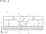
- FIG. 2 is a sectional view taken along the line A-A of FIG. 1 .
- the antenna 1 includes a flat plate-like metal member (substrate) 2 having an antenna structure, a radome 3 disposed to face a first surface 2a of the metal member 2, and a radio wave absorbing member 4 disposed between the metal member 2 and the radome 3.
- FIG. 3A is a top view of the metal member 2.
- FIG. 3B is a sectional view taken along the line A-A of FIG. 3A .
- a radiating portion 5 configured to radiate radio waves is provided on the first surface 2a of the metal member 2.
- the types of radio waves radiated from the radiating portion 5 are not particularly limited, and include, as an example, millimeter waves used in on-vehicle radars and the like.
- a circuit board 6 on which electronic components and the like are disposed is disposed on a second surface 2b of the metal member 2.
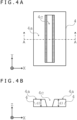
- FIG. 4A is a top view of the radio wave absorbing member 4.
- FIG. 4B is a sectional view taken along the line A-A of FIG. 4A .
- the radio wave absorbing member 4 contains a material including an insulator configured to absorb radio waves.
- the insulator material contained in the radio wave absorbing member 4 for example, polyethylene carbonate (PTC) or the like can be used.
- An opening 4c is formed in the portion corresponding to the radiating portion 5 of the metal member 2 of the radio wave absorbing member 4.
- a thickness d2 of the portion other than the portion facing the radiating portion 5 of the radome 3 is formed to a thickness less than half the waveguide wavelength ⁇ g of radio waves propagating within the radome 3, that is, d2 ⁇ g/2.
- a thickness d3 of the radio wave absorbing member 4 is formed to a thickness that is large enough for radio waves propagating within the radio wave absorbing member 4 to be absorbed by dielectric loss or magnetic loss. Specifically, the thickness d3 of the radio wave absorbing member 4 is formed to a thickness with which the intensity of radio waves leaking out from the radio wave absorbing member 4 is equal to or less than a predetermined threshold.
- the radiating portion 5 is provided to protrude on the first surface 2a of the metal member 2. Further, the portion facing the radiating portion 5 of the radome 3 is provided to protrude toward the first surface 2a of the metal member 2. Then, the radiating portion 5 and the portion facing the radiating portion 5 of the radome 3 are fitted into the opening 4c of the radio wave absorbing member 4. Further, a first surface 5a of the radiating portion 5 and a second surface 3b of the radome 3 are disposed in contact with each other.
- the radiating portion 5 has a shape that expands outward from the first surface 2a of the metal member 2.
- the portion facing the radiating portion 5 of the radome 3 also has a shape that expands outward from the first surface 2a of the metal member 2.
- An angle ⁇ formed between the radiating portion 5 and the first surface 2a of the metal member 2 is determined on the basis of the opening and directivity required for the antenna 1.
- radio waves are radiated from the radiating portion 5.
- Most of the radio waves radiated from the radiating portion 5 propagate in the Z direction in the portion with the thickness d1 of the radome 3, as indicated by the solid arrow in FIG. 5 , and pass through the interface between the first surface 3a of the radome 3 and the external air layer, to be radiated to the outside of the radome 3, that is, upward in FIG. 5 .
- the thickness d2 of the portion other than the portion facing the radiating portion 5 of the radome 3 is formed to be less than half the waveguide wavelength ⁇ g of radio waves propagating within the radome 3, that is, d2 ⁇ g/2.
- the antenna structure of the radar apparatus according to Embodiments 1 to 9 has the radiating portion provided to protrude on the first surface of the flat plate-like substrate.
- the antenna structure of the radar apparatus may be, for example, a slot antenna, a microstrip antenna, or a horn antenna.
- the radiating portion may be a space provided on the first surface of the flat plate-like substrate.
- the antenna of the radar apparatus is also applicable to any on-vehicle control system, apparatus, method, and the like described below.
- FIG. 23 is a block diagram illustrating a configuration example of a vehicle control system 11 that is an example of a mobile apparatus control system to which the present technology is applied.
- the antenna of the radar apparatus according to the embodiments or the modified examples described above can also be used as an antenna for a case where, for example, a communication unit 22 performs wireless communication.
- the vehicle control system 11 is provided in a vehicle 100 and performs processing related to the travel assistance and automated driving of the vehicle 100.
- the vehicle control system 11 includes a vehicle control ECU (Electronic Control Unit) 21, the communication unit 22, a map information accumulation unit 23, a position information acquisition unit 24, an external recognition sensor 25, an in-vehicle sensor 26, a vehicle sensor 27, a storage unit 28, the travel assistance and automated driving control unit 29, a DMS (Driver Monitoring System) 30, an HMI (Human Machine Interface) 31, and a vehicle control unit 32.
- vehicle control ECU Electronic Control Unit
- the communication unit 22 includes a vehicle control ECU (Electronic Control Unit) 21, the communication unit 22, a map information accumulation unit 23, a position information acquisition unit 24, an external recognition sensor 25, an in-vehicle sensor 26, a vehicle sensor 27, a storage unit 28, the travel assistance and automated driving control unit 29, a DMS (Driver Monitoring System) 30, an HMI (Human Machine Interface) 31, and a vehicle control unit 32.
- CAN may be applied for data related to vehicle control
- Ethernet may be applied for large-capacity data.
- each unit of the vehicle control system 11 is directly connected without the communication network 41 using wireless communication intended for relatively short-range communication, such as near field communication (NFC) or Bluetooth (registered trademark).
- NFC near field communication
- Bluetooth registered trademark
- the vehicle control ECU 21 includes, for example, various processors such as a CPU (Central Processing Unit) and an MPU (Micro Processing Unit).
- the vehicle control ECU 21 controls all or some of the functions of the vehicle control system 11.
- the communication with the outside of the vehicle that the communication unit 22 can execute is generally described.
- the communication unit 22 communicates with, for example, servers existing on external networks (hereinafter referred to as an "external server") via base stations or access points using wireless communication methods such as 5G (5th generation mobile communication system), LTE (Long Term Evolution), or DSRC (Dedicated Short Range Communications).
- the external networks with which the communication unit 22 communicates include, for example, the Internet, cloud networks, or company-specific networks.
- the communication method that the communication unit 22 performs with respect to the external networks is not particularly limited as long as it is a wireless communication method capable of digital bidirectional communication at a predetermined communication speed or higher and over a predetermined distance or longer.
- the communication unit 22 can communicate with terminals existing in the vicinity of the subject vehicle using P2P (Peer To Peer) technology.
- the terminals existing in the vicinity of the subject vehicle are, for example, terminals worn by mobile objects moving at relatively low speeds, such as pedestrians and bicycles, terminals installed at fixed positions such as stores, or MTC (Machine Type Communication) terminals.
- the communication unit 22 can also perform V2X communication.
- V2X communication refers to communication between the subject vehicle and others, such as vehicle-to-vehicle communication with other vehicles, vehicle-to-infrastructure communication with roadside units or the like, vehicle-to-home communication with homes, and vehicle-to-pedestrian communication with terminals or the like possessed by pedestrians.
- the communication unit 22 can receive, for example, programs for updating software for controlling the operation of the vehicle control system 11 from the outside (Over The Air).
- the communication unit 22 can also receive map information, traffic information, information regarding surroundings of the vehicle 100, and the like from the outside. Further, for example, the communication unit 22 can transmit information associated with the vehicle 100, information regarding surroundings of the vehicle 100, and the like to the outside. Examples of the information associated with the vehicle 100 that the communication unit 22 transmits to the outside include data indicating the state of the vehicle 100 and recognition results by a recognition unit 73.
- the communication unit 22 performs communication corresponding to vehicle emergency call systems such as eCall.
- the communication with the inside of the vehicle that the communication unit 22 can execute is generally described.
- the communication unit 22 can communicate with each piece of equipment inside the vehicle using, for example, wireless communication.
- the communication unit 22 can wirelessly communicate with equipment inside the vehicle using, for example, communication methods capable of digital bidirectional communication at a predetermined communication speed or higher via wireless communication, such as wireless LAN, Bluetooth, NFC, or WUSB (Wireless USB).
- the communication unit 22 is not limited to this and can also communicate with each piece of equipment inside the vehicle using wired communication.
- the communication unit 22 can communicate with each piece of equipment inside the vehicle via wired communication through cables connected to connection terminals, which are not illustrated.
- the communication unit 22 can communicate with each piece of equipment inside the vehicle using, for example, communication methods capable of digital bidirectional communication at a predetermined communication speed or higher via wired communication, such as USB (Universal Serial Bus), HDMI (High-Definition Multimedia Interface) (registered trademark), or MHL (Mobile High-definition Link).
- communication methods capable of digital bidirectional communication at a predetermined communication speed or higher via wired communication, such as USB (Universal Serial Bus), HDMI (High-Definition Multimedia Interface) (registered trademark), or MHL (Mobile High-definition Link).
- equipment inside the vehicle refers to, for example, equipment not connected to the communication network 41 inside the vehicle.
- equipment inside the vehicle for example, mobile equipment or wearable equipment possessed by the passenger such as a driver, information equipment brought into the vehicle and temporarily installed, or the like is assumed.
- the map information accumulation unit 23 accumulates either or both maps acquired from the outside and maps created in the vehicle 100. For example, the map information accumulation unit 23 accumulates three-dimensional high-precision maps and global maps that cover wider areas with lower precision than high-precision maps.
- Examples of the high-precision maps include dynamic maps, point cloud maps, and vector maps.
- a dynamic map is, for example, a map including four layers of dynamic information, semi-dynamic information, semi-static information, and static information, and is provided from an external server or the like to the vehicle 100.
- a point cloud map is a map including point clouds (point cloud data).
- a vector map is a map in which, for example, traffic information such as lane and traffic light positions and a point cloud map are associated and adapted for ADAS (Advanced Driver Assistance System) or AD (Autonomous Driving).
- Point cloud maps and vector maps may be provided from, for example, external servers or may be created in the vehicle 100 and accumulated in the map information accumulation unit 23 as maps for matching with local maps, which are described later, on the basis of sensing results by a camera 51, a radar 52, a LiDAR 53, or the like. Further, in a case where a high-precision map is provided from an external server or the like, in order to reduce communication capacity, for example, map data regarding several hundred meters square related to a planned route on which the vehicle 100 is to travel from now on is acquired from the external server or the like.
- the position information acquisition unit 24 receives GNSS (Global Navigation Satellite System) signals from GNSS satellites and acquires position information regarding the vehicle 100.
- the acquired position information is supplied to the travel assistance and automated driving control unit 29.
- the position information acquisition unit 24 is not limited to methods using GNSS signals and may acquire position information using beacons, for example.
- the external recognition sensor 25 includes various sensors used for recognizing the external situation of the vehicle 100 and supplies sensor data from each sensor to each unit of the vehicle control system 11.
- the external recognition sensor 25 includes any type and number of sensors.
- the external recognition sensor 25 includes the camera 51, the radar 52, the LiDAR (Light Detection and Ranging, Laser Imaging Detection and Ranging) 53, and an ultrasonic sensor 54.
- the external recognition sensor 25 is not limited to this and may include one or more types of sensors among the camera 51, the radar 52, the LiDAR 53, and the ultrasonic sensor 54.
- the numbers of the cameras 51, the radars 52, the LiDARs 53, and the ultrasonic sensors 54 are not particularly limited as long as the camera 51, the radar 52, the LiDAR 53, and the ultrasonic sensor 54 can realistically be installed in the vehicle 100.
- the types of sensors included in the external recognition sensor 25 are not limited to this example, and the external recognition sensor 25 may include other types of sensors. Examples of the sensing areas of each sensor included in the external recognition sensor 25 are described later.
- the imaging method of the camera 51 is not particularly limited.
- a camera using an imaging method capable of distance measurement such as a ToF (Time of Flight) camera, a stereo camera, a monocular camera, or an infrared camera, can be applied to the camera 51 as needed.
- the camera 51 is not limited to this and may be one for simply acquiring captured images, regardless of distance measurement.
- the external recognition sensor 25 can include an environmental sensor for detecting the environment around the vehicle 100.
- the environmental sensor is a sensor for detecting an environment such as weather, atmospheric phenomena, and brightness.
- Examples of the environmental sensor can include various sensors such as raindrop sensors, fog sensors, sunlight sensors, snow sensors, and illuminance sensors.
- the external recognition sensor 25 includes a microphone used for detecting the sound around the vehicle 100, the positions of sound sources, and the like.
- the in-vehicle sensor 26 includes various sensors for detecting information regarding the inside of the vehicle and supplies sensor data from each sensor to each unit of the vehicle control system 11.
- the types and numbers of the various sensors included in the in-vehicle sensor 26 are not particularly limited as long as the sensors can realistically be installed in the vehicle 100.
- the in-vehicle sensor 26 can include at least one or more types of sensors among cameras, radars, seat sensors, steering wheel sensors, microphones, and biosensors.
- cameras included in the in-vehicle sensor 26 for example, cameras using various imaging methods capable of distance measurement, such as ToF cameras, stereo cameras, monocular cameras, or infrared cameras can be used.
- the cameras included in the in-vehicle sensor 26 are not limited to these and may be ones for simply acquiring captured images, regardless of distance measurement.
- a biosensor included in the in-vehicle sensor 26 is provided on the seat, the steering wheel, or the like and detects various types of biometric information regarding the passenger such as a driver.
- the vehicle sensor 27 includes various sensors for detecting the state of the vehicle 100 and supplies sensor data from each sensor to each unit of the vehicle control system 11.
- the types and numbers of the various sensors included in the vehicle sensor 27 are not particularly limited as long as the sensors can realistically be installed in the vehicle 100.
- the vehicle sensor 27 includes a speed sensor, an acceleration sensor, an angular velocity sensor (gyro sensor), and an inertial measurement unit (IMU) that integrates them.
- the vehicle sensor 27 includes a steering angle sensor configured to detect the steering angle of the steering wheel, a yaw rate sensor, an accelerator sensor configured to detect the operation amount of the accelerator pedal, and a brake sensor configured to detect the operation amount of the brake pedal.
- the vehicle sensor 27 includes a rotation sensor configured to detect the number of rotations of the engine or the motor, an air pressure sensor configured to detect tire pressure, a slip ratio sensor configured to detect tire slip ratio, and a wheel speed sensor configured to detect the rotation speed of the wheels.
- the vehicle sensor 27 includes a battery sensor configured to detect the remaining amount and temperature of the battery, and an impact sensor configured to detect external impact.
- the storage unit 28 includes at least one of a nonvolatile storage medium and a volatile storage medium, and stores data and programs.
- the storage unit 28 is used as, for example, EEPROM (Electrically Erasable Programmable Read Only Memory) and RAM (Random Access Memory), and as the storage media, magnetic storage devices such as HDDs (Hard Disc Drives), semiconductor storage devices, optical storage devices, and magnetooptical storage devices can be applied.
- the storage unit 28 stores various programs and data that each unit of the vehicle control system 11 uses.
- the storage unit 28 includes an EDR (Event Data Recorder) and DSSAD (Data Storage System for Automated Driving), and stores information regarding the vehicle 100 before and after events such as accidents and information acquired by the in-vehicle sensor 26.
- EDR Event Data Recorder
- DSSAD Data Storage System for Automated Driving
- the travel assistance and automated driving control unit 29 controls the travel assistance and automated driving of the vehicle 100.
- the travel assistance and automated driving control unit 29 includes an analysis unit 61, an action planning unit 62, and an operation control unit 63.
- the analysis unit 61 performs the analysis processing of the vehicle 100 and the situation around the vehicle 100.
- the analysis unit 61 includes a self-position estimation unit 71, a sensor fusion unit 72, and the recognition unit 73.
- the self-position estimation unit 71 estimates the self-position of the vehicle 100 on the basis of sensor data from the external recognition sensor 25 and high-precision maps accumulated in the map information accumulation unit 23. For example, the self-position estimation unit 71 generates a local map on the basis of sensor data from the external recognition sensor 25 and matches the local map with the high-precision map, thereby estimating the self-position of the vehicle 100.
- the reference of the position of the vehicle 100 is, for example, the center of the rear wheel pair axle.
- a local map is, for example, a three-dimensional high-precision map created using a technology such as SLAM (Simultaneous Localization and Mapping) or an occupancy grid map.
- a three-dimensional high-precision map is, for example, a point cloud map as described above.
- An occupancy grid map is a map that divides the three-dimensional or two-dimensional space around the vehicle 100 into grids (lattices) of a predetermined size and indicates the occupied state of an object in grid units. The occupied state of an object is indicated by, for example, the presence, absence, or existence probability of the object.
- the local map is also used for, for example, the detection processing and the recognition processing of the external situation of the vehicle 100 by the recognition unit 73.
- the self-position estimation unit 71 may estimate the self-position of the vehicle 100 on the basis of position information acquired by the position information acquisition unit 24 and sensor data from the vehicle sensor 27.
- the sensor fusion unit 72 combines multiple different types of sensor data (for example, image data supplied from the camera 51 and sensor data supplied from the radar 52), thereby performing sensor fusion processing to obtain new information. Examples of the method of combining different types of sensor data include integration, fusion, and association.
- the recognition unit 73 executes detection processing to detect the external situation of the vehicle 100 and recognition processing to recognize the external situation of the vehicle 100.
- the recognition unit 73 performs the detection processing and the recognition processing of the external situation of the vehicle 100 on the basis of information from the external recognition sensor 25, information from the self-position estimation unit 71, information from the sensor fusion unit 72, and the like.
- the recognition unit 73 performs the detection processing, the recognition processing, and the like of objects around the vehicle 100.
- Object detection processing refers to, for example, the processing of detecting the presence or absence, sizes, shapes, positions, movement, and the like of objects.
- Object recognition processing refers to, for example, the processing of recognizing attributes such as the types of objects or of identifying specific objects.
- the detection processing and the recognition processing are not necessarily clearly separated and overlap in some cases.
- the recognition unit 73 performs clustering to classify point clouds based on sensor data from the radar 52, the LiDAR 53, or the like into clusters of points, thereby detecting objects around the vehicle 100. With this, the presence or absence, sizes, shapes, and positions of objects around the vehicle 100 are detected.
- the recognition unit 73 performs tracking to follow the movement of clusters of points classified by clustering, thereby detecting the movement of the objects around the vehicle 100. With this, the speed and directions of travel (movement vectors) of objects around the vehicle 100 are detected.
- the recognition unit 73 detects or recognizes vehicles, people, bicycles, obstacles, structures, roads, traffic lights, traffic signs, road markings, and the like on the basis of image data supplied from the camera 51. Further, the recognition unit 73 may perform recognition processing such as semantic segmentation to recognize the types of objects around the vehicle 100.
- the recognition unit 73 can perform the recognition processing of traffic rules around the vehicle 100 on the basis of maps accumulated in the map information accumulation unit 23, the result of self-position estimation by the self-position estimation unit 71, and the recognition results of objects around the vehicle 100 by the recognition unit 73. Through this processing, the recognition unit 73 can recognize the positions and states of traffic lights, the content of traffic signs and road markings, the content of traffic regulations, drivable lanes, and the like.
- the recognition unit 73 can perform the recognition processing of the environment around the vehicle 100.
- the surrounding environment that the recognition unit 73 recognizes weather, temperature, humidity, brightness, road surface conditions, and the like are assumed.
- the action planning unit 62 creates action plans for the vehicle 100. For example, the action planning unit 62 performs route planning and route following processing to create action plans.
- route planning refers to the processing of planning a rough route from start to goal.
- This route planning also includes what is called trajectory planning, which is the processing of considering the motion characteristics of the vehicle 100 and generating a trajectory on the planned route that allows for safe and smooth driving in the vicinity of the vehicle 100 (Local path planning).
- Route following refers to the processing of planning operations to drive safely and accurately along a route planned by route planning within the planned time.
- the action planning unit 62 can calculate the target speed and the target angular velocity of the vehicle 100.
- the operation control unit 63 controls the operation of the vehicle 100 to achieve action plans created by the action planning unit 62.
- the operation control unit 63 controls a steering control unit 81, a brake control unit 82, and a drive control unit 83 included in the vehicle control unit 32, which are described later, to perform acceleration/deceleration control and direction control such that the vehicle 100 travels along a trajectory calculated by trajectory planning.
- the operation control unit 63 performs cooperative control for the purpose of achieving ADAS functions such as collision avoidance or impact mitigation, following driving, speed maintenance driving, collision warning for the subject vehicle, and lane departure warning for the subject vehicle.
- the operation control unit 63 performs cooperative control for the purpose of, for example, automated driving, which allows the vehicle to autonomously travel independently of the operation of the driver.
- the DMS 30 performs the authentication processing of the driver, the recognition processing of the state of the driver, and the like on the basis of sensor data from the in-vehicle sensor 26, input data input to the HMI 31, which is described later, and the like.
- the state of the driver to be recognized for example, the physical condition, alertness level, concentration level, fatigue level, line-of-sight direction, drunkenness level, driving operation, posture, and the like of the driver are assumed.
- the DMS 30 may perform the authentication processing of a passenger other than the driver and the recognition processing of the state of the passenger. Further, for example, the DMS 30 may perform the recognition processing of the situation inside the vehicle on the basis of sensor data from the in-vehicle sensor 26. As the situation inside the vehicle to be recognized, for example, temperature, humidity, brightness, and odor are assumed.
- the HMI 31 performs the input of various types of data, instructions, and the like, and the presentation of various types of data to the driver and the like.
- the input of data by the HMI 31 is generally described.
- the HMI 31 includes input devices for people to input data.
- the HMI 31 generates input signals on the basis of data, instructions, and the like input by the input devices and supplies the input signals to each unit of the vehicle control system 11.
- the HMI 31 includes, as input devices, operating elements such as a touch panel, a button, a switch, and a lever.
- the HMI 31 is not limited to this and may further include input devices that support the input of information by methods other than manual operation, such as voice or gestures.
- the HMI 31 may use, for example, remote control apparatuses utilizing infrared or radio waves, or external connection equipment such as mobile equipment or wearable equipment compatible with the operation of the vehicle control system 11 as input devices.
- the presentation of data by the HMI 31 is generally described.
- the HMI31 generates visual information, auditory information, and tactile information regarding the passenger or the outside of the vehicle. Further, the HMI 31 performs output control to control the output, the output content, the output timing, the output method, and the like of each piece of generated information.
- the HMI 31 generates and outputs, as visual information, for example, information indicated by images or lights, such as operation screens, the state display of the vehicle 100, warning displays, and monitor images indicating the situation around the vehicle 100.
- the HMI 31 generates and outputs, as auditory information, for example, information indicated by sounds, such as voice guidance, warning sounds, and warning messages.
- the HMI 31 generates and outputs, as tactile information, for example, information that is given to the sense of touch of the passenger through force, vibration, movement, or the like.
- the output device for the HMI 31 to output visual information for example, a display apparatus configured to present visual information by displaying images by itself, or a projector apparatus configured to present visual information by projecting images can be applied.
- the display apparatus may be, other than a display apparatus having a normal display, for example, an apparatus configured to display visual information within the field of view of the passenger, such as a head-up display, a transmissive display, or a wearable device with an AR (Augmented Reality) function.
- the HMI 31 can also use a display device included in a navigation device, an instrument panel, a CMS (Camera Monitoring System), an electronic mirror, lamps, or the like, which are provided in the vehicle 100, as an output device configured to output visual information.
- CMS Cara Monitoring System
- the output device for the HMI 31 to output auditory information for example, an audio speaker, headphones, earphones, or the like can be applied.
- haptic elements using haptic technology can be applied.
- the haptic elements are provided in parts of the vehicle 100 with which the passenger comes into contact, such as the steering wheel and the seats.
- the vehicle control unit 32 controls each unit of the vehicle 100.
- the vehicle control unit 32 includes the steering control unit 81, the brake control unit 82, the drive control unit 83, a body control unit 84, a light control unit 85, and a horn control unit 86.
- the steering control unit 81 detects and controls the state of the steering system of the vehicle 100, for example.
- the steering system includes, for example, a steering mechanism including a steering wheel and the like, and electric power steering.
- the steering control unit 81 includes, for example, a steering ECU configured to control the steering system, and an actuator configured to drive the steering system.
- the brake control unit 82 detects and controls the state of the brake system of the vehicle 100, for example.
- the brake system includes, for example, a brake mechanism including a brake pedal and the like, an ABS (Antilock Brake System), and a regenerative brake mechanism.
- the brake control unit 82 includes, for example, a brake ECU configured to control the brake system, and an actuator configured to drive the brake system.
- the drive control unit 83 detects and controls the state of the drive system of the vehicle 100, for example.
- the drive system includes, for example, an accelerator pedal, a drive force generation apparatus for generating drive force, such as an internal combustion engine or a drive motor, and a drive force transmission mechanism for transmitting drive force to wheels.
- the drive control unit 83 includes, for example, a drive ECU configured to control the drive system, and an actuator configured to drive the drive system.
- the body control unit 84 detects and controls the state of the body system of the vehicle 100, for example.
- the body system includes, for example, a keyless entry system, a smart key system, a power window apparatus, power seats, an air conditioning apparatus, airbags, seatbelts, and a shift lever.
- the body control unit 84 includes, for example, a body system ECU configured to control the body system, and an actuator configured to drive the body system.
- the horn control unit 86 detects and controls the state of the car horn of the vehicle 100, for example.
- the horn control unit 86 includes, for example, a horn ECU configured to control the car horn, and an actuator configured to drive the car horn.
- FIG. 24 is a view illustrating examples of the sensing areas of the camera 51, the radar 52, the LiDAR 53, the ultrasonic sensor 54, and the like of the external recognition sensor 25 in FIG. 23 .
- FIG. 24 schematically illustrates the vehicle 100 as viewed from above, with the left end side corresponding to the front end (front) side of the vehicle 100, and with the right end side corresponding to the rear end (rear) side of the vehicle 100.
- Sensing results in the sensing area 101F and the sensing area 101B are used for, for example, the parking assistance of the vehicle 100.
- Sensing results in the sensing area 102F are used for, for example, detecting vehicles, pedestrians, and the like located in front of the vehicle 100.
- Sensing results in the sensing area 102B are used for, for example, the function of preventing collision at the rear of the vehicle 100.
- Sensing results in the sensing area 102L and the sensing area 102R are used for, for example, detecting objects in blind spots on the lateral sides of the vehicle 100.
- a sensing area 104 indicates an example of the sensing area of the LiDAR 53.
- the sensing area 104 covers positions farther than the sensing area 103F in front of the vehicle 100.
- the sensing area 104 has a narrower range in the left-right direction than the sensing area 103F.
- Sensing results in the sensing area 104 are used for, for example, detecting objects such as surrounding vehicles.
- Sensing results in the sensing area 105 are used for, for example, ACC (Adaptive Cruise Control), emergency braking, and collision avoidance.
- ACC Adaptive Cruise Control
- emergency braking emergency braking
- collision avoidance collision avoidance
- each sensor including the camera 51, the radar 52, the LiDAR 53, and the ultrasonic sensor 54, which are included in the external recognition sensor 25, may have various configurations other than those in FIG. 24 .
- the ultrasonic sensor 54 may also sense the lateral sides of the vehicle 100, and the LiDAR 53 may sense the rear of the vehicle 100.
- the installation positions of each sensor are not limited to the respective examples described above. Further, the number of each sensor may be one or plural.
- a radar apparatus including:
- a thickness of a portion other than a portion facing the radiating portion of the radome is less than half a waveguide wavelength of a radio wave propagating within the radome.
- a thickness of a portion facing the radiating portion of the radome includes an integer multiple of half a waveguide wavelength of a radio wave propagating within the radome.
- the radar apparatus according to any one of Items 1 to 5, in which the radio wave absorbing member and the radome are disposed in contact with each other.
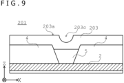
- the radar apparatus according to any one of Items 1 to 6, in which a recessed portion or a protruding portion is formed on the first surface of the radome.
- the radar apparatus in which the radio wave absorbing member is disposed in one or multiple ring shapes at the periphery of the radiating portion.
- the radar apparatus in which a cushioning member is disposed between the substrate and the radome, except in a portion in which the radio wave absorbing member is disposed.
- the radar apparatus according to any one of Items 1 to 9, in which the radio wave absorbing member includes multiple layers of radio wave absorbing members with different materials.
- one of the multiple layers of radio wave absorbing members with different materials includes an air layer.
- the radar apparatus according to any one of Items 1 to 12, in which the multiple radiating portions are provided on the first surface of the substrate.
- the radar apparatus according to any one of Items 1 to 13, in which the insulator included in the radio wave absorbing member includes polyethylene carbonate.
- the radar apparatus according to any one of Items 1 to 14, in which the antenna structure includes any one of a slot antenna, a microstrip antenna, or a horn antenna.
- the radar apparatus according to any one of Items 1 to 15, in which a frequency selective surface and a metasurface are disposed on the first surface of the radome.
- the radar apparatus according to any one of Items 1 to 16, in which the radio wave radiated from the radiating portion includes a millimeter wave.
- the radar apparatus according to any one of Items 1 to 17, in which the radar apparatus includes an on-vehicle radar apparatus.
- the radar apparatus according to any one of Items 1 to 18, in which the radiating portion includes a space provided on the first surface of the substrate.
- the radar apparatus in which the substrate includes a metal member.
- the radar apparatus according to any one of Items 1 to 20, in which a feed line configured to feed the antenna structure is provided on a second surface opposite to the first surface of the substrate.
- the radar apparatus in which an electronic component is disposed on the second surface of the substrate.
- the radar apparatus in which a heat dissipation member is provided to face the second surface of the substrate.
- An on-vehicle sensing system including:
Landscapes
- Engineering & Computer Science (AREA)
- Radar, Positioning & Navigation (AREA)
- Remote Sensing (AREA)
- Physics & Mathematics (AREA)
- Computer Networks & Wireless Communication (AREA)
- General Physics & Mathematics (AREA)
- Electromagnetism (AREA)
- Computer Security & Cryptography (AREA)
- Radar Systems Or Details Thereof (AREA)
Applications Claiming Priority (3)
| Application Number | Priority Date | Filing Date | Title |
|---|---|---|---|
| JP2022138722 | 2022-08-31 | ||
| JP2022175728 | 2022-11-01 | ||
| PCT/JP2023/031595 WO2024048671A1 (ja) | 2022-08-31 | 2023-08-30 | レーダ装置および車載センシングシステム |
Publications (2)
| Publication Number | Publication Date |
|---|---|
| EP4582831A1 true EP4582831A1 (de) | 2025-07-09 |
| EP4582831A4 EP4582831A4 (de) | 2025-11-12 |
Family
ID=90099785
Family Applications (1)
| Application Number | Title | Priority Date | Filing Date |
|---|---|---|---|
| EP23860433.4A Pending EP4582831A4 (de) | 2022-08-31 | 2023-08-30 | Radarvorrichtung und fahrzeugmontiertes sensorsystem |
Country Status (5)
| Country | Link |
|---|---|
| US (1) | US20260063754A1 (de) |
| EP (1) | EP4582831A4 (de) |
| JP (1) | JPWO2024048671A1 (de) |
| CN (1) | CN119744359A (de) |
| WO (1) | WO2024048671A1 (de) |
Family Cites Families (11)
| Publication number | Priority date | Publication date | Assignee | Title |
|---|---|---|---|---|
| FR2729791B1 (fr) * | 1988-06-14 | 1997-05-16 | Thomson Csf | Dispositif pour diminuer l'effet de radome avec une antenne large bande a rayonnement de surface, et diminuer la surface equivalente refelchissante de l'ensemble |
| JP2516293Y2 (ja) * | 1991-04-24 | 1996-11-06 | 三菱電機株式会社 | アレーアンテナ装置 |
| JP3419675B2 (ja) * | 1998-02-10 | 2003-06-23 | 三菱電機株式会社 | 車載用電波レーダ装置 |
| JP2004325160A (ja) * | 2003-04-23 | 2004-11-18 | Hitachi Ltd | 車載用レーダ |
| JP2007074662A (ja) * | 2005-09-09 | 2007-03-22 | Hitachi Ltd | ミリ波レーダ装置 |
| US9653796B2 (en) * | 2013-12-16 | 2017-05-16 | Valeo Radar Systems, Inc. | Structure and technique for antenna decoupling in a vehicle mounted sensor |
| DE102014010383A1 (de) * | 2014-07-12 | 2016-01-14 | Audi Ag | Radom für eine Radarsensoreinrichtung mit wenigstens zwei Radarsensoren und Radarsensoreinrichtung |
| JP6363528B2 (ja) * | 2015-02-09 | 2018-07-25 | 株式会社デンソー | レーダ装置搭載構造 |
| CN108400440A (zh) * | 2018-01-17 | 2018-08-14 | 华域汽车系统股份有限公司 | 一种适用于车载毫米波雷达的宽角度天线罩及天线装置 |
| JP7163209B2 (ja) * | 2019-02-06 | 2022-10-31 | 日立Astemo株式会社 | レーダ装置 |
| CN111697333A (zh) * | 2020-06-01 | 2020-09-22 | 东风汽车集团有限公司 | 一种超材料天线罩 |
-
2023
- 2023-08-30 US US19/105,191 patent/US20260063754A1/en active Pending
- 2023-08-30 CN CN202380061250.3A patent/CN119744359A/zh active Pending
- 2023-08-30 JP JP2024544344A patent/JPWO2024048671A1/ja active Pending
- 2023-08-30 WO PCT/JP2023/031595 patent/WO2024048671A1/ja not_active Ceased
- 2023-08-30 EP EP23860433.4A patent/EP4582831A4/de active Pending
Also Published As
| Publication number | Publication date |
|---|---|
| US20260063754A1 (en) | 2026-03-05 |
| EP4582831A4 (de) | 2025-11-12 |
| WO2024048671A1 (ja) | 2024-03-07 |
| JPWO2024048671A1 (de) | 2024-03-07 |
| CN119744359A (zh) | 2025-04-01 |
Similar Documents
| Publication | Publication Date | Title |
|---|---|---|
| US12560697B2 (en) | Information processing device, and information processing method | |
| US20230267746A1 (en) | Information processing device, information processing method, and program | |
| WO2023013405A1 (en) | Antenna device, radar device and vehicle control system | |
| US20240426997A1 (en) | Information processing apparatus, information processing method, and information processing system | |
| WO2022239348A1 (ja) | レーダ装置、信号処理方法、及びプログラム | |
| US20240012108A1 (en) | Information processing apparatus, information processing method, and program | |
| KR20260040015A (ko) | 전자 기기 및 레이다 장치 | |
| EP4475332A1 (de) | Antennenvorrichtung, radarvorrichtung und übertragungsvorrichtung | |
| EP4582831A1 (de) | Radarvorrichtung und fahrzeugmontiertes sensorsystem | |
| US20240019539A1 (en) | Information processing device, information processing method, and information processing system | |
| WO2025154646A1 (ja) | アンテナ装置及びレーダ装置 | |
| US20250102657A1 (en) | Information processing system, information processing apparatus, and information processing method | |
| US20250067875A1 (en) | Information processing apparatus, information processing method, and information processing program | |
| US20250131824A1 (en) | Information processing device, information processing method, and information processing program | |
| WO2025173450A1 (ja) | アンテナ装置及びレーダ装置 | |
| US20240224359A1 (en) | Communication device, communication method, and vehicle | |
| EP4657152A1 (de) | Fahrzeugmontierte kamera | |
| JP2024164574A (ja) | 判定装置、判定方法、判定プログラム及びレーダ装置 | |
| CN121773351A (zh) | 信息处理装置、信息处理方法和雷达装置 |
Legal Events
| Date | Code | Title | Description |
|---|---|---|---|
| STAA | Information on the status of an ep patent application or granted ep patent |
Free format text: STATUS: THE INTERNATIONAL PUBLICATION HAS BEEN MADE |
|
| PUAI | Public reference made under article 153(3) epc to a published international application that has entered the european phase |
Free format text: ORIGINAL CODE: 0009012 |
|
| STAA | Information on the status of an ep patent application or granted ep patent |
Free format text: STATUS: REQUEST FOR EXAMINATION WAS MADE |
|
| 17P | Request for examination filed |
Effective date: 20250324 |
|
| AK | Designated contracting states |
Kind code of ref document: A1 Designated state(s): AL AT BE BG CH CY CZ DE DK EE ES FI FR GB GR HR HU IE IS IT LI LT LU LV MC ME MK MT NL NO PL PT RO RS SE SI SK SM TR |
|
| RAP3 | Party data changed (applicant data changed or rights of an application transferred) |
Owner name: SONY GROUP CORPORATION Owner name: SONY SEMICONDUCTOR SOLUTIONS CORPORATION |
|
| REG | Reference to a national code |
Ref country code: DE Ref legal event code: R079 Free format text: PREVIOUS MAIN CLASS: G01S0007030000 Ipc: H01Q0001420000 |
|
| A4 | Supplementary search report drawn up and despatched |
Effective date: 20251010 |
|
| RIC1 | Information provided on ipc code assigned before grant |
Ipc: H01Q 1/42 20060101AFI20251006BHEP Ipc: H01Q 17/00 20060101ALI20251006BHEP Ipc: H01Q 1/32 20060101ALI20251006BHEP Ipc: G01S 7/03 20060101ALI20251006BHEP Ipc: G01S 7/02 20060101ALI20251006BHEP Ipc: G01S 13/931 20200101ALI20251006BHEP |
|
| DAV | Request for validation of the european patent (deleted) | ||
| DAX | Request for extension of the european patent (deleted) |