EP4582788A1 - Device and method for measuring turbidity - Google Patents
Device and method for measuring turbidity Download PDFInfo
- Publication number
- EP4582788A1 EP4582788A1 EP22963608.9A EP22963608A EP4582788A1 EP 4582788 A1 EP4582788 A1 EP 4582788A1 EP 22963608 A EP22963608 A EP 22963608A EP 4582788 A1 EP4582788 A1 EP 4582788A1
- Authority
- EP
- European Patent Office
- Prior art keywords
- light receiving
- light
- fluid
- turbidity
- light source
- Prior art date
- Legal status (The legal status is an assumption and is not a legal conclusion. Google has not performed a legal analysis and makes no representation as to the accuracy of the status listed.)
- Pending
Links
Images





Classifications
-
- G—PHYSICS
- G01—MEASURING; TESTING
- G01N—INVESTIGATING OR ANALYSING MATERIALS BY DETERMINING THEIR CHEMICAL OR PHYSICAL PROPERTIES
- G01N21/00—Investigating or analysing materials by the use of optical means, i.e. using sub-millimetre waves, infrared, visible or ultraviolet light
- G01N21/17—Systems in which incident light is modified in accordance with the properties of the material investigated
- G01N21/47—Scattering, i.e. diffuse reflection
- G01N21/49—Scattering, i.e. diffuse reflection within a body or fluid
- G01N21/51—Scattering, i.e. diffuse reflection within a body or fluid inside a container, e.g. in an ampoule
-
- G—PHYSICS
- G01—MEASURING; TESTING
- G01N—INVESTIGATING OR ANALYSING MATERIALS BY DETERMINING THEIR CHEMICAL OR PHYSICAL PROPERTIES
- G01N15/00—Investigating characteristics of particles; Investigating permeability, pore-volume or surface-area of porous materials
- G01N15/06—Investigating concentration of particle suspensions
-
- G—PHYSICS
- G01—MEASURING; TESTING
- G01N—INVESTIGATING OR ANALYSING MATERIALS BY DETERMINING THEIR CHEMICAL OR PHYSICAL PROPERTIES
- G01N15/00—Investigating characteristics of particles; Investigating permeability, pore-volume or surface-area of porous materials
- G01N15/06—Investigating concentration of particle suspensions
- G01N15/075—Investigating concentration of particle suspensions by optical means
-
- G—PHYSICS
- G01—MEASURING; TESTING
- G01N—INVESTIGATING OR ANALYSING MATERIALS BY DETERMINING THEIR CHEMICAL OR PHYSICAL PROPERTIES
- G01N21/00—Investigating or analysing materials by the use of optical means, i.e. using sub-millimetre waves, infrared, visible or ultraviolet light
- G01N21/17—Systems in which incident light is modified in accordance with the properties of the material investigated
- G01N21/47—Scattering, i.e. diffuse reflection
- G01N21/49—Scattering, i.e. diffuse reflection within a body or fluid
-
- G—PHYSICS
- G01—MEASURING; TESTING
- G01N—INVESTIGATING OR ANALYSING MATERIALS BY DETERMINING THEIR CHEMICAL OR PHYSICAL PROPERTIES
- G01N33/00—Investigating or analysing materials by specific methods not covered by groups G01N1/00 - G01N31/00
- G01N33/18—Water
-
- G—PHYSICS
- G01—MEASURING; TESTING
- G01N—INVESTIGATING OR ANALYSING MATERIALS BY DETERMINING THEIR CHEMICAL OR PHYSICAL PROPERTIES
- G01N33/00—Investigating or analysing materials by specific methods not covered by groups G01N1/00 - G01N31/00
- G01N33/18—Water
- G01N33/186—Water using one or more living organisms, e.g. a fish
- G01N33/1866—Water using one or more living organisms, e.g. a fish using microorganisms
-
- G—PHYSICS
- G01—MEASURING; TESTING
- G01N—INVESTIGATING OR ANALYSING MATERIALS BY DETERMINING THEIR CHEMICAL OR PHYSICAL PROPERTIES
- G01N21/00—Investigating or analysing materials by the use of optical means, i.e. using sub-millimetre waves, infrared, visible or ultraviolet light
- G01N21/17—Systems in which incident light is modified in accordance with the properties of the material investigated
- G01N21/47—Scattering, i.e. diffuse reflection
- G01N21/49—Scattering, i.e. diffuse reflection within a body or fluid
- G01N21/51—Scattering, i.e. diffuse reflection within a body or fluid inside a container, e.g. in an ampoule
- G01N2021/513—Cuvettes for scattering measurements
-
- G—PHYSICS
- G01—MEASURING; TESTING
- G01N—INVESTIGATING OR ANALYSING MATERIALS BY DETERMINING THEIR CHEMICAL OR PHYSICAL PROPERTIES
- G01N21/00—Investigating or analysing materials by the use of optical means, i.e. using sub-millimetre waves, infrared, visible or ultraviolet light
- G01N21/17—Systems in which incident light is modified in accordance with the properties of the material investigated
- G01N21/47—Scattering, i.e. diffuse reflection
- G01N21/49—Scattering, i.e. diffuse reflection within a body or fluid
- G01N21/53—Scattering, i.e. diffuse reflection within a body or fluid within a flowing fluid, e.g. smoke
- G01N21/532—Scattering, i.e. diffuse reflection within a body or fluid within a flowing fluid, e.g. smoke with measurement of scattering and transmission
-
- G—PHYSICS
- G01—MEASURING; TESTING
- G01N—INVESTIGATING OR ANALYSING MATERIALS BY DETERMINING THEIR CHEMICAL OR PHYSICAL PROPERTIES
- G01N2201/00—Features of devices classified in G01N21/00
- G01N2201/12—Circuits of general importance; Signal processing
- G01N2201/124—Sensitivity
- G01N2201/1241—Multirange
-
- G—PHYSICS
- G01—MEASURING; TESTING
- G01N—INVESTIGATING OR ANALYSING MATERIALS BY DETERMINING THEIR CHEMICAL OR PHYSICAL PROPERTIES
- G01N2201/00—Features of devices classified in G01N21/00
- G01N2201/12—Circuits of general importance; Signal processing
- G01N2201/124—Sensitivity
- G01N2201/1248—Validating from signal shape, slope, peak
Definitions
- the present disclosure relates to a device and method for measuring turbidity of water used in home appliances.
- Turbidity refers to a concentration of light-scattering particles or light-absorbing particles suspended in a fluid. When the turbidity increases in the fluid, light transmittance can vary depending on a distribution of suspended particles in the fluid, a refractive index, surface properties, etc.
- Such turbidity information of water can be used to minimize waste of water, electricity, detergent, etc. by changing a washing cycle or purification cycle of home appliances, and to provide drinking water purified under optimal conditions, or to provide items such as tableware and clothing washed under optimal conditions.
- An object of the present disclosure is to solve the above-mentioned problems and other problems.
- An object of the present disclosure is to provide a device and method for measuring turbidity, which are capable of enabling broadband sensing for measuring water quality from a low turbidity region to a high turbidity region by amplifying a low turbidity optical signal using a reflector.
- a device for measuring turbidity can include: a fluid storage part including a reflector; a first light source configured to emit light to a fluid within the fluid storage part; a first light receiving part configured to receive scattered light scattered by suspended particles in the fluid; and a control part configured to measure turbidity of the fluid by controlling the first light source and the first light receiving part, wherein the first light source and the first light receiving part are disposed to be spaced a predetermined angle from each other around the fluid storage part in the vicinity of the fluid storage part, and the reflector is disposed between a first surface facing the first light source and a second surface facing the first light receiving part on a surface of the fluid storage part.
- the device can further include a second light source configured to emit light to the fluid within the fluid storage part, wherein the second light source can be spaced a predetermined angle from the first light source around the fluid storage part and disposed to face the first light receiving part.
- control part can be configured to: receive a first light receiving signal of the first light receiving part when the first light source is turned on, and the second light source is turned off; receive a second light receiving signal of the first light receiving part when the first light source is turned off, and the second light source is turned on; and measure the turbidity of the fluid on the basis of the first light receiving signal and the second light receiving signal.
- control part when the turbidity of the fluid is measured, can be configured to classify the turbidity of the fluid into a high turbidity region to measure a high turbidity value of the fluid on the basis of the second light receiving signal when there is no change in the first light receiving signal due to a saturation state of the first light receiving part, and the second light receiving signal is normally received.
- the fluid storage part 100 can have a pipe shape having a through-hole defined therein so that the fluid can flow, but this is only an example and is not limited thereto.
- the reflector 200 can amplify the scattered light by reflecting or re-reflecting the scattered light onto the suspended particles 120 of the fluid 110.
- a length of the reflector 200 can be less than or equal to a length of the fluid storage part 100, and a width of the reflector 200 can be less than or equal to a width between the first surface of the fluid storage part 100 facing the first light source 310 and the second surface of the fluid storage part 100 facing the light receiving part 400.
- the first light source 310 and the light receiving part 400 can be disposed to be spaced a predetermined angle from each other around the fluid storage part 100 by using the fluid storage part 100 as a center.
- the first light source 310 and the light receiving part 400 can be disposed in a direction perpendicular to each other by using the fluid storage part 100 as the center.
- the second light source 320 can be disposed to be spaced a predetermined angle from the first light source 310 around the fluid storage part 100 and face the light receiving part 400.
- the second light source 320 can be perpendicular to the first light source 310 with respect to the fluid storage part 100.
- the second light source 320 and the light receiving part 400 can be disposed symmetrically at both sides of the fluid storage part 100 along a line passing through a center point of the fluid storage part 100.
- the second light source 320 can be disposed on a second line having a predetermined angle with respect to the first line while passing through the center point of the fluid storage part 100 when the first light source 310 is disposed on the first line passing through the center point of the fluid storage part 100.
- a light output intensity of the second light source 320 can be the same as a light output intensity of the first light source 310.
- each of the first light source 310 and the second light source 320 can include a light-emitting diode, but this is only one embodiment and is not limited thereto.
- control part 500 can alternately switch the first light source 310 and the second light source 320 so that, when the first light source 310 is turned on, the second light source 320 is turned off, or when the first light source 310 is turned off, the second light source 320 is turned on.
- control part 500 can receive a first light receiving signal of the light receiving part 400 when the first light source 310 is turned on, and the second light source 320 is turned off, receive a second light receiving signal of the light receiving part 400 when the first light source 310 is turned off, and the second light source 320 is turned on, and measure the turbidity of the fluid 110 on the basis of the first light receiving signal and the second light receiving signal.
- the first light receiving signal of the light receiving part 400 can be a light receiving signal generated on the basis of a plurality of scattered light including first scattered light 210 in which light emitted from the first light source 310 is primarily scattered by the suspended particles 120 of the fluid 110, the reflected light 230 in which the first scattered light 210 is reflected or re-reflected by the reflector 200, and second scattered light 220 in which the second scattered light is secondarily scattered by the suspended particles 120 of the fluid 110.
- the second light receiving signal of the light receiving part 400 can be a light receiving signal generated on the basis of the first scattered light 210 in which the light emitted from the second light source 320 is primarily scattered by the suspended particles 120 of the fluid 110.
- control part 500 can measure the turbidity value of the fluid 110 within a range exceeding 1 NTU (Nethelometric Paultity part) and less than 2,000 NTU on the basis of the second light receiving signal when measuring the turbidity value of the fluid 110.
- 1 NTU Nethelometric Paultity part
- the light source and the reflector 200 can be fixed, and the light receiving part 400 can be disposed at a specific position at which the turbidity variation and the low turbidity distinction are maximized, or the light source and the light receiving part 400 can be fixed, and the reflector 200 can be disposed at a specific position at which the turbidity variation and the low turbidity distinction are maximized.
- the unnecessary replacement costs can be reduced by setting the customized filter replacement cycle according to the pollution standard.
- the present disclosure can be applied to the home appliances such as the water purifiers and the dishwashers that utilize the various water qualities with the broadband sensing function.
- the low-price sensor can be provided and be expanded to the various home appliances.
- the present disclosure can provide the water quality control and the customer assurance service through the real-time water quality monitoring and measurement.
- FIGS. 3 to 5 are views for explaining the fluid storage part of the device for measuring the turbidity according to an embodiment of the present disclosure.
- the fluid storage part 100 can have a cylindrical shape in which the fluid is stored.
- the fluid storage part 100 can have a pipe shape having a through-hole defined therein so that the fluid can flow, but this is only an example and is not limited thereto.
- an entire surface of the fluid storage part 100 can be provided as a light-transmitting member.
- the reason is to allow the first light 312 emitted from the first light source disposed at the outside and the second light 322 emitted from the second light source disposed at the outside to be incident into the internal fluid of the fluid storage part 100 so as to receive the internal scattered light into the external light receiving part.
- the reflector 200 can be disposed between a first surface facing the first light source and a second surface facing the light receiving part on the fluid storage part 100.
- the reflector 200 can amplify the scattered light by reflecting or re-reflecting the scattered light scattered by the suspended particles 120 inside the fluid storage part 100 toward the suspended particles 120 inside the fluid storage part 100.
- the plurality of scattered light including the first scattered light 210, in which the first light 312 emitted from the first light source is primarily scattered by the suspended particles 120 of the fluid, and the second scattered light 220 in which the reflected light 230, in which the first scattered light 210 is reflected or re-reflected by the reflector 200, is secondarily scattered by suspended particles 120 of the fluid 110 can be emitted to the external light receiving part.
- the first scattered light 210 in which the second light 322 emitted from the second light source is primarily scattered by the suspended particles 120 of the fluid, can be emitted to the external light receiving part.
- only some surfaces of the fluid storage part 100 can be provided as a light-transmitting member.
- the light-transmitting member 150 can be disposed only on the incident surface, through which the first light 312 and the second light 322 are incident inward from the outside, and the emission surface, through which the first and second scattered light 210 and 220 are emitted to the outside, and an opaque member 160 can be disposed on the remaining area.
- the reflector 200 can be attached to an inner surface of the fluid storage part 100.
- the light-transmitting member 150 can be disposed only on the incident surface, through which the first light 312 and the second light 322 are incident inward from the outside, the emission surface, through which the first and second scattered light 210 and 220 are emitted to the outside, and the attachment surface to which the reflector 200 is attached, and the opaque member 160 can be disposed on the remaining area.
- the reflector 200 can be attached to an outer surface of the fluid storage part 100.
- FIG. 6 is a view for explaining a reflector of the device for measuring the turbidity according to an embodiment of the present disclosure.
- the reflector 200 can amplify the scattered light by reflecting or re-reflecting the scattered light scattered by the suspended particles inside the fluid storage part 100 toward the suspended particles inside the fluid storage part 100.
- the reflector 200 can maximize light reflection characteristics of low turbidity particles with low light scattering.
- the reflector 200 can be disposed between a first surface facing the first light source and a second surface facing the light receiving part on the fluid storage part 100.
- the reflector 200 when the reflector 200 is disposed on an area between the first surface facing the first light source and the second surface facing the light receiving part on the surface of the fluid storage part 100, the light receiving signal of the light receiving part, by which the turbidity variation and the low turbidity distinction are maximized, can be obtained.
- water quality in a low turbidity region can be accurately measured by analyzing the light receiving signal of the light receiving part, by which the turbidity variation and the low turbidity distinction are maximized.
- FIG. 7 is a view for explaining a method for measuring turbidity in the device for measuring the turbidity according to an embodiment of the present disclosure.
- the present disclosure can include the control part 500 that controls the first light source 310, the second light source 320, and the light receiving part 400 to measure the turbidity of the fluid.
- control part 500 can alternately switch the first light source 310 and the second light source 320 so that, when the first light source 310 is turned on, the second light source 320 is turned off, or when the first light source 310 is turned off, the second light source 320 is turned on.
- control part 500 can receive the first light receiving signal of the light receiving part 400 when the first light source 310 is turned on, and the second light source 320 is turned off, receive the second light receiving signal of the light receiving part 400 when the first light source 310 is turned off, and the second light source 320 is turned on, and measure the turbidity of the fluid on the basis of the first light receiving signal and the second light receiving signal.
- control part 500 can classify the turbidity of the fluid into a high turbidity region and measure a high turbidity value of the fluid on the basis of the second light receiving signal.
- control part 500 can measure the turbidity value of the fluid within a range exceeding 1 NTU (Nethelometric Paultity part) and less than 2,000 NTU on the basis of the second light receiving signal.
- FIG. 8 is a view for explaining a device for measuring turbidity according to another embodiment of the present disclosure
- FIG. 9 is a view for explaining a method for measuring turbidity in the device for measuring the turbidity according to another embodiment of the present disclosure.
- a device for measuring turbidity of the present disclosure can include a fluid storage part 100 including a reflector 200, a light source 300, which emits light into a fluid 110 inside the fluid storage part 100, a first light receiving part 410 and a second light receiving part 420, which receive scattered light scattered by suspended particles 120 of the fluid 110, and a control part 500 that controls the light source 300, the first light receiving part 410, and the second light receiving part 410 to measure turbidity of the fluid 110.
- the fluid storage part 100 can have a cylindrical shape in which the fluid is stored.
- the reflector 200 can amplify the scattered light by reflecting or re-reflecting the scattered light scattered by the suspended particles inside the fluid storage part 100 toward the suspended particles inside the fluid storage part 100.
- the reason is that, when the reflector 200 is disposed on an area between the first surface facing the light source 300 and the second surface facing the first light receiving part 410 on the surface of the fluid storage part 100, a light receiving signal of the first light receiving part 410, by which a turbidity variation and low turbidity distinction are maximized, can be obtained.
- water quality in a low turbidity region can be accurately measured by analyzing the light receiving signal of the first light receiving part 410, by which the turbidity variation and the low turbidity distinction are maximized.
- the light source 300 and the first light receiving part 410 can be disposed to be spaced a predetermined angle from each other around the fluid storage part 100 by using the fluid storage part 100 as a center.
- the light source 300 and the first light receiving part 410 can be disposed in a direction perpendicular to each other by using the fluid storage part 100 as the center.
- the second light receiving part 420 can be disposed to be spaced a predetermined angle from the first light receiving part 410 around the fluid storage part 100 and face the light source 300.
- the light source 300 and the second light receiving part 420 can be disposed symmetrically at both sides of the fluid storage part 100 along a line passing through a center point of the fluid storage part 100.
- the second light receiving part 420 can be disposed on a second line having a predetermined angle with respect to the first line while passing through the center point of the fluid storage part 100 when the first light receiving part 410 is disposed on the first line passing through the center point of the fluid storage part 100.
- the second light receiving part 420 can be disposed on a second line perpendicular to the first line while passing through the center point of the fluid storage part 100.
- Each of the first light receiving part 410 and the second light receiving part 420 of the present disclosure can be a photodiode, but this is only an example and is not limited thereto.
- control part 500 of the present disclosure can alternatively switch the first light receiving part 410 and the second light receiving part 420 so that, when the light source 300 and the first light receiving part 410 are turned on, the second light receiving part 420 is turned off, or when the light source 300 is turned on, and the first light receiving part 410 is turned off, the second light receiving part 420 is turned on.
- control part 500 can receive a first light receiving signal of the first light receiving part 410 when the first light receiving part 410 is turned on, and the second light receiving part 420 is turned off, and receive a second light receiving signal of the second light receiving part 420 when the first light receiving part 410 is turned off, and the second light receiving part 420 is turned on, and measure the turbidity of the fluid 110 on the basis of the first light receiving signal and the second light receiving signal.
- the first light receiving signal of the first light receiving part 410 can be a light receiving signal generated on the basis of a plurality of scattered light including first scattered light 210 in which light emitted from the light source 300 is primarily scattered by the suspended particles 120 of the fluid 110, the reflected light 230 in which the first scattered light 210 is reflected or re-reflected by the reflector 200, and second scattered light 220 in which the second scattered light is secondarily scattered by the suspended particles 120 of the fluid 110.
- the second light receiving signal of the second light receiving part 420 can be a light receiving signal generated on the basis of the first scattered light 210 in which the light emitted from the light source 300 is primarily scattered by the suspended particles 120 of the fluid 110.
- control part 500 can classify the turbidity of the fluid 110 into a high turbidity region and measure a high turbidity value of the fluid 110 on the basis of the second light receiving signal.
- the second light receiving signal of the second light receiving part 420 can be a light receiving signal generated on the basis of the first scattered light 210 emitted from the second light source 300 and primarily scattered by the suspended particles of the fluid 110.
- control part 500 can measure the low turbidity value of the fluid 110, which is 1 NTU (Nethelometric Paultity part) or less on the basis of the first light receiving signal of the first light receiving part 410 when measuring the low turbidity value of the fluid 110.
- the first light receiving signal of the first light receiving part 410 can be a light receiving signal generated on the basis of a plurality of scattered light including first scattered light 210 in which light emitted from the light source 300 is primarily scattered by the suspended particles 120 of the fluid 110, the reflected light 230 in which the first scattered light 210 is reflected or re-reflected by the reflector 200, and second scattered light 220 in which the second scattered light is secondarily scattered by the suspended particles 120 of the fluid 110.
- FIG. 10 is a view for explaining position setting of the reflector of the device for measuring the turbidity according to an embodiment of the present disclosure.
- a pattern of an analog digital converter (ADC) of the reflector 200 at each angle centered on the fluid storage part on the basis of the first light receiving signal of the light receiving part can be analyzed to determine a position of the reflector 200 at which the turbidity variation and the low turbidity distinction are maximized.
- ADC analog digital converter
- the first light receiving signal of the light receiving part can be a light receiving signal generated on the basis of a plurality of scattered light including first scattered light in which light emitted from the first light source is primarily scattered by suspended particles of a fluid, reflected light in which the first scattered light is reflected or re-reflected by the reflector, and second scattered light in which second scattered light is secondarily scattered by the suspended particles of the fluid.
- the unnecessary replacement costs can be reduced by setting the customized filter replacement cycle according to the pollution standard.
- the present disclosure can be applied to the home appliances such as the water purifiers and the dishwashers that utilize the various water qualities with the broadband sensing function.
- the low-price sensor can be provided and be expanded to the various home appliances.
- the present disclosure can provide the water quality control and the customer assurance service through the real-time water quality monitoring and measurement.
- the low turbidity optical signal can be by amplified using the reflector to enable the broadband sensing for measuring the water quality from the low turbidity region to the high turbidity region, and therefore, the industrial applicability is remarkable.
Landscapes
- Chemical & Material Sciences (AREA)
- Life Sciences & Earth Sciences (AREA)
- Health & Medical Sciences (AREA)
- Immunology (AREA)
- Physics & Mathematics (AREA)
- Analytical Chemistry (AREA)
- Biochemistry (AREA)
- General Health & Medical Sciences (AREA)
- General Physics & Mathematics (AREA)
- Pathology (AREA)
- Dispersion Chemistry (AREA)
- Engineering & Computer Science (AREA)
- Food Science & Technology (AREA)
- Medicinal Chemistry (AREA)
- Microbiology (AREA)
- Investigating Or Analysing Materials By Optical Means (AREA)
Abstract
Description
- The present disclosure relates to a device and method for measuring turbidity of water used in home appliances.
- In general, home appliances that use water, such as water purifiers, dishwashers, and washing machines, have to use clean water, and thus, various sensors for monitoring turbidity of water have to be mounted.
- Turbidity refers to a concentration of light-scattering particles or light-absorbing particles suspended in a fluid. When the turbidity increases in the fluid, light transmittance can vary depending on a distribution of suspended particles in the fluid, a refractive index, surface properties, etc.
- Such turbidity information of water can be used to minimize waste of water, electricity, detergent, etc. by changing a washing cycle or purification cycle of home appliances, and to provide drinking water purified under optimal conditions, or to provide items such as tableware and clothing washed under optimal conditions.
- However, existing turbidity sensors have limitations in measuring water quality pollution in low turbidity regions, making it difficult to ensure safety of drinking water, such as in drinking water appliances.
- Therefore, in the future, it is necessary to develop a device for measuring turbidity with a broadband sensing function that can detect water quality in not only high turbidity regions but also low turbidity regions.
- An object of the present disclosure is to solve the above-mentioned problems and other problems.
- An object of the present disclosure is to provide a device and method for measuring turbidity, which are capable of enabling broadband sensing for measuring water quality from a low turbidity region to a high turbidity region by amplifying a low turbidity optical signal using a reflector.
- A device for measuring turbidity according to an embodiment of the present disclosure can include: a fluid storage part including a reflector; a first light source configured to emit light to a fluid within the fluid storage part; a first light receiving part configured to receive scattered light scattered by suspended particles in the fluid; and a control part configured to measure turbidity of the fluid by controlling the first light source and the first light receiving part, wherein the first light source and the first light receiving part are disposed to be spaced a predetermined angle from each other around the fluid storage part in the vicinity of the fluid storage part, and the reflector is disposed between a first surface facing the first light source and a second surface facing the first light receiving part on a surface of the fluid storage part.
- In an embodiment, the device can further include a second light source configured to emit light to the fluid within the fluid storage part, wherein the second light source can be spaced a predetermined angle from the first light source around the fluid storage part and disposed to face the first light receiving part.
- In an embodiment, the control part can be configured to: receive a first light receiving signal of the first light receiving part when the first light source is turned on, and the second light source is turned off; receive a second light receiving signal of the first light receiving part when the first light source is turned off, and the second light source is turned on; and measure the turbidity of the fluid on the basis of the first light receiving signal and the second light receiving signal.
- In an embodiment, when the turbidity of the fluid is measured, the control part can be configured to classify the turbidity of the fluid into a high turbidity region to measure a high turbidity value of the fluid on the basis of the second light receiving signal when there is no change in the first light receiving signal due to a saturation state of the first light receiving part, and the second light receiving signal is normally received.
- In an embodiment, when the turbidity of the fluid is measured, the control part can be configured to classify the turbidity of the fluid into a low turbidity region to measure a low turbidity value of the fluid on the basis of the first light receiving signal when there is no change in the second light receiving signal due to a saturation state of the first light receiving part, and the second light receiving signal is normally received.
- In an embodiment, the device can further include a second light receiving part configured to receive the scattered light scattered by the suspended particles of the fluid, wherein the second light receiving part can be spaced a predetermined angle from the first light receiving part around the fluid storage part and disposed to face the first light receiving part.
- A method for measuring turbidity using a device for measuring turbidity according to an embodiment of the present disclosure can include: receiving an user input requesting a turbidity measurement; turning on the first light source and turning off the second light source when the user input is received; receiving a first light receiving signal from the light receiving part: turning off the first light source and turning on the second light source; receiving a second light receiving signal from the light receiving part: and measuring the turbidity of the fluid on the basis of the first light receiving signal and the second light receiving signal.
- According to the embodiment of the present disclosure, the device for measuring the turbidity can amplify the optical signal of the low turbidity using the reflector to enable the broadband sensing for measuring the water quality from the low turbidity region to the high turbidity region.
- In addition, in the present disclosure, the safety of the drinking water can be secured by sensing the low turbidity of the water quality in the water-containing home appliances using water.
- In addition, in the present disclosure, since the customized filter replacement is enabled according to the water quality pollution level, the unnecessary replacement costs can be reduced by setting the customized filter replacement cycle according to the pollution standard.
- In addition, the present disclosure can be applied to the home appliances such as the water purifiers and the dishwashers that utilize the various water qualities with the broadband sensing function.
- In addition, in the present disclosure, since the light source is implemented using the low-price LED, the low-price sensor can be provided and be expanded to the various home appliances.
- In addition, the present disclosure can provide the water quality control and the customer assurance service through the real-time water quality monitoring and measurement.
-
-
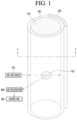
FIG. 1 is a view for explaining a device for measuring turbidity according to an embodiment of the present disclosure. -
FIG. 2 is a cross-sectional view taken along line I-I' ofFIG. 1 . -
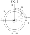
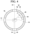
FIGS. 3 to 5 are views for explaining a fluid storage part of the device for measuring the turbidity according to an embodiment of the present disclosure. -
FIG. 6 is a view for explaining a reflector of the device for measuring the turbidity according to an embodiment of the present disclosure. -
FIG. 7 is a view for explaining a method for measuring turbidity in the device for measuring the turbidity according to an embodiment of the present disclosure. -
FIG. 8 is a view for explaining a device for measuring turbidity according to another embodiment of the present disclosure. -
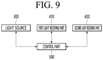
FIG. 9 is a view for explaining a method for measuring turbidity in the device for measuring the turbidity according to another embodiment of the present disclosure. -
FIG. 10 is a view for explaining position setting of the reflector of the device for measuring the turbidity according to an embodiment of the present disclosure. -
FIG. 11 is a view for explaining position setting of a light receiving part of the device for measuring the turbidity according to an embodiment of the present disclosure. -
FIGS. 12 and13 are views for explaining corresponding optical signal amplification before and after the reflector is applied to the device for measuring the turbidity according to an embodiment of the present disclosure. -
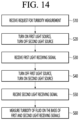
FIG. 14 is a view for explaining a method for measuring turbidity in the device for measuring the turbidity according to an embodiment of the present disclosure. - Hereinafter, embodiments disclosed in this specification is described with reference to the accompanying drawings, and the same or corresponding components are given with the same drawing number regardless of reference number, and their duplicated description will be omitted. The suffixes "module" and "part" for components used in the description below are assigned or mixed in consideration of easiness in writing the specification and do not have distinctive meanings or roles by themselves. Moreover, detailed descriptions related to well-known functions or configurations will be ruled out in order not to unnecessarily obscure subject matters of the present disclosure. However, this does not limit the present disclosure within specific embodiments and it should be understood that the present disclosure covers all the modifications, equivalents, and replacements within the idea and technical scope of the present disclosure.
- It will be understood that although the ordinal numbers such as first and second are used herein to describe various elements, these elements should not be limited by these numbers. The terms are only used to distinguish one component from other components.
- It will also be understood that when an element is referred to as being "'connected to" or "engaged with" another element, it can be directly connected to the other element, or intervening elements can also be present. It will also be understood that when an element is referred to as being 'directly connected to' another element, there is no intervening elements.
-
FIG. 1 is a view for explaining a device for measuring turbidity according to an embodiment of the present disclosure, andFIG. 2 is a cross-sectional view taken along line I-I' ofFIG. 1 . - As illustrated in
FIGS. 1 and2 , a device for measuring turbidity of the present disclosure can include afluid storage part 100 including areflector 200, afirst light source 310 and asecond light source 320, which emit light into afluid 110 inside thefluid storage part 100, alight receiving part 400 that receives scattered light scattered by suspendedparticles 120 of thefluid 110, and acontrol part 500 that controls thefirst light source 310, thesecond light source 320, and thelight receiving part 400 to measure turbidity of thefluid 110. - Here, the
fluid storage part 100 can have a cylindrical shape in which the fluid is stored. - In some cases, the
fluid storage part 100 can have a pipe shape having a through-hole defined therein so that the fluid can flow, but this is only an example and is not limited thereto. - In addition, an entire surface of the
fluid storage part 100 can be provided as a light-transmitting member. - The reason is to allow light emitted from an external light source to be incident into the internal fluid of the
fluid storage part 100 and to receive internal scattered light. - In some cases, only some surfaces of the
fluid storage part 100 can be provided as the light-transmitting member. - For example, the
fluid storage part 100 can have the light-transmitting member only on an incident surface, through which light is incident inward from the outside, and an emission surface, through which the internal scattered light is emitted to the outside. - Here, the
reflector 200 can be attached to an inner surface of thefluid storage part 100. - As another example, the
fluid storage part 100 can have the light-transmitting member only on an incident surface, through which light is incident inward from the outside, an emission surface, through which the internal scattered light is emitted to the outside, and an attachment surface to which thereflector 200 is attached. - Here, the
reflector 200 can be attached to an outer surface of thefluid storage part 100. - The
reflector 200 can amplify the scattered light by reflecting or re-reflecting the scattered light scattered by the suspended particles inside thefluid storage part 100 toward the suspended particles inside thefluid storage part 100. - That is, the
reflector 200 can maximize light reflection characteristics of low turbidity particles with low light scattering. - Here, the
reflector 200 can be disposed between a first surface of thefluid storage part 100 facing thefirst light source 310 and a second surface facing thelight receiving part 400. - The reason is that, when the
reflector 200 is disposed on an area between the first surface facing thefirst light source 310 and the second surface facing thelight receiving part 400 on a surface of thefluid storage part 100, a light receiving signal of thelight receiving part 400, by which a turbidity variation and low turbidity distinction are maximized, can be obtained. - Thus, in the present disclosure, water quality in a low turbidity region can be accurately measured by analyzing the light receiving signal of the
light receiving part 400, by which the turbidity variation and the low turbidity distinction are maximized. - For example, the
reflector 200 can be at least one of a retro-reflective film or a light reflective film, but this is only an example and is not limited thereto. - In addition, the
reflector 200 can amplify the scattered light by reflecting or re-reflecting the scattered light onto the suspendedparticles 120 of thefluid 110. - Here, the
reflector 200 can amplify the scattered light by reflecting or re-reflecting the scattered light toward the suspendedparticles 120 disposed at an inner center of thefluid storage part 100. - For example, a length of the
reflector 200 can be less than or equal to a length of thefluid storage part 100, and a width of thereflector 200 can be less than or equal to a width between the first surface of thefluid storage part 100 facing the firstlight source 310 and the second surface of thefluid storage part 100 facing thelight receiving part 400. - Here, an area of the
reflector 200 can be calculated by a formula expressed by: S = L × W (S is an area of the reflector, L is a length of the fluid storage part, and W is a width between the first surface and the second surface of the fluid storage part), but this is only an example and is not limited thereto. - Next, the first
light source 310 and thelight receiving part 400 can be disposed to be spaced a predetermined angle from each other around thefluid storage part 100 by using thefluid storage part 100 as a center. - For example, the first
light source 310 and thelight receiving part 400 can be disposed in a direction perpendicular to each other by using thefluid storage part 100 as the center. - In addition, the second
light source 320 can be disposed to be spaced a predetermined angle from the firstlight source 310 around thefluid storage part 100 and face thelight receiving part 400. - For example, the second
light source 320 can be perpendicular to the firstlight source 310 with respect to thefluid storage part 100. - In addition, the second
light source 320 and thelight receiving part 400 can be disposed symmetrically at both sides of thefluid storage part 100 along a line passing through a center point of thefluid storage part 100. - In addition, the second
light source 320 can be disposed on a second line having a predetermined angle with respect to the first line while passing through the center point of thefluid storage part 100 when the firstlight source 310 is disposed on the first line passing through the center point of thefluid storage part 100. - For example, the second
light source 320 can be disposed on a second line perpendicular to the first line while passing through the center point of thefluid storage part 100. - In addition, a light output intensity of the second
light source 320 can be the same as a light output intensity of the firstlight source 310. - In some cases, the light output intensity of the second
light source 320 can be different from the light output intensity of the firstlight source 310. - Next, each of the first
light source 310 and the secondlight source 320 can include a light-emitting diode, but this is only one embodiment and is not limited thereto. - Next, the
control part 500 can alternately switch the firstlight source 310 and the secondlight source 320 so that, when the firstlight source 310 is turned on, the secondlight source 320 is turned off, or when the firstlight source 310 is turned off, the secondlight source 320 is turned on. - Here, the
control part 500 can receive a first light receiving signal of thelight receiving part 400 when the firstlight source 310 is turned on, and the secondlight source 320 is turned off, receive a second light receiving signal of thelight receiving part 400 when the firstlight source 310 is turned off, and the secondlight source 320 is turned on, and measure the turbidity of the fluid 110 on the basis of the first light receiving signal and the second light receiving signal. - For example, the first light receiving signal of the
light receiving part 400 can be a light receiving signal generated on the basis of a plurality of scattered light including first scatteredlight 210 in which light emitted from the firstlight source 310 is primarily scattered by the suspendedparticles 120 of the fluid 110, the reflected light 230 in which the firstscattered light 210 is reflected or re-reflected by thereflector 200, and secondscattered light 220 in which the second scattered light is secondarily scattered by the suspendedparticles 120 of thefluid 110. - In addition, the second light receiving signal of the
light receiving part 400 can be a light receiving signal generated on the basis of the firstscattered light 210 in which the light emitted from the secondlight source 320 is primarily scattered by the suspendedparticles 120 of thefluid 110. - In addition, when measuring the turbidity of the fluid 110, if there is no change in the first light receiving signal due to a saturation state of the
light receiving part 400, and the second light receiving signal is normally received, thecontrol part 500 can classify the turbidity of the fluid 110 into a high turbidity region and measure a high turbidity value of the fluid 110 on the basis of the second light receiving signal. - Here, the
control part 500 can measure the turbidity value of the fluid 110 within a range exceeding 1 NTU (Nethelometric Paultity part) and less than 2,000 NTU on the basis of the second light receiving signal when measuring the turbidity value of thefluid 110. - Here, the second light receiving signal can be a light receiving signal generated on the basis of the first
scattered light 210 emitted from the secondlight source 320 and primarily scattered by the suspended particles of thefluid 110. - Next, when measuring the turbidity of the fluid 110, if there is no change in the second light receiving signal due to a saturation state of the
light receiving part 400, and the first light receiving signal is normally received, thecontrol part 500 can classify the turbidity of the fluid 110 into a low turbidity region and measure a low turbidity value of the fluid 110 on the basis of the first light receiving signal. - Here, the
control part 500 can measure the low turbidity value of the fluid 110, which is 1 NTU (Nethelometric Paultity part) or less on the basis of the first light receiving signal when measuring the low turbidity value of thefluid 110. - Here, the first light receiving signal of the
light receiving part 400 can be a light receiving signal generated on the basis of a plurality of scattered light including first scatteredlight 210 in which light emitted from the firstlight source 310 is primarily scattered by the suspendedparticles 120 of the fluid 110, the reflected light 230 in which the firstscattered light 210 is reflected or re-reflected by thereflector 200, and secondscattered light 220 in which the second scattered light is secondarily scattered by the suspendedparticles 120 of thefluid 110. - In addition, the
control part 500 can determine a position of thelight receiving part 400, at which the turbidity variation and the low turbidity distinction are maximized by an equation expressed by: T(x) = a0 + aiP(x, θi) (wherein, T(x) is an output value of a sensor for a sample having a turbidity value of x, a0 is an initial value, ai is a coefficient, and P(x, θi) is a position of the light receiving part having a predetermined angle θ with respect to the fluid storage part having the turbidity value of x). - In addition, the
control part 500 can analyze a pattern of an analog digital converter (ADC) of thereflector 200 at each angle centered on thefluid storage part 100 on the basis of the first light receiving signal of thelight receiving part 400 to determine the position of thereflector 200 at which the turbidity variation and the low turbidity distinction are maximized. - As described above, in the present disclosure, to sense broadband turbidity including the low turbidity and the high turbidity regions, the light source and the
reflector 200 can be fixed, and thelight receiving part 400 can be disposed at a specific position at which the turbidity variation and the low turbidity distinction are maximized, or the light source and thelight receiving part 400 can be fixed, and thereflector 200 can be disposed at a specific position at which the turbidity variation and the low turbidity distinction are maximized. - Thus, in the present disclosure, the optical signal of the low turbidity can be amplified using the reflector to enable the broadband sensing for measuring the water quality from the low turbidity region to the high turbidity region.
- In addition, in the present disclosure, the safety of the drinking water can be secured by sensing the low turbidity of the water quality in the water-containing home appliances using water.
- In addition, in the present disclosure, since the customized filter replacement is enabled according to the water quality pollution level, the unnecessary replacement costs can be reduced by setting the customized filter replacement cycle according to the pollution standard.
- In addition, the present disclosure can be applied to the home appliances such as the water purifiers and the dishwashers that utilize the various water qualities with the broadband sensing function.
- In addition, in the present disclosure, since the light source is implemented using the low-price LED, the low-price sensor can be provided and be expanded to the various home appliances.
- In addition, the present disclosure can provide the water quality control and the customer assurance service through the real-time water quality monitoring and measurement.
-
FIGS. 3 to 5 are views for explaining the fluid storage part of the device for measuring the turbidity according to an embodiment of the present disclosure. - As illustrated in
FIGS. 3 to 5 , thefluid storage part 100 can have a cylindrical shape in which the fluid is stored. - Here, the
fluid storage part 100 can have a pipe shape having a through-hole defined therein so that the fluid can flow, but this is only an example and is not limited thereto. - As illustrated in
FIG. 3 , an entire surface of thefluid storage part 100 can be provided as a light-transmitting member. - The reason is to allow the
first light 312 emitted from the first light source disposed at the outside and thesecond light 322 emitted from the second light source disposed at the outside to be incident into the internal fluid of thefluid storage part 100 so as to receive the internal scattered light into the external light receiving part. - In addition, the
reflector 200 can be disposed between a first surface facing the first light source and a second surface facing the light receiving part on thefluid storage part 100. - Here, the
reflector 200 can amplify the scattered light by reflecting or re-reflecting the scattered light scattered by the suspendedparticles 120 inside thefluid storage part 100 toward the suspendedparticles 120 inside thefluid storage part 100. - For example, in the present disclosure, when the
first light 312 emitted from the first light source disposed at the outside is incident into the internal fluid of thefluid storage part 100, the plurality of scattered light including the firstscattered light 210, in which thefirst light 312 emitted from the first light source is primarily scattered by the suspendedparticles 120 of the fluid, and the secondscattered light 220 in which the reflectedlight 230, in which the firstscattered light 210 is reflected or re-reflected by thereflector 200, is secondarily scattered by suspendedparticles 120 of the fluid 110 can be emitted to the external light receiving part. - In addition, in the present disclosure, when the
second light 322 emitted from the second light source disposed at the outside is incident into the internal fluid of thefluid storage part 100, the firstscattered light 210, in which thesecond light 322 emitted from the second light source is primarily scattered by the suspendedparticles 120 of the fluid, can be emitted to the external light receiving part. - As another embodiment, as illustrated in
FIG. 4 , only some surfaces of thefluid storage part 100 can be provided as a light-transmitting member. - In the
fluid storage part 100, the light-transmittingmember 150 can be disposed only on the incident surface, through which thefirst light 312 and thesecond light 322 are incident inward from the outside, and the emission surface, through which the first and secondscattered light opaque member 160 can be disposed on the remaining area. - Here, the
reflector 200 can be attached to an inner surface of thefluid storage part 100. - As another embodiment, as illustrated in
FIG. 5 , the light-transmittingmember 150 can be disposed only on the incident surface, through which thefirst light 312 and thesecond light 322 are incident inward from the outside, the emission surface, through which the first and secondscattered light reflector 200 is attached, and theopaque member 160 can be disposed on the remaining area. - Here, the
reflector 200 can be attached to an outer surface of thefluid storage part 100. -
FIG. 6 is a view for explaining a reflector of the device for measuring the turbidity according to an embodiment of the present disclosure. - As illustrated in
FIG. 6 , thereflector 200 can amplify the scattered light by reflecting or re-reflecting the scattered light scattered by the suspended particles inside thefluid storage part 100 toward the suspended particles inside thefluid storage part 100. - That is, the
reflector 200 can maximize light reflection characteristics of low turbidity particles with low light scattering. - Here, the
reflector 200 can be disposed between a first surface facing the first light source and a second surface facing the light receiving part on thefluid storage part 100. - The reason is that, when the
reflector 200 is disposed on an area between the first surface facing the first light source and the second surface facing the light receiving part on the surface of thefluid storage part 100, the light receiving signal of the light receiving part, by which the turbidity variation and the low turbidity distinction are maximized, can be obtained. - Thus, in the present disclosure, water quality in a low turbidity region can be accurately measured by analyzing the light receiving signal of the light receiving part, by which the turbidity variation and the low turbidity distinction are maximized.
- The
reflector 200 can be at least one of a retro-reflective film or a light reflective film, but this is only an example and is not limited thereto. - For example, a length L1 of the
reflector 200 can be less than or equal to a length L2 of thefluid storage part 100, and a width W1 of thereflector 200 can be less than or equal to a width W2 between the first surface of thefluid storage part 100 facing the firstlight source 310 and the second surface of thefluid storage part 100 facing the light receiving part. - Here, an area of the
reflector 200 can be calculated by a formula expressed by: S = L × W (S is an area of the reflector, L is a length of the fluid storage part, and W is a width between the first surface and the second surface of the fluid storage part), but this is only an example and is not limited thereto. -
FIG. 7 is a view for explaining a method for measuring turbidity in the device for measuring the turbidity according to an embodiment of the present disclosure. - As illustrated in
FIG. 7 , the present disclosure can include thecontrol part 500 that controls the firstlight source 310, the secondlight source 320, and thelight receiving part 400 to measure the turbidity of the fluid. - Here, the
control part 500 can alternately switch the firstlight source 310 and the secondlight source 320 so that, when the firstlight source 310 is turned on, the secondlight source 320 is turned off, or when the firstlight source 310 is turned off, the secondlight source 320 is turned on. - In addition, the
control part 500 can receive the first light receiving signal of thelight receiving part 400 when the firstlight source 310 is turned on, and the secondlight source 320 is turned off, receive the second light receiving signal of thelight receiving part 400 when the firstlight source 310 is turned off, and the secondlight source 320 is turned on, and measure the turbidity of the fluid on the basis of the first light receiving signal and the second light receiving signal. - For example, the first light receiving signal of the
light receiving part 400 can be a light receiving signal generated on the basis of the plurality of scattered light including first scattered light in which light emitted from the firstlight source 310 is primarily scattered by the suspended particles of the fluid, the reflected light in which the first scattered light is reflected or re-reflected by the reflector, and second scattered light in which the second scattered light is secondarily scattered by the suspended particles of the fluid. - In addition, the second light receiving signal of the
light receiving part 400 can be a light receiving signal generated on the basis of the first scattered light in which the light emitted from the second light source is primarily scattered by the suspended particles of the fluid. - In addition, when measuring the turbidity of the fluid, if there is no change in the first light receiving signal due to a saturation state of the
light receiving part 400, and the second light receiving signal is normally received, thecontrol part 500 can classify the turbidity of the fluid into a high turbidity region and measure a high turbidity value of the fluid on the basis of the second light receiving signal. - Here, the
control part 500 can measure the turbidity value of the fluid within a range exceeding 1 NTU (Nethelometric Paultity part) and less than 2,000 NTU on the basis of the second light receiving signal. - Next, when measuring the turbidity of the fluid, if there is no change in the second light receiving signal due to a saturation state of the
light receiving part 400, and the first light receiving signal is normally received, thecontrol part 500 can classify the turbidity of the fluid into a low turbidity region and measure a low turbidity value of the fluid on the basis of the first light receiving signal. - Here, the
control part 500 can measure the low turbidity value of the fluid 110, which is 1 NTU (Nethelometric Paultity part) or less on the basis of the first light receiving signal. -
FIG. 8 is a view for explaining a device for measuring turbidity according to another embodiment of the present disclosure, andFIG. 9 is a view for explaining a method for measuring turbidity in the device for measuring the turbidity according to another embodiment of the present disclosure. - As illustrated in
FIGS. 8 and9 , a device for measuring turbidity of the present disclosure can include afluid storage part 100 including areflector 200, alight source 300, which emits light into a fluid 110 inside thefluid storage part 100, a firstlight receiving part 410 and a secondlight receiving part 420, which receive scattered light scattered by suspendedparticles 120 of the fluid 110, and acontrol part 500 that controls thelight source 300, the firstlight receiving part 410, and the secondlight receiving part 410 to measure turbidity of thefluid 110. - Here, the
fluid storage part 100 can have a cylindrical shape in which the fluid is stored. - The
reflector 200 can amplify the scattered light by reflecting or re-reflecting the scattered light scattered by the suspended particles inside thefluid storage part 100 toward the suspended particles inside thefluid storage part 100. - That is, the
reflector 200 can maximize light reflection characteristics of low turbidity particles with low light scattering. - Here, the
reflector 200 can be disposed between a first surface facing thelight source 300 and a second surface facing the firstlight receiving part 410 on thefluid storage part 100. - The reason is that, when the
reflector 200 is disposed on an area between the first surface facing thelight source 300 and the second surface facing the firstlight receiving part 410 on the surface of thefluid storage part 100, a light receiving signal of the firstlight receiving part 410, by which a turbidity variation and low turbidity distinction are maximized, can be obtained. - Thus, in the present disclosure, water quality in a low turbidity region can be accurately measured by analyzing the light receiving signal of the first
light receiving part 410, by which the turbidity variation and the low turbidity distinction are maximized. - Next, the
light source 300 and the firstlight receiving part 410 can be disposed to be spaced a predetermined angle from each other around thefluid storage part 100 by using thefluid storage part 100 as a center. - For example, the
light source 300 and the firstlight receiving part 410 can be disposed in a direction perpendicular to each other by using thefluid storage part 100 as the center. - Next, the second
light receiving part 420 can be disposed to be spaced a predetermined angle from the firstlight receiving part 410 around thefluid storage part 100 and face thelight source 300. - For example, the second
light receiving part 420 can be disposed to be perpendicular to the firstlight receiving part 410 and face thelight source 300 by using thefluid storage part 100 as a center. - That is, the
light source 300 and the secondlight receiving part 420 can be disposed symmetrically at both sides of thefluid storage part 100 along a line passing through a center point of thefluid storage part 100. - Here, the second
light receiving part 420 can be disposed on a second line having a predetermined angle with respect to the first line while passing through the center point of thefluid storage part 100 when the firstlight receiving part 410 is disposed on the first line passing through the center point of thefluid storage part 100. - For example, the second
light receiving part 420 can be disposed on a second line perpendicular to the first line while passing through the center point of thefluid storage part 100. - Each of the first
light receiving part 410 and the secondlight receiving part 420 of the present disclosure can be a photodiode, but this is only an example and is not limited thereto. - In addition, as illustrated in
FIG. 9 , thecontrol part 500 of the present disclosure can alternatively switch the firstlight receiving part 410 and the secondlight receiving part 420 so that, when thelight source 300 and the firstlight receiving part 410 are turned on, the secondlight receiving part 420 is turned off, or when thelight source 300 is turned on, and the firstlight receiving part 410 is turned off, the secondlight receiving part 420 is turned on. - Here, the
control part 500 can receive a first light receiving signal of the firstlight receiving part 410 when the firstlight receiving part 410 is turned on, and the secondlight receiving part 420 is turned off, and receive a second light receiving signal of the secondlight receiving part 420 when the firstlight receiving part 410 is turned off, and the secondlight receiving part 420 is turned on, and measure the turbidity of the fluid 110 on the basis of the first light receiving signal and the second light receiving signal. - For example, the first light receiving signal of the first
light receiving part 410 can be a light receiving signal generated on the basis of a plurality of scattered light including first scatteredlight 210 in which light emitted from thelight source 300 is primarily scattered by the suspendedparticles 120 of the fluid 110, the reflected light 230 in which the firstscattered light 210 is reflected or re-reflected by thereflector 200, and secondscattered light 220 in which the second scattered light is secondarily scattered by the suspendedparticles 120 of thefluid 110. - In addition, the second light receiving signal of the second
light receiving part 420 can be a light receiving signal generated on the basis of the firstscattered light 210 in which the light emitted from thelight source 300 is primarily scattered by the suspendedparticles 120 of thefluid 110. - In addition, when measuring the turbidity of the fluid 110, if there is no change in the first light receiving signal due to a saturation state of the first
light receiving part 410, and the second light receiving signal of the secondlight receiving part 420 is normally received, thecontrol part 500 can classify the turbidity of the fluid 110 into a high turbidity region and measure a high turbidity value of the fluid 110 on the basis of the second light receiving signal. - Here, the
control part 500 can measure the turbidity value of the fluid 110 within a range exceeding 1 NTU (Nethelometric Paultity part) and less than 2,000 NTU on the basis of the second light receiving signal of the secondlight receiving part 420 when measuring the turbidity value of thefluid 110. - At this time, the second light receiving signal of the second
light receiving part 420 can be a light receiving signal generated on the basis of the firstscattered light 210 emitted from the secondlight source 300 and primarily scattered by the suspended particles of thefluid 110. - Next, when measuring the turbidity of the fluid 110, if there is no change in the second light receiving signal due to a saturation state of the second
light receiving part 420, and the first light receiving signal of the firstlight receiving part 410 is normally received, thecontrol part 500 can classify the turbidity of the fluid 110 into a low turbidity region and measure a low turbidity value of the fluid 110 on the basis of the first light receiving signal. - Here, the
control part 500 can measure the low turbidity value of the fluid 110, which is 1 NTU (Nethelometric Paultity part) or less on the basis of the first light receiving signal of the firstlight receiving part 410 when measuring the low turbidity value of thefluid 110. - Here, the first light receiving signal of the first
light receiving part 410 can be a light receiving signal generated on the basis of a plurality of scattered light including first scatteredlight 210 in which light emitted from thelight source 300 is primarily scattered by the suspendedparticles 120 of the fluid 110, the reflected light 230 in which the firstscattered light 210 is reflected or re-reflected by thereflector 200, and secondscattered light 220 in which the second scattered light is secondarily scattered by the suspendedparticles 120 of thefluid 110. -
FIG. 10 is a view for explaining position setting of the reflector of the device for measuring the turbidity according to an embodiment of the present disclosure. - As illustrated in
FIG. 10 , in the present disclosure, a pattern of an analog digital converter (ADC) of thereflector 200 at each angle centered on the fluid storage part on the basis of the first light receiving signal of the light receiving part can be analyzed to determine a position of thereflector 200 at which the turbidity variation and the low turbidity distinction are maximized. - For example, in the present disclosure, when determining the position of the
reflector 200, as illustrated inFIG. 10 , a specific position at which the intensity of the light receiving signal pattern is amplified, and also, a turbidity value of 1.1 NTU of a high turbidity pattern A and a turbidity value of 0.1 NTU of a low turbidity pattern B are distinguished from each other, can be determined as the position of thereflector 200. - That is, in the present disclosure, the positions of the light source and the light receiver can be fixed, and the position of the
reflector 200 can vary to fine a specific position at which the turbidity variation and the low turbidity distinction are maximized. - Thus, in the present disclosure, the optical signal of the low turbidity can be amplified using the
reflector 200 to enable the broadband sensing for measuring the water quality from the low turbidity region to the high turbidity region. -
FIG. 11 is a view for explaining position setting of a light receiving part of the device for measuring the turbidity according to an embodiment of the present disclosure. - As illustrated in
FIG. 11 , in the present disclosure, a position of thelight receiving part 400, at which the turbidity variation and the low turbidity distinction are maximized by an equation expressed by: T(x) = a0 + aiP(x, θi) (wherein, T(x) is an output value of a sensor for a sample having a turbidity value of x, a0 is an initial value, ai is a coefficient, and P(x, θi) is a position of the light receiving part having a predetermined angle θ with respect to the fluid storage part having the turbidity value of x), can be determined. - For example, in the present disclosure, when determining the position of the light receiving part that is a photodiode, as illustrated in
FIG. 11 , a specific position at which the signal intensities of the high-turbidity light receiving signal pattern and the low-turbidity light receiving signal pattern are amplified, and the low turbidity is distinguished, can be determined as the position of the light receiving part on the basis of the light receiving signal pattern for each turbidity. - That is, in the present disclosure, the positions of the light source and the reflector can be fixed, and the position of the light receiving part can vary to find a specific position at which the turbidity variation and the low turbidity distinction are maximized.
-
FIGS. 12 and13 are views for explaining corresponding optical signal amplification before and after the reflector is applied to the device for measuring the turbidity according to an embodiment of the present disclosure. -
FIG. 12 is a view for explaining corresponding optical signal amplification before the reflector of the present disclosure is applied, andFIG. 13 is a view for explaining corresponding optical signal amplification after the reflector of the present disclosure is applied. - As illustrated in
FIG. 12 , if the reflector is not applied, when the ACDC value of the light receiving signal is measured according to turbidity of a solution sample, since a turbidity inclination showing the light amplification appears to be approximately 126.8, it is difficult to distinguish a low turbidity signal value and a high turbidity signal value from each other, and thus low turbidity measurement is impossible. - In contrast, as illustrated in
FIG. 13 , if the reflector is applied, when the ACDC value of the light receiving signal is measured according to the turbidity of the solution sample, since the turbidity inclination showing the light amplification is improved to approximately 311.2, the low turbidity signal value and the high turbidity signal value can be distinguished from each other, and thus the low turbidity measurement is possible. -
FIG. 14 is a view for explaining a method for measuring turbidity in the device for measuring the turbidity according to an embodiment of the present disclosure. - As illustrated in
FIG. 14 , in the present disclosure, a user input requesting turbidity measurement can be received (S10). - In addition, in the present disclosure, when the user input is received, a first light source can be turned on, and a second light source can be turned off (S20).
- Next, in the present disclosure, a first light receiving signal can be received from a light receiving part (S30).
- Here, the first light receiving signal of the light receiving part can be a light receiving signal generated on the basis of a plurality of scattered light including first scattered light in which light emitted from the first light source is primarily scattered by suspended particles of a fluid, reflected light in which the first scattered light is reflected or re-reflected by the reflector, and second scattered light in which second scattered light is secondarily scattered by the suspended particles of the fluid.
- Next, in the present disclosure, the first light source can be turned off, and the second light source can be turned on (S40).
- In addition, in the present disclosure, a second light receiving signal can be received from the light receiving part (S50).
- Here, the second light receiving signal can be a light receiving signal generated on the basis of the first scattered light in which the light emitted from the second light source is primarily scattered by the suspended particles of the fluid.
- Next, in the present disclosure, turbidity of the fluid can be measured on the basis of the first light receiving signal and the second light receiving signal (S60).
- Here, in the present disclosure, when the turbidity of the fluid is measured, the control part can be configured to classify the turbidity of the fluid into a high turbidity region to measure a high turbidity value of the fluid on the basis of the second light receiving signal when there is no change in the first light receiving signal due to a saturation state of the light receiving part, and the second light receiving signal is normally received.
- In addition, in the present disclosure, when the turbidity of the fluid is measured, the control part can be configured to classify the turbidity of the fluid into a low turbidity region to measure a low turbidity value of the fluid on the basis of the first light receiving signal when there is no change in the second light receiving signal due to the saturation state of the light receiving part, and the second light receiving signal is normally received.
- As described above, the device for measuring the turbidity according to the present disclosure can amplify the optical signal of the low turbidity using the reflector to enable the broadband sensing for measuring the water quality from the low turbidity region to the high turbidity region.
- In addition, in the present disclosure, the safety of the drinking water can be secured by sensing the low turbidity of the water quality in the water-containing home appliances using water.
- In addition, in the present disclosure, since the customized filter replacement is enabled according to the water quality pollution level, the unnecessary replacement costs can be reduced by setting the customized filter replacement cycle according to the pollution standard.
- In addition, the present disclosure can be applied to the home appliances such as the water purifiers and the dishwashers that utilize the various water qualities with the broadband sensing function.
- In addition, in the present disclosure, since the light source is implemented using the low-price LED, the low-price sensor can be provided and be expanded to the various home appliances.
- In addition, the present disclosure can provide the water quality control and the customer assurance service through the real-time water quality monitoring and measurement.
- According to the device for measuring the turbidity according to the present disclosure, the low turbidity optical signal can be by amplified using the reflector to enable the broadband sensing for measuring the water quality from the low turbidity region to the high turbidity region, and therefore, the industrial applicability is remarkable.
Claims (15)
- A device for measuring turbidity, comprising:a fluid storage part comprising a reflector;a first light source configured to emit light to a fluid within the fluid storage part;a first light receiving part configured to receive scattered light scattered by suspended particles in the fluid; anda control part configured to measure turbidity of the fluid by controlling the first light source and the first light receiving part,wherein the first light source and the first light receiving part are disposed to be spaced a predetermined angle from each other around the fluid storage part in the vicinity of the fluid storage part, andthe reflector is disposed between a first surface facing the first light source and a second surface facing the first light receiving part on a surface of the fluid storage part.
- The device according to claim 1, wherein the reflector is configured to reflect or re-reflect the scattered light onto the suspended particles of the fluid, thereby amplifying the scattered light.
- The device according to claim 1, further comprising a second light source configured to emit light to the fluid within the fluid storage part,
wherein the second light source is spaced a predetermined angle from the first light source around the fluid storage part and disposed to face the first light receiving part. - The device according to claim 3, wherein each of the first light source and the second light source comprises a light emitting diode.
- The device according to claim 3, wherein the control part is configured to:turn off the second light source when the first light source is turned on; oralternately switch the first light source and the second light source so that the second light source is turned on when the first light source is turned off.
- The device according to claim 5, wherein the control part is configured to:receive a first light receiving signal of the first light receiving part when the first light source is turned on, and the second light source is turned off;receive a second light receiving signal of the first light receiving part when the first light source is turned off, and the second light source is turned on; andmeasure the turbidity of the fluid on the basis of the first light receiving signal and the second light receiving signal.
- The device according to claim 6, wherein the first light receiving signal of the first light receiving part is a light receiving signal on the basis of a plurality of scattered light comprising first scattered light, in which light emitted from the first light source is primarily scattered by the suspended particles of the fluid, and second scattered light, in which the first scattered light is reflected or re-reflected by the reflector and is secondarily scattered by the suspended particles of the fluid, and
the second light receiving signal of the first light receiving part is a light receiving signal generated on the basis of the first scattered light, in which light emitted from the second light source is primarily scattered by the suspended particles of the fluid. - The device according to claim 6, wherein, when the turbidity of the fluid is measured, the control part is configured to classify the turbidity of the fluid into a high turbidity region to measure a high turbidity value of the fluid on the basis of the second light receiving signal when there is no change in the first light receiving signal due to a saturation state of the first light receiving part, and the second light receiving signal is normally received.
- The device according to claim 6, wherein, when the turbidity of the fluid is measured, the control part is configured to classify the turbidity of the fluid into a low turbidity region to measure a low turbidity value of the fluid on the basis of the first light receiving signal when there is no change in the second light receiving signal due to a saturation state of the first light receiving part, and the second light receiving signal is normally received.
- The device according to claim 1, further comprising a second light receiving part configured to receive the scattered light scattered by the suspended particles of the fluid,
wherein the second light receiving part is spaced a predetermined angle from the first light receiving part around the fluid storage part and disposed to face the first light receiving part. - The device according to claim 10, wherein each of the first light receiving part and the second light receiving part comprises a photodiode.
- The device according to claim 10, wherein the control part is configured to:turn off the second light receiving part when the first light source and the first light receiving part are turned on; oralternatively switch the first light receiving part and the second light receiving part so that the second light receiving part is turned on when the first light source is turned on, and the first light receiving part is turned off.
- The device according to claim 12, wherein, when the turbidity of the fluid is measured, the control part is configured to classify the turbidity of the fluid into a high turbidity region to measure a high turbidity value of the fluid on the basis of the second light receiving signal when there is no change in the first light receiving signal due to a saturation state of the first light receiving part, and the second light receiving signal of the second light receiving part is normally received.
- The device according to claim 12, wherein, when the turbidity of the fluid is measured, the control part is configured to classify the turbidity of the fluid into a low turbidity region to measure a low turbidity value of the fluid on the basis of the first light receiving signal when there is no change in the second light receiving signal due to a saturation state of the second light receiving part, and the second light receiving signal of the first light receiving part is normally received.
- A method for measuring turbidity using a device for measuring turbidity, which comprises a first light source, a second light source, and a light receiving part, which are disposed at predetermined angles around a fluid storage part comprising a reflector, the method comprising:receiving an user input requesting a turbidity measurement;turning on the first light source and turning off the second light source when the user input is received;receiving a first light receiving signal from the light receiving part:turning off the first light source and turning on the second light source;receiving a second light receiving signal from the light receiving part: andmeasuring the turbidity of the fluid on the basis of the first light receiving signal and the second light receiving signal.
Applications Claiming Priority (2)
| Application Number | Priority Date | Filing Date | Title |
|---|---|---|---|
| KR1020220137662A KR102756884B1 (en) | 2022-10-24 | 2022-10-24 | Apparatus and method for measuring turbidity |
| PCT/KR2022/017871 WO2024090647A1 (en) | 2022-10-24 | 2022-11-14 | Device and method for measuring turbidity |
Publications (2)
| Publication Number | Publication Date |
|---|---|
| EP4582788A1 true EP4582788A1 (en) | 2025-07-09 |
| EP4582788A4 EP4582788A4 (en) | 2025-11-19 |
Family
ID=90831084
Family Applications (1)
| Application Number | Title | Priority Date | Filing Date |
|---|---|---|---|
| EP22963608.9A Pending EP4582788A4 (en) | 2022-10-24 | 2022-11-14 | DEVICE AND METHOD FOR VIOLENCE MEASUREMENT |
Country Status (5)
| Country | Link |
|---|---|
| US (1) | US20260126384A1 (en) |
| EP (1) | EP4582788A4 (en) |
| KR (2) | KR102756884B1 (en) |
| CN (1) | CN120077259A (en) |
| WO (1) | WO2024090647A1 (en) |
Families Citing this family (2)
| Publication number | Priority date | Publication date | Assignee | Title |
|---|---|---|---|---|
| DE102023133015A1 (en) * | 2023-11-27 | 2025-05-28 | Endress+Hauser Conducta Gmbh+Co. Kg | Method for determining a scattered light parameter and measuring arrangement for carrying out the method |
| KR102976770B1 (en) * | 2026-04-30 | 2026-06-12 | 주식회사 아키테크 | Apparatus and method for discriminating underwater substances for water quality monitoring |
Family Cites Families (18)
| Publication number | Priority date | Publication date | Assignee | Title |
|---|---|---|---|---|
| JPS639838A (en) * | 1986-06-30 | 1988-01-16 | Shimizu Constr Co Ltd | Particulate detection device |
| US5828458A (en) * | 1995-01-26 | 1998-10-27 | Nartron Corporation | Turbidity sensor |
| JP2000074831A (en) * | 1998-08-26 | 2000-03-14 | Matsushita Electric Works Ltd | Turbidity meter |
| JP2002131214A (en) | 2000-10-26 | 2002-05-09 | Rion Co Ltd | Laser oscillator and light scattering particle detector using it |
| JP2002223019A (en) | 2001-01-24 | 2002-08-09 | Rion Co Ltd | Laser oscillator and light scattering particle detector using it |
| US6836332B2 (en) * | 2001-09-25 | 2004-12-28 | Tennessee Scientific, Inc. | Instrument and method for testing fluid characteristics |
| US6813050B2 (en) * | 2002-01-18 | 2004-11-02 | Nanguang Chen | Rotary mirror array for fast optical tomography |
| JP2007199012A (en) | 2006-01-30 | 2007-08-09 | Nidec Sankyo Corp | Apparatus for counting light scattered particle |
| KR101132406B1 (en) | 2009-09-30 | 2012-04-03 | 김태성 | Optical Scattering Type Paticle Measurement Apparatus |
| JP2013088302A (en) * | 2011-10-19 | 2013-05-13 | Dkk Toa Corp | Detector and water quality measuring instrument |
| JP6275440B2 (en) | 2013-01-21 | 2018-02-07 | 株式会社 堀場アドバンスドテクノ | Turbidimeter |
| JP6246376B2 (en) * | 2013-09-30 | 2017-12-13 | ハッハ ランゲ ゲゼルシャフト ミット ベシュレンクテル ハフツングHach Lange Gmbh | Nephelometric turbidimeter and method for detection of contamination of a nephelometric turbidimeter sample cuvette |
| KR20150111538A (en) * | 2014-03-25 | 2015-10-06 | 주식회사 대유위니아 | Measuring apparatus for pollution level in humidifier and method thereof |
| KR101825161B1 (en) * | 2016-04-26 | 2018-02-06 | (주)미디어에버 | Detection apparatus for micro dust and organism |
| WO2017199511A1 (en) * | 2016-05-19 | 2017-11-23 | 富士電機株式会社 | Water quality analyzer |
| SE540009C2 (en) | 2016-06-03 | 2018-02-20 | Braennstroem Gruppen Ab | Method and apparatus for determining a concentration of a substance in a liquid medium |
| KR102596982B1 (en) * | 2018-12-24 | 2023-11-02 | 삼성전자주식회사 | Washing apparatus and controlling method thereof |
| KR102543670B1 (en) * | 2020-11-30 | 2023-06-16 | 주식회사 더웨이브톡 | Turbidity Meter |
-
2022
- 2022-10-24 KR KR1020220137662A patent/KR102756884B1/en active Active
- 2022-11-14 EP EP22963608.9A patent/EP4582788A4/en active Pending
- 2022-11-14 CN CN202280101107.8A patent/CN120077259A/en active Pending
- 2022-11-14 US US19/119,959 patent/US20260126384A1/en active Pending
- 2022-11-14 WO PCT/KR2022/017871 patent/WO2024090647A1/en not_active Ceased
-
2024
- 2024-12-18 KR KR1020240190406A patent/KR20250002073A/en active Pending
Also Published As
| Publication number | Publication date |
|---|---|
| KR20250002073A (en) | 2025-01-07 |
| CN120077259A (en) | 2025-05-30 |
| WO2024090647A1 (en) | 2024-05-02 |
| EP4582788A4 (en) | 2025-11-19 |
| KR102756884B1 (en) | 2025-01-21 |
| US20260126384A1 (en) | 2026-05-07 |
| KR20240057200A (en) | 2024-05-02 |
Similar Documents
| Publication | Publication Date | Title |
|---|---|---|
| US20260126384A1 (en) | Device and method for measuring turbidity | |
| US4925299A (en) | Hemoglobin detector | |
| JP4381370B2 (en) | Turbidity sensor | |
| US4803470A (en) | Substance detector device | |
| US20080105837A1 (en) | Sensor for detecting contaminants and/or rain and method for operating a sensor | |
| CN105954160B (en) | Fine dust measuring method and fine dust sensor for determining particle size of fine dust | |
| JP2006500560A (en) | Chemochromic sensor, chemochromic reagent and test material detection method | |
| JPH07325049A (en) | Foreign material detection device | |
| JP2013504038A (en) | Optical scanning apparatus and method for moving fiber material | |
| CN110672523A (en) | Turbidity sensor | |
| KR20170115248A (en) | Rain sensor with multi-sensitivity | |
| US6373215B1 (en) | Device for monitoring the state of a window pane | |
| WO1995024635A1 (en) | Method and apparatus for detecting impurities on plate surface | |
| US20140291548A1 (en) | Fluorescence gas and liquid sensor | |
| CN216013383U (en) | Blood coagulation analysis and detection system and blood coagulation instrument | |
| US20030038950A1 (en) | Apparatus for handling liquids and a process for operating the device | |
| CN114729885A (en) | Optical-based particulate matter sensing | |
| KR20230123523A (en) | Liquid type discrimination sensor | |
| CN102809536A (en) | Reaction cup chain and biochemistry analyzer using the same | |
| JP2017146226A (en) | Automatic analyzer | |
| JP2008537591A (en) | Apparatus and method for optical scanning of an elongated fiber material | |
| EP1275015A2 (en) | Multifunction optical sensor with variable detection threshold and noise suppression | |
| KR20240096254A (en) | Turbidity sensor and control method thereof | |
| JP4615343B2 (en) | Coin identification device | |
| EP0825432A2 (en) | Light emitting diode and optical apparatus |
Legal Events
| Date | Code | Title | Description |
|---|---|---|---|
| STAA | Information on the status of an ep patent application or granted ep patent |
Free format text: STATUS: THE INTERNATIONAL PUBLICATION HAS BEEN MADE |
|
| PUAI | Public reference made under article 153(3) epc to a published international application that has entered the european phase |
Free format text: ORIGINAL CODE: 0009012 |
|
| STAA | Information on the status of an ep patent application or granted ep patent |
Free format text: STATUS: REQUEST FOR EXAMINATION WAS MADE |
|
| 17P | Request for examination filed |
Effective date: 20250330 |
|
| AK | Designated contracting states |
Kind code of ref document: A1 Designated state(s): AL AT BE BG CH CY CZ DE DK EE ES FI FR GB GR HR HU IE IS IT LI LT LU LV MC ME MK MT NL NO PL PT RO RS SE SI SK SM TR |
|
| A4 | Supplementary search report drawn up and despatched |
Effective date: 20251016 |
|
| RIC1 | Information provided on ipc code assigned before grant |
Ipc: G01N 15/06 20240101AFI20251010BHEP Ipc: G01N 21/49 20060101ALI20251010BHEP Ipc: G01N 33/18 20060101ALI20251010BHEP Ipc: G01N 15/075 20240101ALI20251010BHEP Ipc: G01N 21/51 20060101ALI20251010BHEP Ipc: G01N 21/53 20060101ALN20251010BHEP |
|
| DAV | Request for validation of the european patent (deleted) | ||
| DAX | Request for extension of the european patent (deleted) |