EP4582748A1 - Air purification device and air conditioner - Google Patents
Air purification device and air conditioner Download PDFInfo
- Publication number
- EP4582748A1 EP4582748A1 EP23858643.2A EP23858643A EP4582748A1 EP 4582748 A1 EP4582748 A1 EP 4582748A1 EP 23858643 A EP23858643 A EP 23858643A EP 4582748 A1 EP4582748 A1 EP 4582748A1
- Authority
- EP
- European Patent Office
- Prior art keywords
- electrode
- purification device
- base
- air purification
- protective cover
- Prior art date
- Legal status (The legal status is an assumption and is not a legal conclusion. Google has not performed a legal analysis and makes no representation as to the accuracy of the status listed.)
- Pending
Links
Images


Classifications
-
- A—HUMAN NECESSITIES
- A61—MEDICAL OR VETERINARY SCIENCE; HYGIENE
- A61L—METHODS OR APPARATUS FOR STERILISING MATERIALS OR OBJECTS IN GENERAL; DISINFECTION, STERILISATION OR DEODORISATION OF AIR; CHEMICAL ASPECTS OF BANDAGES, DRESSINGS, ABSORBENT PADS OR SURGICAL ARTICLES; MATERIALS FOR BANDAGES, DRESSINGS, ABSORBENT PADS OR SURGICAL ARTICLES
- A61L9/00—Disinfection, sterilisation or deodorisation of air
- A61L9/16—Disinfection, sterilisation or deodorisation of air using physical phenomena
- A61L9/22—Ionisation
-
- F—MECHANICAL ENGINEERING; LIGHTING; HEATING; WEAPONS; BLASTING
- F24—HEATING; RANGES; VENTILATING
- F24F—AIR-CONDITIONING; AIR-HUMIDIFICATION; VENTILATION; USE OF AIR CURRENTS FOR SCREENING
- F24F1/00—Room units for air-conditioning, e.g. separate or self-contained units or units receiving primary air from a central station
- F24F1/0007—Indoor units, e.g. fan coil units
- F24F1/0071—Indoor units, e.g. fan coil units with means for purifying supplied air
-
- F—MECHANICAL ENGINEERING; LIGHTING; HEATING; WEAPONS; BLASTING
- F24—HEATING; RANGES; VENTILATING
- F24F—AIR-CONDITIONING; AIR-HUMIDIFICATION; VENTILATION; USE OF AIR CURRENTS FOR SCREENING
- F24F8/00—Treatment, e.g. purification, of air supplied to human living or working spaces otherwise than by heating, cooling, humidifying or drying
- F24F8/10—Treatment, e.g. purification, of air supplied to human living or working spaces otherwise than by heating, cooling, humidifying or drying by separation, e.g. by filtering
- F24F8/192—Treatment, e.g. purification, of air supplied to human living or working spaces otherwise than by heating, cooling, humidifying or drying by separation, e.g. by filtering by electrical means, e.g. by applying electrostatic fields or high voltages
-
- F—MECHANICAL ENGINEERING; LIGHTING; HEATING; WEAPONS; BLASTING
- F24—HEATING; RANGES; VENTILATING
- F24F—AIR-CONDITIONING; AIR-HUMIDIFICATION; VENTILATION; USE OF AIR CURRENTS FOR SCREENING
- F24F8/00—Treatment, e.g. purification, of air supplied to human living or working spaces otherwise than by heating, cooling, humidifying or drying
- F24F8/20—Treatment, e.g. purification, of air supplied to human living or working spaces otherwise than by heating, cooling, humidifying or drying by sterilisation
-
- F—MECHANICAL ENGINEERING; LIGHTING; HEATING; WEAPONS; BLASTING
- F24—HEATING; RANGES; VENTILATING
- F24F—AIR-CONDITIONING; AIR-HUMIDIFICATION; VENTILATION; USE OF AIR CURRENTS FOR SCREENING
- F24F8/00—Treatment, e.g. purification, of air supplied to human living or working spaces otherwise than by heating, cooling, humidifying or drying
- F24F8/30—Treatment, e.g. purification, of air supplied to human living or working spaces otherwise than by heating, cooling, humidifying or drying by ionisation
-
- H—ELECTRICITY
- H05—ELECTRIC TECHNIQUES NOT OTHERWISE PROVIDED FOR
- H05H—PLASMA TECHNIQUE; PRODUCTION OF ACCELERATED ELECTRICALLY-CHARGED PARTICLES OR OF NEUTRONS; PRODUCTION OR ACCELERATION OF NEUTRAL MOLECULAR OR ATOMIC BEAMS
- H05H1/00—Generating plasma; Handling plasma
- H05H1/24—Generating plasma
- H05H1/47—Generating plasma using corona discharges
- H05H1/471—Pointed electrodes
-
- A—HUMAN NECESSITIES
- A61—MEDICAL OR VETERINARY SCIENCE; HYGIENE
- A61L—METHODS OR APPARATUS FOR STERILISING MATERIALS OR OBJECTS IN GENERAL; DISINFECTION, STERILISATION OR DEODORISATION OF AIR; CHEMICAL ASPECTS OF BANDAGES, DRESSINGS, ABSORBENT PADS OR SURGICAL ARTICLES; MATERIALS FOR BANDAGES, DRESSINGS, ABSORBENT PADS OR SURGICAL ARTICLES
- A61L2209/00—Aspects relating to disinfection, sterilisation or deodorisation of air
- A61L2209/10—Apparatus features
- A61L2209/16—Connections to a HVAC unit
-
- F—MECHANICAL ENGINEERING; LIGHTING; HEATING; WEAPONS; BLASTING
- F24—HEATING; RANGES; VENTILATING
- F24F—AIR-CONDITIONING; AIR-HUMIDIFICATION; VENTILATION; USE OF AIR CURRENTS FOR SCREENING
- F24F2130/00—Control inputs relating to environmental factors not covered by group F24F2110/00
-
- F—MECHANICAL ENGINEERING; LIGHTING; HEATING; WEAPONS; BLASTING
- F24—HEATING; RANGES; VENTILATING
- F24F—AIR-CONDITIONING; AIR-HUMIDIFICATION; VENTILATION; USE OF AIR CURRENTS FOR SCREENING
- F24F2130/00—Control inputs relating to environmental factors not covered by group F24F2110/00
- F24F2130/20—Sunlight
-
- H—ELECTRICITY
- H05—ELECTRIC TECHNIQUES NOT OTHERWISE PROVIDED FOR
- H05H—PLASMA TECHNIQUE; PRODUCTION OF ACCELERATED ELECTRICALLY-CHARGED PARTICLES OR OF NEUTRONS; PRODUCTION OR ACCELERATION OF NEUTRAL MOLECULAR OR ATOMIC BEAMS
- H05H2245/00—Applications of plasma devices
- H05H2245/10—Treatment of gases
- H05H2245/15—Ambient air; Ozonisers
Definitions
- the present disclosure relates to the field of air-conditioning equipment, and in particular, to an air purification device and an air conditioner.
- the air purification device according to the embodiments of the present disclosure at least has the following beneficial effects.
- the ion generation assembly uses the high-voltage discharge of the at least one first electrode to generate negative ions, and the second electrode and the third electrode are respectively arranged on the base and the protective cover, such that the second electrode and the third electrode are spaced apart to form a strong electric field, to generate plasmas.
- the generated negative ions and plasmas can diffuse into the air through the hollowed-out structure to sterilize the air, can kill bacteria and viruses in the air entering the protective cover, and also provides a certain odor removal effect.
- the air purification device of the present disclosure has the advantages of purification using negative ions and purification using plasmas and effectively improves the purification effect.
- the protective cover can effectively protect the electrodes therein, and can also prevent a human body from accessing the electrodes in the protective cover, thereby improving the usage safety.
- the at least one first electrode and the second electrode are electrically connected, and are connected to a high-voltage electrode of a power supply through a first conductive member, and the third electrode is connected to a ground electrode of the power supply through a second conductive member.
- the at least one first electrode and the second electrode are fixedly connected to form a unity or are connected by a wire.
- the at least one first electrode and the second electrode extend into the base, and the first conductive member is connected to the at least one first electrode or the second electrode in the base and extends out from the base to connect to the high-voltage electrode of the power supply.
- the second conductive member is connected to the third electrode in the protective cover and extends toward the base, and the second conductive member extends into the base and extends out from the base to connect to the ground electrode of the power supply.
- the second electrode comprises an electrode plate.
- the electrode plate comprises a plurality of second tip portions arranged in a length direction of the electrode plate, and the at least one first electrode is connected to an end of the electrode plate.
- At least two first electrodes are provided, and the at least two first electrodes are divided into two groups and respectively arranged at two ends of the electrode plate, or the at least two first electrodes are both arranged at one end of the electrode plate.
- the second tip portion is of a tooth-like, needle-tip, or filament-like structure.
- a connecting rib is arranged on a side wall of the protective cover away from the base, the third electrode is arranged on a side of the connecting rib facing the base, and the connecting rib, the second electrode, and the third electrode respectively extend in a length direction of the base.
- a length by which the third electrode extends in the length direction of the base is less than or equal to a length of the connecting rib, and a width of the third electrode is less than or equal to a width of the connecting rib.
- shielding portions are arranged on the side wall of the protective cover away from the base, the shielding portions are respectively located at two ends of the connecting rib.
- Connecting portions are respectively arranged at two ends of the third electrode, and the connecting portions are connected to a side of the shielding portions facing the base.
- a length of the third electrode is greater than a length of a discharge portion of the second electrode.
- the third electrode and the second electrode are staggered in a height direction of the base.
- the protective cover comprises a frame and a plurality of grid bars connected to the frame.
- the plurality of grid bars are arranged at an interval in a length direction of the base to form a grille arrangement to construct the hollowed-out structure.
- a spacing is formed between adjacent grid bars.
- a discharge portion of the at least one first electrode and/or the discharge portion of the second electrode is exposed through the spacing in the width direction of the base.
- the spacing between adjacent grid bars is less than or equal to 6 mm.
- the first tip portion comprises a plurality of conductive fibers connected to the basal portion.
Landscapes
- Engineering & Computer Science (AREA)
- Plasma & Fusion (AREA)
- Physics & Mathematics (AREA)
- General Engineering & Computer Science (AREA)
- Chemical & Material Sciences (AREA)
- Combustion & Propulsion (AREA)
- Mechanical Engineering (AREA)
- Health & Medical Sciences (AREA)
- Spectroscopy & Molecular Physics (AREA)
- Epidemiology (AREA)
- Life Sciences & Earth Sciences (AREA)
- Animal Behavior & Ethology (AREA)
- General Health & Medical Sciences (AREA)
- Public Health (AREA)
- Veterinary Medicine (AREA)
- Disinfection, Sterilisation Or Deodorisation Of Air (AREA)
Abstract
Description
- This application claims priority to
Chinese Patent Application No. 202211065958.X filed August 31, 2022 Chinese Patent Application No. 202222329915.X filed August 31, 2022 - The present disclosure relates to the field of air-conditioning equipment, and in particular, to an air purification device and an air conditioner.
- Both negative ion generators and plasma generators have a function of purifying air, and each has its own advantages. In the related art, a negative ion generator and a plasma generator are combined together for purification, but the structural design is unreasonable and thus it is difficult to balance the functions of negative ions and plasma, resulting in ineffective purification.
- The present disclosure aims to at least partially resolve one of the problems in the related art. To this end, the present disclosure provides an air purification device, which can generate negative ions and plasmas to purify air. The structural design is more reasonable with higher compatibility, and effectively improves the purification effect.
- In accordance with a first aspect of the present disclosure, an embodiment provides an air purification device, comprising: a housing, comprising a protective cover and a base connected to the protective cover;
- an ion generation assembly, comprising at least one first electrode, a second electrode, and a third electrode, where the at least one first electrode is configured for discharging to generate negative ions, and the second electrode is spaced apart from the third electrode and is configured for cooperating with the third electrode to generate plasmas;
- where the protective cover is of a hollowed-out structure, the hollowed-out structure covers the ion generation assembly, the at least one first electrode and the second electrode are fixedly connected to the base, and the third electrode is fixedly connected to an inner side of the protective cover.
- The air purification device according to the embodiments of the present disclosure at least has the following beneficial effects.
- The ion generation assembly uses the high-voltage discharge of the at least one first electrode to generate negative ions, and the second electrode and the third electrode are respectively arranged on the base and the protective cover, such that the second electrode and the third electrode are spaced apart to form a strong electric field, to generate plasmas. The generated negative ions and plasmas can diffuse into the air through the hollowed-out structure to sterilize the air, can kill bacteria and viruses in the air entering the protective cover, and also provides a certain odor removal effect. The air purification device of the present disclosure has the advantages of purification using negative ions and purification using plasmas and effectively improves the purification effect. The protective cover can effectively protect the electrodes therein, and can also prevent a human body from accessing the electrodes in the protective cover, thereby improving the usage safety.
- According to some embodiments of the present disclosure, the at least one first electrode and the second electrode are electrically connected, and are connected to a high-voltage electrode of a power supply through a first conductive member, and the third electrode is connected to a ground electrode of the power supply through a second conductive member.
- According to some embodiments of the present disclosure, the at least one first electrode and the second electrode are fixedly connected to form a unity or are connected by a wire.
- According to some embodiments of the present disclosure, the at least one first electrode and the second electrode extend into the base, and the first conductive member is connected to the at least one first electrode or the second electrode in the base and extends out from the base to connect to the high-voltage electrode of the power supply.
- According to some embodiments of the present disclosure, the second conductive member is connected to the third electrode in the protective cover and extends toward the base, and the second conductive member extends into the base and extends out from the base to connect to the ground electrode of the power supply.
- According to some embodiments of the present disclosure, the second electrode comprises an electrode plate. The electrode plate comprises a plurality of second tip portions arranged in a length direction of the electrode plate, and the at least one first electrode is connected to an end of the electrode plate.
- According to some embodiments of the present disclosure, at least two first electrodes are provided, and the at least two first electrodes are divided into two groups and respectively arranged at two ends of the electrode plate, or the at least two first electrodes are both arranged at one end of the electrode plate.
- According to some embodiments of the present disclosure, the second tip portion is of a tooth-like, needle-tip, or filament-like structure.
- According to some embodiments of the present disclosure, a connecting rib is arranged on a side wall of the protective cover away from the base, the third electrode is arranged on a side of the connecting rib facing the base, and the connecting rib, the second electrode, and the third electrode respectively extend in a length direction of the base.
- According to some embodiments of the present disclosure, a length by which the third electrode extends in the length direction of the base is less than or equal to a length of the connecting rib, and a width of the third electrode is less than or equal to a width of the connecting rib.
- According to some embodiments of the present disclosure, shielding portions are arranged on the side wall of the protective cover away from the base, the shielding portions are respectively located at two ends of the connecting rib. Connecting portions are respectively arranged at two ends of the third electrode, and the connecting portions are connected to a side of the shielding portions facing the base.
- According to some embodiments of the present disclosure, a length of the third electrode is greater than a length of a discharge portion of the second electrode.
- According to some embodiments of the present disclosure, the third electrode and the second electrode are staggered in a height direction of the base.
- According to some embodiments of the present disclosure, the protective cover comprises a frame and a plurality of grid bars connected to the frame. The plurality of grid bars are arranged at an interval in a length direction of the base to form a grille arrangement to construct the hollowed-out structure. A spacing is formed between adjacent grid bars. And a discharge portion of the at least one first electrode and/or the discharge portion of the second electrode is exposed through the spacing in the width direction of the base.
- According to some embodiments of the present disclosure, the spacing between adjacent grid bars is less than or equal to 6 mm.
- According to some embodiments of the present disclosure, the at least one first electrode comprises a basal portion and a first tip portion connected to a top end of the basal portion, and a height of the first tip portion is greater than a height of the basal portion.
- According to some embodiments of the present disclosure, the first tip portion comprises a plurality of conductive fibers connected to the basal portion.
- According to some embodiments of the present disclosure, a distance between the at least one first electrode and the third electrode is greater than a distance between the second electrode and the third electrode.
- According to some embodiments of the present disclosure, a distance between the at least one first electrode and the protective cover is greater than or equal to 3 mm, and a distance between the second electrode and the protective cover is greater than or equal to 3 mm.
- In accordance with a second aspect of the present disclosure, an embodiment provides an air conditioner, comprising the air purification device according to the embodiments of the first aspect.
- Because the air conditioner adopts all the schemes of the air purification device of the above embodiments, the air conditioner has at least all the beneficial effects achieved by the schemes of the above embodiments.
- Additional features and advantages of the disclosure will be set forth in the description which follows, and in part will be obvious from the description, or may be learned by the practice of the disclosure.
-
-
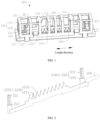
FIG. 1 is a schematic perspective diagram of an air purification device according to an embodiment of the present disclosure; -
FIG. 2 is a schematic perspective diagram of a first electrodes and a second electrode in a connected configuration according to an embodiment of the present disclosure; -
FIG. 3 is a schematic front view of a first electrodes and a second electrode in a connected configuration according to an embodiment of the present disclosure; -
FIG. 4 is a schematic front view of an air purification device according to an embodiment of the present disclosure; -
FIG. 5 is a schematic top view of an air purification device according to an embodiment of the present disclosure; and -
FIG. 6 is a schematic side view of an air purification device according to an embodiment of the present disclosure. - List of reference numerals:
-
housing 100; negativeion generating area 101;plasma generating area 102;protective cover 110;grid bar 111;frame 112; connectingrib 113;shielding portion 114;base 120;first buckle 121;second buckle 122; -
ion generation assembly 200; firstconductive member 201; secondconductive member 202;first electrode 210;first tip portion 211;basal portion 212;second electrode 220;electrode plate 221;second tip portion 222;third electrode 230;negative ion electrode 240; plasma high-voltage electrode 250;plasma ground electrode 260; and -
air purification device 1000. - Embodiments of the present disclosure will be described in detail hereinafter with reference to accompanying drawings in which the same or like reference numerals refer to the same or like elements or elements having the same or like functions throughout. The embodiments described below with reference to the accompanying drawings are illustrative and are intended for illustration only and are not to be construed as limiting the present disclosure.
- In the description of the present disclosure, it should be understood that for the description of orientations, the orientation or positional relationships indicated by the terms such as "on/upper" and "below/lower" are based on orientation or positional relationships shown in the accompanying drawings, and are used only for ease and brevity of illustration and description, rather than indicating or implying that the mentioned apparatus or element must have a particular orientation or must be constructed and operated in a particular orientation. Therefore, such terms should not be construed as limiting the present disclosure.
- In the description of the present disclosure, the terms such as "first", "second" and the like used herein are merely used for distinguishing technical features, and are not intended to indicate or imply relative importance, or implicitly point out the number of the indicated technical features, or implicitly point out the order of the indicated technical features.
- In the description of the present disclosure, unless otherwise explicitly defined, the terms such as "configure", "install/mount" and "connect" should be understood in a broad sense, and those having ordinary skills in the art can reasonably determine the specific meanings of the above terms in the present disclosure based on the specific contents of the scheme.
- The schemes in the present disclosure will be described clearly and fully in conjunction with the accompanying drawings. Apparently, the embodiments described are merely some embodiments, rather than all of the embodiments of the present disclosure.
- At present, a device that provides an air purification function by ionizing air mainly comprises a negative ion generator or a plasma generator. The negative ion generator can generate a large number of negative ions to combine with positively charged particles such as bacteria, viruses, and dust in the air, causing the particles to condense and settle, thereby reducing fine particles such as bacteria, viruses, and dust in the air. However, negative ions cannot really kill bacteria and viruses, and are not able to remove odors. The plasma generator can produce a large number of high-energy particles such as electrons and hydroxyl radicals, which can not only kill bacteria and viruses passing through the plasma area, but also decompose and purify peculiar odors in the air. However, the high-energy particles have high activity and short life, only exist in the tiny plasma area near the electrode, and cannot actively diffuse into the air to achieve an active sterilization effect, resulting in a limited range of function. It can be understood that air purification using negative ions or air purification using plasmas has its own advantages and disadvantages.
- An
air purification device 1000 provided by an embodiment of the present disclosure is suitable for use in an air conditioner, has the functions of a negative ion generator and a plasma generator, and therefore has the advantages of negative ions and plasmas. Theair purification device 1000 can actively diffuse negative ions into the air to achieve a sterilization effect, can kill bacteria and viruses in the air passing through theair purification device 1000, and also provides a certain odor removal effect, such that indoor air can be purified to improve indoor air quality. - Referring to
FIG. 1 , theair purification device 1000 according to the embodiment of the present disclosure comprises ahousing 100 and anion generation assembly 200. Thehousing 100 comprises aprotective cover 110 and abase 120. Theprotective cover 110 is connected to thebase 120, such that a chamber is formed by theprotective cover 110 and thebase 120. Theion generation assembly 200 is mounted inside the chamber. Theion generation assembly 200 comprisesfirst electrodes 210, asecond electrode 220, and athird electrode 230. Thefirst electrodes 210 arenegative ion electrodes 240 configured for generating negative ions by high-voltage discharge. Thesecond electrode 220 is spaced apart from thethird electrode 230. Thesecond electrode 220 and thethird electrode 230 are respectively connected to electrodes of a power supply, such that there is a voltage difference between thesecond electrode 220 and thethird electrode 230 to form a strong electric field, to generate plasmas. As such, the negative ions and the plasmas can be generated simultaneously, and air can be purified by the negative ions and the plasmas. - Referring to
FIG. 1 , it can be understood that theprotective cover 110 is of a hollowed-out structure. The hollowed-out structure may be arranged as a grille,, a screen, or the like. - The hollowed-out structure is formed with a plurality of through-holes. The hollowed-out structure covers the
ion generation assembly 200, and the negative ions generated can diffuse outward through the through-holes, to reduce fine particles such as bacteria, viruses, and dust in the air. In addition, air may also enter the chamber through the grille, and the plasmas kill bacteria and viruses in the air, and provides an odor removal effect. Therefore, theair purification device 1000 can take into account the advantages of negative ions purification and plasmas purification and provides a better purification effect. It should be noted that theair purification device 1000 may be mounted at an air outlet of an indoor unit of an air conditioner (not shown), an air flow generated at the air outlet during operation of the indoor unit of the air conditioner facilitates speeding up the diffusion of negative ions, and the air flowing through theair purification device 1000 is sterilized and deodorized by the plasmas. As such, indoor air can be effectively purified and the usage experience of the air conditioner can be improved. In some other embodiments of the present disclosure, theair purification device 1000 may be mounted at an air inlet of or in an air duct of the indoor unit of the air conditioner. - Referring to
FIG. 1 , it can be understood that thefirst electrodes 210 and thesecond electrode 220 are connected to thebase 120, for example, fixedly or detachably, and thethird electrode 230 is located above thesecond electrode 220 and is connected to an inner side of theprotective cover 110, for example, fixedly or detachably, such that thesecond electrode 220 is spaced apart from thethird electrode 230. Thefirst electrodes 210 and thesecond electrode 220 are electrically connected together and are connected to a high-voltage electrode of a power supply (not shown) through a firstconductive member 201, such as a conductive wire or other conductive members. The high-voltage electrode has a negative high voltage, which may range from -2 kV to -15 kV. Thethird electrode 230 is connected to a ground electrode of the power supply through a secondconductive member 202, such as a ground wire or other conductive members. Thefirst electrodes 210 are high-voltagenegative ion electrodes 240, thesecond electrode 220 is a plasma high-voltage electrode 250, and thethird electrode 230 is aplasma ground electrode 260. Thenegative ion electrode 240 forms monopolar tip corona discharge to generate negative ions. A voltage difference is formed between the plasma high-voltage electrode 250 and theplasma ground electrode 260 to generate plasmas. It can be understood that theprotective cover 110 and the base 120 are made of an insulating material, such as plastic, ceramic, etc. Theprotective cover 110 prevents a person from touching the plurality of electrodes with hand, and can also provide physical and electrical protection for the plurality of electrodes, thereby achieving higher protection performance and higher safety. - Referring to
FIG. 1 , it can be understood that thefirst electrodes 210 and thesecond electrode 220 may extend into thebase 120. For example, thebase 120 may be provided with a groove having an opening facing toward the chamber formed by theprotective cover 110 and thebase 120, and thefirst electrodes 210 and thesecond electrode 220 are placed in the groove. As such, positioning and assembly of thefirst electrodes 210 and thesecond electrode 220 are facilitated, and the size can be reduced. The firstconductive member 201 is connected to thefirst electrodes 210 and/or thesecond electrode 220 in thebase 120, for example, in the groove, and extends out from the base 120 to connect to the high-voltage electrode of the power supply. The secondconductive member 202 is connected to thethird electrode 230 in theprotective cover 110 and extends toward thebase 120. The secondconductive member 202 extends into thebase 120 and extends out from the base 120 to connect to the ground electrode of the power supply. The firstconductive member 201 and the secondconductive member 202 may extend out from the same outlet hole in the base. The above wiring method can protect the firstconductive member 201 and the secondconductive member 202, avoid messy wiring, and reduce the space occupied by wires. - Referring to
FIG. 1 , it can be understood that two functional areas are formed in theprotective cover 110, comprising a first functional area and a second functional area located in the chamber. The first functional area is a negativeion generating area 101 of thefirst electrode 210. In this embodiment, twofirst electrodes 210 are provided, i.e., twonegative ion electrodes 240 are comprised, and the twonegative ion electrodes 240 each form a negativeion generating area 101. However, the number of thefirst electrodes 210 is not limited to two. In some other embodiments, the number of thefirst electrodes 210 may be one or three or more. The second functional area is aplasma generating area 102 formed between thesecond electrode 220 and thethird electrode 230. The negative ion generating areas are located on two sides of theplasma generating area 102. After thefirst electrodes 210 and thesecond electrode 220 are energized, negative ions are generated in the negative ion generating areas, and plasmas are generated in theplasma generating area 102. To reduce the impact of mutual interference between the negative ion generating areas and theplasma generating area 102 on the purification effect, a combined structure formed by thefirst electrodes 210, thesecond electrode 220, thethird electrode 230, and theprotective cover 110 is optimized, to facilitate the miniaturization design of theair purification device 1000. Details will be described in the following embodiments. - Referring to
FIG. 2 andFIG. 3 , thefirst electrodes 210 and thesecond electrode 220 is in a connected configuration. Thesecond electrode 220 comprises anelectrode plate 221. The twonegative ion electrodes 240 are respectively connected to two ends of theelectrode plate 221. In this embodiment, firstly, thenegative ion electrodes 240 are fixed to theelectrode plate 221 by welding, wires or other means, which is not limited herein. Then, thenegative ion electrodes 240 and theelectrode plate 221 are fixed to thebase 120, and are connected to the high-voltage electrode of the same power supply through a conductive wire. As such, thenegative ion electrodes 240 and the plasma high-voltage electrode 250 are powered and supplied with the same high-voltage through the conductive wire at the same time, and there is no need to provide two sets of power supplies. Therefore, the requirement of theion generation assembly 200 for a high-voltage power supply is lowered, thereby reducing the costs. - Referring to
FIG. 2 andFIG. 3 , it can be understood that each of thenegative ion electrodes 240 comprises afirst tip portion 211, theelectrode plate 221 comprises asecond tip portion 222, and thesecond tip portion 222 is arranged facing toward thethird electrode 230. In an embodiment of the present disclosure, thefirst tip portion 211 is made of a carbon fiber material and comprises a plurality of carbon fiber bristles, and the bottom of thenegative ion electrode 240 is abasal portion 212. The carbon fiber bristles are pinched by thebasal portion 212, root portions of the carbon fiber bristles are fixed to thebasal portion 212, and the carbon fiber bristles extend out from thebasal portion 212 to form a tip structure. After a negative high voltage is applied to thefirst tip portion 211, monopolar tip corona discharge is formed to generate negative ions. The carbon fiber bristles are welded to theelectrode plate 221 through thebasal portion 212 and are electrically connected to theelectrode plate 221. As such, processing and assembly are simplified, and no wiring is needed, such that the space occupied can be reduced and miniaturization can be achieved. In some other embodiments, thefirst tip portion 211 may also be made of other conductive fibers, and thefirst tip portion 211 may also be a tooth-like structure, a needle tip structure, or other tip structures, which is not limited herein. For example, thefirst tip portion 211 may be a metal needle structure. - Referring to
FIG. 1 andFIG. 3 , it should be noted that thenegative ion electrodes 240 are respectively arranged on the two sides of the plasma high-voltage electrode 250, the twofirst tip portions 211 are respectively located on two sides of thesecond tip portion 222, and the twofirst tip portions 211 are spaced apart from thesecond tip portion 222 by a certain distance. As such, the interference of the high-voltage discharge of thefirst tip portions 211 on the electric field of theplasma generating area 102 can be reduced, the local electric field can be made more uniform, and the distribution and diffusion of negative ions can be facilitated. In some embodiments, three or morenegative ion electrodes 240 may be provided. Thenegative ion electrodes 240 are not limited to being arranged on the two sides of theelectrode plate 221, and thenegative ion electrodes 240 may also be arranged on the same side of theelectrode plate 221, such that the negativeion generating areas 101 are located on one side of theplasma generating area 102. - Referring to
FIG. 2 andFIG. 3 , in an embodiment of the present disclosure, theelectrode plate 221 is a metal plate, thethird electrode 230 is a metal bar, theelectrode plate 221 comprises a plurality of tooth-likesecond tip portions 222, and the plurality ofsecond tip portions 222 are arranged in a length direction of theelectrode plate 221 to form a sawtooth structure. Theelectrode plate 221 discharges through the sawtooth structure, and cooperates with the metal bar to generate a strong electric field to generate plasmas. It should be noted that thesecond tip portions 222 and theelectrode plate 221 are integrally formed, and both theelectrode plate 221 and the metal bar are made of stainless steel, to provide satisfactory corrosion resistance and improve the durability of the electrode structure. Theelectrode plate 221 and the metal bar may also be made of other corrosion-resistant materials. Thesecond tip portions 222 may have a shape with a large curvature radius to provide strong discharge performance, such as a needle tip or a filament, which is not limited herein. - Referring to
FIG. 1 ,FIG. 4 , andFIG. 6 , theprotective cover 110 comprises aframe 112 and a plurality of grid bars 111 connected to theframe 112. The plurality of grid bars 111 are arranged at an interval in a length direction of the base 120 to form a grille, thereby constructing the hollowed-out structure. Theframe 112 is generally rectangular. Eachgrid bar 111 is bent in an approximately U shape. Two ends of each of the grid bars 111 are respectively connected to theframe 112. The grid bars 111 and theframe 112 are integrally formed, to achieve a stable and reliable structure. A spacing is formed between adjacent grid bars 111. The negativeion generating areas 101 and theplasma generating area 102 are both in communicated with the spacing. The negative ions generated by thenegative ion electrodes 240 can diffuse outward through the spacing, and air can also enter theplasma generating area 102 through the spacing. It should be noted that the spacing may be set to have different dimensions at different positions, or may be set to have a uniform dimension. As shown inFIG. 4 , the spacing is defined as L1, and L1 ≤ 6 mm, i.e., a spacing between adjacent grid bars 111 is less than or equal to 6 mm, and the spacing is not zero. For example, the spacing may be set to 3 mm, 5 mm, etc., to ensure that a person cannot touch the electrodes in theprotective cover 110 with a finger. - Referring to
FIG. 4 , it should be noted that theframe 112 is provided with afirst buckle 121, and thebase 120 is provided with a slot corresponding to thefirst buckle 121, and thefirst buckle 121 is buckled into the slot, thus connecting theprotective cover 110 to thebase 120. As such, the assembly is facilitated. In some other embodiments, a buckle may be provided on the base and a slot may be provided on the frame, and the assembly is realized by the engagement of the buckle with the slot. After the assembly of theprotective cover 110 and thebase 120 is completed, the twofirst tip portions 211 are both exposed out of the spacing in a width direction of thebase 120, i.e., the grid bars 111 do not block thefirst tip portions 211, which is beneficial to speeding up the diffusion of negative ions, thereby improving the purification efficiency. It can be understood that after theair purification device 1000 is mounted in an air conditioner, a length direction of theprotective cover 110 is perpendicular to or form an angle with the flow direction of air, such that an air flow can enter theprotective cover 110 from the spacing on the side of theprotective cover 110 in the width direction and directly blow toward thefirst tip portion 211. When the spacing satisfies the above conditions, the distance of the spacing near thefirst electrode 210 may be appropriately increased, or the distance of the spacing corresponding to thefirst tip portion 211 may be set to be larger than the distance of the spacing at other positions, to further improve the diffusion efficiency of negative ions. - Referring to
FIG. 4 , a height of thefirst tip portion 211 is greater than a height of thebasal portion 212, and a sum of the height of thefirst tip portion 211 and the height of thebasal portion 212 is greater than a height of theframe 112, such that thefirst tip portion 211 is not completely blocked by theframe 112, i.e., it is ensured that at least part of the first tip portion is higher than theframe 112 and can be exposed out of the spacing, so as not to affect the diffusion of negative ions. In an embodiment, the height of thebasal portion 212 is set to be greater than the height of theframe 112, such that thefirst tip portion 211 can be completely exposed out of the spacing. - Referring to
FIG. 1 ,FIG. 4 , andFIG. 5 , theprotective cover 110 is further provided with a plurality of connectingribs 113 connected to the grid bars 111, and the connectingribs 113 are arranged in the length direction of theprotective cover 110. The connectingribs 113 can improve the stability of the grille structure, making the entireprotective cover 110 more solid and more reliable. The metal bar is fixed to at least one connectingrib 113 on a top wall of theprotective cover 110. The metal bar is located on a bottom surface of the connectingrib 113. The connectingrib 113 covers the metal bar to protect the metal bar, so as to prevent a human hand or other objects from accessing the metal bar from the outside of theprotective cover 110, thereby ensuring electrical safety. It can be understood that theplasma ground electrode 260 is fixed to theprotective cover 110, to save the space between theprotective cover 110 and the plasma high-voltage electrode 250, which facilitates the miniaturization design of the overall structure, and lowers the requirement of theair purification device 1000 for installation space. - Referring to
FIG. 1 andFIG. 4 , it should be noted that the plasma high-voltage electrode 250 is fixed to thebase 120, and theplasma ground electrode 260 is fixed to theprotective cover 110. By adjusting the height of theprotective cover 110, the distance between the metal bar and the sawtooth structure can be adjusted to achieve the purpose of adjusting the plasma intensity and ensuring electrical safety. The intensity of the plasmas generated may also be changed by adjusting the supply voltage. The matching relationship between the distance between the two electrodes and the supplied high-voltage electricity is adjusted according to an actual application scenario to achieve a satisfactory purification effect. - Referring to
FIG. 5, FIG. 5 is a top view of theair purification device 1000. It should be noted that in a height direction of theprotective cover 110, the metal plate and the metal bar are staggered and not aligned, i.e., the metal bar is not located exactly above the metal plate, and the direction of the electric field formed between the metal plate and the metal bar has an inclined angle. As such, the size of theair purification device 1000 is further reduced while ensuring the required distance between the metal plate and the metal bar. Moreover, in an embodiment, a length of the metal bar is greater than a length of a discharge portion of the metal plate, for example, a length of the sawtooth structure. As such, a fan-shapedplasma generating area 102 can be formed on the premise of ensuring a sufficient safety distance between the two electrodes, which is beneficial to increasing the spatial range of theplasma generating area 102 and improving the purification effect. - Referring to
FIG. 5 , it can be understood that in an embodiment, a length by which the metal bar extends in the length direction of thebase 120 is less than or equal to a length of the connectingrib 113, and a width of the metal bar is less than or equal to a width of the connectingrib 113, i.e., the connectingrib 113 can completely cover the metal bar, and a person cannot touch the metal bar with a finger from the outside of theprotective cover 110. It should be noted that connecting lugs (not shown) are respectively arranged at two ends of the metal bar, shieldingportions 114 matching the connecting lugs are respectively arranged on the twogrid bars 111, and the two connecting lugs are respectively fixedly connected to bottom surfaces of the two shieldingportions 114, such that the connecting lugs can be shielded by the shieldingportions 114, thereby further improving electrical safety. In addition, the metal bar is connected to the ground electrode of the power supply through a conductive wire. The conductive wire extends from the top wall of theprotective cover 110 to thebase 120 and is led out from the base 120 to connect to the power supply. - Referring to
FIG. 4 , in an embodiment, a distance between thefirst tip portion 211 and the metal bar is defined as L2, the distance L2 is a spacing between thefirst tip portion 211 and the metal bar in the length direction, a distance between thesecond tip portion 222 and the metal bar is defined as L3, and L2 > L3, i.e., a spacing between thefirst tip portion 211 and the metal bar needs to be greater than a spacing between thesecond tip portion 222 and the metal bar, such that the interference of the negativeion generating area 101 to theplasma generating area 102 can be reduced. It can be understood that both thefirst tip portion 211 and thesecond tip portion 222 are high-voltage electrodes, and if thefirst tip portion 211 is closer to the metal bar than thesecond tip portion 222 is, the electric field formed between thesecond tip portion 222 and the metal bar will be interfered, and the formation of theplasma generating area 102 will be affected, affecting the generation of plasmas. When the condition L2 > L3 is satisfied, thefirst tip portion 211 is spaced apart from the metal bar by a sufficiently large distance to achieve an electrode discharge effect and generate negative ions, and thesecond tip portion 222 can cooperate with the metal bar to generate a stable electric field, thereby ensuring the stability of theplasma generating area 102. - Referring to
FIG. 4 andFIG. 5 , in an embodiment, considering that thenegative ion electrodes 240 and the plasma high-voltage electrode 250 are connected to a high voltage during operation, a distance between thenegative ion electrode 240 and theprotective cover 110 is set to be greater than or equal to 3 mm, and a distance between the plasma high-voltage electrode 250 and theprotective cover 110 is also set to be greater than or equal to 3 mm. It can be understood that both thenegative ion electrodes 240 and the plasma high-voltage electrode 250 are connected to thebase 120. Therefore, the distance between thenegative ion electrode 240 and theprotective cover 110 in each direction should be not less than 3 mm, and the distance between the plasma high-voltage electrode 250 and theprotective cover 110 in each direction should be not less than 3 mm. For example, thenegative ion electrode 240 is spaced apart from theprotective cover 110 by 3 mm, 4 mm, 6 mm, etc. - Referring to
FIG. 6, FIG. 6 is a schematic side view of theair purification device 1000. Thebase 120 is further provided with asecond buckle 122 configured for connecting to an indoor unit of an air conditioner. As such, theair purification device 1000 can be conveniently and quickly assembled to the indoor unit of the air conditioner. Alternatively, a buckle may be provided on theframe 112 to connect to the indoor unit of the air conditioner. The method for mounting theair purification device 1000 on the indoor unit of the air conditioner is not limited to buckling, and bolt connection or other methods may also be used, which is not limited herein. - An embodiment of the present disclosure provides an air conditioner (not shown), comprising the
air purification device 1000 of the above embodiments. Using an indoor unit of the air conditioner as an example, theair purification device 1000 may be mounted at an air outlet of the indoor unit of the air conditioner. An air flow generated at the air outlet is beneficial to speeding up the diffusion of negative ions. The air conditioner has the advantages of negative ions and plasmas, can actively diffuse negative ions into the air to achieve a sterilization effect, can kill bacteria and viruses in the air passing through theair purification device 1000, and also provides a certain odor removal effect, such that indoor air can be purified to improve indoor air quality. - The embodiments of the present disclosure have been described in detail above in conjunction with the accompanying drawings, but the present disclosure is not limited to the above embodiments, and various changes may be made within the knowledge of those having ordinary skills in the art without departing from the scope of the present disclosure.
Claims (19)
- An air purification device comprising:a housing comprising a protective cover and a base, wherein the base is connected to the protective cover; andan ion generation assembly comprising at least one first electrode, a second electrode, and a third electrode, wherein the at least one first electrode is configured for discharging to generate negative ions, and the second electrode is spaced apart from the third electrode and is configured for cooperating with the third electrode to generate plasmas,wherein the protective cover is of a hollowed-out structure, the hollowed-out structure covers the ion generation assembly, the at least one first electrode and the second electrode are connected to the base, and the third electrode is connected to an inner side of the protective cover.
- The air purification device of claim 1, wherein the at least one first electrode and the second electrode are electrically connected, and are connected to a high-voltage electrode of a power supply through a first conductive member, and the third electrode is connected to a ground electrode of the power supply through a second conductive member.
- The air purification device of claim 2, wherein the at least one first electrode and the second electrode are fixedly connected to form a unity or are connected by a wire.
- The air purification device of claim 2, wherein:the at least one first electrode and the second electrode extend into the base, and the first conductive member is connected to the at least one first electrode or the second electrode in the base and extends out from the base to connect to the high-voltage electrode of the power supply; andthe second conductive member is connected to the third electrode in the protective cover and extends towards the base, and the second conductive member extends into the base and extends out from the base to connect to the ground electrode of the power supply.
- The air purification device of any one of claims 1 to 4, wherein the second electrode comprises an electrode plate, the electrode plate comprises a plurality of second tip portions arranged in a length direction of the electrode plate, and the at least one first electrode is connected to an end of the electrode plate.
- The air purification device of claim 5, wherein the at least one first electrode comprises at least two first electrodes, and the at least two first electrodes are divided into two groups and respectively arranged at two ends of the electrode plate, or the at least two first electrodes are both arranged at an end of the electrode plate.
- The air purification device of claim 5, wherein the second tip portion is of a tooth-like, needle-tip, or filament-like structure.
- The air purification device of any one of claims 1 to 4, wherein a connecting rib is arranged on a side wall of the protective cover away from the base, the third electrode is arranged on a side of the connecting rib facing the base, and the connecting rib, the second electrode, and the third electrode respectively extend in a length direction of the base.
- The air purification device of claim 8, wherein a length by which the third electrode extends in the length direction of the base is less than or equal to a length of the connecting rib, and a width of the third electrode is less than or equal to a width of the connecting rib.
- The air purification device of claim 8, wherein shielding portions are arranged on the side wall of the protective cover away from the base, the shielding portions are respectively located at two ends of the connecting rib, connecting portions are respectively arranged at two ends of the third electrode, and the connecting portions are connected to a side of the shielding portions facing the base.
- The air purification device of claim 8, wherein a length of the third electrode is greater than a length of a discharge portion of the second electrode.
- The air purification device of claim 8, wherein the third electrode and the second electrode are staggered in a height direction of the base.
- The air purification device of any one of claims 1 to 4, wherein the protective cover comprises a frame and a plurality of grid bars connected to the frame, the plurality of grid bars are arranged at an interval in a length direction of the base to form a grille, thereby constructing the hollowed-out structure, a spacing is formed between adjacent grid bars, and a discharge portion of the at least one first electrode and/or a discharge portion of the second electrode is exposed through the spacing in a width direction of the base.
- The air purification device of claim 13, wherein the spacing between adjacent grid bars is less than or equal to 6 mm.
- The air purification device of any one of claims 1 to 4, wherein the at least one first electrode comprises a basal portion and a first tip portion connected to a top end of the basal portion, and a height of the first tip portion is greater than a height of the basal portion.
- The air purification device of claim 15, wherein the first tip portion comprises a plurality of conductive fibers connected to the basal portion.
- The air purification device of any one of claims 1 to 4, wherein a distance between the at least one first electrode and the third electrode is greater than a distance between the second electrode and the third electrode.
- The air purification device of any one of claims 1 to 4, wherein a distance between the at least one first electrode and the protective cover is greater than or equal to 3 mm, and a distance between the second electrode and the protective cover is greater than or equal to 3 mm.
- An air conditioner, comprising an air purification device of any one of claims 1 to 18.
Applications Claiming Priority (3)
| Application Number | Priority Date | Filing Date | Title |
|---|---|---|---|
| CN202222329915.XU CN217929149U (en) | 2022-08-31 | 2022-08-31 | Air purification device and air conditioner |
| CN202211065958.XA CN117663343A (en) | 2022-08-31 | 2022-08-31 | Air purifying device and air conditioner |
| PCT/CN2023/085573 WO2024045602A1 (en) | 2022-08-31 | 2023-03-31 | Air purification device and air conditioner |
Publications (2)
| Publication Number | Publication Date |
|---|---|
| EP4582748A1 true EP4582748A1 (en) | 2025-07-09 |
| EP4582748A4 EP4582748A4 (en) | 2025-12-24 |
Family
ID=90100292
Family Applications (1)
| Application Number | Title | Priority Date | Filing Date |
|---|---|---|---|
| EP23858643.2A Pending EP4582748A4 (en) | 2022-08-31 | 2023-03-31 | AIR PURIFICATION DEVICE AND AIR CONDITIONING |
Country Status (3)
| Country | Link |
|---|---|
| US (1) | US20250161524A1 (en) |
| EP (1) | EP4582748A4 (en) |
| WO (1) | WO2024045602A1 (en) |
Family Cites Families (13)
| Publication number | Priority date | Publication date | Assignee | Title |
|---|---|---|---|---|
| JP2001321661A (en) * | 2000-05-19 | 2001-11-20 | Sharp Corp | Negative ion generator, air cleaner and air conditioner provided with the same |
| JP3099388U (en) * | 2003-07-22 | 2004-04-02 | 武田 幸一 | Negative ion generator |
| JP3852429B2 (en) * | 2003-08-06 | 2006-11-29 | 株式会社日立製作所 | Air cleaner |
| JP5868289B2 (en) * | 2012-08-22 | 2016-02-24 | 三菱電機株式会社 | Discharge device and air conditioner |
| CN103791563B (en) * | 2014-01-14 | 2016-09-14 | 秦路 | The no material consumption air purifier purified the air of a room |
| CN204757173U (en) * | 2015-07-04 | 2015-11-11 | 太和昇(厦门)科技有限公司 | Air purifier for elevator |
| US10980909B2 (en) * | 2016-03-28 | 2021-04-20 | Sharp Kabushiki Kaisha | Ion generating device and method for manufacturing ion generating device |
| IL262022B (en) * | 2018-09-27 | 2020-11-30 | Riskin Yefim | A method for disinfection of air and disinfector |
| CN211400117U (en) * | 2019-09-27 | 2020-09-01 | 四川奥洁消毒设备有限公司 | Plasma air purification device |
| CN114909759B (en) * | 2021-02-07 | 2025-12-09 | 开利公司 | Air purifying device |
| CN113124528A (en) * | 2021-04-09 | 2021-07-16 | 青岛海信日立空调系统有限公司 | Air purification device, control method thereof and air conditioner |
| CN215412375U (en) * | 2021-06-15 | 2022-01-04 | 广州市拓丰电器有限公司 | Plasma negative ion air purification device |
| CN217929149U (en) * | 2022-08-31 | 2022-11-29 | 广东美的制冷设备有限公司 | Air purification device and air conditioner |
-
2023
- 2023-03-31 EP EP23858643.2A patent/EP4582748A4/en active Pending
- 2023-03-31 WO PCT/CN2023/085573 patent/WO2024045602A1/en not_active Ceased
-
2025
- 2025-01-17 US US19/030,728 patent/US20250161524A1/en active Pending
Also Published As
| Publication number | Publication date |
|---|---|
| EP4582748A4 (en) | 2025-12-24 |
| US20250161524A1 (en) | 2025-05-22 |
| WO2024045602A1 (en) | 2024-03-07 |
Similar Documents
| Publication | Publication Date | Title |
|---|---|---|
| CN217929149U (en) | Air purification device and air conditioner | |
| US8624476B2 (en) | Ion-generating device and electrical apparatus | |
| EP2309198A1 (en) | Ventilation device | |
| KR102938374B1 (en) | Electrostatic charger and Electrostatic precipitator | |
| KR100452028B1 (en) | Indoor unit for air conditioner | |
| JPWO2018189928A1 (en) | Discharge devices and electrical equipment | |
| CN117663343A (en) | Air purifying device and air conditioner | |
| KR20130076177A (en) | Electric precipitator and air cleaner comprising the same | |
| EP4582748A1 (en) | Air purification device and air conditioner | |
| JP3726220B2 (en) | Air cleaner | |
| CN216976978U (en) | Indoor unit of air conditioner | |
| US20050095182A1 (en) | Electro-kinetic air transporter-conditioner devices with electrically conductive foam emitter electrode | |
| CN111542396B (en) | Charging equipment and dust remover | |
| CN213208150U (en) | Air sterilizer | |
| CN219107748U (en) | Air treatment equipment and air purification device | |
| KR20130022722A (en) | Electric precipitator and air cleaner comprising the same | |
| CN113578530A (en) | Air purification subassembly and air purification equipment | |
| CN220818008U (en) | Air purification device and air treatment equipment | |
| CN218884110U (en) | Air treatment equipment | |
| CN215586787U (en) | Dust collecting plate and dust collecting device | |
| CN215917804U (en) | Air purification subassembly and air purification equipment | |
| JP5484259B2 (en) | Ion generator and electrical equipment | |
| CN211619701U (en) | Elevator and air purifier in car thereof | |
| EP4145051B1 (en) | Plasma generator and plasma treatment system | |
| KR940002616B1 (en) | Electric dust collector |
Legal Events
| Date | Code | Title | Description |
|---|---|---|---|
| STAA | Information on the status of an ep patent application or granted ep patent |
Free format text: STATUS: THE INTERNATIONAL PUBLICATION HAS BEEN MADE |
|
| PUAI | Public reference made under article 153(3) epc to a published international application that has entered the european phase |
Free format text: ORIGINAL CODE: 0009012 |
|
| STAA | Information on the status of an ep patent application or granted ep patent |
Free format text: STATUS: REQUEST FOR EXAMINATION WAS MADE |
|
| 17P | Request for examination filed |
Effective date: 20250331 |
|
| AK | Designated contracting states |
Kind code of ref document: A1 Designated state(s): AL AT BE BG CH CY CZ DE DK EE ES FI FR GB GR HR HU IE IS IT LI LT LU LV MC ME MK MT NL NO PL PT RO RS SE SI SK SM TR |
|
| DAV | Request for validation of the european patent (deleted) | ||
| DAX | Request for extension of the european patent (deleted) | ||
| A4 | Supplementary search report drawn up and despatched |
Effective date: 20251124 |
|
| RIC1 | Information provided on ipc code assigned before grant |
Ipc: F24F 8/30 20210101AFI20251118BHEP Ipc: F24F 8/192 20210101ALI20251118BHEP Ipc: F24F 8/20 20210101ALI20251118BHEP Ipc: F24F 13/20 20060101ALI20251118BHEP Ipc: F24F 13/00 20060101ALI20251118BHEP Ipc: F24F 1/0071 20190101ALI20251118BHEP Ipc: A61L 9/22 20060101ALI20251118BHEP Ipc: H05H 1/24 20060101ALI20251118BHEP Ipc: F24F 130/00 20180101ALI20251118BHEP Ipc: F24F 130/20 20180101ALI20251118BHEP |