EP4582593A1 - Membrane electrode assembly for water electrolysis tank - Google Patents
Membrane electrode assembly for water electrolysis tank Download PDFInfo
- Publication number
- EP4582593A1 EP4582593A1 EP23860348.4A EP23860348A EP4582593A1 EP 4582593 A1 EP4582593 A1 EP 4582593A1 EP 23860348 A EP23860348 A EP 23860348A EP 4582593 A1 EP4582593 A1 EP 4582593A1
- Authority
- EP
- European Patent Office
- Prior art keywords
- polymer electrolyte
- electrolyte membrane
- catalytic layer
- main surface
- film
- Prior art date
- Legal status (The legal status is an assumption and is not a legal conclusion. Google has not performed a legal analysis and makes no representation as to the accuracy of the status listed.)
- Pending
Links
Images



Classifications
-
- C—CHEMISTRY; METALLURGY
- C25—ELECTROLYTIC OR ELECTROPHORETIC PROCESSES; APPARATUS THEREFOR
- C25B—ELECTROLYTIC OR ELECTROPHORETIC PROCESSES FOR THE PRODUCTION OF COMPOUNDS OR NON-METALS; APPARATUS THEREFOR
- C25B1/00—Electrolytic production of inorganic compounds or non-metals
- C25B1/01—Products
- C25B1/02—Hydrogen or oxygen
- C25B1/04—Hydrogen or oxygen by electrolysis of water
-
- C—CHEMISTRY; METALLURGY
- C25—ELECTROLYTIC OR ELECTROPHORETIC PROCESSES; APPARATUS THEREFOR
- C25B—ELECTROLYTIC OR ELECTROPHORETIC PROCESSES FOR THE PRODUCTION OF COMPOUNDS OR NON-METALS; APPARATUS THEREFOR
- C25B11/00—Electrodes; Manufacture thereof not otherwise provided for
- C25B11/04—Electrodes; Manufacture thereof not otherwise provided for characterised by the material
- C25B11/051—Electrodes formed of electrocatalysts on a substrate or carrier
- C25B11/054—Electrodes comprising electrocatalysts supported on a carrier
-
- C—CHEMISTRY; METALLURGY
- C25—ELECTROLYTIC OR ELECTROPHORETIC PROCESSES; APPARATUS THEREFOR
- C25B—ELECTROLYTIC OR ELECTROPHORETIC PROCESSES FOR THE PRODUCTION OF COMPOUNDS OR NON-METALS; APPARATUS THEREFOR
- C25B11/00—Electrodes; Manufacture thereof not otherwise provided for
- C25B11/04—Electrodes; Manufacture thereof not otherwise provided for characterised by the material
- C25B11/051—Electrodes formed of electrocatalysts on a substrate or carrier
- C25B11/055—Electrodes formed of electrocatalysts on a substrate or carrier characterised by the substrate or carrier material
- C25B11/057—Electrodes formed of electrocatalysts on a substrate or carrier characterised by the substrate or carrier material consisting of a single element or compound
- C25B11/065—Carbon
-
- C—CHEMISTRY; METALLURGY
- C25—ELECTROLYTIC OR ELECTROPHORETIC PROCESSES; APPARATUS THEREFOR
- C25B—ELECTROLYTIC OR ELECTROPHORETIC PROCESSES FOR THE PRODUCTION OF COMPOUNDS OR NON-METALS; APPARATUS THEREFOR
- C25B11/00—Electrodes; Manufacture thereof not otherwise provided for
- C25B11/04—Electrodes; Manufacture thereof not otherwise provided for characterised by the material
- C25B11/051—Electrodes formed of electrocatalysts on a substrate or carrier
- C25B11/073—Electrodes formed of electrocatalysts on a substrate or carrier characterised by the electrocatalyst material
- C25B11/075—Electrodes formed of electrocatalysts on a substrate or carrier characterised by the electrocatalyst material consisting of a single catalytic element or catalytic compound
- C25B11/081—Electrodes formed of electrocatalysts on a substrate or carrier characterised by the electrocatalyst material consisting of a single catalytic element or catalytic compound the element being a noble metal
-
- C—CHEMISTRY; METALLURGY
- C25—ELECTROLYTIC OR ELECTROPHORETIC PROCESSES; APPARATUS THEREFOR
- C25B—ELECTROLYTIC OR ELECTROPHORETIC PROCESSES FOR THE PRODUCTION OF COMPOUNDS OR NON-METALS; APPARATUS THEREFOR
- C25B11/00—Electrodes; Manufacture thereof not otherwise provided for
- C25B11/04—Electrodes; Manufacture thereof not otherwise provided for characterised by the material
- C25B11/051—Electrodes formed of electrocatalysts on a substrate or carrier
- C25B11/073—Electrodes formed of electrocatalysts on a substrate or carrier characterised by the electrocatalyst material
- C25B11/091—Electrodes formed of electrocatalysts on a substrate or carrier characterised by the electrocatalyst material consisting of at least one catalytic element and at least one catalytic compound; consisting of two or more catalytic elements or catalytic compounds
-
- C—CHEMISTRY; METALLURGY
- C25—ELECTROLYTIC OR ELECTROPHORETIC PROCESSES; APPARATUS THEREFOR
- C25B—ELECTROLYTIC OR ELECTROPHORETIC PROCESSES FOR THE PRODUCTION OF COMPOUNDS OR NON-METALS; APPARATUS THEREFOR
- C25B13/00—Diaphragms; Spacing elements
- C25B13/02—Diaphragms; Spacing elements characterised by shape or form
-
- C—CHEMISTRY; METALLURGY
- C25—ELECTROLYTIC OR ELECTROPHORETIC PROCESSES; APPARATUS THEREFOR
- C25B—ELECTROLYTIC OR ELECTROPHORETIC PROCESSES FOR THE PRODUCTION OF COMPOUNDS OR NON-METALS; APPARATUS THEREFOR
- C25B13/00—Diaphragms; Spacing elements
- C25B13/04—Diaphragms; Spacing elements characterised by the material
- C25B13/08—Diaphragms; Spacing elements characterised by the material based on organic materials
-
- C—CHEMISTRY; METALLURGY
- C25—ELECTROLYTIC OR ELECTROPHORETIC PROCESSES; APPARATUS THEREFOR
- C25B—ELECTROLYTIC OR ELECTROPHORETIC PROCESSES FOR THE PRODUCTION OF COMPOUNDS OR NON-METALS; APPARATUS THEREFOR
- C25B9/00—Cells or assemblies of cells; Constructional parts of cells; Assemblies of constructional parts, e.g. electrode-diaphragm assemblies; Process-related cell features
- C25B9/17—Cells comprising dimensionally-stable non-movable electrodes; Assemblies of constructional parts thereof
- C25B9/19—Cells comprising dimensionally-stable non-movable electrodes; Assemblies of constructional parts thereof with diaphragms
-
- C—CHEMISTRY; METALLURGY
- C25—ELECTROLYTIC OR ELECTROPHORETIC PROCESSES; APPARATUS THEREFOR
- C25B—ELECTROLYTIC OR ELECTROPHORETIC PROCESSES FOR THE PRODUCTION OF COMPOUNDS OR NON-METALS; APPARATUS THEREFOR
- C25B9/00—Cells or assemblies of cells; Constructional parts of cells; Assemblies of constructional parts, e.g. electrode-diaphragm assemblies; Process-related cell features
- C25B9/17—Cells comprising dimensionally-stable non-movable electrodes; Assemblies of constructional parts thereof
- C25B9/19—Cells comprising dimensionally-stable non-movable electrodes; Assemblies of constructional parts thereof with diaphragms
- C25B9/23—Cells comprising dimensionally-stable non-movable electrodes; Assemblies of constructional parts thereof with diaphragms comprising ion-exchange membranes in or on which electrode material is embedded
-
- C—CHEMISTRY; METALLURGY
- C25—ELECTROLYTIC OR ELECTROPHORETIC PROCESSES; APPARATUS THEREFOR
- C25B—ELECTROLYTIC OR ELECTROPHORETIC PROCESSES FOR THE PRODUCTION OF COMPOUNDS OR NON-METALS; APPARATUS THEREFOR
- C25B9/00—Cells or assemblies of cells; Constructional parts of cells; Assemblies of constructional parts, e.g. electrode-diaphragm assemblies; Process-related cell features
- C25B9/60—Constructional parts of cells
-
- C—CHEMISTRY; METALLURGY
- C25—ELECTROLYTIC OR ELECTROPHORETIC PROCESSES; APPARATUS THEREFOR
- C25B—ELECTROLYTIC OR ELECTROPHORETIC PROCESSES FOR THE PRODUCTION OF COMPOUNDS OR NON-METALS; APPARATUS THEREFOR
- C25B9/00—Cells or assemblies of cells; Constructional parts of cells; Assemblies of constructional parts, e.g. electrode-diaphragm assemblies; Process-related cell features
- C25B9/70—Assemblies comprising two or more cells
- C25B9/73—Assemblies comprising two or more cells of the filter-press type
- C25B9/77—Assemblies comprising two or more cells of the filter-press type having diaphragms
-
- Y—GENERAL TAGGING OF NEW TECHNOLOGICAL DEVELOPMENTS; GENERAL TAGGING OF CROSS-SECTIONAL TECHNOLOGIES SPANNING OVER SEVERAL SECTIONS OF THE IPC; TECHNICAL SUBJECTS COVERED BY FORMER USPC CROSS-REFERENCE ART COLLECTIONS [XRACs] AND DIGESTS
- Y02—TECHNOLOGIES OR APPLICATIONS FOR MITIGATION OR ADAPTATION AGAINST CLIMATE CHANGE
- Y02E—REDUCTION OF GREENHOUSE GAS [GHG] EMISSIONS, RELATED TO ENERGY GENERATION, TRANSMISSION OR DISTRIBUTION
- Y02E60/00—Enabling technologies; Technologies with a potential or indirect contribution to GHG emissions mitigation
- Y02E60/30—Hydrogen technology
- Y02E60/36—Hydrogen production from non-carbon containing sources, e.g. by water electrolysis
Definitions
- Fig. 1 is a cross-sectional view schematically illustrating a configuration example of a membrane electrode assembly 6 according to an embodiment of the present invention.
- the membrane electrode assembly 6 includes a polymer electrolyte membrane 1, an anode catalytic layer 2 (first electrode catalytic layer) and a cathode catalytic layer 3 (second electrode catalytic layer) respectively disposed on a first main surface 1A and a second main surface 1B of the polymer electrolyte membrane 1, an outer peripheral film 4, an adhesive film (first adhesive film) 5A, and an adhesive film (second adhesive film) 5B.
- the outer shape of the anode catalytic layer 2 and the outer shape of the cathode catalytic layer 3 are substantially the same, and the outer shape of the polymer electrolyte membrane 1 is larger than the outer shapes of the anode catalytic layer 2 and the cathode catalytic layer 3.
- the outer shape of the polymer electrolyte membrane 1 and the outer shapes of the anode catalytic layer 2 and the cathode catalytic layer are not particularly limited, and, for example, may be a rectangle (including a square).
- the outer shape dimension of the polymer electrolyte membrane 1 is larger than the outer shape dimensions of the anode catalytic layer 2 and the cathode catalytic layer.
- the outer shape dimension of the polymer electrolyte membrane 1 when the shape of the polymer electrolyte membrane 1 is a rectangle is desirably is 1.05 to 1.25 times the outer shape dimension when the anode catalytic layer 2 and the cathode catalytic layer are a rectangle in each of the length direction and the width direction, and can be adjusted according to the use environment in a water electrolysis cell.
- the polymer electrolyte membrane 1 can be formed with a polymer material having proton conductivity, such as a fluorine-based electrolyte membrane and a hydrocarbon-based polymer electrolyte membrane.
- a fluorine-based electrolyte membrane examples include Nafion (registered trademark) manufactured by DuPont Co., Flemion (registered trademark) manufactured by Asahi Glass Co., Ltd., Aciplex (registered trademark) manufactured by Asahi Kasei Corp., and Gore Select (registered trademark) manufactured by Gore Co.
- hydrocarbon-based polymer electrolyte membrane examples include electrolyte membranes of sulfonated polyether ketone, sulfonated polyether sulfone, sulfonated polyether ether sulfone, sulfonated polysulfide, and sulfonated polyphenylene.
- the polymer electrolyte membrane 1 may have a thickness of, for example, 0.05 to 0.25 mm.
- the cathode catalytic layer 3 is disposed in the center of the second main surface 1B of the polymer electrolyte membrane 1.
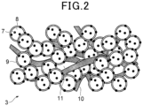
- Fig. 2 is a cathode cross-sectional view schematically illustrating a configuration of the cathode catalytic layer 3 of the present embodiment.
- the cathode catalytic layer 3 contains a cathode catalyst particle 7, a polymer electrolyte 9, and a fibrous material 10.
- the cathode catalyst particle 7 is a cathode catalyst particle for performing a reduction reaction by protons in a cathode solution.
- platinum group elements metals, or alloys, oxides, and complex oxides of the metals
- platinum group elements include platinum, palladium, ruthenium, iridium, rhodium, and osmium
- metals include iron, lead, copper, chromium, cobalt, nickel, manganese, vanadium, molybdenum, gallium, and aluminum.
- the complex oxide described herein refers to an oxide composed of two types of metals.
- the cathode catalyst particles 7 are made of one or more metals selected from platinum, gold, palladium, rhodium, ruthenium, and iridium, electrode reactivity is excellent, and an electrode reaction can be efficiently and stably performed.
- the cathode catalyst particles 7 are preferably made of one or more metals selected from platinum, gold, palladium, rhodium, ruthenium, and iridium because they exhibit high activity.
- the above-described catalyst is generally carried by an electron-conductive catalyst carrier 8.
- a carbon particle is generally used.
- the type of the carbon particle is not limited as long as the particle is a microparticle and electrically conductive and is not affected by the catalyst.
- the carbon particle for example, carbon black or graphite, black lead, activated carbon, carbon fiber, carbon nanotube, or fullerene can be used.
- the average particle size of the carbon particle is preferably within a range of 10 nm or more and 1000 nm or less, and more preferably within a range of 10 nm or more and 100 nm or less. As described herein, the term average particle size refers to an average particle size calculated from an SEM image.
- Fig. 3 is a cross-sectional view schematically illustrating a configuration of the anode catalytic layer 2 of the present embodiment.
- the anode catalytic layer 2 contains an anode catalyst particle 12 and a polymer electrolyte 9. Further, the anode catalytic layer 2 may contain a fibrous material 10.
- the anode catalyst particle 12 is an anode catalyst particle for performing an oxidation reaction in an anode solution.
- the average fiber diameter of the carbon fibers is preferably 300 nm or less and more preferably 200 nm or less.
- the average fiber diameter of the carbon fibers is 300 nm or less, appropriate thinness for a fibrous material contained in the cathode catalytic layer can be ensured.
- the average fiber diameter of the carbon fibers is 50 nm or more, appropriate thickness can be ensured so that the strength of the cathode catalytic layer is enhanced, and the effect of suppressing occurrence of cracks can be obtained.
- the polymer fibers to be used include ionomer-adsorbing fibers having the property of adsorbing polymer electrolyte, electrically conductive polymer nanofibers, and proton conductive fibers.
- the ionomer adsorbing amount of the ionomer-adsorbing fibers is 10 mg or more per 1 g of the ionomer-adsorbing fibers, and polymer fibers having at least one cation exchange group, for example, are used.
- Use of the proton-conducting fibers may improve proton conductivity.
- the proton-conducting fibers are polymer fibers obtained by processing a proton conductive polymer electrolyte into fibers.
- the average fiber length of the polymer fibers is preferably in a range of 1.0 ⁇ m or more and 40 ⁇ m or less.
- pores 11 having a suitable size can be formed in the cathode catalytic layer.
- Examples of a fibrous material 13 used in the anode catalytic layer include ionomer-adsorbing fibers having the property of adsorbing a polymer electrolyte, electrically conductive polymer nanofibers, and proton conductive fibers.
- the same material as the polymer fibers used in the cathode catalytic layer can also be used.
- the average fiber length of the fibrous material 13 is preferably in a range of 1.0 ⁇ m or more and 40 ⁇ m or less.
- pores 11 having a suitable size can be formed in the anode catalytic layer.
- an outer peripheral film 4 is disposed to surround an outer peripheral surface 1G of the polymer electrolyte membrane 1 and has an annular shape.
- the outer peripheral film 4 has an opening 4P corresponding to the outer shape of the polymer electrolyte membrane 1, and the polymer electrolyte membrane 1 is accommodated in the opening 4P of the outer peripheral film 4.
- the outer shape of the opening 4P of the outer peripheral film 4 may be a shape corresponding to the outer shape of the polymer electrolyte membrane 1, for example, a rectangular (including a square).
- the outer shape of the outer peripheral film 4 is also not particularly limited and may be rectangular (including a square) or the like.
- the distance between the opening 4P of the outer peripheral film 4 and the outer peripheral surface 1G of the polymer electrolyte membrane 1 is preferably 20 mm or less.
- the width 4W in the radial direction of the ring of the outer peripheral film 4 is not particularly limited, but can be, for example, 100 to 300 mm.
- the thickness of the outer peripheral film 4 is preferably within ⁇ 10% of the thickness of the polymer electrolyte membrane 1. This reduces a height difference between the main surface of the outer peripheral film 4 and the main surface of the polymer electrolyte membrane 1, with the result that sealing properties against liquid are excellent when the membrane electrode assembly 6 is sandwiched by gaskets and separators as described later.
- the outer peripheral film 4 may be, for example, a resin film.
- resins include polyethylene terephthalate and polyurethane.
- the material of the outer peripheral film 4 preferably does not contain polymer electrolyte.
- An outer peripheral film 4 made of polyurethane is likely to follow swelling or deformation of the polymer electrolyte membrane.
- An outer peripheral film made of polyethylene terephthalate has excellent strength.
- Adhesive films 5A and 5B each have a substrate layer 51 and an adhesive agent layer 52.
- An example of the substrate layer 51 is a resin film of polyethylene terephthalate, polyurethane, or the like.
- the substrate layer 51 may have a thickness of 25 to 100 ⁇ m.
- a substrate layer 51 made of polyurethane is likely to follow swelling or deformation of the polymer electrolyte membrane.
- a substrate layer 51 made of polyethylene terephthalate has excellent strength.
- Examples of the adhesive agent layer 52 is an acrylic-based adhesive agent layer, a urethane-based adhesive agent layer, and a rubber-based adhesive agent layer.
- the adhesive agent layer 52 may have a thickness of 5 to 25 ⁇ m.
- the adhesive agent layer 52 of the adhesive film 5A is adhered to the annular non-covered section 1AN of the polymer electrolyte membrane 1 and to a main surface 4A of the outer peripheral film 4 at the same side as the first main surface 1A of the polymer electrolyte membrane 1.
- the adhesive agent layer 52 of the adhesive film 5B is adhered to the annular non-covered section 1BN of the polymer electrolyte membrane 1 and to a main surface 4B of the outer peripheral film 4 at the same side as the second main surface 1B of the polymer electrolyte membrane 1.
- the adhesive films 5A and 5B are respectively adhered to regions covering the annular non-covered sections 1AN and 1BN of the polymer electrolyte to the main surfaces of the outer peripheral film 4, the polymer electrolyte membrane 1 and the outer peripheral film 4 are fixed.
- the thickness of the adhesive films 5A and 5B is not particularly limited but is preferably 30 to 125 ⁇ m.
- the thickness of the adhesive films 5A and 5B is preferably smaller than the thickness of each of the cathode catalytic layer 3 and the anode catalytic layer 2.
- the peeling strength of the adhesive films 5A and 5B is preferably 0.3 N/25 mm or more with a polyimide film. In this case, the peeling of the adhesive films 5A and 5B can be suppressed when producing the membrane electrode assembly 6 (when coating an ink of an electrode catalytic layer), when assembling a water electrolysis cell using the membrane electrode assembly, or when using the water electrolysis cell.
- the adhesive films 5A and 5B cover at least part of the respective main surfaces of the outer peripheral film 4, but preferably cover the whole of the main surfaces of the outer peripheral film 4.
- the anode catalytic layer 2 and the cathode catalytic layer 3 of the present embodiment can be produced by preparing a slurry for an electrode catalytic layer, coating a substrate or the like with the slurry, and drying the coat.
- a membrane electrode assembly 6 is prepared by, as shown in Fig. 1 , disposing the outer peripheral film 4 outside the outer peripheral surface of the polymer electrolyte membrane 1 and adhering the adhesive films 5A and 5B to a range covering the annular non-covered sections 1AN and 1BN of the polymer electrolyte membrane 1 to the main surfaces 4A and 4B of the outer peripheral film 4 respectively. Note that there is no problem in bonding the polymer electrolyte membrane 1 and the outer peripheral film 4 with the adhesive films 5A and 5B before forming the anode catalytic layer 2 and the cathode catalytic layer 3.
- the outer shape dimension of the polymer electrolyte membrane 1 having a rectangular shape is desirably 1.05 to 1.25 times the outer shape dimension of the anode catalytic layer 2 and the cathode catalytic layer 3 having a rectangular shape in each of the length direction and the width direction, and is adjusted according to the use environment in a water electrolysis cell.
- the annular gasket 23A has an opening in the center, the anode catalytic layer 2 and the gas diffusion layer 22A at the anode side can be accommodated in the opening, and the annular gasket 23A does not overlap the cathode catalytic layer 3 and the gas diffusion layer 22C at the cathode side.
- the polymer electrolyte membrane 1, the anode catalytic layer 2, the gas diffusion layer 22A at the anode side, the cathode catalytic layer 3, and the gas diffusion layer 22C at the cathode side are accommodated in a space V formed by the separator 26A, the separator 26C, and a gasket structure GK, and are sealed by the gasket structure GK such that liquid does not leak from the space V.
- the gasket structure GK is a laminate containing the annular gasket 23C, the adhesive film 5B, the outer peripheral film 4, the adhesive film 5A, and the annular gasket 23A.
- annular PET film with a thickness of 188 ⁇ m as the outer peripheral film 4 was disposed to surround the outer periphery of a Nafion (registered trademark) membrane (thickness: 180 to 200 ⁇ m) as the polymer electrolyte membrane 1.
- a 25 ⁇ m thick annular adhesive PET film having an opening with the same size as the outer shape of the anode catalytic layer 2 and the cathode catalytic layer and having an outer shape with the same size of the outer shape of the outer peripheral film 4, as the adhesive film 5A was bonded to the first main surface 1A of the polymer electrolyte membrane 1 and the main surface 4A in the outer peripheral film 4 at the same side as the first main surface 1A.
- the outer shape of the prepared Nafion (registered trademark) membrane had a dimension that is 1.1 times the outer shape of the anode and cathode catalytic layers in each of the length direction and the width direction.
- the bonding condition was a temperature of 23 ⁇ 2°C, a pressure of 0.1 MPa, and a speed of 2 m/min.
- the peeling strength of the adhesive PET film was measured as a 180-degree peeling strength under the conditions in accordance with JIS Z 0237 in the environment of a temperature of 23 ⁇ 2°C and a relative humidity of 65 ⁇ 5%RH. The result was 0.35 N/25 mm for a polyimide film.
- a Nafion (registered trademark) dispersion liquid manufactured by Wako Pure Chemical Industries, Ltd.
- TEC61E54 PtRu/C catalyst manufactured by Tanaka Kikinzoku Kogyo K.K.
- the blending amount of the fibrous material was determined to be 1.0 time the mass of the carrier in the catalyst-carrying particles. It was confirmed that the carbon fibers had an average fiber diameter of 150 nm.
- the obtained slurry for a cathode catalytic layer was applied to one surface of the prepared substrate by die coating such that the total amount of Pt and Ru carried per electrode area was 0.5 mg/cm 2 . Thereafter, the coat was dried in a furnace at 80°C to obtain a laminate in which a cathode catalytic layer was formed on one surface of the polymer electrolyte membrane.
- a Nafion (registered trademark) dispersion liquid manufactured by Wako Pure Chemical Industries, Ltd.
- a solvent was appropriately used to prepare a catalyst ink for an anode catalytic layer.
- the blending amount of the fibrous material was determined to be 0.01 time the mass of the anode catalytic layer. It was confirmed that the fibrous material had an average fiber diameter of 400 nm.
- the obtained slurry for an anode catalytic layer was applied to a surface of the prepared substrate on which the PtRu catalytic layer was not formed by die coating such that the total amount of iridium oxide carried per electrode area was 1.0 mg/cm 2 . Thereafter, the coat was dried in a furnace at 80°C to obtain a membrane electrode assembly for a water electrolysis cell.
- a membrane electrode assembly for a water electrolysis cell was obtained in the same procedure as in Example 1, except that an adhesive PET film having a peeling strength for a polyimide film of 0.10 N/25 mm was used.
- a membrane electrode assembly for a water electrolysis cell was obtained in the same procedure as in Example 1, except that an adhesive PET film having a peeling strength for a polyimide film of 0.28 N/25 mm was used.
Landscapes
- Chemical & Material Sciences (AREA)
- Engineering & Computer Science (AREA)
- Chemical Kinetics & Catalysis (AREA)
- Electrochemistry (AREA)
- Materials Engineering (AREA)
- Metallurgy (AREA)
- Organic Chemistry (AREA)
- Inorganic Chemistry (AREA)
- Electrolytic Production Of Non-Metals, Compounds, Apparatuses Therefor (AREA)
- Fuel Cell (AREA)
Abstract
Description
- The present invention relates to a membrane electrode assembly for a water electrolysis cell.
- In recent years, moves to use hydrogen, which is usable as CO2 free energy that can be generated from various resources, as primary energy have accelerated toward achievement of becoming carbon neutral. Especially, a method of performing electrolysis of water using renewable energy is seen as a promising method for producing hydrogen.
- As a method of water electrolysis, alkaline water electrolysis and proton exchange membrane (PEM) water electrolysis are generally known. Particularly, proton exchange membrane water electrolysis is attracting attention as a method enabling miniaturization due to highly efficient operation. A representative configuration of a proton exchange membrane water electrolysis apparatus includes a membrane electrode assembly (
Fig. 2 ) in which an electrode catalytic layer is disposed on both surfaces of a proton-conducting polymer electrolyte membrane, as well as collectors and terminal plates outside the membrane electrode assembly (see PTL 1). - PTL 1:
JP H3-74670 - In order to enhance sealing properties against liquid in a membrane electrode assembly or a water electrolysis cell apparatus including a membrane electrode assembly, it is conceivable to use, as part of a gasket, the peripheral region not covered with an electrode catalytic layer in a polymer electrolyte membrane.
- However, since a polymer electrolyte membrane is an expensive material, and the peripheral region not covered with an electrode catalytic layer in a polymer electrolyte membrane that does not contribute to a reaction such as electrolysis in the first place, the above-described configuration to use a polymer electrolyte membrane as part of a gasket is not necessarily an adequate configuration.
- The present invention has been made in view of the above-described problem, and has as its object to provide a membrane electrode assembly for a water electrolysis cell which can reduce the amount of a polymer electrolyte membrane used, while maintaining sealing properties against liquid.
-
- [1] A membrane electrode assembly for a water electrolysis cell including:
- a polymer electrolyte membrane having a first main surface and a second main surface;
- a first electrode catalytic layer disposed on the first main surface of the polymer electrolyte membrane;
- a second electrode catalytic layer disposed on the second main surface of the polymer electrolyte membrane;
- an annular outer peripheral film disposed to surround an outer peripheral surface of the polymer electrolyte membrane; and
- a first adhesive film having a substrate layer and an adhesive agent layer, in which
- the first main surface of the polymer electrolyte membrane has a first annular non-covered section that is not covered with the first electrode catalytic layer along the outer periphery of the first main surface, and
- the adhesive agent layer of the first adhesive film is adhered to the first annular non-covered section of the polymer electrolyte membrane and to a main surface of the outer peripheral film at the same side as the first main surface of the polymer electrolyte membrane.
- [2] The membrane electrode assembly for a water electrolysis cell according to [1], further including a second adhesive film having a substrate layer and an adhesive agent layer, in which
- the second main surface of the polymer electrolyte membrane has a second annular non-covered section that is not covered with the second electrode catalytic layer along the outer periphery of the second main surface, and
- the adhesive agent layer of the second adhesive film is adhered to the second annular non-covered section of the polymer electrolyte membrane and to a main surface of the outer peripheral film at the same side as the second main surface of the polymer electrolyte membrane.
- [3] The membrane electrode assembly for a water electrolysis cell according to [1] or [2], in which the outer peripheral film has a thickness that is within ±10% of the thickness of the polymer electrolyte membrane.
According to the above-described configuration, a height difference between the outer peripheral film and the polymer electrolyte membrane can be reduced, and therefore the outer peripheral film and the polymer electrolyte membrane can be fixed with higher adhesion by the adhesive film. - [4] The membrane electrode assembly for a water electrolysis cell according to any one of [1] to [3], in which the adhesive film has a peeling strength of 0.3 N/25 mm or more with a polyimide film.
According to the above-described configuration, the adhesion is sufficient, and therefore peeling of the adhesive film caused by deformation or the like of the polymer electrolyte membrane hardly occurs, and the configuration of the membrane electrode assembly is easily maintained. - [5] A water electrolysis cell including the membrane electrode assembly for a water electrolysis cell according to any one of [1] to [4].
- According to the present invention, there can be obtained a membrane electrode assembly for a water electrolysis cell in which the amount of the polymer electrolyte membrane used is small.
-
-
Fig. 1 is a cross-sectional schematic view of a structure of a membrane electrode assembly for a water electrolysis cell in an embodiment. -
Fig. 2 is a cross-sectional schematic view of a cathode catalytic layer of a membrane electrode assembly for a water electrolysis cell in an embodiment. -
Fig. 3 is a cross-sectional schematic view of an anode catalytic layer of a membrane electrode assembly for a water electrolysis cell in an embodiment. -
Fig. 4 is a cross-sectional schematic view of a water electrolysis cell in an embodiment. - With reference to the accompanying drawings, embodiments of the present invention will be described. The below-described embodiments do not limit the invention and are merely examples, and the present invention is not identified by features described as embodiments. Embodiments can be variously modified within the technical range specified by claims described in CLAIMS. Further, the drawings are schematic, and the relationships between the thickness and the planar dimensions, the ratio of the thicknesses of the respective layers, and the like are different from the actual ones.
-
Fig. 1 is a cross-sectional view schematically illustrating a configuration example of amembrane electrode assembly 6 according to an embodiment of the present invention. Themembrane electrode assembly 6 includes apolymer electrolyte membrane 1, an anode catalytic layer 2 (first electrode catalytic layer) and a cathode catalytic layer 3 (second electrode catalytic layer) respectively disposed on a firstmain surface 1A and a secondmain surface 1B of thepolymer electrolyte membrane 1, an outerperipheral film 4, an adhesive film (first adhesive film) 5A, and an adhesive film (second adhesive film) 5B. - When viewed in a direction facing the first main surface of the
polymer electrolyte membrane 1, the outer shape of the anodecatalytic layer 2 and the outer shape of the cathodecatalytic layer 3 are substantially the same, and the outer shape of thepolymer electrolyte membrane 1 is larger than the outer shapes of the anodecatalytic layer 2 and the cathodecatalytic layer 3. Note that the outer shape of thepolymer electrolyte membrane 1 and the outer shapes of the anodecatalytic layer 2 and the cathode catalytic layer are not particularly limited, and, for example, may be a rectangle (including a square). - Therefore, the outer shape dimension of the
polymer electrolyte membrane 1 is larger than the outer shape dimensions of the anodecatalytic layer 2 and the cathode catalytic layer. For ensuring adhesion between theadhesive films polymer electrolyte membrane 1, the outer shape dimension of thepolymer electrolyte membrane 1 when the shape of thepolymer electrolyte membrane 1 is a rectangle is desirably is 1.05 to 1.25 times the outer shape dimension when the anodecatalytic layer 2 and the cathode catalytic layer are a rectangle in each of the length direction and the width direction, and can be adjusted according to the use environment in a water electrolysis cell. - As described above, the sizes of the anode
catalytic layer 2 and the cathodecatalytic layer 3 are smaller than the outer shape of thepolymer electrolyte membrane 1. Therefore, annular non-covered sections 1AN and 1BN that are not covered with the anodecatalytic layer 2 and the cathodecatalytic layer 3 are respectively formed along the outer periphery of thepolymer electrolyte membrane 1 on the firstmain surface 1A at the anodecatalytic layer 2 side of thepolymer electrolyte membrane 1 and on the secondmain surface 1B at the cathodecatalytic layer 3 side of thepolymer electrolyte membrane 1. The annular non-covered sections 1AN and 1BN may have a width NW of 10 to 100 mm. - The
polymer electrolyte membrane 1 can be formed with a polymer material having proton conductivity, such as a fluorine-based electrolyte membrane and a hydrocarbon-based polymer electrolyte membrane. Examples of the fluorine-based polymer electrolyte membrane include Nafion (registered trademark) manufactured by DuPont Co., Flemion (registered trademark) manufactured by Asahi Glass Co., Ltd., Aciplex (registered trademark) manufactured by Asahi Kasei Corp., and Gore Select (registered trademark) manufactured by Gore Co. Examples of the hydrocarbon-based polymer electrolyte membrane to be used include electrolyte membranes of sulfonated polyether ketone, sulfonated polyether sulfone, sulfonated polyether ether sulfone, sulfonated polysulfide, and sulfonated polyphenylene. Thepolymer electrolyte membrane 1 may have a thickness of, for example, 0.05 to 0.25 mm. - The cathode
catalytic layer 3 is disposed in the center of the secondmain surface 1B of thepolymer electrolyte membrane 1.Fig. 2 is a cathode cross-sectional view schematically illustrating a configuration of the cathodecatalytic layer 3 of the present embodiment. The cathodecatalytic layer 3 contains acathode catalyst particle 7, apolymer electrolyte 9, and afibrous material 10. Thecathode catalyst particle 7 is a cathode catalyst particle for performing a reduction reaction by protons in a cathode solution. - As the
cathode catalyst particle 7, platinum group elements, metals, or alloys, oxides, and complex oxides of the metals can be used. Examples of the platinum group elements include platinum, palladium, ruthenium, iridium, rhodium, and osmium, and examples of the metals include iron, lead, copper, chromium, cobalt, nickel, manganese, vanadium, molybdenum, gallium, and aluminum. The complex oxide described herein refers to an oxide composed of two types of metals. When thecathode catalyst particles 7 are made of one or more metals selected from platinum, gold, palladium, rhodium, ruthenium, and iridium, electrode reactivity is excellent, and an electrode reaction can be efficiently and stably performed. Thecathode catalyst particles 7 are preferably made of one or more metals selected from platinum, gold, palladium, rhodium, ruthenium, and iridium because they exhibit high activity. - The above-described catalyst is generally carried by an electron-
conductive catalyst carrier 8. As thecatalyst carrier 8, a carbon particle is generally used. The type of the carbon particle is not limited as long as the particle is a microparticle and electrically conductive and is not affected by the catalyst. As the carbon particle, for example, carbon black or graphite, black lead, activated carbon, carbon fiber, carbon nanotube, or fullerene can be used. The average particle size of the carbon particle is preferably within a range of 10 nm or more and 1000 nm or less, and more preferably within a range of 10 nm or more and 100 nm or less. As described herein, the term average particle size refers to an average particle size calculated from an SEM image. Carbon particles having an average particle size within a range of 10 nm or more and 1,000 nm or less are preferable because the catalytic activity and stability improve. Further, carbon particles having an average particle size within a range of 10 nm or more and 1000 nm or less are preferable because an electron-conductive path is easily formed. - As shown in
Fig. 1 , the anodecatalytic layer 2 is disposed in the center of the firstmain surface 1A of thepolymer electrolyte membrane 1.Fig. 3 is a cross-sectional view schematically illustrating a configuration of the anodecatalytic layer 2 of the present embodiment. The anodecatalytic layer 2 contains ananode catalyst particle 12 and apolymer electrolyte 9. Further, the anodecatalytic layer 2 may contain afibrous material 10. Theanode catalyst particle 12 is an anode catalyst particle for performing an oxidation reaction in an anode solution. - Examples of the
anode catalyst particle 12 contained in the anode catalytic layer include metals contained in the platinum group, metals other than the metals contained in the platinum group, or alloys, oxides, complex oxides, and carbides thereof. Among these, ruthenium, rhodium, palladium, iridium, platinum, and alloys containing at least one thereof have high catalytic activity and are therefore preferable. Note that the catalyst particle may be one of the above-described examples or a combination of two or more thereof. - As the
polymer electrolyte 9, one having proton conductivity is used, and the material of thepolymer electrolyte membrane 1 can also be used. Examples of thepolymer electrolyte 9 to be used include a fluorine-based polymer electrolyte and a hydrocarbon-based polymer electrolyte. An example of the fluorine-based polymer electrolyte is a material based on Nafion (registered trademark) manufactured by DuPont Co. Examples of the hydrocarbon-based polymer electrolyte to be used include electrolytes of sulfonated polyether ketone, sulfonated polyether sulfone, sulfonated polyether ether sulfone, sulfonated polysulfide, and sulfonated polyphenylene. - As the
fibrous material 10 used in the cathode catalytic layer, carbon fibers and polymer fibers can be used. Examples of the carbon fibers include carbon fibers, carbon nanotubes, and carbon nanohoms. In particular, carbon fibers or carbon nanotubes are preferable in terms of electrical conductivity and dispersibility. The blending amount of carbon fibers is preferably in a range of 0.3 time or more and 1.5 times or less the mass of the carrier in the catalyst-carrying particles. When the content of carbon fibers is in the above-described numerical value range, a suitable amount ofpores 11 having a suitable size can be formed in the cathode catalytic layer. - When the
fibrous material 10 is carbon fibers, the average fiber diameter of the carbon fibers is preferably 300 nm or less and more preferably 200 nm or less. When the average fiber diameter of the carbon fibers is 300 nm or less, appropriate thinness for a fibrous material contained in the cathode catalytic layer can be ensured. When the average fiber diameter of the carbon fibers is 50 nm or more, appropriate thickness can be ensured so that the strength of the cathode catalytic layer is enhanced, and the effect of suppressing occurrence of cracks can be obtained. - Further, when the
fibrous material 10 is carbon fibers, the average fiber length of the carbon fibers is preferably in a range of 1.0 µm or more 20 µm or less. When the average fiber length of the carbon fibers is in the above-described numerical value range, pores 11 having a suitable size can be formed in the cathode catalytic layer. - When the
fibrous material 10 is polymer fibers, examples of the polymer fibers to be used include ionomer-adsorbing fibers having the property of adsorbing polymer electrolyte, electrically conductive polymer nanofibers, and proton conductive fibers. The ionomer adsorbing amount of the ionomer-adsorbing fibers is 10 mg or more per 1 g of the ionomer-adsorbing fibers, and polymer fibers having at least one cation exchange group, for example, are used. Use of the proton-conducting fibers may improve proton conductivity. The proton-conducting fibers are polymer fibers obtained by processing a proton conductive polymer electrolyte into fibers. As the material for forming the proton-conducting fibers, a fluorine-based polymer electrolyte, a hydrocarbon-based polymer electrolyte, and the like can be used. In addition, polymer fibers in which a cation exchange group such as a hydroxyl group, a carbonyl group, a sulfonic acid group, a phosphorous acid group, or an amino group is added to a terminal group of a polymer structure can be used. The amount of ionomers adsorbed to the ionomer-adsorbing fibers can be calculated by bringing the ionomer-adsorbing fibers into contact with a dispersion liquid in which ionomers are dispersed at a predetermined concentration, filtering the obtained product through a predetermined filter (for example, aperture: 0.3 to 0.5 µm), and measuring the concentration of ionomers contained in the filtrate. Use of proton-conducting fibers may improve proton conductivity. - The blending amount of polymer fibers is preferably in a range of 0.05 time or more and 0.3 time or less the mass of the carrier in the catalyst-carrying particles. When the content of polymer fibers is in the above-described numerical value range, a suitable amount of
pores 11 having a suitable size can be formed in the cathode catalytic layer. - When the
fibrous material 10 is polymer fibers, the average fiber diameter of the polymer fibers is preferably 500 nm or less and more preferably 400 nm or less. When the average fiber diameter of polymer fibers is 500 nm or less, appropriate thinness for a fibrous material contained in the cathode catalytic layer can be ensured. When the average fiber diameter of polymer fibers is 100 nm or more, appropriate thickness can be ensured so that the strength of the cathode catalytic layer is enhanced, and the effect of suppressing occurrence of cracks can be obtained. - Further, when the
fibrous material 10 is polymer fibers, the average fiber length of the polymer fibers is preferably in a range of 1.0 µm or more and 40 µm or less. When the average fiber length of polymer fibers is in the above-described numerical value range, pores 11 having a suitable size can be formed in the cathode catalytic layer. - Further, only one of these fibrous materials may be used alone, or two or more thereof may be used in combination, or conductive fibers and polymer fibers may be used in combination.
- Examples of a
fibrous material 13 used in the anode catalytic layer include ionomer-adsorbing fibers having the property of adsorbing a polymer electrolyte, electrically conductive polymer nanofibers, and proton conductive fibers. The same material as the polymer fibers used in the cathode catalytic layer can also be used. - The blending amount of the
fibrous material 13 is preferably in a range of 0.005 time or more and 0.2 time or less the mass of the catalyst particles. When the content of thefibrous material 13 is in the above-described numerical value range, a suitable amount ofpores 11 having a suitable size can be formed in the anode catalytic layer. - The average fiber diameter of the
fibrous material 13 is preferably 500 nm or less and more preferably 400 nm or less. When the average fiber diameter of the polymer fibers is 500 nm or less, appropriate thinness for a fibrous material contained in the anode catalytic layer can be ensured. When the average fiber diameter of the polymer fibers is 100 nm or more, appropriate thickness can be ensured so that the strength of the anode catalytic layer is enhanced, and the effect of suppressing occurrence of cracks can be obtained. - The average fiber length of the
fibrous material 13 is preferably in a range of 1.0 µm or more and 40 µm or less. When the average fiber length of polymer fibers is in the above-described numerical value range, pores 11 having a suitable size can be formed in the anode catalytic layer. - As shown in
Fig. 1 , an outerperipheral film 4 is disposed to surround an outerperipheral surface 1G of thepolymer electrolyte membrane 1 and has an annular shape. The outerperipheral film 4 has anopening 4P corresponding to the outer shape of thepolymer electrolyte membrane 1, and thepolymer electrolyte membrane 1 is accommodated in theopening 4P of the outerperipheral film 4. The outer shape of theopening 4P of the outerperipheral film 4 may be a shape corresponding to the outer shape of thepolymer electrolyte membrane 1, for example, a rectangular (including a square). - The outer shape of the outer
peripheral film 4 is also not particularly limited and may be rectangular (including a square) or the like. - The distance between the
opening 4P of the outerperipheral film 4 and the outerperipheral surface 1G of thepolymer electrolyte membrane 1 is preferably 20 mm or less. - The
width 4W in the radial direction of the ring of the outerperipheral film 4 is not particularly limited, but can be, for example, 100 to 300 mm. - The thickness of the outer
peripheral film 4 is preferably within ±10% of the thickness of thepolymer electrolyte membrane 1. This reduces a height difference between the main surface of the outerperipheral film 4 and the main surface of thepolymer electrolyte membrane 1, with the result that sealing properties against liquid are excellent when themembrane electrode assembly 6 is sandwiched by gaskets and separators as described later. - The outer
peripheral film 4 may be, for example, a resin film. Examples of resins include polyethylene terephthalate and polyurethane. The material of the outerperipheral film 4 preferably does not contain polymer electrolyte. An outerperipheral film 4 made of polyurethane is likely to follow swelling or deformation of the polymer electrolyte membrane. An outer peripheral film made of polyethylene terephthalate has excellent strength. -
Adhesive films substrate layer 51 and anadhesive agent layer 52. An example of thesubstrate layer 51 is a resin film of polyethylene terephthalate, polyurethane, or the like. Thesubstrate layer 51 may have a thickness of 25 to 100 µm. Asubstrate layer 51 made of polyurethane is likely to follow swelling or deformation of the polymer electrolyte membrane. Asubstrate layer 51 made of polyethylene terephthalate has excellent strength. - Examples of the
adhesive agent layer 52 is an acrylic-based adhesive agent layer, a urethane-based adhesive agent layer, and a rubber-based adhesive agent layer. Theadhesive agent layer 52 may have a thickness of 5 to 25 µm. - The
adhesive agent layer 52 of the adhesive film 5Ais adhered to the annular non-covered section 1AN of thepolymer electrolyte membrane 1 and to amain surface 4A of the outerperipheral film 4 at the same side as the firstmain surface 1A of thepolymer electrolyte membrane 1. - The
adhesive agent layer 52 of theadhesive film 5B is adhered to the annular non-covered section 1BN of thepolymer electrolyte membrane 1 and to amain surface 4B of the outerperipheral film 4 at the same side as the secondmain surface 1B of thepolymer electrolyte membrane 1. - Since the
adhesive films peripheral film 4, thepolymer electrolyte membrane 1 and the outerperipheral film 4 are fixed. - The thickness of the
adhesive films adhesive films catalytic layer 3 and the anodecatalytic layer 2. - The peeling strength of the
adhesive films adhesive films - The
adhesive films adhesive films adhesive films opening 5D having a diameter that is equal to or more than those of the anodecatalytic layer 2 and the cathodecatalytic layer 3. The outer shape of theadhesive films peripheral film 4. In a state of being adhered to thepolymer electrolyte membrane 1, the opening 5D of each of theadhesive films catalytic layer 2 and the cathodecatalytic layer 3. - Note that the
adhesive films peripheral film 4, but preferably cover the whole of the main surfaces of the outerperipheral film 4. - The anode
catalytic layer 2 and the cathodecatalytic layer 3 of the present embodiment can be produced by preparing a slurry for an electrode catalytic layer, coating a substrate or the like with the slurry, and drying the coat. - Components constituting the electrode catalytic layer, i.e., a catalyst, a polymer electrolyte, and a fibrous material, are mixed using a dispersion medium to prepare a catalyst ink.
- The solvent used as the dispersion medium of the catalyst ink is not particularly limited as long as it does not erode the components constituting the electrode catalytic layer, and can dissolve the polymer electrolyte in a highly fluid state or disperse the polymer electrolyte as a fine gel. However, the solvent preferably contains at least a volatile organic solvent. The solvent used as the dispersion medium of the catalyst ink may be water, alcohols, ketone-based solvents, ether-based solvents, polar solvents, and the like. Specifically, the solvent may be water, alcohols such as methanol, ethanol, 1-propanol, 2-propanol, 1-butanol, 2-butanol, isobutyl alcohol, and tert-butyl alcohol, ketones such as acetone, methyl ethyl ketone, methyl butyl ketone, methyl isobutyl ketone, methyl amyl ketone, pentanone, heptanone, cyclohexanone, methyl cyclohexanone, acetonylacetone, diethyl ketone, dipropyl ketone, and diisobutyl ketone, ether-based solvents such as tetrahydrofuran, dioxane, diethylene glycol dimethyl ether, anisole, methoxy toluene, and dibutyl ether, and polar solvents such as dimethylformamide, dimethylacetamide, N-methylpyrrolidone, ethylene glycol, diethylene glycol, diacetone alcohol, and 1-methoxy-2-propanol. The solvent may be a mixture of two or more of the above-described materials.
- Since a dispersion medium including lower alcohol has a high risk of ignition, it is preferable to use a mixed solvent of lower alcohol and water when using lower alcohol as the dispersion medium. The dispersion medium may contain water which blends well with ionomers, i.e., water which has a high affinity for ionomers. The amount of water added in the dispersion medium is not particularly limited unless ionomers separate to cause white turbidity or gelation. The catalyst ink may contain a dispersant for dispersing, in the catalyst ink, carbon particles by which the catalyst is carried.
- The catalyst ink may be subjected to a dispersion treatment as necessary. The dispersion treatment is not particularly limited as long as components contained in the catalyst ink can be dispersed. Examples of the dispersion treatment include a treatment by a planetary ball mill or a roll mill, a treatment by a shear mill, a treatment by a wet mill, an ultrasonic dispersion treatment, and a treatment by a homogenizer.
- The electrode catalytic layer is formed by coating a substrate with the catalyst ink and thereafter performing a drying treatment to volatilize the dispersion medium.
- An example of the substrate used when forming the anode
catalytic layer 2 and the cathodecatalytic layer 3 is a transfer substrate which is to be peeled after the anodecatalytic layer 2 and the cathodecatalytic layer 3 have been transferred on thepolymer electrolyte membrane 1. An example of the transfer substrate used is a resin film. Thepolymer electrolyte membrane 1 may also be used as the substrate used when forming the anodecatalytic layer 2 and the cathodecatalytic layer 3. - The method of coating a substrate with the slurry for an electrode catalytic layer is not particularly limited but may be, for example, doctor blading, die coating, dipping, screen printing, laminator roll coating, or spraying.
- Examples of the method for drying the slurry for an electrode catalytic layer applied on the substrate include hot-air drying and IR drying. The drying temperature of the slurry for an electrode catalytic layer is in a range of 40°C or higher and 200°C or lower and preferably in a range of 40°C or higher and 120°C or lower. The drying time of the slurry for an electrode catalytic layer is 0.5 minute or more and within 1 hour and preferably 1 minute or more and within 30 minutes.
- In a production method using the
polymer electrolyte membrane 1 as the substrate used when forming the anodecatalytic layer 2 and the cathodecatalytic layer 3, the anodecatalytic layer 2 and the cathodecatalytic layer 3 are directly formed on the surfaces of thepolymer electrolyte membrane 1. This enhances adhesion of thepolymer electrolyte membrane 1 with the anodecatalytic layer 2 and the cathodecatalytic layer 3 and eliminates the need of pressing for bonding the anodecatalytic layer 2 and the cathodecatalytic layer 3, so that the anodecatalytic layer 2 and the cathode catalytic layer 3 (the pores 11) are prevented from being crushed. Therefore, as the substrate for forming the anodecatalytic layer 2 and the cathodecatalytic layer 3, thepolymer electrolyte membrane 1 is preferably used. - Since the
polymer electrolyte membrane 1 generally has the property of swelling and shrinking greatly, the volume change of the substrate in the drying step of the coating film to form the anodecatalytic layer 2 and the cathodecatalytic layer 3 is larger when thepolymer electrolyte membrane 1 is used as the substrate than when a transfer substrate is used as the substrate. Therefore, when the electrode catalytic layer is configured to contain no fibrous material, cracks are likely to occur in the electrode catalytic layers. On the other hand, when the electrode catalytic layer contains a fibrous material, occurrence of cracks is suppressed because a fibrous material is contained, even if the volume of thepolymer electrolyte membrane 1 as the substrate greatly changes in the step of preparing the anodecatalytic layer 2 and the cathodecatalytic layer 3, so that a production method using thepolymer electrolyte membrane 1 as the substrate for forming the anodecatalytic layer 2 and the cathodecatalytic layer 3 can be adopted. - As described above, the sizes of the anode
catalytic layer 2 and the cathodecatalytic layer 3 are smaller than the outer shape of thepolymer electrolyte membrane 1. Therefore, annular non-covered sections 1AN and 1BN that are not covered with the anodecatalytic layer 2 and the cathodecatalytic layer 3 are respectively formed along the outer periphery of thepolymer electrolyte membrane 1 on the firstmain surface 1A at the anodecatalytic layer 2 side of thepolymer electrolyte membrane 1 and at the secondmain surface 1B at the cathodecatalytic layer 3 side of thepolymer electrolyte membrane 1. - After the anode
catalytic layer 2 and the cathodecatalytic layer 3 have been formed such that they sandwich thepolymer electrolyte membrane 1 as described above, amembrane electrode assembly 6 is prepared by, as shown inFig. 1 , disposing the outerperipheral film 4 outside the outer peripheral surface of thepolymer electrolyte membrane 1 and adhering theadhesive films polymer electrolyte membrane 1 to themain surfaces peripheral film 4 respectively. Note that there is no problem in bonding thepolymer electrolyte membrane 1 and the outerperipheral film 4 with theadhesive films catalytic layer 2 and the cathodecatalytic layer 3. - As the outer
peripheral film 4 and theadhesive films adhesive films catalytic layer 2 and the cathodecatalytic layer 3 or with an outer shape that is larger than the anodecatalytic layer 2 and the cathodecatalytic layer 3, so as not to be in contact with the anodecatalytic layer 2 and the cathodecatalytic layer 3. - As described above, the
adhesive films catalytic layer 2 and the cathodecatalytic layer 3 formed to thepolymer electrolyte membrane 1. Therefore, the outer shape dimension of thepolymer electrolyte membrane 1 is larger than the outer shape dimensions of the anodecatalytic layer 2 and the cathodecatalytic layer 3. For ensuring adhesion between theadhesive films polymer electrolyte membrane 1, the outer shape dimension of thepolymer electrolyte membrane 1 having a rectangular shape is desirably 1.05 to 1.25 times the outer shape dimension of the anodecatalytic layer 2 and the cathodecatalytic layer 3 having a rectangular shape in each of the length direction and the width direction, and is adjusted according to the use environment in a water electrolysis cell. - The forming order of the anode
catalytic layer 2 and the cathodecatalytic layer 3 is not limited, but it is preferable to adhere a resin film such as a PET film to a region in which an electrode catalytic layer is to be formed later, in a step of firstly forming an electrode catalytic layer. This is expected to have the effect of suppressing swelling and deformation of the polymer electrolyte membrane caused by dropping of the catalyst ink. - Note that although the adhesive film is adhered to both the first
main surface 1A and the secondmain surface 1B in the above-described embodiment, implementation is possible even if the adhesive film is adhered to only one of the surfaces. - Next, a
water electrolysis cell 100 including the above-describedmembrane electrode assembly 6 will be described with reference toFig. 4 . - The
water electrolysis cell 100 includes the above-describedmembrane electrode assembly 6, agas diffusion layer 22A at the anode side (at the oxygen-generating anode side), agas diffusion layer 22C at the cathode side (hydrogen-generating cathode side), a pair ofannular gaskets separators - The
gas diffusion layer 22A at the anode side is disposed on the anodecatalytic layer 2. Thegas diffusion layer 22A at the anode side may be an electrically conductive porous material such as a Ti sintered plate. - The
gas diffusion layer 22C at the cathode side is disposed on the cathodecatalytic layer 3. Thegas diffusion layer 22C at the cathode side may be an electrically conductive porous material such as a carbon paper. - The
separator 26A is disposed on the top of thegas diffusion layer 22A at the anode side, and theseparator 26C is disposed on the bottom of thegas diffusion layer 22C at the cathode side. - The
separators separators - The outer shape of the
separators annular gaskets adhesive film 5A and theseparator 26A and between theadhesive film 5B and theseparator 26C. - The
annular gasket 23A has an opening in the center, the anodecatalytic layer 2 and thegas diffusion layer 22A at the anode side can be accommodated in the opening, and theannular gasket 23A does not overlap the cathodecatalytic layer 3 and thegas diffusion layer 22C at the cathode side. - The
annular gasket 23C has an opening in the center, the cathodecatalytic layer 3 and thegas diffusion layer 22C at the cathode side can be accommodated in the opening, and theannular gasket 23C does not overlap the cathodecatalytic layer 3 and thegas diffusion layer 22C at the cathode side. - Therefore, the
annular gaskets - The material of the
annular gaskets - The thickness of the
annular gasket 23A can be appropriately set such that the ratio of the total thickness of theadhesive film 5A and theannular gasket 23A to the total thickness of the anodecatalytic layer 2 and thegas diffusion layer 22A at the anode side is 0.9 to 1.1. This ratio may be 0.95 to 1.05. - The thickness of the
annular gasket 23C can be appropriately set such that the ratio of the total thickness of theadhesive film 5B and theannular gasket 23C to the total thickness of the cathodecatalytic layer 3 and thegas diffusion layer 22C at the cathode side is 0.9 to 1.1. This ratio may be 0.95 to 1.05. - The
water electrolysis cell 100 is an example of a single cell, but may has a cell stack structure in which a plurality of the single cells is stacked. - In the present embodiment, the
polymer electrolyte membrane 1, the anodecatalytic layer 2, thegas diffusion layer 22A at the anode side, the cathodecatalytic layer 3, and thegas diffusion layer 22C at the cathode side are accommodated in a space V formed by theseparator 26A, theseparator 26C, and a gasket structure GK, and are sealed by the gasket structure GK such that liquid does not leak from the space V. The gasket structure GK is a laminate containing theannular gasket 23C, theadhesive film 5B, the outerperipheral film 4, theadhesive film 5A, and theannular gasket 23A. - In such a
water electrolysis cell 100, water passes through the gas passage of theseparator 26A and thegas diffusion layer 22A at the anode side and is supplied to the anodecatalytic layer 2 and the cathodecatalytic layer 3, voltage is applied to the anodecatalytic layer 2 and the cathodecatalytic layer 3 so that oxygen gas is generated from water in the anodecatalytic layer 2, and hydrogen gas is generated from water in the cathodecatalytic layer 3, and the obtained gas passes through the gas passages of theseparators water electrolysis cell 100. - According to the
membrane electrode assembly 6 having the above-described configuration, the outerperipheral film 4 in a state of being assembled to thewater electrolysis cell 100 can function as part of the gasket structure GK that prevents liquid from leaking between theseparators Fig. 4 . Therefore, the amount of the polymer electrolyte material used in the gasket structure GK can be suppressed compared to previously. Further, since the outerperipheral film 4 and the annular non-covered sections 1AN and 1BN are respectively fixed by theadhesive films Fig. 1 , handleability of themembrane electrode assembly 6 when, for example, assembling themembrane electrode assembly 6 to thewater electrolysis cell 100 improves. - Hereinafter, examples based on the present invention will be described, but the present embodiment is not limited by Examples and Comparative Examples described below.
- First, an annular PET film with a thickness of 188 µm as the outer
peripheral film 4 was disposed to surround the outer periphery of a Nafion (registered trademark) membrane (thickness: 180 to 200 µm) as thepolymer electrolyte membrane 1. Next, a 25 µm thick annular adhesive PET film having an opening with the same size as the outer shape of the anodecatalytic layer 2 and the cathode catalytic layer and having an outer shape with the same size of the outer shape of the outerperipheral film 4, as theadhesive film 5A, was bonded to the firstmain surface 1A of thepolymer electrolyte membrane 1 and themain surface 4A in the outerperipheral film 4 at the same side as the firstmain surface 1A. Furthermore, the same annular adhesive PET film, as theadhesive film 5B, was bonded to the secondmain surface 1B of thepolymer electrolyte membrane 1 and themain surface 4B in the outerperipheral film 4 at the same side as the secondmain surface 1B to prepare a coating substrate. The outer shape of the prepared Nafion (registered trademark) membrane had a dimension that is 1.1 times the outer shape of the anode and cathode catalytic layers in each of the length direction and the width direction. - Each of the annular adhesive PET films was bonded to a range covering the annular non-covered section 1AN or 1BN of the Nafion (registered trademark) membrane and the
main surface peripheral film 4. - The bonding condition was a temperature of 23 ± 2°C, a pressure of 0.1 MPa, and a speed of 2 m/min. The peeling strength of the adhesive PET film was measured as a 180-degree peeling strength under the conditions in accordance with JIS Z 0237 in the environment of a temperature of 23 ± 2°C and a relative humidity of 65 ± 5%RH. The result was 0.35 N/25 mm for a polyimide film.
- Next, a Nafion (registered trademark) dispersion liquid (manufactured by Wako Pure Chemical Industries, Ltd.) as the polymer electrolyte and carbon fibers as the fibrous material were added to a TEC61E54 PtRu/C catalyst (manufactured by Tanaka Kikinzoku Kogyo K.K.) powder, and a solvent was appropriately used to prepare a catalyst ink for a cathode catalytic layer. The blending amount of the fibrous material was determined to be 1.0 time the mass of the carrier in the catalyst-carrying particles. It was confirmed that the carbon fibers had an average fiber diameter of 150 nm.
- The obtained slurry for a cathode catalytic layer was applied to one surface of the prepared substrate by die coating such that the total amount of Pt and Ru carried per electrode area was 0.5 mg/cm2. Thereafter, the coat was dried in a furnace at 80°C to obtain a laminate in which a cathode catalytic layer was formed on one surface of the polymer electrolyte membrane.
- Next, a Nafion (registered trademark) dispersion liquid (manufactured by Wako Pure Chemical Industries, Ltd.) as the polymer electrolyte and polymer fibers as the fibrous material were added to an iridium oxide powder, and a solvent was appropriately used to prepare a catalyst ink for an anode catalytic layer. The blending amount of the fibrous material was determined to be 0.01 time the mass of the anode catalytic layer. It was confirmed that the fibrous material had an average fiber diameter of 400 nm.
- The obtained slurry for an anode catalytic layer was applied to a surface of the prepared substrate on which the PtRu catalytic layer was not formed by die coating such that the total amount of iridium oxide carried per electrode area was 1.0 mg/cm2. Thereafter, the coat was dried in a furnace at 80°C to obtain a membrane electrode assembly for a water electrolysis cell.
- A membrane electrode assembly for a water electrolysis cell was obtained in the same procedure as in Example 1, except that an adhesive PET film having a peeling strength for a polyimide film of 0.10 N/25 mm was used.
- A membrane electrode assembly for a water electrolysis cell was obtained in the same procedure as in Example 1, except that an adhesive PET film having a peeling strength for a polyimide film of 0.28 N/25 mm was used.
- A membrane electrode assembly for a water electrolysis cell was obtained in the same procedure as in Example 1, except that a polyurethane film was used instead of a PET film as the outer
peripheral film 4, and a polyurethane film was used instead of a PET film as thesubstrate layer 51 of theadhesive films - The presence or absence of peeling of the adhesive film from the substrate during membrane formation of the electrode catalytic layer was visually determined. When the polymer electrolyte membrane swells due to the solvent in the catalyst ink for an electrode catalytic layer, the adhesive film sometimes peels from the polymer electrolyte membrane.
- After membrane formation of the electrode catalytic layer, the membrane electrode assembly was immersed in water for 3 minutes, and thereafter removed from the water to visually determine the presence or absence of peeling of the adhesive film from the substrate (polymer electrolyte membrane). When the polymer electrolyte membrane swells due to water, the adhesive film sometimes peels from the polymer electrolyte membrane. The result is shown in Table 1.
[Table 1] Table 1 Peeling during coating Peeling during immersion Example 1 No No Example 2 Yes - Example 3 No Yes Example 4 No No - In all of the Examples, a membrane electrode assembly in which the used amount of a polymer electrolyte membrane is small could be achieved by adopting the outer peripheral film and the adhesive film. When the peeling strength of the adhesive film is high, peeling also can be suppressed. When a polyurethane film was adopted as the outer
peripheral film 4 and thesubstrate layer 51 of theadhesive films - According to the present invention, a membrane electrode assembly in which the amount of a polymer electrolyte membrane used is small can be formed, and therefore industrial applicability thereof is high. The present invention is extremely suitable for production of a membrane electrode assembly for a water electrolysis cell.
-
- 1 ... Polymer electrolyte membrane
- 1AN ... Annular non-covered section (first annular non-covered section)
- 1BN ... Annular non-covered section (second annular non-covered section)
- 2 ... Anode catalytic layer
- 3 ... Cathode catalytic layer
- 4 ... Outer peripheral film
- 5A, 5B ... Adhesive film
- 6 ... Membrane electrode assembly
- 7 ... Cathode catalyst particle
- 8 ... Catalyst carrier
- 9 ... Polymer electrolyte
- 10 ... Fibrous material for cathode
- 11 ... Pore
- 12 ... Anode catalyst particle
- 13 ... Fibrous material for anode
- 100 ... Water electrolysis cell
Claims (5)
- A membrane electrode assembly for a water electrolysis cell, comprising:a polymer electrolyte membrane having a first main surface and a second main surface;a first electrode catalytic layer disposed on the first main surface of the polymer electrolyte membrane;a second electrode catalytic layer disposed on the second main surface of the polymer electrolyte membrane;an annular outer peripheral film disposed to surround an outer peripheral surface of the polymer electrolyte membrane; anda first adhesive film having a substrate layer and an adhesive agent layer, whereinthe first main surface of the polymer electrolyte membrane has a first annular non-covered section that is not covered with the first electrode catalytic layer along an outer periphery of the first main surface, andthe adhesive agent layer of the first adhesive film is adhered to the first annular non-covered section of the polymer electrolyte membrane and to a main surface of the outer peripheral film at the same side as the first main surface of the polymer electrolyte membrane.
- The membrane electrode assembly for a water electrolysis cell according to claim 1, further comprising a second adhesive film having a substrate layer and an adhesive agent layer, whereinthe second main surface of the polymer electrolyte membrane has a second annular non-covered section that is not covered with the second electrode catalytic layer along an outer periphery of the second main surface, andthe adhesive agent layer of the second adhesive film is adhered to the second annular non-covered section of the polymer electrolyte membrane and to a main surface of the outer peripheral film at the same side as the second main surface of the polymer electrolyte membrane.
- The membrane electrode assembly for a water electrolysis cell according to claim 1 or 2, wherein the outer peripheral film has a thickness that is within ±10% of a thickness of the polymer electrolyte membrane.
- The membrane electrode assembly for a water electrolysis cell according to claim 1 or 2, wherein each of the adhesive films has a peeling strength of 0.3 N/25 mm or more with a polyimide film.
- A water electrolysis cell comprising the membrane electrode assembly for a water electrolysis cell according to claim 1 or 2.
Applications Claiming Priority (2)
| Application Number | Priority Date | Filing Date | Title |
|---|---|---|---|
| JP2022136732 | 2022-08-30 | ||
| PCT/JP2023/031242 WO2024048586A1 (en) | 2022-08-30 | 2023-08-29 | Membrane electrode assembly for water electrolysis tank |
Publications (2)
| Publication Number | Publication Date |
|---|---|
| EP4582593A1 true EP4582593A1 (en) | 2025-07-09 |
| EP4582593A4 EP4582593A4 (en) | 2025-12-31 |
Family
ID=90099487
Family Applications (1)
| Application Number | Title | Priority Date | Filing Date |
|---|---|---|---|
| EP23860348.4A Pending EP4582593A4 (en) | 2022-08-30 | 2023-08-29 | MEMBRAN ELECTRODE ARRANGEMENT FOR A WATER ELECTROLYSIS TANK |
Country Status (5)
| Country | Link |
|---|---|
| US (1) | US20250171919A1 (en) |
| EP (1) | EP4582593A4 (en) |
| JP (1) | JPWO2024048586A1 (en) |
| KR (1) | KR20250058002A (en) |
| WO (1) | WO2024048586A1 (en) |
Families Citing this family (1)
| Publication number | Priority date | Publication date | Assignee | Title |
|---|---|---|---|---|
| DE102025105318A1 (en) * | 2025-02-13 | 2026-08-13 | Greenerity Gmbh | CATALYTIC COATED MEMBRANE AND WATER ELECTROLYSIS CELL |
Family Cites Families (10)
| Publication number | Priority date | Publication date | Assignee | Title |
|---|---|---|---|---|
| JPH0374670A (en) | 1989-08-11 | 1991-03-29 | Toyota Motor Corp | Speed change control device for automatic transmission |
| US5187025A (en) * | 1992-02-03 | 1993-02-16 | Analytic Power Corp. | Unitized fuel cell structure |
| DE19926026A1 (en) * | 1999-05-28 | 2000-11-30 | Heliocentris Energiesysteme | Membrane electrode unit for fuel cells and. the like |
| JP2007042348A (en) * | 2005-08-02 | 2007-02-15 | Nissan Motor Co Ltd | Membrane electrode assembly and manufacturing method thereof |
| JP2007095669A (en) * | 2005-08-31 | 2007-04-12 | Nissan Motor Co Ltd | Electrolyte membrane-electrode assembly |
| CN2852407Y (en) * | 2005-11-17 | 2006-12-27 | 上海空间电源研究所 | Membrane electrode frame structure of proton exchange membrane fuel cell |
| JP6255720B2 (en) * | 2013-06-05 | 2018-01-10 | 凸版印刷株式会社 | Membrane electrode structure and manufacturing method thereof |
| KR102507003B1 (en) * | 2016-12-20 | 2023-03-06 | 현대자동차주식회사 | Membrane electrode assembly for fuel cell and method for manufacturing the same |
| AU2020413172B2 (en) * | 2019-12-23 | 2026-03-26 | Toray Industries, Inc. | Method and apparatus for producing membrane electrode assembly |
| CN216585243U (en) * | 2022-01-10 | 2022-05-24 | 江苏科润膜材料有限公司 | Membrane electrode for PEM (proton exchange membrane) electrolytic water |
-
2023
- 2023-08-29 KR KR1020257003193A patent/KR20250058002A/en active Pending
- 2023-08-29 WO PCT/JP2023/031242 patent/WO2024048586A1/en not_active Ceased
- 2023-08-29 EP EP23860348.4A patent/EP4582593A4/en active Pending
- 2023-08-29 JP JP2024544289A patent/JPWO2024048586A1/ja active Pending
-
2025
- 2025-01-17 US US19/028,499 patent/US20250171919A1/en active Pending
Also Published As
| Publication number | Publication date |
|---|---|
| KR20250058002A (en) | 2025-04-29 |
| JPWO2024048586A1 (en) | 2024-03-07 |
| WO2024048586A1 (en) | 2024-03-07 |
| EP4582593A4 (en) | 2025-12-31 |
| US20250171919A1 (en) | 2025-05-29 |
Similar Documents
| Publication | Publication Date | Title |
|---|---|---|
| EP2990116B1 (en) | Catalyst, electrode catalyst layer using said catalyst, membrane electrode assembly, and fuel cell | |
| EP3694037A1 (en) | Electrode catalyst layer, membrane electrode assembly, and solid polymer-type fuel cell | |
| EP2990104A1 (en) | Catalyst, method for producing same, and electrode catalyst layer using said catalyst | |
| EP3214680B1 (en) | Electrode catalyst for fuel cell, electrode catalyst layer for fuel cell, method for producing same, and membrane electrode assembly and fuel cell using catalyst layer | |
| US20090023032A1 (en) | Electrode for fuel cell, electrolyte-dispersed solution for forming electrode, method of producing the solution, and polymer electrolyte fuel cell | |
| EP4534733A1 (en) | Laminate for water electrolysis device, membrane electrode assembly for water electrolysis device, and water electrolysis device | |
| EP4261955A1 (en) | Electrode catalyst layer, membrane electrode assembly, and solid polymer fuel cell | |
| EP4421921A1 (en) | Membrane electrode assembly and polymer electrolyte fuel cell | |
| US20210013518A1 (en) | Catalyst layer, membrane electrode assembly, and polyelectrolyte fuel cell | |
| US20250171919A1 (en) | Membrane electrode assembly for water electrolysis cell | |
| JP5427487B2 (en) | Fuel cell | |
| KR20160052802A (en) | Fuel cell system | |
| US20210013523A1 (en) | Membrane electrode assembly and polymer electrolyte fuel cell | |
| US20260045516A1 (en) | Electrode catalyst layer, membrane electrode assembly, and polymer electrolyte fuel cell | |
| JP2021163699A (en) | Catalyst layer for polymer electrolyte fuel cell, membrane electrode assembly, and polymer electrolyte fuel cell | |
| EP3534445B1 (en) | Electrode catalyst layer and solid polymer fuel cell | |
| EP4216321A1 (en) | Electrode catalyst layer, membrane electrode assembly, and solid polymer-type fuel cell | |
| JP2006338939A (en) | Electrolyte membrane-electrode assembly | |
| JP2006338943A (en) | Electrolyte membrane-electrode assembly | |
| US8481225B2 (en) | Membrane electrode assembly, manufacturing method thereof and fuel cell | |
| JP7243030B2 (en) | Electrode catalyst layer, membrane electrode assembly, and polymer electrolyte fuel cell | |
| EP4478461A1 (en) | Membrane electrode assembly and solid polymer fuel cell | |
| WO2015146980A1 (en) | Membrane electrode assembly and solid polymer fuel cell | |
| CN114976044B (en) | Fuel cell | |
| EP4303966A1 (en) | Membrane electrode assembly and solid-polymer fuel cell |
Legal Events
| Date | Code | Title | Description |
|---|---|---|---|
| STAA | Information on the status of an ep patent application or granted ep patent |
Free format text: STATUS: THE INTERNATIONAL PUBLICATION HAS BEEN MADE |
|
| PUAI | Public reference made under article 153(3) epc to a published international application that has entered the european phase |
Free format text: ORIGINAL CODE: 0009012 |
|
| STAA | Information on the status of an ep patent application or granted ep patent |
Free format text: STATUS: REQUEST FOR EXAMINATION WAS MADE |
|
| 17P | Request for examination filed |
Effective date: 20250220 |
|
| AK | Designated contracting states |
Kind code of ref document: A1 Designated state(s): AL AT BE BG CH CY CZ DE DK EE ES FI FR GB GR HR HU IE IS IT LI LT LU LV MC ME MK MT NL NO PL PT RO RS SE SI SK SM TR |
|
| REG | Reference to a national code |
Ref country code: DE Ref legal event code: R079 Free format text: PREVIOUS MAIN CLASS: C25B0009230000 Ipc: C25B0001040000 |
|
| DAV | Request for validation of the european patent (deleted) | ||
| DAX | Request for extension of the european patent (deleted) | ||
| A4 | Supplementary search report drawn up and despatched |
Effective date: 20251127 |
|
| RIC1 | Information provided on ipc code assigned before grant |
Ipc: C25B 1/04 20210101AFI20251121BHEP Ipc: C25B 9/23 20210101ALI20251121BHEP Ipc: C25B 9/60 20210101ALI20251121BHEP Ipc: C25B 9/77 20210101ALI20251121BHEP Ipc: C25B 11/065 20210101ALI20251121BHEP Ipc: C25B 11/054 20210101ALI20251121BHEP Ipc: C25B 11/081 20210101ALI20251121BHEP |