EP4582567A1 - Grain-oriented electromagnetic steel sheet - Google Patents
Grain-oriented electromagnetic steel sheet Download PDFInfo
- Publication number
- EP4582567A1 EP4582567A1 EP23863146.9A EP23863146A EP4582567A1 EP 4582567 A1 EP4582567 A1 EP 4582567A1 EP 23863146 A EP23863146 A EP 23863146A EP 4582567 A1 EP4582567 A1 EP 4582567A1
- Authority
- EP
- European Patent Office
- Prior art keywords
- mass
- steel sheet
- less
- content
- iron loss
- Prior art date
- Legal status (The legal status is an assumption and is not a legal conclusion. Google has not performed a legal analysis and makes no representation as to the accuracy of the status listed.)
- Pending
Links
Images


Classifications
-
- H—ELECTRICITY
- H01—ELECTRIC ELEMENTS
- H01F—MAGNETS; INDUCTANCES; TRANSFORMERS; SELECTION OF MATERIALS FOR THEIR MAGNETIC PROPERTIES
- H01F1/00—Magnets or magnetic bodies characterised by the magnetic materials therefor; Selection of materials for their magnetic properties
- H01F1/01—Magnets or magnetic bodies characterised by the magnetic materials therefor; Selection of materials for their magnetic properties of inorganic materials
- H01F1/03—Magnets or magnetic bodies characterised by the magnetic materials therefor; Selection of materials for their magnetic properties of inorganic materials characterised by their coercivity
- H01F1/12—Magnets or magnetic bodies characterised by the magnetic materials therefor; Selection of materials for their magnetic properties of inorganic materials characterised by their coercivity of soft-magnetic materials
- H01F1/14—Magnets or magnetic bodies characterised by the magnetic materials therefor; Selection of materials for their magnetic properties of inorganic materials characterised by their coercivity of soft-magnetic materials metals or alloys
- H01F1/147—Alloys characterised by their composition
- H01F1/14766—Fe-Si based alloys
- H01F1/14775—Fe-Si based alloys in the form of sheets
- H01F1/14783—Fe-Si based alloys in the form of sheets with insulating coating
-
- C—CHEMISTRY; METALLURGY
- C21—METALLURGY OF IRON
- C21D—MODIFYING THE PHYSICAL STRUCTURE OF FERROUS METALS; GENERAL DEVICES FOR HEAT TREATMENT OF FERROUS OR NON-FERROUS METALS OR ALLOYS; MAKING METAL MALLEABLE, e.g. BY DECARBURISATION OR TEMPERING
- C21D6/00—Heat treatment of ferrous alloys
- C21D6/008—Heat treatment of ferrous alloys containing Si
-
- C—CHEMISTRY; METALLURGY
- C21—METALLURGY OF IRON
- C21D—MODIFYING THE PHYSICAL STRUCTURE OF FERROUS METALS; GENERAL DEVICES FOR HEAT TREATMENT OF FERROUS OR NON-FERROUS METALS OR ALLOYS; MAKING METAL MALLEABLE, e.g. BY DECARBURISATION OR TEMPERING
- C21D8/00—Modifying the physical properties of ferrous metals or ferrous alloys by deformation combined with, or followed by, heat treatment
- C21D8/02—Modifying the physical properties of ferrous metals or ferrous alloys by deformation combined with, or followed by, heat treatment during manufacturing of plates or strips
- C21D8/0221—Modifying the physical properties of ferrous metals or ferrous alloys by deformation combined with, or followed by, heat treatment during manufacturing of plates or strips characterised by the working steps
- C21D8/0226—Hot rolling
-
- C—CHEMISTRY; METALLURGY
- C21—METALLURGY OF IRON
- C21D—MODIFYING THE PHYSICAL STRUCTURE OF FERROUS METALS; GENERAL DEVICES FOR HEAT TREATMENT OF FERROUS OR NON-FERROUS METALS OR ALLOYS; MAKING METAL MALLEABLE, e.g. BY DECARBURISATION OR TEMPERING
- C21D8/00—Modifying the physical properties of ferrous metals or ferrous alloys by deformation combined with, or followed by, heat treatment
- C21D8/02—Modifying the physical properties of ferrous metals or ferrous alloys by deformation combined with, or followed by, heat treatment during manufacturing of plates or strips
- C21D8/0221—Modifying the physical properties of ferrous metals or ferrous alloys by deformation combined with, or followed by, heat treatment during manufacturing of plates or strips characterised by the working steps
- C21D8/0236—Cold rolling
-
- C—CHEMISTRY; METALLURGY
- C21—METALLURGY OF IRON
- C21D—MODIFYING THE PHYSICAL STRUCTURE OF FERROUS METALS; GENERAL DEVICES FOR HEAT TREATMENT OF FERROUS OR NON-FERROUS METALS OR ALLOYS; MAKING METAL MALLEABLE, e.g. BY DECARBURISATION OR TEMPERING
- C21D8/00—Modifying the physical properties of ferrous metals or ferrous alloys by deformation combined with, or followed by, heat treatment
- C21D8/02—Modifying the physical properties of ferrous metals or ferrous alloys by deformation combined with, or followed by, heat treatment during manufacturing of plates or strips
- C21D8/0247—Modifying the physical properties of ferrous metals or ferrous alloys by deformation combined with, or followed by, heat treatment during manufacturing of plates or strips characterised by the heat treatment
- C21D8/0273—Final recrystallisation annealing
-
- C—CHEMISTRY; METALLURGY
- C21—METALLURGY OF IRON
- C21D—MODIFYING THE PHYSICAL STRUCTURE OF FERROUS METALS; GENERAL DEVICES FOR HEAT TREATMENT OF FERROUS OR NON-FERROUS METALS OR ALLOYS; MAKING METAL MALLEABLE, e.g. BY DECARBURISATION OR TEMPERING
- C21D8/00—Modifying the physical properties of ferrous metals or ferrous alloys by deformation combined with, or followed by, heat treatment
- C21D8/12—Modifying the physical properties of ferrous metals or ferrous alloys by deformation combined with, or followed by, heat treatment during manufacturing of articles with special electromagnetic properties
-
- C—CHEMISTRY; METALLURGY
- C21—METALLURGY OF IRON
- C21D—MODIFYING THE PHYSICAL STRUCTURE OF FERROUS METALS; GENERAL DEVICES FOR HEAT TREATMENT OF FERROUS OR NON-FERROUS METALS OR ALLOYS; MAKING METAL MALLEABLE, e.g. BY DECARBURISATION OR TEMPERING
- C21D8/00—Modifying the physical properties of ferrous metals or ferrous alloys by deformation combined with, or followed by, heat treatment
- C21D8/12—Modifying the physical properties of ferrous metals or ferrous alloys by deformation combined with, or followed by, heat treatment during manufacturing of articles with special electromagnetic properties
- C21D8/1216—Modifying the physical properties of ferrous metals or ferrous alloys by deformation combined with, or followed by, heat treatment during manufacturing of articles with special electromagnetic properties characterised by the working steps
- C21D8/1233—Cold rolling
-
- C—CHEMISTRY; METALLURGY
- C21—METALLURGY OF IRON
- C21D—MODIFYING THE PHYSICAL STRUCTURE OF FERROUS METALS; GENERAL DEVICES FOR HEAT TREATMENT OF FERROUS OR NON-FERROUS METALS OR ALLOYS; MAKING METAL MALLEABLE, e.g. BY DECARBURISATION OR TEMPERING
- C21D8/00—Modifying the physical properties of ferrous metals or ferrous alloys by deformation combined with, or followed by, heat treatment
- C21D8/12—Modifying the physical properties of ferrous metals or ferrous alloys by deformation combined with, or followed by, heat treatment during manufacturing of articles with special electromagnetic properties
- C21D8/1244—Modifying the physical properties of ferrous metals or ferrous alloys by deformation combined with, or followed by, heat treatment during manufacturing of articles with special electromagnetic properties characterised by the heat treatment
- C21D8/1261—Modifying the physical properties of ferrous metals or ferrous alloys by deformation combined with, or followed by, heat treatment during manufacturing of articles with special electromagnetic properties characterised by the heat treatment following hot rolling
-
- C—CHEMISTRY; METALLURGY
- C21—METALLURGY OF IRON
- C21D—MODIFYING THE PHYSICAL STRUCTURE OF FERROUS METALS; GENERAL DEVICES FOR HEAT TREATMENT OF FERROUS OR NON-FERROUS METALS OR ALLOYS; MAKING METAL MALLEABLE, e.g. BY DECARBURISATION OR TEMPERING
- C21D8/00—Modifying the physical properties of ferrous metals or ferrous alloys by deformation combined with, or followed by, heat treatment
- C21D8/12—Modifying the physical properties of ferrous metals or ferrous alloys by deformation combined with, or followed by, heat treatment during manufacturing of articles with special electromagnetic properties
- C21D8/1244—Modifying the physical properties of ferrous metals or ferrous alloys by deformation combined with, or followed by, heat treatment during manufacturing of articles with special electromagnetic properties characterised by the heat treatment
- C21D8/1272—Final recrystallisation annealing
-
- C—CHEMISTRY; METALLURGY
- C21—METALLURGY OF IRON
- C21D—MODIFYING THE PHYSICAL STRUCTURE OF FERROUS METALS; GENERAL DEVICES FOR HEAT TREATMENT OF FERROUS OR NON-FERROUS METALS OR ALLOYS; MAKING METAL MALLEABLE, e.g. BY DECARBURISATION OR TEMPERING
- C21D8/00—Modifying the physical properties of ferrous metals or ferrous alloys by deformation combined with, or followed by, heat treatment
- C21D8/12—Modifying the physical properties of ferrous metals or ferrous alloys by deformation combined with, or followed by, heat treatment during manufacturing of articles with special electromagnetic properties
- C21D8/1277—Modifying the physical properties of ferrous metals or ferrous alloys by deformation combined with, or followed by, heat treatment during manufacturing of articles with special electromagnetic properties involving a particular surface treatment
- C21D8/1283—Application of a separating or insulating coating
-
- C—CHEMISTRY; METALLURGY
- C21—METALLURGY OF IRON
- C21D—MODIFYING THE PHYSICAL STRUCTURE OF FERROUS METALS; GENERAL DEVICES FOR HEAT TREATMENT OF FERROUS OR NON-FERROUS METALS OR ALLOYS; MAKING METAL MALLEABLE, e.g. BY DECARBURISATION OR TEMPERING
- C21D9/00—Heat treatment, e.g. annealing, hardening, quenching or tempering, adapted for particular articles; Furnaces therefor
- C21D9/46—Heat treatment, e.g. annealing, hardening, quenching or tempering, adapted for particular articles; Furnaces therefor for sheet metals
-
- C—CHEMISTRY; METALLURGY
- C22—METALLURGY; FERROUS OR NON-FERROUS ALLOYS; TREATMENT OF ALLOYS OR NON-FERROUS METALS
- C22C—ALLOYS
- C22C38/00—Ferrous alloys, e.g. steel alloys
- C22C38/002—Ferrous alloys, e.g. steel alloys containing In, Mg, or other elements not provided for in one single group C22C38/001 - C22C38/60
-
- C—CHEMISTRY; METALLURGY
- C22—METALLURGY; FERROUS OR NON-FERROUS ALLOYS; TREATMENT OF ALLOYS OR NON-FERROUS METALS
- C22C—ALLOYS
- C22C38/00—Ferrous alloys, e.g. steel alloys
- C22C38/008—Ferrous alloys, e.g. steel alloys containing tin
-
- C—CHEMISTRY; METALLURGY
- C22—METALLURGY; FERROUS OR NON-FERROUS ALLOYS; TREATMENT OF ALLOYS OR NON-FERROUS METALS
- C22C—ALLOYS
- C22C38/00—Ferrous alloys, e.g. steel alloys
- C22C38/02—Ferrous alloys, e.g. steel alloys containing silicon
-
- C—CHEMISTRY; METALLURGY
- C22—METALLURGY; FERROUS OR NON-FERROUS ALLOYS; TREATMENT OF ALLOYS OR NON-FERROUS METALS
- C22C—ALLOYS
- C22C38/00—Ferrous alloys, e.g. steel alloys
- C22C38/04—Ferrous alloys, e.g. steel alloys containing manganese
-
- C—CHEMISTRY; METALLURGY
- C22—METALLURGY; FERROUS OR NON-FERROUS ALLOYS; TREATMENT OF ALLOYS OR NON-FERROUS METALS
- C22C—ALLOYS
- C22C38/00—Ferrous alloys, e.g. steel alloys
- C22C38/06—Ferrous alloys, e.g. steel alloys containing aluminium
-
- C—CHEMISTRY; METALLURGY
- C22—METALLURGY; FERROUS OR NON-FERROUS ALLOYS; TREATMENT OF ALLOYS OR NON-FERROUS METALS
- C22C—ALLOYS
- C22C38/00—Ferrous alloys, e.g. steel alloys
- C22C38/08—Ferrous alloys, e.g. steel alloys containing nickel
-
- C—CHEMISTRY; METALLURGY
- C22—METALLURGY; FERROUS OR NON-FERROUS ALLOYS; TREATMENT OF ALLOYS OR NON-FERROUS METALS
- C22C—ALLOYS
- C22C38/00—Ferrous alloys, e.g. steel alloys
- C22C38/10—Ferrous alloys, e.g. steel alloys containing cobalt
-
- C—CHEMISTRY; METALLURGY
- C22—METALLURGY; FERROUS OR NON-FERROUS ALLOYS; TREATMENT OF ALLOYS OR NON-FERROUS METALS
- C22C—ALLOYS
- C22C38/00—Ferrous alloys, e.g. steel alloys
- C22C38/12—Ferrous alloys, e.g. steel alloys containing tungsten, tantalum, molybdenum, vanadium, or niobium
-
- C—CHEMISTRY; METALLURGY
- C22—METALLURGY; FERROUS OR NON-FERROUS ALLOYS; TREATMENT OF ALLOYS OR NON-FERROUS METALS
- C22C—ALLOYS
- C22C38/00—Ferrous alloys, e.g. steel alloys
- C22C38/14—Ferrous alloys, e.g. steel alloys containing titanium or zirconium
-
- C—CHEMISTRY; METALLURGY
- C22—METALLURGY; FERROUS OR NON-FERROUS ALLOYS; TREATMENT OF ALLOYS OR NON-FERROUS METALS
- C22C—ALLOYS
- C22C38/00—Ferrous alloys, e.g. steel alloys
- C22C38/16—Ferrous alloys, e.g. steel alloys containing copper
-
- C—CHEMISTRY; METALLURGY
- C22—METALLURGY; FERROUS OR NON-FERROUS ALLOYS; TREATMENT OF ALLOYS OR NON-FERROUS METALS
- C22C—ALLOYS
- C22C38/00—Ferrous alloys, e.g. steel alloys
- C22C38/18—Ferrous alloys, e.g. steel alloys containing chromium
- C22C38/22—Ferrous alloys, e.g. steel alloys containing chromium with molybdenum or tungsten
-
- C—CHEMISTRY; METALLURGY
- C22—METALLURGY; FERROUS OR NON-FERROUS ALLOYS; TREATMENT OF ALLOYS OR NON-FERROUS METALS
- C22C—ALLOYS
- C22C38/00—Ferrous alloys, e.g. steel alloys
- C22C38/18—Ferrous alloys, e.g. steel alloys containing chromium
- C22C38/26—Ferrous alloys, e.g. steel alloys containing chromium with niobium or tantalum
-
- C—CHEMISTRY; METALLURGY
- C22—METALLURGY; FERROUS OR NON-FERROUS ALLOYS; TREATMENT OF ALLOYS OR NON-FERROUS METALS
- C22C—ALLOYS
- C22C38/00—Ferrous alloys, e.g. steel alloys
- C22C38/18—Ferrous alloys, e.g. steel alloys containing chromium
- C22C38/30—Ferrous alloys, e.g. steel alloys containing chromium with cobalt
-
- C—CHEMISTRY; METALLURGY
- C22—METALLURGY; FERROUS OR NON-FERROUS ALLOYS; TREATMENT OF ALLOYS OR NON-FERROUS METALS
- C22C—ALLOYS
- C22C38/00—Ferrous alloys, e.g. steel alloys
- C22C38/18—Ferrous alloys, e.g. steel alloys containing chromium
- C22C38/34—Ferrous alloys, e.g. steel alloys containing chromium with more than 1.5% by weight of silicon
-
- C—CHEMISTRY; METALLURGY
- C22—METALLURGY; FERROUS OR NON-FERROUS ALLOYS; TREATMENT OF ALLOYS OR NON-FERROUS METALS
- C22C—ALLOYS
- C22C38/00—Ferrous alloys, e.g. steel alloys
- C22C38/18—Ferrous alloys, e.g. steel alloys containing chromium
- C22C38/40—Ferrous alloys, e.g. steel alloys containing chromium with nickel
- C22C38/52—Ferrous alloys, e.g. steel alloys containing chromium with nickel with cobalt
-
- C—CHEMISTRY; METALLURGY
- C22—METALLURGY; FERROUS OR NON-FERROUS ALLOYS; TREATMENT OF ALLOYS OR NON-FERROUS METALS
- C22C—ALLOYS
- C22C38/00—Ferrous alloys, e.g. steel alloys
- C22C38/60—Ferrous alloys, e.g. steel alloys containing lead, selenium, tellurium, or antimony, or more than 0.04% by weight of sulfur
-
- C—CHEMISTRY; METALLURGY
- C23—COATING METALLIC MATERIAL; COATING MATERIAL WITH METALLIC MATERIAL; CHEMICAL SURFACE TREATMENT; DIFFUSION TREATMENT OF METALLIC MATERIAL; COATING BY VACUUM EVAPORATION, BY SPUTTERING, BY ION IMPLANTATION OR BY CHEMICAL VAPOUR DEPOSITION, IN GENERAL; INHIBITING CORROSION OF METALLIC MATERIAL OR INCRUSTATION IN GENERAL
- C23C—COATING METALLIC MATERIAL; COATING MATERIAL WITH METALLIC MATERIAL; SURFACE TREATMENT OF METALLIC MATERIAL BY DIFFUSION INTO THE SURFACE, BY CHEMICAL CONVERSION OR SUBSTITUTION; COATING BY VACUUM EVAPORATION, BY SPUTTERING, BY ION IMPLANTATION OR BY CHEMICAL VAPOUR DEPOSITION, IN GENERAL
- C23C22/00—Chemical surface treatment of metallic material by reaction of the surface with a reactive liquid, leaving reaction products of surface material in the coating, e.g. conversion coatings, passivation of metals
-
- C—CHEMISTRY; METALLURGY
- C23—COATING METALLIC MATERIAL; COATING MATERIAL WITH METALLIC MATERIAL; CHEMICAL SURFACE TREATMENT; DIFFUSION TREATMENT OF METALLIC MATERIAL; COATING BY VACUUM EVAPORATION, BY SPUTTERING, BY ION IMPLANTATION OR BY CHEMICAL VAPOUR DEPOSITION, IN GENERAL; INHIBITING CORROSION OF METALLIC MATERIAL OR INCRUSTATION IN GENERAL
- C23C—COATING METALLIC MATERIAL; COATING MATERIAL WITH METALLIC MATERIAL; SURFACE TREATMENT OF METALLIC MATERIAL BY DIFFUSION INTO THE SURFACE, BY CHEMICAL CONVERSION OR SUBSTITUTION; COATING BY VACUUM EVAPORATION, BY SPUTTERING, BY ION IMPLANTATION OR BY CHEMICAL VAPOUR DEPOSITION, IN GENERAL
- C23C22/00—Chemical surface treatment of metallic material by reaction of the surface with a reactive liquid, leaving reaction products of surface material in the coating, e.g. conversion coatings, passivation of metals
- C23C22/05—Chemical surface treatment of metallic material by reaction of the surface with a reactive liquid, leaving reaction products of surface material in the coating, e.g. conversion coatings, passivation of metals using aqueous solutions
- C23C22/06—Chemical surface treatment of metallic material by reaction of the surface with a reactive liquid, leaving reaction products of surface material in the coating, e.g. conversion coatings, passivation of metals using aqueous solutions using aqueous acidic solutions with pH less than 6
- C23C22/07—Chemical surface treatment of metallic material by reaction of the surface with a reactive liquid, leaving reaction products of surface material in the coating, e.g. conversion coatings, passivation of metals using aqueous solutions using aqueous acidic solutions with pH less than 6 containing phosphates
- C23C22/08—Orthophosphates
- C23C22/22—Orthophosphates containing alkaline earth metal cations
-
- H—ELECTRICITY
- H01—ELECTRIC ELEMENTS
- H01F—MAGNETS; INDUCTANCES; TRANSFORMERS; SELECTION OF MATERIALS FOR THEIR MAGNETIC PROPERTIES
- H01F1/00—Magnets or magnetic bodies characterised by the magnetic materials therefor; Selection of materials for their magnetic properties
- H01F1/01—Magnets or magnetic bodies characterised by the magnetic materials therefor; Selection of materials for their magnetic properties of inorganic materials
- H01F1/03—Magnets or magnetic bodies characterised by the magnetic materials therefor; Selection of materials for their magnetic properties of inorganic materials characterised by their coercivity
- H01F1/12—Magnets or magnetic bodies characterised by the magnetic materials therefor; Selection of materials for their magnetic properties of inorganic materials characterised by their coercivity of soft-magnetic materials
- H01F1/14—Magnets or magnetic bodies characterised by the magnetic materials therefor; Selection of materials for their magnetic properties of inorganic materials characterised by their coercivity of soft-magnetic materials metals or alloys
- H01F1/147—Alloys characterised by their composition
- H01F1/14766—Fe-Si based alloys
- H01F1/14775—Fe-Si based alloys in the form of sheets
-
- C—CHEMISTRY; METALLURGY
- C21—METALLURGY OF IRON
- C21D—MODIFYING THE PHYSICAL STRUCTURE OF FERROUS METALS; GENERAL DEVICES FOR HEAT TREATMENT OF FERROUS OR NON-FERROUS METALS OR ALLOYS; MAKING METAL MALLEABLE, e.g. BY DECARBURISATION OR TEMPERING
- C21D2201/00—Treatment for obtaining particular effects
- C21D2201/05—Grain orientation
-
- H—ELECTRICITY
- H01—ELECTRIC ELEMENTS
- H01F—MAGNETS; INDUCTANCES; TRANSFORMERS; SELECTION OF MATERIALS FOR THEIR MAGNETIC PROPERTIES
- H01F1/00—Magnets or magnetic bodies characterised by the magnetic materials therefor; Selection of materials for their magnetic properties
- H01F1/01—Magnets or magnetic bodies characterised by the magnetic materials therefor; Selection of materials for their magnetic properties of inorganic materials
- H01F1/03—Magnets or magnetic bodies characterised by the magnetic materials therefor; Selection of materials for their magnetic properties of inorganic materials characterised by their coercivity
- H01F1/12—Magnets or magnetic bodies characterised by the magnetic materials therefor; Selection of materials for their magnetic properties of inorganic materials characterised by their coercivity of soft-magnetic materials
- H01F1/14—Magnets or magnetic bodies characterised by the magnetic materials therefor; Selection of materials for their magnetic properties of inorganic materials characterised by their coercivity of soft-magnetic materials metals or alloys
- H01F1/147—Alloys characterised by their composition
- H01F1/14766—Fe-Si based alloys
- H01F1/14791—Fe-Si-Al based alloys, e.g. Sendust
Definitions
- the present disclosure relates to a grain-oriented electrical steel sheet advantageously utilized for an iron core of a transformer.
- Grain-oriented electrical steel sheets are soft magnetic materials used as iron core materials for transformers, and have crystal microstructures in which the ⁇ 001> orientation, which is an easy magnetization axis of iron, is highly accorded with the rolling direction of the steel sheets. Such texture is formed through a phenomenon called secondary recrystallization where crystal grains with ⁇ 110 ⁇ 001> orientation, also known as Goss orientation, grow preferentially to large sizes during purification annealing in the process of producing a grain-oriented electrical steel sheet.
- Patent Literature 1 describes a method using AlN and MnS
- PTL 2 describes a method using MnS and MnSe, and both of these methods have been put into industrial use.
- Grain-oriented electrical steel sheets which are mainly used as iron cores of transformers, are required to have excellent magnetization properties, in particular low iron loss. To achieve this, it is important to highly align the secondary recrystallized grains in a steel sheet to the Goss orientation and to decrease impurities in the product sheet. Further, techniques have been developed for introducing non-uniformity to the steel sheet surfaces by physical means to subdivide magnetic domain width for less iron loss, namely, magnetic domain refining techniques. For example, PTL 4 proposes a technique of irradiating a steel sheet after final annealing with a laser to introduce high-dislocation density regions into a surface layer of the steel sheet, thereby narrowing magnetic domain widths and decreasing iron loss of the steel sheet. Further, PTL 5 proposes a technique of controlling magnetic domain widths by irradiation with an electron beam.
- grain-oriented electrical steel sheets are mainly used as the iron cores of transformers.
- the iron loss ratio of the two (the iron loss of the transformer iron core divided by the iron loss value of the material) is called the building factor. That is, even when the iron loss of the material is low, when the building factor is high, the iron loss of the transformer iron core is large, creating a problem of insufficient performance.
- the building factor affects not only transformer design but also material properties, and therefore there is a demand to lower the building factor as well as the iron loss of the material.
- a grain-oriented electrical steel sheet that can obtain a low building factor can be produced by controlling, within certain ranges, the Co content in a base steel sheet, on which a base film mainly composed of forsterite is formed, and the Ti content in the grain-oriented electrical steel sheet with the base film formed thereon.
- steel slabs were produced by continuous casting, containing, in mass%, C: 0.050 % to 0.081 %, Si: 3.15 % to 3.31 %, Mn: 0.07 % to 0.10 %, Al: 0.020 % to 0.025 %, N: 0.0069 % to 0.0085 %, S: 0.0011 % to 0.0031 %, Sb: 0.025 % to 0. 036 %, Co: 0 % to 0.123 %, and Ti: 0.0080 % to 0.0090 %, with the balance being Fe and inevitable impurity.
- the slabs were hot rolled to a thickness of 2.4 mm.
- hot-rolled sheet annealing was carried out at 1000 °C for 30 s in an N 2 atmosphere.
- cold rolling was carried out to a thickness of 1.5 mm, followed by intermediate annealing at 1000 °C for 100 s in a 25 % H 2 - 75 % N 2 atmosphere.
- cold rolling was carried out to a thickness of 0.23 mm, followed by decarburization annealing at 850 °C for 150 s in a wet atmosphere of 50 % H 2 - 50 % N 2 with a dew point of 50 °C.
- an annealing separator consisting mainly of MgO was applied, and purification annealing was carried out by holding at 1200 °C for 10 h. At this time, the heating rate to 1200 °C was 20 °C/h. Further, during the heating process, an N 2 atmosphere was used from room temperature to 700 °C, an atmosphere in which the mixing ratio of N 2 and H 2 was varied was used from 700 °C to 1100 °C, and an H 2 atmosphere was used from 1100 °C to 1200 °C. Further, an H 2 atmosphere was used during the hold time, and an Ar atmosphere was used during cooling. In this way, samples were obtained where a base film consisting mainly of forsterite (hereinafter also referred to as forsterite film) was formed on the surface of each base steel sheet.
- forsterite film a base film consisting mainly of forsterite
- the iron loss W 17/50 iron loss when excited at 50 Hz up to 1.7 T
- W 19/50 iron loss when excited at 50 Hz up to 1.9 T
- hysteresis loss Wh 17 hysteresis loss when excited up to 1.7 T
- Wh 19 hysteresis loss when excited up to 1.9 T
- a three-phase three-leg model transformer simulating a transformer was fabricated having an external shape of 500 mm square and a sheet width of 100 mm for each leg and each yoke, and model transformer iron loss WT 17/50 (transformer iron loss when excited at 50 Hz to 1.7 T) was measured.
- the number of stacked sheets of each sample was 50, with two sheets stacked alternately.
- the building factor F17 of the model transformer was then calculated as the model transformer iron loss WT 17/50 divided by the sample iron loss W 17/50 (WT 17/50 /W 17/50 ).
- the relationship between the building factor F17 and the amount of Co in the base steel sheet is illustrated in FIG. 1 .
- FIG. 1 The results illustrated in FIG. 1 indicate no clear correlation between the building factor F17 and Co content. However, it can be read from FIG. 1 that the building factor F17 is divided into good values of 1.25 or less and high values of 1.30 or more.
- FIG. 2 is the result of extracting and redrawing only the group A of the data in FIG. 1 .
- results illustrated in FIG. 2 indicate that results belonging to group A, that is, having the relationship 0.30 ⁇ R17 ⁇ R19, in a Co content range from 0.005 % to 0.050 %, indicate a good building factor of 1.25 or less.
- Steel slabs were produced by continuous casting, containing, in mass%, C: 0.037 %, Si: 3.05 %, Mn: 0.18 %, Al: 0.009 %, N: 0.0036 %, Se: 0.007 %, Sn: 0.062 %, and Co: 0.0080 %, with the balance being Fe and inevitable impurity.
- cold rolling was carried out to a thickness of 0.23 mm, followed by decarburization annealing at 840 °C for 120 s in a wet atmosphere of 40 % H 2 - 60 % N 2 with a dew point of 40 °C.
- an annealing separator containing TiO 2 in various amounts ranging from 0 to 15 parts by mass relative to MgO was applied, and purification annealing was carried out by holding at 1220 °C for 5 h. At this time, the heating rate to 1220 °C was 15 °C/h.
- Ti content in each steel sheet with the forsterite film was measured by the method specified in JIS G1223.
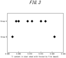
- the results illustrated in FIG. 3 indicate that when the Ti content in the steel sheet with forsterite film is at least 0.0039 % and at most 0.0200 %, the steel sheet tends to belong to group A.
- model transformer iron loss WT 17/50 transformer iron loss when excited at 50 Hz to 1.7 T
- the building factor F17 of the model transformer was then calculated as the model transformer iron loss WT 17/50 divided by the sample iron loss W 17/50 (WT 17/50 /W 17/50 ).
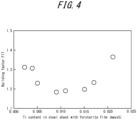
- the relationship between the building factor F17 and the Ti content in the steel sheet with forsterite film is illustrated in FIG. 4 .
- the results illustrated in FIG. 4 indicate that when the Ti content in the steel sheet with forsterite film is less than 0.0050 %, the building factor F17 is high even when the sheet belongs to group A.
- the inventors found that the building factor is low and good when the Ti content in the steel sheet with forsterite film is from 0.0050 % to 0.0200 %. This essentially means that it is good for a certain amount of Ti to be present in the forsterite film.
- the yoke and legs of the transformer have a certain width, and therefore the magnetic path differs in distance between the inside and the outside, like a track in athletics. Therefore, during excitation, the magnetic flux tends to be biased toward the inner side where the magnetic path is short. Even when the entire steel sheet is excited to 1.7 T, the magnetic flux density on the inner side exceeds that. Therefore, it may be that the more favorable the high magnetic field properties, the better the transformer properties such as the building factor. When Co is solute in iron, it is expected that the saturation magnetic flux density of the iron increases and high magnetic field properties improve, and this may be why the building factor improved. However, through Experiments 1 and 2, there were two cases where the building factor was not good, even when Co was added.
- the first case was when the ratio of the hysteresis loss Wh 17 to the iron loss W 17/50 when excited at 1.7 T, that is, R17, and the ratio of the hysteresis loss Wh 19 to the iron loss W 19/50 when excited at 1.9 T, that is, R19, did not satisfy the relationship 0.30 ⁇ R17 ⁇ R19. Detailed investigation revealed that R17 was less than 0.30 in the majority of cases. Hysteresis loss is highly correlated with B 8 and the same B 8 is not expected to vary significantly, and therefore the above is considered a case of extremely large eddy current loss.
- the second case was when the Ti content in the steel sheet with forsterite film was less than 0.0050 mass% or more than 0.0200 mass%.
- the presence of a certain amount of Ti in the forsterite film may improve film properties.
- an increase in film tension may refine the magnetic domain and decrease eddy current losses.
- the eddy current loss ratio is lowered, contrary to the case of R17 and R19 above, and therefore the building factor may be decreased.
- JP 2021-509149 A A production technique for a grain-oriented electrical steel sheet containing Co is described in JP 2021-509149 A .
- the literature mentions a technique to improve the magnetic properties of the electrical steel sheet itself, which is completely different from the present disclosure, which decreases the building factor by combination with a technology to include Ti in the forsterite film.
- a grain-oriented electrical steel sheet having magnetic properties that can sufficiently decrease the building factor can be provided.
- Si is an element necessary for increasing the specific resistance of steel and decreasing iron loss. Further, Si is an element necessary for forming forsterite film in the steel sheet according to the present disclosure. However, Si content of less than 1.50 % is ineffective, and the Si content exceeding 8.00 % degrades steel workability and makes rolling difficult. Accordingly, the Si content is limited to 1.50 % to 8.00 %.
- the Si content is preferably 2.50 % or more.
- the Si content is preferably 4.50 % or less.
- Mn is an element necessary for good hot workability. However, Mn content of less than 0.02 % is ineffective, and the Mn content exceeding 1.00 % decreases product sheet magnetic flux density. The Mn content is therefore from 0.02 % to 1.00 %.
- the Mn content is preferably 0.04 % or more.
- the Mn content is preferably 0.20 % or less.
- Co content be in the range from 0.005 % to 0.050 %.
- the Co content is preferably 0.006% or more.
- the Co content is more preferably 0.008 % or more.
- the Co content is preferably 0.020 % or less.
- the Co content is more preferably 0.015 % or less.
- the base steel sheet of the grain-oriented electrical steel sheet may contain C (for example, 0.020 % to 0.100 %), may contain Al (for example, 0.002 % to 0.040 %), and may contain N (for example, 0.002 % to 0.015 %). Further, the base steel sheet may optionally contain S (for example, 0.020 % or less) and/or Se (for example, 0.040 % or less). In addition to the above components, the base steel sheet of the grain-oriented electrical steel sheet may contain the components (elements) described below as required.
- the base steel sheet may contain one or more selected from the group consisting of Sn: (more than 0 %) 0.500 % or less, Cr: (more than 0 %) 0.500 % or less, Cu: (more than 0 %) 0.50 % or less, Ni: (more than 0 %) 0.50 % or less, Bi: (more than 0 %) 0.500 % or less, P: (more than 0 %) 0.500 % or less, Sb (more than 0 %) 0.500 % or less, Mo: (more than 0 %) 0.500 % or less, B: (more than 0 ppm) 25.0 ppm or less, Nb: (more than 0 %) 0.020 % or less, V: (more than 0 %) 0.020 % or less, As: (more than 0 %) 0.0200 % or less, Zn: (more than 0 %) 0.020 % or less, Pb: (more than 0 %) (more than 0 %)
- each of the above elements may be contained in the base steel sheet in a range up to the upper limit described above to further improve magnetic properties.
- the amount of each element added (content) exceeds the above upper limit, the development of secondary recrystallized grains may be suppressed and magnetic properties may deteriorate.
- each element is preferably contained in the following range.
- Sn 0.005 % or more, Cr: 0.005 % or more, Cu: 0.01 % or more, Ni: 0.01 % or more, Bi: 0.005 % or more, P: 0.005 % or more, Sb: 0.005 % or more, Mo: 0.005 % or more, B: 0.1 ppm or more, Nb: 0.001 % or more, V: 0.001 % or more, As: 0.0010 % or more, Zn: 0.001 % or more, Pb: 0.0001 % or more, W: 0.0010 % or more, Ga: 0.0001 % or more, and Ge: 0.0001 % or more.
- the balance other than the components (elements) mentioned above is Fe and inevitable impurity.
- the chemical composition described above is the chemical composition in the base steel sheet, that is, without considering the base film, which is mainly composed of forsterite.
- Ti content in the steel sheet with the base film mainly composed of forsterite that is, the Ti content in the base steel sheet and the base film as a whole, is limited to 0.0050 % to 0.0200 % for the reasons mentioned above.
- the Ti content in the base steel sheet and the base film as a whole is preferably 0.0060 % or more.
- the Ti content is preferably 0.0150 % or less.
- the term "mainly composed” with respect to the base film refers to the component having the greatest mass among the components of the base film.
- the hysteresis loss can be calculated by multiplying the energy loss of the iron core in one cycle of the hysteresis loop by 50, which is the excitation frequency.
- the following describes a method of producing the grain-oriented electrical steel sheet according to the present disclosure.
- the method of production may use a typical method for producing an electrical steel sheet.
- molten steel prepared to have defined components may be made into a slab by typical ingot casting or continuous casting, or made into a thin slab or thinner cast steel having a thickness of 100 mm or less by direct casting.
- Molten steel may be produced by either a blast furnace or an electric furnace steelmaking process.
- the various components that may be contained in the base steel sheet are difficult to add during the process, and therefore adding them at the molten steel stage is preferred.
- the slab may be heated and hot rolled by a typical method or hot rolled directly after casting without heating.
- a chemical composition containing a small amount of inhibitor components does not require high-temperature annealing for dissolving the inhibitor, and therefore a low temperature of 1300 °C or less is effective for cost-reduction purposes.
- the temperature is preferably 1250 °C or less.
- hot-rolled sheet annealing may be carried out as required.
- the temperature of hot-rolled sheet annealing is preferably about 950 °C to 1150 °C. When the temperature is 950 °C or more, residual un-recrystallized portions can be sufficiently suppressed, and when the temperature is 1150 °C or less, excessive coarsening of grain size after annealing can be suppressed and the subsequent primary recrystallized texture can be made more favorable.
- the temperature of hot-rolled sheet annealing is preferably 1000 °C or more.
- the temperature of hot-rolled sheet annealing is preferably 1100 °C or less.
- the steel sheet after the hot rolling or hot-rolled sheet annealing is subjected to cold rolling once, or twice or more with intermediate annealing carried out therebetween, to obtain a cold-rolled sheet having a final sheet thickness.
- the annealing temperature for intermediate annealing is preferably in a range from 900 °C to 1200 °C.
- the temperature is 900 °C or more, the recrystallized grain becoming too fine after intermediate annealing can be well suppressed, and further, a decrease in magnetic properties of the product sheet due to a decrease in Goss nuclei in the primary recrystallized texture can be well suppressed.
- the temperature is 1200 °C or less, as with hot-rolled sheet annealing, excessive coarsening of crystal grains can be suppressed and the primary recrystallized texture of the uniformly-sized grains can be made better.
- the cold-rolled sheet having a final sheet thickness is then subjected to primary recrystallization annealing that also serves as decarburization annealing.
- the annealing temperature for this primary recrystallization annealing is, when accompanied by decarburization annealing and from the viewpoint of allowing the decarburization reaction to proceed rapidly, preferably in a range from 800 °C to 900 °C, and the atmosphere is preferably a wet atmosphere.
- Ti may be made to be present in the forsterite film in other ways.
- secondary recrystallization annealing (purification annealing) is carried out.
- This purification annealing is preferably carried out at 800 °C or more for the development of secondary recrystallization, and from the purification point of view, the temperature is preferably raised to a holding temperature of 1100 °C or more.
- the holding temperature is more preferably 1180 °C or more.
- the longer the hold time the more purification progresses, but shape degradation may occur due to high-temperature creep, and therefore the hold time is preferably at least 3 h and at most 15 h.
- water washing, brushing, or pickling is preferably carried out to remove adhered annealing separator.
- an N 2 atmosphere up to a first intermediate temperature for example, a temperature selected from the range from 600 °C to 800 °C
- a mixed N 2 and H 2 atmosphere from the first intermediate temperature to a second intermediate temperature for example, a temperature selected from the range from 1050 °C to 1150 °C
- an H 2 atmosphere from the second intermediate temperature to the holding temperature for example, a temperature selected from the range from 1050 °C to 1150 °C
- flattening annealing is carried out for shape adjustment, which is effective for iron loss reduction.
- applying an insulating coating to the steel sheet surface before or after the flattening annealing is effective for reducing iron loss.
- the insulating coating a film that can impart tension to the steel sheet to reduce iron loss is preferable.
- a method of tension film coating application through a binder, or coating by depositing an inorganic substance onto the steel sheet surface layer by physical vapor deposition or chemical vapor deposition is preferable, as these methods have excellent coating adhesion and a considerable iron loss reduction effect.
- Steel slab A - C 0.070 %, Si: 3.55 %, Mn: 0.07 %, Al: 0.0080 %, N: 0.0050 %, Co: 0.012 %, Mo: 0.026 %, Ti: 0.025 %, with the balance being Fe and inevitable impurity.
- Steel slab B - C 0.072 %, Si: 3.51 %, Mn: 0.07 %, Al: 0.0080 %, N: 0.0047 %, Co: 0.011 %, Mo: 0.025 %, Ti: 0.0025 %, with the balance being Fe and inevitable impurity.
- Each of the steel slabs A to D described above was produced by continuous casting, and after slab heating to soak at 1200 °C for 40 min, the slabs were hot rolled to a thickness of 2.2 mm. Hot-rolled sheet annealing was then carried out at 1000 °C for 60 s in an N 2 atmosphere. Next, cold rolling was carried out to a thickness of 0.23 mm, followed by decarburization annealing at 850 °C for 90 s in a wet atmosphere of 60 % H 2 - 40 % N 2 with a dew point of 60 °C.
- an annealing separator consisting mainly of MgO (MgO: 97 mass%) was applied, and purification annealing was carried out by holding at 1100 °C for 25 h, then holding at 1200 °C for 10 h.
- an N 2 atmosphere was used from room temperature to 700 °C
- an atmosphere in which the mixing ratio of N 2 and H 2 was varied was used from 700 °C to 1100 °C
- an H 2 atmosphere was used from 1100 °C (start of holding) to 1200 °C (end of holding).
- an Ar atmosphere was used during cooling.
- the Ti content (the total Ti content of the base steel sheet and the base film) of the obtained samples was measured according to the method specified in JIS G1223. The results are listed in Table 1.
- a three-phase three-leg model transformer simulating a transformer was fabricated having an external shape of 500 mm square and a sheet width of 100 mm for each leg and each yoke, and model transformer iron loss WT 17/50 (transformer iron loss when excited at 50 Hz to 1.7 T) was measured.
- the number of stacked sheets of each sample was 50, with two sheets stacked alternately.
- the building factor F17 of the model transformer was then calculated as the model transformer iron loss WT 17/50 divided by the sample iron loss W 17/50 (WT 17/50 /W 17/50 ). The results are listed in Table 1.
- cold rolling was carried out to a thickness of 0.23 mm, followed by decarburization annealing at 825 °C for 150 s in a wet atmosphere of 40 % H 2 - 60% N 2 with a dew point of 45 °C.
Landscapes
- Chemical & Material Sciences (AREA)
- Engineering & Computer Science (AREA)
- Metallurgy (AREA)
- Organic Chemistry (AREA)
- Materials Engineering (AREA)
- Mechanical Engineering (AREA)
- Physics & Mathematics (AREA)
- Thermal Sciences (AREA)
- Crystallography & Structural Chemistry (AREA)
- Electromagnetism (AREA)
- Manufacturing & Machinery (AREA)
- Dispersion Chemistry (AREA)
- Power Engineering (AREA)
- Chemical Kinetics & Catalysis (AREA)
- General Chemical & Material Sciences (AREA)
- Manufacturing Of Steel Electrode Plates (AREA)
- Soft Magnetic Materials (AREA)
Abstract
Description
- The present disclosure relates to a grain-oriented electrical steel sheet advantageously utilized for an iron core of a transformer.
- Grain-oriented electrical steel sheets are soft magnetic materials used as iron core materials for transformers, and have crystal microstructures in which the <001> orientation, which is an easy magnetization axis of iron, is highly accorded with the rolling direction of the steel sheets. Such texture is formed through a phenomenon called secondary recrystallization where crystal grains with {110}<001> orientation, also known as Goss orientation, grow preferentially to large sizes during purification annealing in the process of producing a grain-oriented electrical steel sheet.
- A typical technique used for such a production process causes grains having Goss orientation to undergo secondary recrystallization during purification annealing using precipitates called inhibitors. For example, Patent Literature (PTL) 1 describes a method using AlN and MnS, PTL 2 describes a method using MnS and MnSe, and both of these methods have been put into industrial use.
- These methods using inhibitors are useful for stable growth of secondary recrystallized grains, but for the purpose of fine particle distribution of the inhibitors into the steel, slab heating at high temperatures of 1300 °C or more is necessary to dissolve the inhibitor components in solid solution.
- On the other hand, for a material containing no inhibitor components, a technique for developing crystal grains having Goss orientation through secondary recrystallization is described in PTL 3, for example. This technique eliminates impurities such as inhibitor components as much as possible and realizes grain boundary misorientation angle dependence of grain boundary energy possessed by crystal grain boundaries during primary recrystallization, thereby causing secondary recrystallization of grains having Goss orientation without using inhibitors. This effect is called the texture inhibition effect. This method does not require fine particle distribution of inhibitor into steel and therefore does not require high-temperature slab heating, which was previously essential, and is therefore a method that has significant advantages in terms of cost and maintenance.
- Grain-oriented electrical steel sheets, which are mainly used as iron cores of transformers, are required to have excellent magnetization properties, in particular low iron loss. To achieve this, it is important to highly align the secondary recrystallized grains in a steel sheet to the Goss orientation and to decrease impurities in the product sheet. Further, techniques have been developed for introducing non-uniformity to the steel sheet surfaces by physical means to subdivide magnetic domain width for less iron loss, namely, magnetic domain refining techniques. For example, PTL 4 proposes a technique of irradiating a steel sheet after final annealing with a laser to introduce high-dislocation density regions into a surface layer of the steel sheet, thereby narrowing magnetic domain widths and decreasing iron loss of the steel sheet. Further, PTL 5 proposes a technique of controlling magnetic domain widths by irradiation with an electron beam.
- The highly-aligned orientation after secondary recrystallization to the Goss orientation and the decrease in impurities in the product sheet result in lower hysteresis loss. In contrast, eddy current loss is mainly decreased when magnetic domain refining techniques are applied.
-
- PTL 1:
JP S40-15644 B2 - PTL 2:
JP S51-13469 B2 - PTL 3:
JP 2000-129356 A - PTL 4:
JP S57-2252 B2 - PTL 5:
JP H06-72266 B2 - As mentioned above, grain-oriented electrical steel sheets are mainly used as the iron cores of transformers. In general, there is a discrepancy between the iron loss value of a transformer iron core and the iron loss value of a grain-oriented electrical steel sheet that is a material of the iron core, and the iron loss is greater for the transformer iron core. The iron loss ratio of the two (the iron loss of the transformer iron core divided by the iron loss value of the material) is called the building factor. That is, even when the iron loss of the material is low, when the building factor is high, the iron loss of the transformer iron core is large, creating a problem of insufficient performance. In the carbon-neutral era, what needs to be decreased is the iron loss of the final product, the transformer. No matter how low the iron loss of the material is, it is meaningless when the building factor is high. The building factor affects not only transformer design but also material properties, and therefore there is a demand to lower the building factor as well as the iron loss of the material.
- That is, it would be helpful to provide a grain-oriented electrical steel sheet having magnetic properties that can sufficiently decrease the building factor.
- As a result of extensive studies, the inventors have discovered that a grain-oriented electrical steel sheet that can obtain a low building factor can be produced by controlling, within certain ranges, the Co content in a base steel sheet, on which a base film mainly composed of forsterite is formed, and the Ti content in the grain-oriented electrical steel sheet with the base film formed thereon.
- The following describes the experiments that successfully led to the present disclosure.
- Mainly in order to vary the Co content, steel slabs were produced by continuous casting, containing, in mass%, C: 0.050 % to 0.081 %, Si: 3.15 % to 3.31 %, Mn: 0.07 % to 0.10 %, Al: 0.020 % to 0.025 %, N: 0.0069 % to 0.0085 %, S: 0.0011 % to 0.0031 %, Sb: 0.025 % to 0. 036 %, Co: 0 % to 0.123 %, and Ti: 0.0080 % to 0.0090 %, with the balance being Fe and inevitable impurity. After slab heating and soaking at 1400 °C for 20 min, the slabs were hot rolled to a thickness of 2.4 mm. Subsequently, hot-rolled sheet annealing was carried out at 1000 °C for 30 s in an N2 atmosphere. Next, cold rolling was carried out to a thickness of 1.5 mm, followed by intermediate annealing at 1000 °C for 100 s in a 25 % H2 - 75 % N2 atmosphere. Subsequently, cold rolling was carried out to a thickness of 0.23 mm, followed by decarburization annealing at 850 °C for 150 s in a wet atmosphere of 50 % H2 - 50 % N2 with a dew point of 50 °C. Next, after the decarburization annealing, to the surface of each base steel sheet, an annealing separator consisting mainly of MgO was applied, and purification annealing was carried out by holding at 1200 °C for 10 h. At this time, the heating rate to 1200 °C was 20 °C/h. Further, during the heating process, an N2 atmosphere was used from room temperature to 700 °C, an atmosphere in which the mixing ratio of N2 and H2 was varied was used from 700 °C to 1100 °C, and an H2 atmosphere was used from 1100 °C to 1200 °C. Further, an H2 atmosphere was used during the hold time, and an Ar atmosphere was used during cooling. In this way, samples were obtained where a base film consisting mainly of forsterite (hereinafter also referred to as forsterite film) was formed on the surface of each base steel sheet.
- For the samples thus obtained, the iron loss W17/50 (iron loss when excited at 50 Hz up to 1.7 T) and W19/50 (iron loss when excited at 50 Hz up to 1.9 T), hysteresis loss Wh17 (hysteresis loss when excited up to 1.7 T) and Wh19 (hysteresis loss when excited up to 1.9 T) were measured by the method specified in Japanese Industrial Standard JIS C2550-1.
- Further, to measure the amount of Co in each base steel sheet, a portion of the obtained sample was immersed in a 10 % hydrochloric acid aqueous solution at 80 °C for 180 s to remove the forsterite film, and the amount of Co was measured by the method specified in JIS G1222.
- Then, from each of the obtained samples, a three-phase three-leg model transformer simulating a transformer was fabricated having an external shape of 500 mm square and a sheet width of 100 mm for each leg and each yoke, and model transformer iron loss WT17/50 (transformer iron loss when excited at 50 Hz to 1.7 T) was measured. The number of stacked sheets of each sample was 50, with two sheets stacked alternately. The building factor F17 of the model transformer was then calculated as the model transformer iron loss WT17/50 divided by the sample iron loss W17/50 (WT17/50/W17/50). The relationship between the building factor F17 and the amount of Co in the base steel sheet is illustrated in
FIG. 1 . - The results illustrated in
FIG. 1 indicate no clear correlation between the building factor F17 and Co content. However, it can be read fromFIG. 1 that the building factor F17 is divided into good values of 1.25 or less and high values of 1.30 or more. - The relationship between iron loss and hysteresis loss of the samples was examined to see whether this difference could be explained. As a result, when R17 is the ratio of hysteresis loss Wh17 to iron loss W17/50 when excited at 1.7 T, and R19 is the ratio of hysteresis loss Wh19 to iron loss W19/50 when excited at 1.9 T, the inventors found that there are two groups, group A having the relationship 0.30 ≤ R17 ≤ R19, and the other group B.
FIG. 2 is the result of extracting and redrawing only the group A of the data inFIG. 1 . - The results illustrated in
FIG. 2 indicate that results belonging to group A, that is, having the relationship 0.30 ≤ R17 ≤ R19, in a Co content range from 0.005 % to 0.050 %, indicate a good building factor of 1.25 or less. - Steel slabs were produced by continuous casting, containing, in mass%, C: 0.037 %, Si: 3.05 %, Mn: 0.18 %, Al: 0.009 %, N: 0.0036 %, Se: 0.007 %, Sn: 0.062 %, and Co: 0.0080 %, with the balance being Fe and inevitable impurity. After slab heating and soaking at 1300 °C for 30 min, the slabs were hot rolled to a thickness of 2.2 mm. Subsequently, hot-rolled sheet annealing was carried out at 1100 °C for 30 s in an N2 atmosphere. Next, cold rolling was carried out to a thickness of 0.23 mm, followed by decarburization annealing at 840 °C for 120 s in a wet atmosphere of 40 % H2 - 60 % N2 with a dew point of 40 °C. Next, after the decarburization annealing, to the surface of each base steel sheet, an annealing separator containing TiO2 in various amounts ranging from 0 to 15 parts by mass relative to MgO was applied, and purification annealing was carried out by holding at 1220 °C for 5 h. At this time, the heating rate to 1220 °C was 15 °C/h. Further, during the heating process, an N2 atmosphere was used from room temperature to 700 °C, an atmosphere in which the mixing ratio of N2 and H2 was varied was used from 700 °C to 1100 °C, and an H2 atmosphere was used from 1100 °C to 1220 °C. Further, an H2 atmosphere was used during the hold time, and an Ar atmosphere was used during cooling. In this way, samples were obtained where a base film consisting mainly of forsterite (hereinafter also referred to as forsterite film) was formed on the surface of each base steel sheet.
- For the samples thus obtained, the iron losses W17/50 and W19/50 and hysteresis losses Wh17 and Wh19 were measured as in
Experiment 1, using the method specified in JIS C2550-1. - Further, the Ti content in each steel sheet with the forsterite film was measured by the method specified in JIS G1223.
- Further, to measure the amount of Co in each base steel sheet, a portion of the obtained sample was immersed in a 10 % hydrochloric acid aqueous solution at 80 °C for 180 s to remove the forsterite film, and the amount of Co was measured by the method specified in JIS G1222. As a result, the Co content was 0.0080 %, which was equivalent to that of the steel slab.
- Further, as in
Experiment 1, when R17 is the ratio of hysteresis loss Wh17 to iron loss W17/50 when excited at 1.7 T, and R19 is the ratio of hysteresis loss Wh19 to iron loss W19/50 when excited at 1.9 T, the results were divided into two groups, group A having the relationship 0.30 ≤ R17 ≤ R19, and the other group B. The relationship between the Ti content in steel sheets with forsterite film and belonging to group A or group B is illustrated inFIG. 3 . - The results illustrated in
FIG. 3 indicate that when the Ti content in the steel sheet with forsterite film is at least 0.0039 % and at most 0.0200 %, the steel sheet tends to belong to group A. - Further, as in
Experiment 1, three-phase three-leg model transformers were fabricated, each having an external shape of 500 mm square and a sheet width of 100 mm for each leg and each yoke, and model transformer iron loss WT17/50 (transformer iron loss when excited at 50 Hz to 1.7 T) was measured. The building factor F17 of the model transformer was then calculated as the model transformer iron loss WT17/50 divided by the sample iron loss W17/50 (WT17/50/W17/50). The relationship between the building factor F17 and the Ti content in the steel sheet with forsterite film is illustrated inFIG. 4 . - The results illustrated in
FIG. 4 indicate that when the Ti content in the steel sheet with forsterite film is less than 0.0050 %, the building factor F17 is high even when the sheet belongs to group A. In summary, the inventors found that the building factor is low and good when the Ti content in the steel sheet with forsterite film is from 0.0050 % to 0.0200 %. This essentially means that it is good for a certain amount of Ti to be present in the forsterite film. - The mechanism by which the building factor of the model transformer becomes better depending on the Co content in the base steel sheet and the Ti content in the steel sheet with a base film that is mainly forsterite, as described above, is not clear, but the inventors consider the following to be possible.
- The yoke and legs of the transformer have a certain width, and therefore the magnetic path differs in distance between the inside and the outside, like a track in athletics. Therefore, during excitation, the magnetic flux tends to be biased toward the inner side where the magnetic path is short. Even when the entire steel sheet is excited to 1.7 T, the magnetic flux density on the inner side exceeds that. Therefore, it may be that the more favorable the high magnetic field properties, the better the transformer properties such as the building factor. When Co is solute in iron, it is expected that the saturation magnetic flux density of the iron increases and high magnetic field properties improve, and this may be why the building factor improved. However, through
Experiments 1 and 2, there were two cases where the building factor was not good, even when Co was added. - The first case was when the ratio of the hysteresis loss Wh17 to the iron loss W17/50 when excited at 1.7 T, that is, R17, and the ratio of the hysteresis loss Wh19 to the iron loss W19/50 when excited at 1.9 T, that is, R19, did not satisfy the relationship 0.30 ≤ R17 ≤ R19. Detailed investigation revealed that R17 was less than 0.30 in the majority of cases. Hysteresis loss is highly correlated with B8 and the same B8 is not expected to vary significantly, and therefore the above is considered a case of extremely large eddy current loss. In a transformer, even when excited with a sinusoidal waveform, a high-harmonic component is superimposed and the waveform is distorted, which may increase eddy current loss, which is highly frequency-dependent. Therefore, a high eddy current loss ratio may increase the building factor.
- The second case was when the Ti content in the steel sheet with forsterite film was less than 0.0050 mass% or more than 0.0200 mass%. Although only a hypothesis, the presence of a certain amount of Ti in the forsterite film may improve film properties. For example, an increase in film tension may refine the magnetic domain and decrease eddy current losses. In such a case, the eddy current loss ratio is lowered, contrary to the case of R17 and R19 above, and therefore the building factor may be decreased.
- A production technique for a grain-oriented electrical steel sheet containing Co is described in
JP 2021-509149 A - The present disclosure is based on the above discoveries. Primary features of the present disclosure are as follows.
- 1. A grain-oriented electrical steel sheet comprising a base steel sheet containing Si: 1.50 mass% to 8.00 mass%, Mn: 0.02 mass% to 1.00 mass%, and Co: 0.005 mass% to 0.050 mass%, and a base film mainly composed of forsterite, formed on the surface of the base steel sheet, wherein
- Ti content in the base steel sheet and the base film as a whole is 0.0050 mass% to 0.0200 mass%, and
- the following expression (1) is satisfied, where R17 is the ratio of hysteresis loss Wh17 to iron loss W17/50 when excited at 1.7 T and R19 is the ratio of hysteresis loss Wh19 to iron loss W19/50 when excited at 1.9 T,

- 2. The grain-oriented electrical steel sheet according to 1, above, wherein Ti content in the base steel sheet is 0.0030 mass% or less.
- 3. The grain-oriented electrical steel sheet according to 1 or 2, above, further comprising an insulating coating on the surface of the base film.
- 4. The grain-oriented electrical steel sheet according to any one of 1 to 3, above, wherein the base steel sheet further contains one or more selected from the group consisting of Sn: 0.500 mass% or less, Cr: 0.500 mass% or less, Cu: 0.50 mass% or less, Ni: 0.50 mass% or less, Bi: 0.500 mass% or less, P: 0.500 mass% or less, Sb: 0.500 mass% or less, Mo: 0.500 mass% or less, B: 25.0 mass ppm or less, Nb: 0.020 mass% or less, V: 0.020 mass% or less, As: 0.0200 mass% or less, Zn: 0.020 mass% or less, Pb: 0.0100 mass% or less, W: 0.0100 mass% or less, Ga: 0.0050 mass% or less, and Ge: 0.0050 mass% or less.
- According to the present disclosure, a grain-oriented electrical steel sheet having magnetic properties that can sufficiently decrease the building factor can be provided.
- In the accompanying drawings:
-
FIG. 1 is a graph illustrating a relationship between Co content of base steel sheets and building factor F17, with respect toExperiment 1; -
FIG. 2 is a graph illustrating the relationship between Co content of base steel sheets and building factor F17 (where only group A is extracted), with respect toExperiment 1; -
FIG. 3 is a graph illustrating a relationship between Ti content of steel sheets with forsterite film and belonging to group A or group B, with respect to Experiment 2; and -
FIG. 4 is a graph illustrating a relationship between Ti content of steel sheets with forsterite film and building factor F17, with respect to Experiment 2. - Reasons for limitations on the primary features of the present disclosure are explained below. First, the amount of each element (chemical composition) in the base steel sheet of the grain-oriented electrical steel sheet is explained. Hereinafter, "%" and "ppm" designations for chemical composition refer to "mass%" and "mass ppm," respectively, unless otherwise noted.
- Si is an element necessary for increasing the specific resistance of steel and decreasing iron loss. Further, Si is an element necessary for forming forsterite film in the steel sheet according to the present disclosure. However, Si content of less than 1.50 % is ineffective, and the Si content exceeding 8.00 % degrades steel workability and makes rolling difficult. Accordingly, the Si content is limited to 1.50 % to 8.00 %. The Si content is preferably 2.50 % or more. The Si content is preferably 4.50 % or less.
- Mn is an element necessary for good hot workability. However, Mn content of less than 0.02 % is ineffective, and the Mn content exceeding 1.00 % decreases product sheet magnetic flux density. The Mn content is therefore from 0.02 % to 1.00 %. The Mn content is preferably 0.04 % or more. The Mn content is preferably 0.20 % or less.
- For the reasons mentioned above, it is essential that Co content be in the range from 0.005 % to 0.050 %. The Co content is preferably 0.006% or more. The Co content is more preferably 0.008 % or more. Further, the Co content is preferably 0.020 % or less. The Co content is more preferably 0.015 % or less.
- In addition to the basic components (Si, Mn, and Co) described above, the base steel sheet of the grain-oriented electrical steel sheet may contain C (for example, 0.020 % to 0.100 %), may contain Al (for example, 0.002 % to 0.040 %), and may contain N (for example, 0.002 % to 0.015 %). Further, the base steel sheet may optionally contain S (for example, 0.020 % or less) and/or Se (for example, 0.040 % or less). In addition to the above components, the base steel sheet of the grain-oriented electrical steel sheet may contain the components (elements) described below as required.
- Specifically, for the purpose of improving magnetic properties, the base steel sheet may contain one or more selected from the group consisting of Sn: (more than 0 %) 0.500 % or less, Cr: (more than 0 %) 0.500 % or less, Cu: (more than 0 %) 0.50 % or less, Ni: (more than 0 %) 0.50 % or less, Bi: (more than 0 %) 0.500 % or less, P: (more than 0 %) 0.500 % or less, Sb (more than 0 %) 0.500 % or less, Mo: (more than 0 %) 0.500 % or less, B: (more than 0 ppm) 25.0 ppm or less, Nb: (more than 0 %) 0.020 % or less, V: (more than 0 %) 0.020 % or less, As: (more than 0 %) 0.0200 % or less, Zn: (more than 0 %) 0.020 % or less, Pb: (more than 0 %) 0.0100 % or less, W: (more than 0 %) 0.0100 % or less, Ga: (more than 0 %) 0.0050 % or less, and Ge: (more than 0 %) 0.0050 % or less.
- That is, each of the above elements may be contained in the base steel sheet in a range up to the upper limit described above to further improve magnetic properties. When the amount of each element added (content) exceeds the above upper limit, the development of secondary recrystallized grains may be suppressed and magnetic properties may deteriorate. Although there is no particular need to limit a lower limit of each element, each element is preferably contained in the following range.
- Sn: 0.005 % or more, Cr: 0.005 % or more, Cu: 0.01 % or more, Ni: 0.01 % or more, Bi: 0.005 % or more, P: 0.005 % or more, Sb: 0.005 % or more, Mo: 0.005 % or more, B: 0.1 ppm or more, Nb: 0.001 % or more, V: 0.001 % or more, As: 0.0010 % or more, Zn: 0.001 % or more, Pb: 0.0001 % or more, W: 0.0010 % or more, Ga: 0.0001 % or more, and Ge: 0.0001 % or more.
- In the base steel sheet, the balance other than the components (elements) mentioned above is Fe and inevitable impurity.
- The chemical composition described above is the chemical composition in the base steel sheet, that is, without considering the base film, which is mainly composed of forsterite. Further, according to the present disclosure, Ti content in the steel sheet with the base film mainly composed of forsterite, that is, the Ti content in the base steel sheet and the base film as a whole, is limited to 0.0050 % to 0.0200 % for the reasons mentioned above. The Ti content in the base steel sheet and the base film as a whole is preferably 0.0060 % or more. The Ti content is preferably 0.0150 % or less.
- The term "mainly composed" with respect to the base film refers to the component having the greatest mass among the components of the base film.
- Here, in limiting the Ti content in the steel sheet with the base film to 0.0050 % to 0.0200 %, the Ti content in the base steel sheet is preferably 0.0030% or less. When the Ti content in the base steel sheet is 0.0030 % or less, significant degradation of iron loss due to the formation of Ti precipitates in steel can be suppressed. On the other hand, the Ti content in the steel sheet with the base film is 0.0050 % or more. This is because, as mentioned above, a certain amount of Ti in the forsterite film may improve film properties and decrease eddy current loss, but when the Ti content is less than 0.0050 %, the effect is estimated to be poor.
- Further, as mentioned above, the present disclosure requires limiting the range of a set of parameters calculated from hysteresis loss and iron loss of the product steel sheet. That is, the ratio R17 (=Wh17/W17/50) of hysteresis loss Wh17 to iron loss W17/50 when excited at 1.7 T and the ratio R19 (=Wh19/W19/50) of hysteresis loss Wh19 to iron loss W19/50 when excited at 1.9 T need to satisfy the relationship 0.30 ≤ R17 ≤ R19. These values can be measured by the method specified in JIS C2550-1. In order to match the hysteresis loss with the iron loss at 50 Hz, the hysteresis loss can be calculated by multiplying the energy loss of the iron core in one cycle of the hysteresis loop by 50, which is the excitation frequency.
- The following describes a method of producing the grain-oriented electrical steel sheet according to the present disclosure. The method of production may use a typical method for producing an electrical steel sheet. For example, molten steel prepared to have defined components may be made into a slab by typical ingot casting or continuous casting, or made into a thin slab or thinner cast steel having a thickness of 100 mm or less by direct casting. Molten steel may be produced by either a blast furnace or an electric furnace steelmaking process. The various components that may be contained in the base steel sheet are difficult to add during the process, and therefore adding them at the molten steel stage is preferred. The slab may be heated and hot rolled by a typical method or hot rolled directly after casting without heating. When heating, a chemical composition containing a small amount of inhibitor components does not require high-temperature annealing for dissolving the inhibitor, and therefore a low temperature of 1300 °C or less is effective for cost-reduction purposes. When heating, the temperature is preferably 1250 °C or less.
- Subsequently, hot-rolled sheet annealing may be carried out as required. The temperature of hot-rolled sheet annealing is preferably about 950 °C to 1150 °C. When the temperature is 950 °C or more, residual un-recrystallized portions can be sufficiently suppressed, and when the temperature is 1150 °C or less, excessive coarsening of grain size after annealing can be suppressed and the subsequent primary recrystallized texture can be made more favorable. The temperature of hot-rolled sheet annealing is preferably 1000 °C or more. The temperature of hot-rolled sheet annealing is preferably 1100 °C or less.
- The steel sheet after the hot rolling or hot-rolled sheet annealing is subjected to cold rolling once, or twice or more with intermediate annealing carried out therebetween, to obtain a cold-rolled sheet having a final sheet thickness. The annealing temperature for intermediate annealing is preferably in a range from 900 °C to 1200 °C. When the temperature is 900 °C or more, the recrystallized grain becoming too fine after intermediate annealing can be well suppressed, and further, a decrease in magnetic properties of the product sheet due to a decrease in Goss nuclei in the primary recrystallized texture can be well suppressed. On the other hand, when the temperature is 1200 °C or less, as with hot-rolled sheet annealing, excessive coarsening of crystal grains can be suppressed and the primary recrystallized texture of the uniformly-sized grains can be made better.
- The cold-rolled sheet having a final sheet thickness is then subjected to primary recrystallization annealing that also serves as decarburization annealing. The annealing temperature for this primary recrystallization annealing is, when accompanied by decarburization annealing and from the viewpoint of allowing the decarburization reaction to proceed rapidly, preferably in a range from 800 °C to 900 °C, and the atmosphere is preferably a wet atmosphere.
- Subsequently, an annealing separator mainly composed of MgO is applied, followed by purification annealing to develop a secondary recrystallized texture and form a forsterite film. Here, mainly composed of MgO means that MgO content is 75 mass% or more.
- Further, the addition of a Ti compound to the annealing separator and the introduction of an N2 atmosphere during purification annealing, as described below, effectively allow Ti to be present in the forsterite film. However, Ti may be made to be present in the forsterite film in other ways.
- Subsequently, secondary recrystallization annealing (purification annealing) is carried out. This purification annealing is preferably carried out at 800 °C or more for the development of secondary recrystallization, and from the purification point of view, the temperature is preferably raised to a holding temperature of 1100 °C or more. The holding temperature is more preferably 1180 °C or more. Here, the longer the hold time, the more purification progresses, but shape degradation may occur due to high-temperature creep, and therefore the hold time is preferably at least 3 h and at most 15 h. After the purification annealing, water washing, brushing, or pickling is preferably carried out to remove adhered annealing separator. Further, from the viewpoint of obtaining desired iron loss properties, in the heating process of the purification annealing, it is preferable to use an N2 atmosphere up to a first intermediate temperature (for example, a temperature selected from the range from 600 °C to 800 °C), a mixed N2 and H2 atmosphere from the first intermediate temperature to a second intermediate temperature (for example, a temperature selected from the range from 1050 °C to 1150 °C), and an H2 atmosphere from the second intermediate temperature to the holding temperature.
- Subsequently, flattening annealing is carried out for shape adjustment, which is effective for iron loss reduction. In the case of using the steel sheet in a stack, applying an insulating coating to the steel sheet surface before or after the flattening annealing is effective for reducing iron loss. As the insulating coating, a film that can impart tension to the steel sheet to reduce iron loss is preferable. A method of tension film coating application through a binder, or coating by depositing an inorganic substance onto the steel sheet surface layer by physical vapor deposition or chemical vapor deposition is preferable, as these methods have excellent coating adhesion and a considerable iron loss reduction effect.
- The present disclosure is described in detail below by reference to examples. However, the present disclosure is not limited to these examples.
- Steel slab A - C: 0.070 %, Si: 3.55 %, Mn: 0.07 %, Al: 0.0080 %, N: 0.0050 %, Co: 0.012 %, Mo: 0.026 %, Ti: 0.025 %, with the balance being Fe and inevitable impurity.
- Steel slab B - C: 0.072 %, Si: 3.51 %, Mn: 0.07 %, Al: 0.0080 %, N: 0.0047 %, Co: 0.011 %, Mo: 0.025 %, Ti: 0.0025 %, with the balance being Fe and inevitable impurity.
- Steel slab C - C: 0.072 %, Si: 3.49 %, Mn: 0.07 %, Al: 0.0090 %, N: 0.0051 %, Co: 0.002 %, Mo: 0.025 %, Ti: 0.024 %, with the balance being Fe and inevitable impurity.
- Steel slab D - C: 0.068 %, Si: 3.48 %, Mn: 0.07 %, Al: 0.0090 %, N: 0.0050 %, Co: 0.008 %, Mo: 0.022 %, Ti: 0.0010 %, with the balance being Fe and inevitable impurity.
- Each of the steel slabs A to D described above was produced by continuous casting, and after slab heating to soak at 1200 °C for 40 min, the slabs were hot rolled to a thickness of 2.2 mm. Hot-rolled sheet annealing was then carried out at 1000 °C for 60 s in an N2 atmosphere. Next, cold rolling was carried out to a thickness of 0.23 mm, followed by decarburization annealing at 850 °C for 90 s in a wet atmosphere of 60 % H2 - 40 % N2 with a dew point of 60 °C.
- Next, after the decarburization annealing, to the surface of each base steel sheet, an annealing separator consisting mainly of MgO (MgO: 97 mass%) was applied, and purification annealing was carried out by holding at 1100 °C for 25 h, then holding at 1200 °C for 10 h. During the heating process, an N2 atmosphere was used from room temperature to 700 °C, an atmosphere in which the mixing ratio of N2 and H2 was varied was used from 700 °C to 1100 °C, and an H2 atmosphere was used from 1100 °C (start of holding) to 1200 °C (end of holding). Further, an Ar atmosphere was used during cooling.
- The Ti content (the total Ti content of the base steel sheet and the base film) of the obtained samples, that is, steel sheets with a mainly forsterite base film, was measured according to the method specified in JIS G1223. The results are listed in Table 1.
- On the base film of each of the above steel sheets, an insulating coating consisting mainly of magnesium phosphate and silica was applied and formed. For the samples thus obtained, the iron loss W17/50 (iron loss when excited at 50 Hz up to 1.7 T) and W19/50 (iron loss when excited at 50 Hz up to 1.9 T), and hysteresis loss Wh17 (hysteresis loss when excited up to 1.7 T) and Wh19 (hysteresis loss when excited up to 1.9 T) were measured according to the method specified in Japanese Industrial Standard JIS C2550-1. Wh17/W17/50 (that is, R17), and Wh19/W19/50 (that is, R19) are listed in Table 1.
- Further, to measure the Co content and Ti content in each base steel sheet, a portion of the obtained sample was immersed in a 10 % hydrochloric acid aqueous solution at 80 °C for 180 s to remove the base film, and the Co content and Ti content were measured by the methods specified in JIS G1222 and JIS G1223. The measurement results are listed in Table 1.
- Then, from each of the samples with the insulating coating, a three-phase three-leg model transformer simulating a transformer was fabricated having an external shape of 500 mm square and a sheet width of 100 mm for each leg and each yoke, and model transformer iron loss WT17/50 (transformer iron loss when excited at 50 Hz to 1.7 T) was measured. The number of stacked sheets of each sample was 50, with two sheets stacked alternately. The building factor F17 of the model transformer was then calculated as the model transformer iron loss WT17/50 divided by the sample iron loss W17/50 (WT17/50/W17/50). The results are listed in Table 1.
-
Table 1 No. Slab type Ti content in steel sheet with base film (%) Ti content in base steel sheet (%) Co content in base steel sheet (%) R17 R19 Building factor F17 Remarks 1 A 0.0180 0.0015 0.012 0.39 0.51 1.18 Example 2 B 0.0024 0.0020 0.011 0.28 0.40 1.41 Comparative Example 3 C 0.0190 0.0018 0.002 0.35 0.49 1.35 Comparative Example 4 D 0.0018 0.0015 0.008 0.34 0.50 1.32 Comparative Example - It is clear from Table 1 that good iron loss properties (building factor) were obtained for the sample according to the present disclosure (grain-oriented electrical steel sheet).
- Steel slabs containing the components listed in Table 2, with the balance being Fe and inevitable impurity, were prepared by continuous casting. Each steel slab was subjected to slab heating to soak at 1410 °C for 20 min, and hot rolled to obtain a hot-rolled sheet having a thickness of 2.4 mm. Hot-rolled sheet annealing was then carried out at 1100 °C for 20 s in an N2 atmosphere. Next, cold rolling was carried out to a thickness of 1.5 mm, followed by intermediate annealing at 900 °C for 100 s in a 25 % H2 - 75 % N2 atmosphere. Subsequently, cold rolling was carried out to a thickness of 0.23 mm, followed by decarburization annealing at 825 °C for 150 s in a wet atmosphere of 40 % H2 - 60% N2 with a dew point of 45 °C.
-
Table 2 No. Slab Type Si Mn Co C Al N S Se Other components mass% mass% mass% mass% mass% mass% mass% mass% mass% 5 E 3.26 0.52 0.005 0.041 0.033 0.0033 0.0023 - - 6 F 3.26 0.12 0.011 0.042 0.009 0.0081 - 0.005 - 7 G 2.22 0.18 0.045 0.056 0.011 0.0028 0.0009 - - 8 H 1.16 0.20 0.009 0.067 0.014 0.0049 0.0015 - - 9 I 5.25 0.24 0.011 0.027 0.018 0.0048 0.0017 0.016 - 10 J 3.02 0.01 0.017 0.038 0.012 0.0045 0.0018 - - 11 K 3.28 1.05 0.010 0.045 0.011 0.0047 0.0028 0.022 - 12 L 2.98 0.24 0.002 0.071 0.023 0.0026 0.0034 0.023 - 13 M 3.20 0.18 0.065 0.030 0.013 0.0078 0.0023 0.002 - 14 N 3.41 0.14 0.007 0.058 0.007 0.0033 0.0015 - Sn:0.350, Ni:0.23, Bi:0.006, V:0.002 15 O 3.00 0.22 0.016 0.047 0.018 0.0036 0.0010 0.007 Cr:0.012, As:0.0080, Ge:0.0040, P:0.010, Ni:0.02 16 P 3.09 0.20 0.018 0.025 0.030 0.0034 - - P:0.120, Sb:0.007, Nb:0.002, Cr:0.27 17 Q 3.41 0.22 0.015 0.080 0.014 0.0082 0.0011 - W:0.0020, Zn:0.007, Pb:0.0080, Ti:0.0100 18 R 3.39 0.21 0.010 0.076 0.030 0.0035 0.0033 0.007 Sn:0.009, B:21.2 ppm, Cu:0.35, Ga:0.0040 19 S 3.46 0.15 0.010 0.070 0.009 0.0038 0.0033 0.011 Cr:0.41, Bi:0.170, Pb:0.0004. Mo:0.250 20 T 3.21 0.11 0.010 0.033 0.008 0.0031 0.0028 - Cu:0.02, As:0.0015, Zn:0.012, W:0.0080 21 U 3.35 0.06 0.011 0.037 0.012 0.0072 0.0022 0.018 Sb:0.330, Ga:0.0003, Ge:0.0003, B:0.3 ppm 22 V 4.41 0.14 0.016 0.082 0.027 0.0078 0.0013 - Mo:0.008, Ti:0.0008, V:0.011, Nb:0.012 - Next, after the decarburization annealing, to the surface of each base steel sheet, an annealing separator consisting mainly of MgO (MgO: 88 mass%) was applied. For the annealing separator, TiO2 powder was put into warm water at 50 °C and stirred for 24 h, and 5 parts by mass of the resulting superhydrated TiO2 was added to the MgO powder.
- Further, purification annealing was carried out by holding at 1200 °C for 10 h. At this time, the heating rate to 1200 °C was 15 °C/h. Further, during the heating process, an N2 atmosphere was used from room temperature to 700 °C, an atmosphere in which the mixing ratio of N2 and H2 was varied was used from 700 °C to 1100 °C, and an H2 atmosphere was used from 1100 °C to 1200 °C. Further, an H2 atmosphere was used during the hold time, and an Ar atmosphere was used during cooling.
- The Ti content (the total Ti content of the base steel sheet and the base film) of the obtained samples, that is, steel sheets with a mainly forsterite base film, was measured according to the method specified in JIS G1223. The measurement results are listed in Table 3.
- On the base film of each of the above steel sheets, an insulating coating consisting mainly of magnesium phosphate and silica was applied and formed. For the samples thus obtained, the iron loss W17/50 (iron loss when excited at 50 Hz up to 1.7 T) and W19/50 (iron loss when excited at 50 Hz up to 1.9 T), and hysteresis loss Wh17 (hysteresis loss when excited up to 1.7 T) and Wh19 (hysteresis loss when excited up to 1.9 T) were measured according to the method specified in Japanese Industrial Standard JIS C2550-1. Wh17/W17/50 (that is, R17), and Wh19/W19/50 (that is, R19) are listed in Table 3.
- Further, to measure the Co content and Ti content in each base steel sheet, a portion of the obtained sample was immersed in a 10 % hydrochloric acid aqueous solution at 80 °C for 180 s to remove the base film, and the Co content and Ti content were measured by the methods specified in JIS G1222 and JIS G1223. The measurement results are listed in Table 3.
- Then, from each of the samples with the insulating coating, a three-phase three-leg model transformer simulating a transformer was fabricated having an external shape of 500 mm square and a sheet width of 100 mm for each leg and each yoke, and model transformer iron loss WT17/50 (transformer iron loss when excited at 50 Hz to 1.7 T) was measured. The number of stacked sheets of each sample was 50, with two sheets stacked alternately. The building factor F17 of the model transformer was then calculated as the model transformer iron loss WT17/50 divided by the sample iron loss W17/50 (WT17/50/W17/50). The results are listed in Table 3.
-
Table 3 No. Slab type Ti content in steel sheet with base film (%) Ti content in base steel sheet (%) Co content in base steel sheet (%) R17 R19 Building factor F17 Remarks 5 E 0.015 0.0034 0.005 0.36 0.48 1.23 Example 6 F 0.011 0.0016 0.011 0.41 0.61 1.17 Example 7 G 0.009 0.0023 0.045 0.36 0.52 1.09 Example 8 H 0.014 0.0008 0.009 0.38 0.46 1.68 Comparative Example 9 I 0.012 0.0019 0.011 0.37 0.44 1.33 Comparative Example 10 J No secondary recrystallization Comparative Example 11 K No secondary recrystallization Comparative Example 12 L 0.009 0.0016 0.002 0.37 0.44 1.32 Comparative Example 13 M 0.014 0.0027 0.065 0.36 0.55 1.45 Comparative Example 14 N 0.008 0.0021 0.007 0.43 0.54 1.18 Example 15 O 0.012 0.0020 0.016 0.36 0.54 1.15 Example 16 P 0.017 0.0030 0.018 0.42 0.45 1.19 Example 17 Q 0.011 0.0026 0.015 0.37 0.45 1.19 Example 18 R 0.013 0.0029 0.010 0.37 0.46 1.12 Example 19 S 0.009 0.0014 0.010 0.34 0.50 1.15 Example 20 T 0.008 0.0018 0.010 0.38 0.45 1.20 Example 21 U 0.018 0.0033 0.011 0.43 0.65 1.11 Example 22 V 0.019 0.0016 0.016 0.39 0.48 1.22 Example - It is clear from Table 3 that good iron loss properties (building factor) were obtained for the samples according to the present disclosure (grain-oriented electrical steel sheets).
Claims (4)
- A grain-oriented electrical steel sheet comprising a base steel sheet containing Si: 1.50 mass% to 8.00 mass%, Mn: 0.02 mass% to 1.00 mass%, and Co: 0.005 mass% to 0.050 mass%, and a base film mainly composed of forsterite, formed on the surface of the base steel sheet, whereinTi content in the base steel sheet and the base film as a whole is 0.0050 mass% to 0.0200 mass%, andthe following expression (1) is satisfied, where R17 is the ratio of hysteresis loss Wh17 to iron loss W17/50 when excited at 1.7 T and R19 is the ratio of hysteresis loss Wh19 to iron loss W19/50 when excited at 1.9 T,

- The grain-oriented electrical steel sheet according to claim 1, wherein Ti content in the base steel sheet is 0.0030 mass% or less.
- The grain-oriented electrical steel sheet according to claim 1 or 2, further comprising an insulating coating on the surface of the base film.
- The grain-oriented electrical steel sheet according to any one of claims 1 to 3, wherein the base steel sheet further contains one or more selected from the group consisting of Sn: 0.500 mass% or less, Cr: 0.500 mass% or less, Cu: 0.50 mass% or less, Ni: 0.50 mass% or less, Bi: 0.500 mass% or less, P: 0.500 mass% or less, Sb: 0.500 mass% or less, Mo: 0.500 mass% or less, B: 25.0 mass ppm or less, Nb: 0.020 mass% or less, V: 0.020 mass% or less, As: 0.0200 mass% or less, Zn: 0.020 mass% or less, Pb: 0.0100 mass% or less, W: 0.0100 mass% or less, Ga: 0.0050 mass% or less, and Ge: 0.0050 mass% or less.
Applications Claiming Priority (2)
| Application Number | Priority Date | Filing Date | Title |
|---|---|---|---|
| JP2022144154 | 2022-09-09 | ||
| PCT/JP2023/032247 WO2024053608A1 (en) | 2022-09-09 | 2023-09-04 | Grain-oriented electromagnetic steel sheet |
Publications (2)
| Publication Number | Publication Date |
|---|---|
| EP4582567A1 true EP4582567A1 (en) | 2025-07-09 |
| EP4582567A4 EP4582567A4 (en) | 2025-12-24 |
Family
ID=90191254
Family Applications (1)
| Application Number | Title | Priority Date | Filing Date |
|---|---|---|---|
| EP23863146.9A Pending EP4582567A4 (en) | 2022-09-09 | 2023-09-04 | GRAIN-ORIENTED ELECTROMAGNETIC STEEL SHEET |
Country Status (6)
| Country | Link |
|---|---|
| US (1) | US20260049381A1 (en) |
| EP (1) | EP4582567A4 (en) |
| JP (1) | JP7601280B2 (en) |
| KR (1) | KR20240167855A (en) |
| CN (1) | CN119836484A (en) |
| WO (1) | WO2024053608A1 (en) |
Families Citing this family (3)
| Publication number | Priority date | Publication date | Assignee | Title |
|---|---|---|---|---|
| JP7800777B2 (en) * | 2023-12-27 | 2026-01-16 | Jfeスチール株式会社 | grain-oriented electrical steel sheet |
| WO2025142748A1 (en) * | 2023-12-27 | 2025-07-03 | Jfeスチール株式会社 | Grain-oriented electrical steel sheet |
| JP7806973B2 (en) * | 2023-12-28 | 2026-01-27 | Jfeスチール株式会社 | grain-oriented electrical steel sheet |
Family Cites Families (15)
| Publication number | Priority date | Publication date | Assignee | Title |
|---|---|---|---|---|
| AT329358B (en) | 1974-06-04 | 1976-05-10 | Voest Ag | VIBRATING MILL FOR CRUSHING REGRIND |
| GR75219B (en) | 1980-04-21 | 1984-07-13 | Merck & Co Inc | |
| JPS58153128A (en) | 1982-03-09 | 1983-09-12 | Nippon Sheet Glass Co Ltd | Actinometer |
| JP3082460B2 (en) | 1992-08-31 | 2000-08-28 | タカタ株式会社 | Airbag device |
| JP3268198B2 (en) * | 1996-04-25 | 2002-03-25 | 川崎製鉄株式会社 | Manufacturing method of grain-oriented silicon steel sheet with excellent magnetic and film properties |
| JP3707268B2 (en) | 1998-10-28 | 2005-10-19 | Jfeスチール株式会社 | Method for producing grain-oriented electrical steel sheet |
| JP2006274405A (en) | 2005-03-30 | 2006-10-12 | Jfe Steel Kk | Manufacturing method of high magnetic flux density grain-oriented electrical steel sheet |
| JP5728887B2 (en) | 2010-10-28 | 2015-06-03 | Jfeスチール株式会社 | Oriented electrical steel sheet and manufacturing method thereof |
| JP5810506B2 (en) * | 2010-11-05 | 2015-11-11 | Jfeスチール株式会社 | Oriented electrical steel sheet |
| US9805851B2 (en) * | 2011-10-20 | 2017-10-31 | Jfe Steel Corporation | Grain-oriented electrical steel sheet and method of producing the same |
| JP6010907B2 (en) | 2011-12-28 | 2016-10-19 | Jfeスチール株式会社 | Oriented electrical steel sheet and manufacturing method thereof |
| CN110809644B (en) * | 2017-07-13 | 2021-12-21 | 日本制铁株式会社 | Grain-oriented electromagnetic steel sheet |
| KR102012319B1 (en) * | 2017-12-26 | 2019-08-20 | 주식회사 포스코 | Oriented electrical steel sheet and manufacturing method of the same |
| CN108456829A (en) | 2018-02-26 | 2018-08-28 | 合肥尚强电气科技有限公司 | Transformer silicon steel sheet and preparation method thereof |
| JP7837135B2 (en) | 2020-02-06 | 2026-03-30 | 日本製鉄株式会社 | Grain-oriented electrical steel sheet, method for manufacturing grain-oriented electrical steel sheet, and annealing separating agent |
-
2023
- 2023-09-04 WO PCT/JP2023/032247 patent/WO2024053608A1/en not_active Ceased
- 2023-09-04 JP JP2024514751A patent/JP7601280B2/en active Active
- 2023-09-04 CN CN202380063616.0A patent/CN119836484A/en active Pending
- 2023-09-04 KR KR1020247035291A patent/KR20240167855A/en active Pending
- 2023-09-04 EP EP23863146.9A patent/EP4582567A4/en active Pending
- 2023-09-04 US US18/994,823 patent/US20260049381A1/en active Pending
Also Published As
| Publication number | Publication date |
|---|---|
| JPWO2024053608A1 (en) | 2024-03-14 |
| CN119836484A (en) | 2025-04-15 |
| WO2024053608A1 (en) | 2024-03-14 |
| KR20240167855A (en) | 2024-11-28 |
| EP4582567A4 (en) | 2025-12-24 |
| JP7601280B2 (en) | 2024-12-17 |
| US20260049381A1 (en) | 2026-02-19 |
Similar Documents
| Publication | Publication Date | Title |
|---|---|---|
| EP2602345B1 (en) | Grain-oriented magnetic steel sheet and process for producing same | |
| US9514868B2 (en) | Grain oriented electrical steel sheet and method for manufacturing the same | |
| EP2602340B1 (en) | Oriented electromagnetic steel plate and production method for same | |
| KR101421387B1 (en) | Grain oriented electrical steel sheet and method for manufacturing the same | |
| EP2880190B1 (en) | Method of production of grain-oriented silicon steel sheet grain oriented electrical steel sheet and use thereof | |
| US20260049381A1 (en) | Grain-oriented electrical steel sheet | |
| EP2770075A1 (en) | Oriented electromagnetic steel sheet and method for manufacturing same | |
| EP3798328B1 (en) | Non-oriented electrical steel sheet and method of producing same | |
| WO2011115120A1 (en) | Method for producing directional electromagnetic steel sheet | |
| JP6436316B2 (en) | Method for producing grain-oriented electrical steel sheet | |
| JPWO2011102456A1 (en) | Method for producing grain-oriented electrical steel sheet | |
| KR20190086490A (en) | Non-directional electric steel sheet excellent in recyclability | |
| JP4192399B2 (en) | Oriented electrical steel sheet and manufacturing method thereof | |
| WO2020149341A1 (en) | Method for manufacturing grain-oriented electrical steel sheet | |
| JP4331900B2 (en) | Oriented electrical steel sheet and method and apparatus for manufacturing the same | |
| JP2012177162A (en) | Method for manufacturing grain-oriented magnetic steel sheet | |
| JP7226678B1 (en) | Manufacturing method of grain-oriented electrical steel sheet | |
| JP2000034521A (en) | Manufacturing method of grain-oriented electrical steel sheet with excellent magnetic properties | |
| JP4873770B2 (en) | Unidirectional electrical steel sheet | |
| JP2560579B2 (en) | Method for manufacturing high silicon steel sheet having high magnetic permeability | |
| JP7800777B2 (en) | grain-oriented electrical steel sheet | |
| EP4276204A1 (en) | Method for manufacturing directional electromagnetic steel sheet, and hot-rolled steel sheet for directional electromagnetic steel sheet | |
| JP7806973B2 (en) | grain-oriented electrical steel sheet | |
| RU2805838C1 (en) | Method for producing anisotropic electrical steel sheet | |
| WO2025142748A1 (en) | Grain-oriented electrical steel sheet |
Legal Events
| Date | Code | Title | Description |
|---|---|---|---|
| STAA | Information on the status of an ep patent application or granted ep patent |
Free format text: STATUS: THE INTERNATIONAL PUBLICATION HAS BEEN MADE |
|
| PUAI | Public reference made under article 153(3) epc to a published international application that has entered the european phase |
Free format text: ORIGINAL CODE: 0009012 |
|
| STAA | Information on the status of an ep patent application or granted ep patent |
Free format text: STATUS: REQUEST FOR EXAMINATION WAS MADE |
|
| 17P | Request for examination filed |
Effective date: 20250401 |
|
| AK | Designated contracting states |
Kind code of ref document: A1 Designated state(s): AL AT BE BG CH CY CZ DE DK EE ES FI FR GB GR HR HU IE IS IT LI LT LU LV MC ME MK MT NL NO PL PT RO RS SE SI SK SM TR |
|
| REG | Reference to a national code |
Ref country code: DE Ref legal event code: R079 Free format text: PREVIOUS MAIN CLASS: C21D0008120000 Ipc: C21D0006000000 |
|
| DAV | Request for validation of the european patent (deleted) | ||
| DAX | Request for extension of the european patent (deleted) | ||
| A4 | Supplementary search report drawn up and despatched |
Effective date: 20251126 |
|
| RIC1 | Information provided on ipc code assigned before grant |
Ipc: C21D 6/00 20060101AFI20251120BHEP Ipc: C21D 8/12 20060101ALI20251120BHEP Ipc: C21D 9/46 20060101ALI20251120BHEP Ipc: C22C 38/00 20060101ALI20251120BHEP Ipc: C22C 38/02 20060101ALI20251120BHEP Ipc: C22C 38/04 20060101ALI20251120BHEP Ipc: C22C 38/06 20060101ALI20251120BHEP Ipc: C22C 38/08 20060101ALI20251120BHEP Ipc: C22C 38/10 20060101ALI20251120BHEP Ipc: C22C 38/12 20060101ALI20251120BHEP Ipc: C22C 38/14 20060101ALI20251120BHEP Ipc: C22C 38/16 20060101ALI20251120BHEP Ipc: C22C 38/22 20060101ALI20251120BHEP Ipc: C22C 38/26 20060101ALI20251120BHEP Ipc: C22C 38/30 20060101ALI20251120BHEP Ipc: C22C 38/34 20060101ALI20251120BHEP Ipc: C22C 38/52 20060101ALI20251120BHEP Ipc: C22C 38/60 20060101ALI20251120BHEP Ipc: C23C 22/22 20060101ALI20251120BHEP Ipc: H01F 1/147 20060101ALI20251120BHEP |