EP4582298A1 - Charger - Google Patents
Charger Download PDFInfo
- Publication number
- EP4582298A1 EP4582298A1 EP23951048.0A EP23951048A EP4582298A1 EP 4582298 A1 EP4582298 A1 EP 4582298A1 EP 23951048 A EP23951048 A EP 23951048A EP 4582298 A1 EP4582298 A1 EP 4582298A1
- Authority
- EP
- European Patent Office
- Prior art keywords
- charger
- rotor
- bushing
- wire
- housing
- Prior art date
- Legal status (The legal status is an assumption and is not a legal conclusion. Google has not performed a legal analysis and makes no representation as to the accuracy of the status listed.)
- Withdrawn
Links
Images




Classifications
-
- H—ELECTRICITY
- H02—GENERATION; CONVERSION OR DISTRIBUTION OF ELECTRIC POWER
- H02G—INSTALLATION OF ELECTRIC CABLES OR LINES, OR OF COMBINED OPTICAL AND ELECTRIC CABLES OR LINES
- H02G11/00—Arrangements of electric cables or lines between relatively-movable parts
-
- B—PERFORMING OPERATIONS; TRANSPORTING
- B60—VEHICLES IN GENERAL
- B60L—PROPULSION OF ELECTRICALLY-PROPELLED VEHICLES; SUPPLYING ELECTRIC POWER FOR AUXILIARY EQUIPMENT OF ELECTRICALLY-PROPELLED VEHICLES; ELECTRODYNAMIC BRAKE SYSTEMS FOR VEHICLES IN GENERAL; MAGNETIC SUSPENSION OR LEVITATION FOR VEHICLES; MONITORING OPERATING VARIABLES OF ELECTRICALLY-PROPELLED VEHICLES; ELECTRIC SAFETY DEVICES FOR ELECTRICALLY-PROPELLED VEHICLES
- B60L53/00—Methods of charging batteries, specially adapted for electric vehicles; Charging stations or on-board charging equipment therefor; Exchange of energy storage elements in electric vehicles
- B60L53/10—Methods of charging batteries, specially adapted for electric vehicles; Charging stations or on-board charging equipment therefor; Exchange of energy storage elements in electric vehicles characterised by the energy transfer between the charging station and the vehicle
- B60L53/14—Conductive energy transfer
- B60L53/16—Connectors, e.g. plugs or sockets, specially adapted for charging electric vehicles
-
- B—PERFORMING OPERATIONS; TRANSPORTING
- B60—VEHICLES IN GENERAL
- B60L—PROPULSION OF ELECTRICALLY-PROPELLED VEHICLES; SUPPLYING ELECTRIC POWER FOR AUXILIARY EQUIPMENT OF ELECTRICALLY-PROPELLED VEHICLES; ELECTRODYNAMIC BRAKE SYSTEMS FOR VEHICLES IN GENERAL; MAGNETIC SUSPENSION OR LEVITATION FOR VEHICLES; MONITORING OPERATING VARIABLES OF ELECTRICALLY-PROPELLED VEHICLES; ELECTRIC SAFETY DEVICES FOR ELECTRICALLY-PROPELLED VEHICLES
- B60L53/00—Methods of charging batteries, specially adapted for electric vehicles; Charging stations or on-board charging equipment therefor; Exchange of energy storage elements in electric vehicles
- B60L53/10—Methods of charging batteries, specially adapted for electric vehicles; Charging stations or on-board charging equipment therefor; Exchange of energy storage elements in electric vehicles characterised by the energy transfer between the charging station and the vehicle
- B60L53/14—Conductive energy transfer
- B60L53/18—Cables specially adapted for charging electric vehicles
-
- B—PERFORMING OPERATIONS; TRANSPORTING
- B60—VEHICLES IN GENERAL
- B60L—PROPULSION OF ELECTRICALLY-PROPELLED VEHICLES; SUPPLYING ELECTRIC POWER FOR AUXILIARY EQUIPMENT OF ELECTRICALLY-PROPELLED VEHICLES; ELECTRODYNAMIC BRAKE SYSTEMS FOR VEHICLES IN GENERAL; MAGNETIC SUSPENSION OR LEVITATION FOR VEHICLES; MONITORING OPERATING VARIABLES OF ELECTRICALLY-PROPELLED VEHICLES; ELECTRIC SAFETY DEVICES FOR ELECTRICALLY-PROPELLED VEHICLES
- B60L53/00—Methods of charging batteries, specially adapted for electric vehicles; Charging stations or on-board charging equipment therefor; Exchange of energy storage elements in electric vehicles
- B60L53/30—Constructional details of charging stations
- B60L53/305—Communication interfaces
-
- B—PERFORMING OPERATIONS; TRANSPORTING
- B60—VEHICLES IN GENERAL
- B60L—PROPULSION OF ELECTRICALLY-PROPELLED VEHICLES; SUPPLYING ELECTRIC POWER FOR AUXILIARY EQUIPMENT OF ELECTRICALLY-PROPELLED VEHICLES; ELECTRODYNAMIC BRAKE SYSTEMS FOR VEHICLES IN GENERAL; MAGNETIC SUSPENSION OR LEVITATION FOR VEHICLES; MONITORING OPERATING VARIABLES OF ELECTRICALLY-PROPELLED VEHICLES; ELECTRIC SAFETY DEVICES FOR ELECTRICALLY-PROPELLED VEHICLES
- B60L53/00—Methods of charging batteries, specially adapted for electric vehicles; Charging stations or on-board charging equipment therefor; Exchange of energy storage elements in electric vehicles
- B60L53/30—Constructional details of charging stations
- B60L53/31—Charging columns specially adapted for electric vehicles
-
- B—PERFORMING OPERATIONS; TRANSPORTING
- B60—VEHICLES IN GENERAL
- B60L—PROPULSION OF ELECTRICALLY-PROPELLED VEHICLES; SUPPLYING ELECTRIC POWER FOR AUXILIARY EQUIPMENT OF ELECTRICALLY-PROPELLED VEHICLES; ELECTRODYNAMIC BRAKE SYSTEMS FOR VEHICLES IN GENERAL; MAGNETIC SUSPENSION OR LEVITATION FOR VEHICLES; MONITORING OPERATING VARIABLES OF ELECTRICALLY-PROPELLED VEHICLES; ELECTRIC SAFETY DEVICES FOR ELECTRICALLY-PROPELLED VEHICLES
- B60L53/00—Methods of charging batteries, specially adapted for electric vehicles; Charging stations or on-board charging equipment therefor; Exchange of energy storage elements in electric vehicles
- B60L53/60—Monitoring or controlling charging stations
-
- H—ELECTRICITY
- H02—GENERATION; CONVERSION OR DISTRIBUTION OF ELECTRIC POWER
- H02G—INSTALLATION OF ELECTRIC CABLES OR LINES, OR OF COMBINED OPTICAL AND ELECTRIC CABLES OR LINES
- H02G11/00—Arrangements of electric cables or lines between relatively-movable parts
- H02G11/003—Arrangements of electric cables or lines between relatively-movable parts using gravity-loaded or spring-loaded loop
-
- H—ELECTRICITY
- H02—GENERATION; CONVERSION OR DISTRIBUTION OF ELECTRIC POWER
- H02G—INSTALLATION OF ELECTRIC CABLES OR LINES, OR OF COMBINED OPTICAL AND ELECTRIC CABLES OR LINES
- H02G11/00—Arrangements of electric cables or lines between relatively-movable parts
- H02G11/02—Arrangements of electric cables or lines between relatively-movable parts using take-up reel or drum
-
- B—PERFORMING OPERATIONS; TRANSPORTING
- B60—VEHICLES IN GENERAL
- B60Y—INDEXING SCHEME RELATING TO ASPECTS CROSS-CUTTING VEHICLE TECHNOLOGY
- B60Y2200/00—Type of vehicle
- B60Y2200/90—Vehicles comprising electric prime movers
- B60Y2200/91—Electric vehicles
-
- Y—GENERAL TAGGING OF NEW TECHNOLOGICAL DEVELOPMENTS; GENERAL TAGGING OF CROSS-SECTIONAL TECHNOLOGIES SPANNING OVER SEVERAL SECTIONS OF THE IPC; TECHNICAL SUBJECTS COVERED BY FORMER USPC CROSS-REFERENCE ART COLLECTIONS [XRACs] AND DIGESTS
- Y02—TECHNOLOGIES OR APPLICATIONS FOR MITIGATION OR ADAPTATION AGAINST CLIMATE CHANGE
- Y02T—CLIMATE CHANGE MITIGATION TECHNOLOGIES RELATED TO TRANSPORTATION
- Y02T90/00—Enabling technologies or technologies with a potential or indirect contribution to GHG emissions mitigation
- Y02T90/10—Technologies relating to charging of electric vehicles
- Y02T90/12—Electric charging stations
Definitions
- the present disclosure relates to a charger having a charging cable.
- a charger is a device used to charge a battery.
- An example of a charger may be an electric vehicle charger that charges a vehicle such as an electric vehicle, and electric energy is supplied to the battery of the electric vehicle by connecting the charging connector provided at the end of the charging cable to the connection inlet installed in the electric vehicle.
- An example of a charging device that can charge a battery is an electric vehicle charging device disclosed in Korean Patent Publication No. 10-2423210 B (announced on July 21, 2022 ), and the electric vehicle charging device comprises: a charger that provides a plurality of charging cables of different types; a communication-control unit that is connected to the charger and controls the charging cables; a motor drive that communicates with the communication-control unit; a support that is a fixed facility located on the top of the charger; A plurality of electric winches fixed to the support and disposed on the upper part of the charger; a plurality of spring balancers having one side connected to each of the plurality of electric winches and the other side connected to each of the plurality of charging cables.
- the present embodiment provides a charger capable of improving the durability of a spring balance.
- the charger may comprise a sensor detecting a rotation of the rotor.
- a magnet is disposed on the rotor, and the sensor may comprise a magnetic sensor sensing the magnet.
- the housing may be provided with an opening and the opening is formed in an area facing the sensor.
- the sensor may be mounted on one of the housing and the charger body.
- the output interface may comprise a speaker outputting voice information according to a rotational speed of the rotor.
- the spring balancer may further comprise a bushing fixed to the housing and through which the wire passes; and a stopper fixed to the wire and contacts the bushing when the wire is released by a set length.
- the spring balancer may further comprise a clip on which the charging cable is mounted; and a clip fastening member to which an end of the wire is connected and to which the clip is fastened.
- a through hole through which the wire passes is formed in the bushing, a reduced portion is formed on the stopper, and a cross- sectional are of the reduced portion is gradually reduced, and a gradient portion into which the reduced portion is inserted may formed in the bushing.
- the bushing may comprise a fixed bushing in which a coupling portion is formed to be coupled to the housing; and a buffer bushing in which the gradient portion is formed.
- the output interface can guide the wire so that it is not excessively pulled, it is possible to minimize breakage or damage to a spring, etc. that may occur when the wire is excessively pulled, and the durability of the spring balancer can be improved.
- the wire can no longer be pulled out, so the charging cable cannot be additionally pulled out, and excessive pulling out or damage to the wire or charging cable can be minimized.
- FIG. 1 is a perspective view of a charger according to the present embodiment
- FIG. 2 is a view illustrating the inside of a charger according to the present embodiment.
- the charger may comprise a charger body 1 and a charging cable 2 connected to the charger body 1.
- the charger body 1 may comprise a frame 11 and an outer case 12 disposed on the frame 11.
- the charger body 1 may comprise a power supply unit (not shown) that supplies power to the charging cable 2.
- the outer case 12 may be formed by a combination of a plurality of cover members.
- the spring balancer 4 may prevent the charging cable 2 from sagging and may limit the rapid insertion or withdrawal of the charging cable 2.
- a cover 41a covering the housing 41 may be coupled to the housing 41.
- a mounting hole 41b for mounting a spring balancer 4 may be provided on the housing 41.
- the mounting hole 41b may be mounted on the outer case 12 shown in FIG. 1 or the frame 12 shown in FIG. 2 .
- the housing 41 may be mounted to be hung on the outer case 12 or the frame 11.
- An example of the spring 43 may be a plate spring, and may be accommodated inside the housing 41 in a rolled form in a scroll shape.
- a spring supporter 43a supporting the spring 43 may be disposed between the housing 41 and the spring 43.
- One end of the spring 43 may be fixed to the spring supporter 43a or a cover 41a, and the other end of the spring 43 may be connected to the rotor 42.
- One end of the wire 44 may be connected to the rotor 42 and may be wound around the outer surface of the rotor 42.
- a clip fastening portion 47 may be connected to the other end of the wire 44.
- the spring balancer 4 may further comprise a clip 46 on which the charging cable 2 is mounted; and a clip fastening member 47 to which the end of the wire 44 is connected and to which the clip 46 is fastened.
- An outer stopper 50 that comes into contact with the housing 41 and is restrained by the housing 41 may be fixed to a portion close to the clip fastening hole 47 of the wire 44.
- the spring balancer 4 may have a drum-shaped structure by the rotor 42, and there may be a limit to the stroke length of the wire 44. If the stroke length of the wire 44 is long, the size of the spring balancer 4 may be large.
- the spring balancer 4 may be maintained at a constant force by adjusting the rotation speed according to the stroke of the wire 44 wound around the rotor 42 and by the shape of the spring 43. When a force equivalent to the tensile force is applied to the wire 44, almost no additional external force is required while the wire 44 is released to the maximum stroke of the wire 44.
- FIG. 6 is a control block diagram of a charger according to the present embodiment.
- the charger may comprise an output interface 5 disposed in the charger body 1, a sensor 6 sensing the rotation of the rotor 42, and a control unit 7 configured to control the output interface 5 according to the sensing result of the sensor 6.
- the output interface 5 may output information visually, audibly, or tactilely according to the sensing result of the sensor 6.
- An example of the output interface 5 may be a visual interface that visually displays information.
- An example of the output interface 5 may display at least two colors according to the rotational speed of the rotor 42.
- An example of the visual interface may be at least one indicator light that displays various information of the charger.
- the indicator light may express a plurality of colors as one indicator light, or may express different colors as the plurality of indicator
- Another example of the visual interface may comprise a display 15 that displays various information of the charger.
- the indicator light or display may display blue, yellow, red, etc. depending on the degree (i.e., the number of rotations of the rotor 42.) to which the rotor 42 is rotated
- the visual interface may display blue when the length of the withdrawal wire is 0 to 1 m, yellow when the length of the withdrawal wire exceeds 1 and is less than 1.3 m, and red when the length of the withdrawal wire exceeds 1.3 m.
- Another example of the output interface 5 may comprise a speaker that outputs voice information depending on the number of rotations of the rotor 42.
- the auditory interface may output different voice information depending on the length of the lead cable among the charging cables 2.
- the auditory interface may output first voice information such as "safe” when the length of the withdrawal wire is 0 to 1 m, output second voice information such as “a little safe” when the length of the withdrawal wire is more than 1 and less than 1.3 m, and output third voice information such as “danger” when the length of the withdrawal wire is more than 1.3 m.
- the auditory interface may also output a buzzer, output a buzzer with a first time difference when the length of the withdrawal wire is 0 to 1 m, output a buzzer with a second time difference that is shorter than the first time difference when the length of the withdrawal wire is more than 1 and less than 1.3 m, and output a buzzer with a third time difference that is shorter than the second time difference when the length of the withdrawal wire is more than 1.3 m.
- the other example of the output interface 5 may be a tactile interface that generates haptic vibration, etc.
- the tactile interface may comprise a vibration generating unit disposed in the coupler 3.
- the tactile interface may also output tactile information by controlling the time or intensity, and, like the visual interface, may generate different haptic vibrations depending on the length of the withdrawal wire.
- the output interface 5 outputs visual information, voice information, or tactile information, excessive pulling of the charging cable 2 may be primarily limited, and damage to the spring 44 or the like due to external force may be minimized.
- the sensor 6 may detect the rotor 42 of the spring balancer 4.
- the sensor 6 may be a sensor that may detect the degree to which the rotor 41 has rotated, and by sensing the rotation angle of the rotor 41, the length of the wire 44 released from the rotor 41 may be confirmed.
- the sensor 6 may be an optical sensor that optically senses the rotation angle of the rotor 42, an ultrasonic sensor that senses the rotation angle of the rotor 42 using ultrasonic waves, or a magnetic sensor that senses the rotation angle of the rotor 42 using a magnetic field.
- the senor 6 is described as including a magnetic sensor, but it is of course applicable without limitation to the type as long as it may sense the rotation angle of the rotor 42.
- a magnet may be disposed on the rotor 42, and the sensor 6 may comprise a magnetic sensor that senses the magnet.
- the sensor 6 may be mounted on one of the housing 41 and the charger body 1.
- the sensor 6 may transmit a signal according to the sensing value to the control unit 7.
- the control unit 7 may calculate the length of the withdrawal wire according to the signal value transmitted from the sensor 6 and output a control signal to the output interface 5 according to the length of the withdrawal wire.
- FIG. 7 is a view showing the inside of a housing of a spring balancer according to the present embodiment
- FIG. 8 is a view showing a charging cable according to the present embodiment before the charging cable is pulled out to the maximum pull-out distance
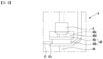
- FIG. 9 is a view showing a charging cable according to the present embodiment when the charging cable is pulled out to the maximum pull-out distance.
- the spring balancer 4 may further comprise a bushing 48; and a stopper 49.
- a through hole through which the wire passes may be formed in the bushing 48.
Landscapes
- Engineering & Computer Science (AREA)
- Power Engineering (AREA)
- Transportation (AREA)
- Mechanical Engineering (AREA)
- Charge And Discharge Circuits For Batteries Or The Like (AREA)
Abstract
Description
- The present disclosure relates to a charger having a charging cable.
- A charger is a device used to charge a battery.
- An example of a charger may be an electric vehicle charger that charges a vehicle such as an electric vehicle, and electric energy is supplied to the battery of the electric vehicle by connecting the charging connector provided at the end of the charging cable to the connection inlet installed in the electric vehicle.
- In order to use the charging cable, the coiled charging cable is unwound and pulled out and then used. Due to its length, the pulled charging cable may touch the floor in the middle, and the part that touches the floor may be damaged, such as worn out by repeated use, and may be contaminated by contaminants on the floor.
- An example of a charging device that can charge a battery is an electric vehicle charging device disclosed in
Korean Patent Publication No. 10-2423210 B (announced on July 21, 2022 - The present embodiment provides a charger capable of improving the durability of a spring balance.
- The present embodiment provides a charger that minimizes the separation of a charging cable from a charger body.
- A charger according to the present embodiment may comprise; a charging cable provided with a coupler connected to a vehicle and connected to a charger body; a spring balancer installed on the charger body and mounting one side of the charging cable; and an output interface disposed on the charger body.
- The spring balancer may comprise: a housing; a rotor rotatably disposed inside the housing; a spring connected to the rotor; and a wire wound around or unwound from the rotor,
- The charger may comprise a sensor detecting a rotation of the rotor.
- The output interface may output information visually or audibly according to a sensing result of the sensor.
- A magnet is disposed on the rotor, and the sensor may comprise a magnetic sensor sensing the magnet.
- The housing may be provided with an opening and the opening is formed in an area facing the sensor.
- The sensor may be mounted on one of the housing and the charger body.
- The output interface may display at least two colors according to a rotational speed of the rotor.
- The output interface may comprise a speaker outputting voice information according to a rotational speed of the rotor.
- The spring balancer may further comprise a bushing fixed to the housing and through which the wire passes; and a stopper fixed to the wire and contacts the bushing when the wire is released by a set length.
- The spring balancer may further comprise a clip on which the charging cable is mounted; and a clip fastening member to which an end of the wire is connected and to which the clip is fastened.
- A through hole through which the wire passes is formed in the bushing, a reduced portion is formed on the stopper, and a cross- sectional are of the reduced portion is gradually reduced, and a gradient portion into which the reduced portion is inserted may formed in the bushing.
- The bushing may comprise a fixed bushing in which a coupling portion is formed to be coupled to the housing; and a buffer bushing in which the gradient portion is formed.
- According to the present embodiment, since the output interface can guide the wire so that it is not excessively pulled, it is possible to minimize breakage or damage to a spring, etc. that may occur when the wire is excessively pulled, and the durability of the spring balancer can be improved.
- In addition, if the stopper is caught in the bushing, the wire can no longer be pulled out, so the charging cable cannot be additionally pulled out, and excessive pulling out or damage to the wire or charging cable can be minimized.
-
-
FIG. 1 is a perspective view of a charger according to the present embodiment, -
FIG. 2 is a view illustrating the inside of a charger according to the present embodiment, -
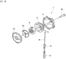
FIG. 3 is an exploded perspective view of a spring balancer according to the present embodiment. -
FIG. 4 is a partially cut-away perspective view of a spring balancer according to the present embodiment, -
FIG. 5 is a side view showing a portion of a spring balancer according to the present embodiment, -
FIG. 6 is a control block diagram of a charger according to the present embodiment, -
FIG. 7 is a view showing the inside of a housing of a spring balancer according to the present embodiment, -
FIG. 8 is a view showing a charging cable according to the present embodiment before the charging cable is pulled out to the maximum pull-out distance, -
FIG. 9 is a view showing a charging cable according to the present embodiment when the charging cable is pulled out to the maximum pull-out distance. - Hereinafter, specific embodiments of the present invention will be described in detail with reference to the drawings.
-
FIG. 1 is a perspective view of a charger according to the present embodiment, andFIG. 2 is a view illustrating the inside of a charger according to the present embodiment. - The charger may comprise a
charger body 1 and acharging cable 2 connected to thecharger body 1. - The
charger body 1 may comprise aframe 11 and anouter case 12 disposed on theframe 11. - The
charger body 1 may comprise a power supply unit (not shown) that supplies power to thecharging cable 2. - The power supply unit may be supported by the
frame 11. The power supply unit may be disposed on the inside of theouter case 12 and may be protected by theouter case 12. - The
outer case 12 may be formed by a combination of a plurality of cover members. - A
cable outlet 13 through which thecharging cable 2 passes may be formed on theouter case 12. - The
charging cable 2 may be drawn out to the outside of thecharger body 2 through thecable outlet 13. - The
charger body 2 may be provided with acoupler holder 14 on which acoupler 3 provided in thecharging cable 2 is placed. Thecoupler holder 14 may be provided on the front or side plate of theouter case 12. - A
display 15 capable of displaying various information such as charging information may be placed on theouter case 12. - The
display 15 may be disposed on the front plate of theouter case 12. - A
coupler 3 connected to a vehicle may be provided on thecharging cable 2. - A connection port that can be connected to a power supply unit (not shown) built into the
charger body 1 may be placed at one end of thecharging cable 2. - A
coupler 3 may be disposed at the other end of thecharging cable 2. - The connection port may be connected to the
charger body 1 and fixed, and thecoupler 3 may be movable outside thecharger body 1. - The length of the portion (hereinafter, referred to as the pull-out cable) of the
charging cable 2 that is pulled out of thecharger body 1 may be changed depending on the position of thecoupler 3. - The length of the pull-out cable of the
charging cable 2 may be changed when thecoupler 3 is pulled. - The
coupler 3 may be a charging gun, and the user may hold thecoupler 3 and use thecharging cable 2. - The
coupler 3 may have a vibration generating portion that generates haptic vibration formed. - The charger may comprise a
spring balancer 4. - The
spring balancer 4 may be installed in thecharger body 1. Thespring balancer 4 may be disposed on the upper portion of thecharger body 1. - One side of the
charging cable 2 may be mounted on thespring balancer 4. One side of the chargingcable 2 may be a portion between the connection port and theconnector 3 of the chargingcable 2. - The
spring balancer 4 may prevent the chargingcable 2 from sagging and may limit the rapid insertion or withdrawal of the chargingcable 2. - The
spring balancer 4 may be a device whose tensile force is adjustable, and if there is no pulling force (external force), it is restored to its original state by the restoring force of the spring, but if there is a pulling force (external force), it may withstand the pulling force and ensure the stability of the position. -
FIG. 3 is an exploded perspective view of a spring balancer according to the present embodiment.FIG. 4 is a partially cut-away perspective view of a spring balancer according to the present embodiment, andFIG. 5 is a side view showing a portion of a spring balancer according to the present embodiment, - The
spring balancer 4 may comprise ahousing 41; arotor 42 rotatably disposed inside thehousing 41; aspring 43 connected to therotor 42; and awire 44 wound around or unwound from therotor 42. - The
spring balancer 4 may be a device that, when thewire 44 is pulled, prevents thewire 44 from returning to its original position and maintains its position, and the tension of thespring 43 may need to be adjusted in advance. - An opening 45 may be formed in the
housing 41. The opening 45 may be formed in an area facing described below asensor 6, and thesensor 6 may sense a rotation angle, etc., of therotor 42, through the opening 65. - A space may be formed inside the
housing 41 to accommodate arotor 42 and aspring 43. - A
cover 41a covering thehousing 41 may be coupled to thehousing 41. - A mounting
hole 41b for mounting aspring balancer 4 may be provided on thehousing 41. The mountinghole 41b may be mounted on theouter case 12 shown inFIG. 1 or theframe 12 shown inFIG. 2 . - The
housing 41 may be mounted to be hung on theouter case 12 or theframe 11. - The
rotor 42 may be rotatably supported on asupport shaft 42a disposed in thehousing 41. An example of therotor 42 may be a disk or drum rotatably disposed in thehousing 41. - An example of the
spring 43 may be a plate spring, and may be accommodated inside thehousing 41 in a rolled form in a scroll shape. - A
spring supporter 43a supporting thespring 43 may be disposed between thehousing 41 and thespring 43. - One end of the
spring 43 may be fixed to thespring supporter 43a or acover 41a, and the other end of thespring 43 may be connected to therotor 42. - One end of the
wire 44 may be connected to therotor 42 and may be wound around the outer surface of therotor 42. - A
clip fastening portion 47 may be connected to the other end of thewire 44. - The
spring balancer 4 may further comprise aclip 46 on which the chargingcable 2 is mounted; and aclip fastening member 47 to which the end of thewire 44 is connected and to which theclip 46 is fastened. - An
outer stopper 50 that comes into contact with thehousing 41 and is restrained by thehousing 41 may be fixed to a portion close to theclip fastening hole 47 of thewire 44. - The
spring balancer 4 may have a drum-shaped structure by therotor 42, and there may be a limit to the stroke length of thewire 44. If the stroke length of thewire 44 is long, the size of thespring balancer 4 may be large. - The
spring balancer 4 may be maintained at a constant force by adjusting the rotation speed according to the stroke of thewire 44 wound around therotor 42 and by the shape of thespring 43. When a force equivalent to the tensile force is applied to thewire 44, almost no additional external force is required while thewire 44 is released to the maximum stroke of thewire 44. -
FIG. 6 is a control block diagram of a charger according to the present embodiment. - The charger may comprise an
output interface 5 disposed in thecharger body 1, asensor 6 sensing the rotation of therotor 42, and acontrol unit 7 configured to control theoutput interface 5 according to the sensing result of thesensor 6. - The
output interface 5 may output information visually, audibly, or tactilely according to the sensing result of thesensor 6. - An example of the
output interface 5 may be a visual interface that visually displays information. An example of theoutput interface 5 may display at least two colors according to the rotational speed of therotor 42. - An example of the visual interface may be at least one indicator light that displays various information of the charger.
- The indicator light may express a plurality of colors as one indicator light, or may express different colors as the plurality of indicator
- Another example of the visual interface may comprise a
display 15 that displays various information of the charger. - The indicator light or display may display blue, yellow, red, etc. depending on the degree (i.e., the number of rotations of the
rotor 42.) to which therotor 42 is rotated - The visual interface may express different colors depending on the length of the withdrawal wire among the
wires 44. - The visual interface may display blue when the length of the withdrawal wire is 0 to 1 m, yellow when the length of the withdrawal wire exceeds 1 and is less than 1.3 m, and red when the length of the withdrawal wire exceeds 1.3 m.
- Another example of the
output interface 5 may comprise a speaker that outputs voice information depending on the number of rotations of therotor 42. - The speaker may be an auditory interface and may output voice information depending on the degree (i.e., the number of rotations of the
rotor 42.) to which therotor 42 is rotated - The auditory interface may output different voice information depending on the length of the lead cable among the charging
cables 2. - The auditory interface may output first voice information such as "safe" when the length of the withdrawal wire is 0 to 1 m, output second voice information such as "a little safe" when the length of the withdrawal wire is more than 1 and less than 1.3 m, and output third voice information such as "danger" when the length of the withdrawal wire is more than 1.3 m.
- The auditory interface may also output a buzzer, output a buzzer with a first time difference when the length of the withdrawal wire is 0 to 1 m, output a buzzer with a second time difference that is shorter than the first time difference when the length of the withdrawal wire is more than 1 and less than 1.3 m, and output a buzzer with a third time difference that is shorter than the second time difference when the length of the withdrawal wire is more than 1.3 m.
- The auditory interface may also output voice information by controlling the intensity, and when the length of the withdrawal wire is 0 to 1 m, it may output low-pitched voice information, and when the length of the withdrawal wire is more than 1 and less than 1.3 m, it may output mid-pitched voice information shorter than the first time difference, and when the length of the withdrawal wire is 1.3 m or more, it may output high-pitched voice information.
- The other example of the
output interface 5 may be a tactile interface that generates haptic vibration, etc. - The tactile interface may comprise a vibration generating unit disposed in the
coupler 3. - The tactile interface may also output tactile information by controlling the time or intensity, and, like the visual interface, may generate different haptic vibrations depending on the length of the withdrawal wire.
- It goes without saying that the
output interface 5 may comprise a visual interface, an auditory interface, and a tactile interface. - If the
output interface 5 outputs visual information, voice information, or tactile information, excessive pulling of the chargingcable 2 may be primarily limited, and damage to thespring 44 or the like due to external force may be minimized. - The
sensor 6 may detect the rotation of therotor 42 and sense the length of the portion (withdrawal wire) of thewire 44 that is exposed to the outside of thehousing 41. - The
sensor 6 may detect therotor 42 of thespring balancer 4. Thesensor 6 may be a sensor that may detect the degree to which therotor 41 has rotated, and by sensing the rotation angle of therotor 41, the length of thewire 44 released from therotor 41 may be confirmed. - The
sensor 6 may be an optical sensor that optically senses the rotation angle of therotor 42, an ultrasonic sensor that senses the rotation angle of therotor 42 using ultrasonic waves, or a magnetic sensor that senses the rotation angle of therotor 42 using a magnetic field. - Hereinafter, the
sensor 6 is described as including a magnetic sensor, but it is of course applicable without limitation to the type as long as it may sense the rotation angle of therotor 42. - A magnet may be disposed on the
rotor 42, and thesensor 6 may comprise a magnetic sensor that senses the magnet. - The
sensor 6 may be mounted on one of thehousing 41 and thecharger body 1. - The
sensor 6 may transmit a signal according to the sensing value to thecontrol unit 7. - The
control unit 7 may calculate the length of the withdrawal wire according to the signal value transmitted from thesensor 6 and output a control signal to theoutput interface 5 according to the length of the withdrawal wire. -
FIG. 7 is a view showing the inside of a housing of a spring balancer according to the present embodiment,FIG. 8 is a view showing a charging cable according to the present embodiment before the charging cable is pulled out to the maximum pull-out distance, andFIG. 9 is a view showing a charging cable according to the present embodiment when the charging cable is pulled out to the maximum pull-out distance. - The
spring balancer 4 may further comprise abushing 48; and astopper 49. - The
bushing 48 may be fixed to thehousing 41, and thewire 44 may pass through thebushing 48. A mountinghole 41c in which thebushing 48 is mounted may be formed in thehousing 41. - A through hole through which the wire passes may be formed in the
bushing 48. - A
gradient portion 48a may be formed in thebushing 48. - The
gradient portion 48a may be formed in a recessed shape in thebushing 48. - The
bushing 48 may comprise a fixedbushing 48c having acoupling portion 48b formed on the fixedbushing 48c, which is coupled to thehousing 41. - The
coupling portion 48b may comprise a recessed recess in the outer surface of the fixedbushing 48c. - The
bushing 48 may further comprise abuffer bushing 48d having agradient portion 48a formed therein. - An example of the
bushing 48 may be a fixedbushing 48c and abuffer bushing 48d formed integrally. - The other example of the
bushing 48 may comprise a fixedbushing 48c formed of metal or plastic, and abuffer bushing 48d formed of a buffering material such as rubber. - The
stopper 49 may be fixed to thewire 44. Thestopper 49 may be caught by contacting thebushing 48 when thewire 44 is released by a set length. - Here, the set length may be the maximum draw length of the draw wire, and may be, for example, 1.3 m.
- The set length may be the length from the mounting
hole 41c of the chargingcable 2 to thestopper 49. - The
stopper 49 may be formed with a reducedportion 49a whose cross-sectional area is gradually reduced, and the reducedportion 49a may be inserted into thegradient portion 48a of thebushing 48. - The reduced
portion 49a may be formed at one end of thestopper 49 for example, the lower end of thestopper 49. - A person with impaired mobility, such as an infant or toddler, may continue to pull the charging
cable 2, but if thestopper 49 comes into contact with thebushing 48 and gets caught in thebushing 48, thewire 44 may no longer be pulled out, the chargingcable 2 may no longer be pulled out, excessive pulling out of the chargingcable 2 may be secondarily limited, and damage to thespring 44 or the like due to external force may be minimized. - The
bushing 48 andstopper 49 may forcibly brake thewire 44, thereby preventing excessive load from being applied to thewire 44, and minimizing breakage of thewire 44 or damage to thespring 43. - The above description is merely an illustrative explanation of the technical idea of the present disclosure, and various modifications and variations will be possible to those skilled in the art without departing from the essential characteristics of the present disclosure.
- Accordingly, the embodiments disclosed in the present disclosure are not intended to limit the technical idea of the present disclosure, but rather to explain it, and the scope of the technical idea of the present disclosure is not limited by these embodiments.
- The scope of protection of the present disclosure should be interpreted in accordance with the claims below, and all technical ideas within the equivalent scope should be construed as being comprised in the scope of rights of the present disclosure.
Claims (10)
- A charger comprising;a charging cable provided with a coupler connected to a vehicle and connected to a charger body;a spring balancer installed on the charger body and mounting one side of the charging cable; andan output interface disposed on the charger body,wherein the spring balancer comprises:a housing;a rotor rotatably disposed inside the housing;a spring connected to the rotor; anda wire wound around or unwound from the rotor,wherein the charger further comprises a sensor detecting a rotation of the rotor,wherein the output interface outputs information visually or audibly according to a sensing result of the sensor.
- The charger of claim 1,wherein a magnet is disposed on the rotor;wherein the sensor comprises a magnetic sensor sensing the magnet.
- The charger of claim 1,
wherein the housing is provided with an opening and the opening is formed in an area facing the sensor. - The charger of claim 1,
wherein the sensor is mounted on one of the housing and the charger body. - The charger of claim 1,
Wherein the output interface displays at least two colors according to a rotational speed of the rotor. - The charger of claim 1,
wherein the output interface comprises a speaker outputting voice information according to a rotational speed of the rotor. - The charger of claim 1,wherein the spring balancer further comprisesa bushing fixed to the housing and through which the wire passes; anda stopper fixed to the wire and contacts the bushing when the wire is released by a set length.
- The charger of claim 7,wherein the spring balancer further comprisesa clip on which the charging cable is mounted; anda clip fastening member to which an end of the wire is connected and to which the clip is fastened.
- The charger of claim 7,wherein a through hole through which the wire passes is formed in the bushing,wherein a reduced portion is formed on the stopper, and a cross- sectional are of the reduced portion is gradually reduced,wherein a gradient portion into which the reduced portion is inserted is formed in the bushing.
- 11. The charger of claim 9,wherein the bushing comprisesa fixed bushing in which a coupling portion is formed to be coupled to the housing; anda buffer bushing in which the gradient portion is formed.
Applications Claiming Priority (1)
| Application Number | Priority Date | Filing Date | Title |
|---|---|---|---|
| PCT/KR2023/017007 WO2025095153A1 (en) | 2023-10-30 | 2023-10-30 | Charger |
Publications (1)
| Publication Number | Publication Date |
|---|---|
| EP4582298A1 true EP4582298A1 (en) | 2025-07-09 |
Family
ID=95582459
Family Applications (1)
| Application Number | Title | Priority Date | Filing Date |
|---|---|---|---|
| EP23951048.0A Withdrawn EP4582298A1 (en) | 2023-10-30 | 2023-10-30 | Charger |
Country Status (3)
| Country | Link |
|---|---|
| EP (1) | EP4582298A1 (en) |
| KR (1) | KR20250065326A (en) |
| WO (1) | WO2025095153A1 (en) |
Family Cites Families (6)
| Publication number | Priority date | Publication date | Assignee | Title |
|---|---|---|---|---|
| JP3491088B2 (en) * | 2002-01-16 | 2004-01-26 | 株式会社ニチフ端子工業 | Stirring fan capable of self-diagnosis and its operation confirmation device |
| KR101188913B1 (en) * | 2009-11-13 | 2012-10-08 | (주)포스프로 | Position measuring apparatus for charging materials of blast furnace |
| KR20180128557A (en) * | 2017-05-24 | 2018-12-04 | 김태붕 | Charging cable winding apparatus for the electric vehicle charger |
| KR102423210B1 (en) | 2021-11-05 | 2022-07-21 | 보타리에너지 주식회사 | Electric vehicle charging station for people with disablities |
| KR20230103849A (en) * | 2021-12-30 | 2023-07-07 | 세메스 주식회사 | Satefy apparatus for blocking from load port of semiconductor manufacturing equipment |
| EP4242752B1 (en) * | 2022-03-11 | 2026-01-21 | ETA SA Manufacture Horlogère Suisse | Device for guiding a shaft of a balance wheel with hairspring |
-
2023
- 2023-10-30 EP EP23951048.0A patent/EP4582298A1/en not_active Withdrawn
- 2023-10-30 KR KR1020257005308A patent/KR20250065326A/en not_active Withdrawn
- 2023-10-30 WO PCT/KR2023/017007 patent/WO2025095153A1/en active Pending
Also Published As
| Publication number | Publication date |
|---|---|
| WO2025095153A1 (en) | 2025-05-08 |
| KR20250065326A (en) | 2025-05-12 |
Similar Documents
| Publication | Publication Date | Title |
|---|---|---|
| KR102331365B1 (en) | Charger for electic vehicle charger | |
| CN103183259B (en) | Take-up device | |
| EP4299967A1 (en) | Display device | |
| US9984802B2 (en) | Electronic device having a magnetic on-off switch | |
| US20100274932A1 (en) | Control system, operation device and control method | |
| WO2020000257A1 (en) | Electric vehicle-mounted support | |
| EP4582298A1 (en) | Charger | |
| EP2829432A2 (en) | Portable charger | |
| KR20210004480A (en) | Rapidly charging cable arrangement apparatus for electric vehicle | |
| EP3552297B1 (en) | Display apparatus, display system, and driving method of the same | |
| WO2018052194A1 (en) | Length measurement device and control method therefor | |
| JP3143572U (en) | Rope damage detection device | |
| CN108683036A (en) | Charging gun with automatic wire-rewinding function and control method of charging gun | |
| EP3093732A1 (en) | Electronic apparatus and method for controlling thereof | |
| KR20240038056A (en) | electronic glasses | |
| JP2012200054A (en) | Charging system | |
| KR102342238B1 (en) | Apparatus for wireless charging based on state of terminal | |
| CN213912131U (en) | Strength type fitness equipment | |
| CN111478381B (en) | Charger, charging system and charging terminal detachment method | |
| JP3277224B2 (en) | Drive sensor type tank liquid level gauge | |
| CN210133766U (en) | Optical cable paying-off tension control device | |
| CN209745397U (en) | Sound level meter | |
| JP2003224909A (en) | Winding/traction apparatus | |
| EP4592132A1 (en) | Charger | |
| CN216449067U (en) | Magnetic induction pressure measuring device of electric toothbrush |
Legal Events
| Date | Code | Title | Description |
|---|---|---|---|
| STAA | Information on the status of an ep patent application or granted ep patent |
Free format text: STATUS: UNKNOWN |
|
| STAA | Information on the status of an ep patent application or granted ep patent |
Free format text: STATUS: THE INTERNATIONAL PUBLICATION HAS BEEN MADE |
|
| PUAI | Public reference made under article 153(3) epc to a published international application that has entered the european phase |
Free format text: ORIGINAL CODE: 0009012 |
|
| STAA | Information on the status of an ep patent application or granted ep patent |
Free format text: STATUS: REQUEST FOR EXAMINATION WAS MADE |
|
| 17P | Request for examination filed |
Effective date: 20250317 |
|
| AK | Designated contracting states |
Kind code of ref document: A1 Designated state(s): AL AT BE BG CH CY CZ DE DK EE ES FI FR GB GR HR HU IE IS IT LI LT LU LV MC ME MK MT NL NO PL PT RO RS SE SI SK SM TR |
|
| STAA | Information on the status of an ep patent application or granted ep patent |
Free format text: STATUS: THE APPLICATION HAS BEEN WITHDRAWN |
|
| 18W | Application withdrawn |
Effective date: 20250804 |