EP4582293A1 - Drive apparatus - Google Patents
Drive apparatus Download PDFInfo
- Publication number
- EP4582293A1 EP4582293A1 EP24221679.4A EP24221679A EP4582293A1 EP 4582293 A1 EP4582293 A1 EP 4582293A1 EP 24221679 A EP24221679 A EP 24221679A EP 4582293 A1 EP4582293 A1 EP 4582293A1
- Authority
- EP
- European Patent Office
- Prior art keywords
- rotating electrical
- oil
- electrical machine
- refrigerant
- cool
- Prior art date
- Legal status (The legal status is an assumption and is not a legal conclusion. Google has not performed a legal analysis and makes no representation as to the accuracy of the status listed.)
- Pending
Links
Images


Classifications
-
- B—PERFORMING OPERATIONS; TRANSPORTING
- B60—VEHICLES IN GENERAL
- B60K—ARRANGEMENT OR MOUNTING OF PROPULSION UNITS OR OF TRANSMISSIONS IN VEHICLES; ARRANGEMENT OR MOUNTING OF PLURAL DIVERSE PRIME-MOVERS IN VEHICLES; AUXILIARY DRIVES FOR VEHICLES; INSTRUMENTATION OR DASHBOARDS FOR VEHICLES; ARRANGEMENTS IN CONNECTION WITH COOLING, AIR INTAKE, GAS EXHAUST OR FUEL SUPPLY OF PROPULSION UNITS IN VEHICLES
- B60K11/00—Arrangement in connection with cooling of propulsion units
- B60K11/02—Arrangement in connection with cooling of propulsion units with liquid cooling
-
- B—PERFORMING OPERATIONS; TRANSPORTING
- B60—VEHICLES IN GENERAL
- B60L—PROPULSION OF ELECTRICALLY-PROPELLED VEHICLES; SUPPLYING ELECTRIC POWER FOR AUXILIARY EQUIPMENT OF ELECTRICALLY-PROPELLED VEHICLES; ELECTRODYNAMIC BRAKE SYSTEMS FOR VEHICLES IN GENERAL; MAGNETIC SUSPENSION OR LEVITATION FOR VEHICLES; MONITORING OPERATING VARIABLES OF ELECTRICALLY-PROPELLED VEHICLES; ELECTRIC SAFETY DEVICES FOR ELECTRICALLY-PROPELLED VEHICLES
- B60L50/00—Electric propulsion with power supplied within the vehicle
- B60L50/10—Electric propulsion with power supplied within the vehicle using propulsion power supplied by engine-driven generators, e.g. generators driven by combustion engines
- B60L50/16—Electric propulsion with power supplied within the vehicle using propulsion power supplied by engine-driven generators, e.g. generators driven by combustion engines with provision for separate direct mechanical propulsion
-
- H—ELECTRICITY
- H02—GENERATION; CONVERSION OR DISTRIBUTION OF ELECTRIC POWER
- H02K—DYNAMO-ELECTRIC MACHINES
- H02K9/00—Arrangements for cooling or ventilating
- H02K9/19—Arrangements for cooling or ventilating for machines with closed casing and closed-circuit cooling using a liquid cooling medium, e.g. oil
- H02K9/193—Arrangements for cooling or ventilating for machines with closed casing and closed-circuit cooling using a liquid cooling medium, e.g. oil with provision for replenishing the cooling medium; with means for preventing leakage of the cooling medium
-
- B—PERFORMING OPERATIONS; TRANSPORTING
- B60—VEHICLES IN GENERAL
- B60K—ARRANGEMENT OR MOUNTING OF PROPULSION UNITS OR OF TRANSMISSIONS IN VEHICLES; ARRANGEMENT OR MOUNTING OF PLURAL DIVERSE PRIME-MOVERS IN VEHICLES; AUXILIARY DRIVES FOR VEHICLES; INSTRUMENTATION OR DASHBOARDS FOR VEHICLES; ARRANGEMENTS IN CONNECTION WITH COOLING, AIR INTAKE, GAS EXHAUST OR FUEL SUPPLY OF PROPULSION UNITS IN VEHICLES
- B60K1/00—Arrangement or mounting of electrical propulsion units
- B60K1/02—Arrangement or mounting of electrical propulsion units comprising more than one electric motor
-
- B—PERFORMING OPERATIONS; TRANSPORTING
- B60—VEHICLES IN GENERAL
- B60L—PROPULSION OF ELECTRICALLY-PROPELLED VEHICLES; SUPPLYING ELECTRIC POWER FOR AUXILIARY EQUIPMENT OF ELECTRICALLY-PROPELLED VEHICLES; ELECTRODYNAMIC BRAKE SYSTEMS FOR VEHICLES IN GENERAL; MAGNETIC SUSPENSION OR LEVITATION FOR VEHICLES; MONITORING OPERATING VARIABLES OF ELECTRICALLY-PROPELLED VEHICLES; ELECTRIC SAFETY DEVICES FOR ELECTRICALLY-PROPELLED VEHICLES
- B60L15/00—Methods, circuits, or devices for controlling the traction-motor speed of electrically-propelled vehicles
- B60L15/32—Control or regulation of multiple-unit electrically-propelled vehicles
-
- B—PERFORMING OPERATIONS; TRANSPORTING
- B60—VEHICLES IN GENERAL
- B60L—PROPULSION OF ELECTRICALLY-PROPELLED VEHICLES; SUPPLYING ELECTRIC POWER FOR AUXILIARY EQUIPMENT OF ELECTRICALLY-PROPELLED VEHICLES; ELECTRODYNAMIC BRAKE SYSTEMS FOR VEHICLES IN GENERAL; MAGNETIC SUSPENSION OR LEVITATION FOR VEHICLES; MONITORING OPERATING VARIABLES OF ELECTRICALLY-PROPELLED VEHICLES; ELECTRIC SAFETY DEVICES FOR ELECTRICALLY-PROPELLED VEHICLES
- B60L50/00—Electric propulsion with power supplied within the vehicle
- B60L50/50—Electric propulsion with power supplied within the vehicle using propulsion power supplied by batteries or fuel cells
- B60L50/60—Electric propulsion with power supplied within the vehicle using propulsion power supplied by batteries or fuel cells using power supplied by batteries
- B60L50/61—Electric propulsion with power supplied within the vehicle using propulsion power supplied by batteries or fuel cells using power supplied by batteries by batteries charged by engine-driven generators, e.g. series hybrid electric vehicles
-
- B—PERFORMING OPERATIONS; TRANSPORTING
- B60—VEHICLES IN GENERAL
- B60L—PROPULSION OF ELECTRICALLY-PROPELLED VEHICLES; SUPPLYING ELECTRIC POWER FOR AUXILIARY EQUIPMENT OF ELECTRICALLY-PROPELLED VEHICLES; ELECTRODYNAMIC BRAKE SYSTEMS FOR VEHICLES IN GENERAL; MAGNETIC SUSPENSION OR LEVITATION FOR VEHICLES; MONITORING OPERATING VARIABLES OF ELECTRICALLY-PROPELLED VEHICLES; ELECTRIC SAFETY DEVICES FOR ELECTRICALLY-PROPELLED VEHICLES
- B60L53/00—Methods of charging batteries, specially adapted for electric vehicles; Charging stations or on-board charging equipment therefor; Exchange of energy storage elements in electric vehicles
- B60L53/20—Methods of charging batteries, specially adapted for electric vehicles; Charging stations or on-board charging equipment therefor; Exchange of energy storage elements in electric vehicles characterised by converters located in the vehicle
- B60L53/24—Using the vehicle's propulsion converter for charging
-
- H—ELECTRICITY
- H02—GENERATION; CONVERSION OR DISTRIBUTION OF ELECTRIC POWER
- H02K—DYNAMO-ELECTRIC MACHINES
- H02K16/00—Machines with more than one rotor or stator
-
- H—ELECTRICITY
- H02—GENERATION; CONVERSION OR DISTRIBUTION OF ELECTRIC POWER
- H02K—DYNAMO-ELECTRIC MACHINES
- H02K5/00—Casings; Enclosures; Supports
- H02K5/04—Casings or enclosures characterised by the shape, form or construction thereof
- H02K5/20—Casings or enclosures characterised by the shape, form or construction thereof with channels or ducts for flow of cooling medium
- H02K5/203—Casings or enclosures characterised by the shape, form or construction thereof with channels or ducts for flow of cooling medium specially adapted for liquids, e.g. cooling jackets
-
- H—ELECTRICITY
- H02—GENERATION; CONVERSION OR DISTRIBUTION OF ELECTRIC POWER
- H02K—DYNAMO-ELECTRIC MACHINES
- H02K9/00—Arrangements for cooling or ventilating
- H02K9/19—Arrangements for cooling or ventilating for machines with closed casing and closed-circuit cooling using a liquid cooling medium, e.g. oil
-
- B—PERFORMING OPERATIONS; TRANSPORTING
- B60—VEHICLES IN GENERAL
- B60K—ARRANGEMENT OR MOUNTING OF PROPULSION UNITS OR OF TRANSMISSIONS IN VEHICLES; ARRANGEMENT OR MOUNTING OF PLURAL DIVERSE PRIME-MOVERS IN VEHICLES; AUXILIARY DRIVES FOR VEHICLES; INSTRUMENTATION OR DASHBOARDS FOR VEHICLES; ARRANGEMENTS IN CONNECTION WITH COOLING, AIR INTAKE, GAS EXHAUST OR FUEL SUPPLY OF PROPULSION UNITS IN VEHICLES
- B60K1/00—Arrangement or mounting of electrical propulsion units
- B60K2001/003—Arrangement or mounting of electrical propulsion units with means for cooling the electrical propulsion units
-
- B—PERFORMING OPERATIONS; TRANSPORTING
- B60—VEHICLES IN GENERAL
- B60K—ARRANGEMENT OR MOUNTING OF PROPULSION UNITS OR OF TRANSMISSIONS IN VEHICLES; ARRANGEMENT OR MOUNTING OF PLURAL DIVERSE PRIME-MOVERS IN VEHICLES; AUXILIARY DRIVES FOR VEHICLES; INSTRUMENTATION OR DASHBOARDS FOR VEHICLES; ARRANGEMENTS IN CONNECTION WITH COOLING, AIR INTAKE, GAS EXHAUST OR FUEL SUPPLY OF PROPULSION UNITS IN VEHICLES
- B60K1/00—Arrangement or mounting of electrical propulsion units
- B60K2001/003—Arrangement or mounting of electrical propulsion units with means for cooling the electrical propulsion units
- B60K2001/006—Arrangement or mounting of electrical propulsion units with means for cooling the electrical propulsion units the electric motors
-
- B—PERFORMING OPERATIONS; TRANSPORTING
- B60—VEHICLES IN GENERAL
- B60L—PROPULSION OF ELECTRICALLY-PROPELLED VEHICLES; SUPPLYING ELECTRIC POWER FOR AUXILIARY EQUIPMENT OF ELECTRICALLY-PROPELLED VEHICLES; ELECTRODYNAMIC BRAKE SYSTEMS FOR VEHICLES IN GENERAL; MAGNETIC SUSPENSION OR LEVITATION FOR VEHICLES; MONITORING OPERATING VARIABLES OF ELECTRICALLY-PROPELLED VEHICLES; ELECTRIC SAFETY DEVICES FOR ELECTRICALLY-PROPELLED VEHICLES
- B60L2210/00—Converter types
- B60L2210/10—DC to DC converters
- B60L2210/14—Boost converters
-
- B—PERFORMING OPERATIONS; TRANSPORTING
- B60—VEHICLES IN GENERAL
- B60L—PROPULSION OF ELECTRICALLY-PROPELLED VEHICLES; SUPPLYING ELECTRIC POWER FOR AUXILIARY EQUIPMENT OF ELECTRICALLY-PROPELLED VEHICLES; ELECTRODYNAMIC BRAKE SYSTEMS FOR VEHICLES IN GENERAL; MAGNETIC SUSPENSION OR LEVITATION FOR VEHICLES; MONITORING OPERATING VARIABLES OF ELECTRICALLY-PROPELLED VEHICLES; ELECTRIC SAFETY DEVICES FOR ELECTRICALLY-PROPELLED VEHICLES
- B60L2210/00—Converter types
- B60L2210/40—DC to AC converters
-
- B—PERFORMING OPERATIONS; TRANSPORTING
- B60—VEHICLES IN GENERAL
- B60L—PROPULSION OF ELECTRICALLY-PROPELLED VEHICLES; SUPPLYING ELECTRIC POWER FOR AUXILIARY EQUIPMENT OF ELECTRICALLY-PROPELLED VEHICLES; ELECTRODYNAMIC BRAKE SYSTEMS FOR VEHICLES IN GENERAL; MAGNETIC SUSPENSION OR LEVITATION FOR VEHICLES; MONITORING OPERATING VARIABLES OF ELECTRICALLY-PROPELLED VEHICLES; ELECTRIC SAFETY DEVICES FOR ELECTRICALLY-PROPELLED VEHICLES
- B60L2240/00—Control parameters of input or output; Target parameters
- B60L2240/10—Vehicle control parameters
- B60L2240/36—Temperature of vehicle components or parts
-
- B—PERFORMING OPERATIONS; TRANSPORTING
- B60—VEHICLES IN GENERAL
- B60L—PROPULSION OF ELECTRICALLY-PROPELLED VEHICLES; SUPPLYING ELECTRIC POWER FOR AUXILIARY EQUIPMENT OF ELECTRICALLY-PROPELLED VEHICLES; ELECTRODYNAMIC BRAKE SYSTEMS FOR VEHICLES IN GENERAL; MAGNETIC SUSPENSION OR LEVITATION FOR VEHICLES; MONITORING OPERATING VARIABLES OF ELECTRICALLY-PROPELLED VEHICLES; ELECTRIC SAFETY DEVICES FOR ELECTRICALLY-PROPELLED VEHICLES
- B60L2240/00—Control parameters of input or output; Target parameters
- B60L2240/40—Drive Train control parameters
- B60L2240/42—Drive Train control parameters related to electric machines
- B60L2240/425—Temperature
-
- B—PERFORMING OPERATIONS; TRANSPORTING
- B60—VEHICLES IN GENERAL
- B60L—PROPULSION OF ELECTRICALLY-PROPELLED VEHICLES; SUPPLYING ELECTRIC POWER FOR AUXILIARY EQUIPMENT OF ELECTRICALLY-PROPELLED VEHICLES; ELECTRODYNAMIC BRAKE SYSTEMS FOR VEHICLES IN GENERAL; MAGNETIC SUSPENSION OR LEVITATION FOR VEHICLES; MONITORING OPERATING VARIABLES OF ELECTRICALLY-PROPELLED VEHICLES; ELECTRIC SAFETY DEVICES FOR ELECTRICALLY-PROPELLED VEHICLES
- B60L2240/00—Control parameters of input or output; Target parameters
- B60L2240/40—Drive Train control parameters
- B60L2240/52—Drive Train control parameters related to converters
- B60L2240/525—Temperature of converter or components thereof
-
- Y—GENERAL TAGGING OF NEW TECHNOLOGICAL DEVELOPMENTS; GENERAL TAGGING OF CROSS-SECTIONAL TECHNOLOGIES SPANNING OVER SEVERAL SECTIONS OF THE IPC; TECHNICAL SUBJECTS COVERED BY FORMER USPC CROSS-REFERENCE ART COLLECTIONS [XRACs] AND DIGESTS
- Y02—TECHNOLOGIES OR APPLICATIONS FOR MITIGATION OR ADAPTATION AGAINST CLIMATE CHANGE
- Y02T—CLIMATE CHANGE MITIGATION TECHNOLOGIES RELATED TO TRANSPORTATION
- Y02T10/00—Road transport of goods or passengers
- Y02T10/60—Other road transportation technologies with climate change mitigation effect
- Y02T10/64—Electric machine technologies in electromobility
Definitions
- the refrigerant that is pressure-fed to the second upstream route 66L by the second radiator pump 64L flows to the second inverter 40L, the second midstream route 67L, the first oil cooler 22R, the second downstream route 68R, the merging route 69, and the radiator 60 in the stated order.
- the drive apparatus 20 includes an electricity supply circuit 11 in addition to the pair of electric motors 30R, 30L and the pair of inverters 40R, 40L.
- the electricity supply circuit 11 is a circuit for supplying DC charging electricity supplied from the external power source 7 to the battery pack 3.
- the first electric motor 30R is a three-phase motor including a U-phase coil 35U, a V-phase coil 35V, and a W-phase coil 35W.
- the first inverter 40R includes a U-phase arm 42U, a V-phase arm 42V, and a W-phase arm 42W. Each of the phase arms 42U, 42V, 42W has two switching elements in series.
- the first inverter 40R is an electricity conversion apparatus that converts the DC electricity supplied from the battery pack 3 to three-phase AC electricity suitable for the driving of the first electric motor 30R by turning the switching elements of each of the phase arms 42U, 42V, 42W ON and OFF.
- One end of each of the U-phase coil 35U, the V-phase coil 35V, and the W-phase coil 35W of the first electric motor 30R is connected to each other at a neutral point NP.
- the second electric motor 30L includes the U-phase coil 35U, the V-phase coil 35V, and the W-phase coil 35W
- the second inverter 40L includes the U-phase arm 42U, the V-phase arm 42V, and the W-phase arm 42W.
- Each of the phase arms 42U, 42V, 42W has two switching elements in series.
- the second inverter 40L is an electricity conversion apparatus that converts the DC electricity supplied from the battery pack 3 to three-phase AC electricity suitable for the driving of the second electric motor 30L by turning the switching elements of each of the phase arms 42U, 42V, 42W ON and OFF.
- each of the U-phase coil 35U, the V-phase coil 35V, and the W-phase coil 35W is connected to each other at the neutral point NP, the other end of the U-phase coil 35U is connected to a midpoint of the two switching elements of the U-phase arm 42U, the other end of the V-phase coil 35V is connected to a midpoint of the two switching elements of the V-phase arm 42V, and the W-phase coil 35W is connected to a midpoint of the two switching elements of the W-phase arm 42W.
- the second inverter 40L is electrically connected to the second electric motor 30L.
- one terminal of the charging inlet 6 is connected to a positive electrode of the battery pack 3 via the neutral point NP of the first electric motor 30R and the first inverter 40R.
- the electricity supply circuit 11 supplies the charging electricity supplied from the external power source 7 to the neutral point NP of the first electric motor 30R.
- the other terminal of the charging inlet 6 is connected to a negative electrode of the battery pack 3 via the first inverter 40R.
- the electricity supply circuit 11 supplies the charging electricity to the battery pack 3 via the neutral point NP of the first electric motor 30R.
- the first electric motor 30R and the first inverter 40R can function as three voltage boosting circuits parallelly connected to each other between the charging inlet 6 and the battery pack 3.
- the drive apparatus 20 can boost the output voltage of the external power source 7 with use of the first electric motor 30R and the first inverter 40R.
- quick charging can be executed even when the output voltage of the external power source 7 is lower than the voltage across the battery pack 3.
- One terminal of the charging inlet 6 is directly connected to the positive electrode of the battery pack 3 via a switch 13.
- the electricity supply circuit 11 can cause the output voltage of the external power source 7 to bypass the neutral point NP of the first electric motor 30R by turning ON the switch 13 when the output voltage of the external power source 7 is equivalent to the voltage across the battery pack 3.
- the electricity supply circuit 11 further includes a charging unit including a relay, a capacitor, and the like. The charging unit is connected to the neutral point NP and the first inverter 40R.
- the charging electricity of the external power source 7 is supplied to the neutral point NP of the first electric motor 30R.
- a period of time in which the charging electricity is supplied to the battery pack 3 via the supply to the neutral point NP of the first electric motor 30R may be hereinafter referred to as "a period of charging time".
- the current flows to the coils 35U, 35V, 35W of each phase of the first electric motor 30R over the period of charging time. As a result, the coils 35U, 35V, 35W of each phase generate heat, and the temperature of the first electric motor 30R rises.
- the switching elements of each of the phase arms 42U, 42V, 42W of the first inverter 40R electrically connected to the first electric motor 30R are turned ON and OFF.
- the temperature of the first inverter 40R rises.
- the current does not flow to the coils 35U, 35V, 35W of each phase of the second electric motor 30L, and hence the temperature of the second electric motor 30L does not rise. Therefore, the temperature of the second inverter 40L electrically connected to the second electric motor 30L does not rise either.
- FIG. 3 is a sectional view of the drive apparatus taken along line III-III in FIG. 1 .
- the drive apparatus 20 further includes a pair of oil pumps 70R, 70L, a pair of suction pipes 72R, 72L, and a pair of discharge pipes 74R, 74L accommodated in the casing 21 in addition to the pair of electric motors 30R, 30L and the like described above.
- the casing 21 includes a dividing wall 26 extending to the lower side at the center in the left-right direction.
- the dividing wall 26 is a wall that separates a right space and a left space of the casing 21 from each other. However, the dividing wall 26 does not reach to a bottom surface of the casing 21.
- the right space and the left space of the casing 21 communicate with each other in a lower portion of the casing 21.
- the first electric motor 30R and the first motive power transmission mechanism 50R are disposed on the right side of the dividing wall 26.
- the second electric motor 30L and the second motive power transmission mechanism 50L are disposed on the left side of the dividing wall 26.
- the drive apparatus 20 is configured to be left-right symmetrical about the center of the dividing wall 26, in other words, a center line CL1. Therefore, a configuration positioned on the right side of the center line CL1 of the drive apparatus 20 is mainly described below.
- the first electric motor 30R includes a motor shaft 33R, a rotor 34R, and a stator 35R.
- the motor shaft 33R passes through the rotor 34R and extends in the left-right direction, and is rotatably maintained in the casing 21 by a pair of bearings 39R.
- the motor shaft 33R extends to the left side so as to exceed a left end of the rotor 34R and is connected to the gears of the first motive power transmission mechanism 50R.
- the gears of the first motive power transmission mechanism 50R rotate.
- the first motive power transmission mechanism 50R rotates the right drive shaft 14R (see FIG. 1 ) via the gears.
- the first motive power transmission mechanism 50R transmits the motive power of the first electric motor 30R to the right drive shaft 14R.
- the motor shaft 33R has a hollow structure.
- a plurality of through-holes 38R is formed in a side surface of the motor shaft 33R.
- the through-holes 38R communicate with the inner space of the motor shaft 33R and the inner space of the casing 21.
- FIG. 1 only the two through-holes 38R positioned in a right end out of the through-holes 38R are denoted by reference characters, and reference characters of the other through-holes 38R are omitted.
- the second electric motor 30L includes a motor shaft 33L, a rotor 34L, and a stator 35L.
- the motor shaft 33L passes through the rotor 34L and extends in the left-right direction, and is rotatably maintained in the casing 21 by a pair of bearings 39L.
- the second motive power transmission mechanism 50L also transmits the motive power of the second electric motor 30L to the left drive shaft 14L via a gear and the like connected to the motor shaft 33L of the second electric motor 30L.
- the pair of oil pumps 70R, 70L includes the first oil pump 70R positioned on the right side and the second oil pump 70L positioned on the left side.
- the first oil pump 70R is fixed to the dividing wall 26 from the right side.
- the first oil pump 70R is a pump that supplies the oil 76 to the first electric motor 30R.
- the pair of suction pipes 72R, 72L includes the first suction pipe 72R positioned on the right side and the second suction pipe 72L positioned on the left side.
- the first suction pipe 72R extends to the upper side from the oil sump, bends to the left side, and is connected to a suction port of the first oil pump 70R.
- the pair of discharge pipes 74R, 74L includes the first discharge pipe 74R positioned on the right side and the second discharge pipe 74L positioned on the left side.
- the first discharge pipe 74R extends to the upper side from a discharge port of the first oil pump 70R.
- the first discharge pipe 74R bends to the front side (in other words, the far side of the plane of the paper of FIG.
- the first oil pump 70R supplies the oil 76 to the motor shaft 33R of the first electric motor 30R via the first suction pipe 72R and the first discharge pipe 74R.
- the oil 76 supplied to the motor shaft 33R moves to the inner space of the casing 21 from the inner space of the motor shaft 33R via the through-holes 38R.
- the oil 76 falls in the inner space of the casing 21 and is accumulated in the lower portion of the casing 21 again.
- the first oil pump 70R circulates the oil 76.
- the oil 76 cools the first electric motor 30R and causes the rotation of the first electric motor 30R to be smoother.
- the oil 76 also lubricates the gears of the first motive power transmission mechanism 50R. As a result, the first motive power transmission mechanism 50R smoothly rotates.
- the flow of the oil 76 is indicated by solid-line arrows, and the flow of the refrigerant is indicated by broken-line arrows.
- the second oil pump 70L is fixed to the dividing wall 26 from the left side.
- the second oil pump 70L is a pump that supplies the oil 76 to the second electric motor 30L via the second suction pipe 72L and the second discharge pipe 74L.
- the second discharge pipe 74L passes through the second oil cooler 22L and is connected to a right end of the motor shaft 33L of the second electric motor 30L.
- the oil 76 is supplied to the second electric motor 30L.
- the second oil pump 70L circulates the oil 76.
- the oil 76 cools the second electric motor 30L and causes the rotation of the second electric motor 30L and the second motive power transmission mechanism 50L to be smoother.
- the first electric motor 30R and the second electric motor 30L are cooled by an oil-cooling cooling system.
- the control apparatus 80 is disposed on the upper side of the first inverter 40R.
- the control apparatus 80 is a computer that has a CPU and a memory and controls the pair of cooling fans 61R, 61L, the pair of radiator pump 64R, 64L, and the pair of oil pumps 70R, 70L.
- the control apparatus 80 controls each of the cooling fans 61R, 61L and each of the pumps 64R, 64L, 70R, 70L on the basis of instructions from a higher-level vehicle control unit (not shown).
- the control apparatus 80 may be disposed on a side surface of any of the right side, the left side, the front side, and the rear side of the first inverter 40R.
- the number of the control apparatuses 80 is not limited to one, and the control apparatuses 80 may be disposed on both of left and right side surfaces of the first inverter 40R, for example.
- the first discharge pipe 74R passes through the inside of the first oil cooler 22R and is connected to the motor shaft 33R of the first electric motor 30R.
- the refrigerant cooled by the radiator 60 circulates to the first oil cooler 22R via the second refrigerant route 62L. Therefore, the refrigerant in the first oil cooler 22R cools the oil 76 in the first discharge pipe 74R.
- the oil 76 absorbs heat from the first electric motor 30R.
- the second refrigerant route 62L cools the first electric motor 30R out of the pair of electric motors 30R, 30L via the oil 76.
- the second discharge pipe 74L passes through the inside of the second oil cooler 22L and is connected to the motor shaft 33L of the second electric motor 30L.
- the refrigerant cooled by the radiator 60 circulates to the second oil cooler 22L via the first refrigerant route 62R. Therefore, the refrigerant in the second oil cooler 22L cools the oil 76 in the second discharge pipe 74L.
- the oil 76 absorbs heat from the second electric motor 30L.
- the first refrigerant route 62R cools the second electric motor 30L out of the pair of electric motors 30R, 30L via the oil 76.
- the first inverter 40R includes a first inverter cooler 41R.
- One end of the first inverter cooler 41R is connected to the first upstream route 66R of the first refrigerant route 62R, and the other end of the first inverter cooler 41R is connected to the first midstream route 67R.
- the first midstream route 67R is connected to the first downstream route 68L (see FIG. 1 ) via the second oil cooler 22L.
- the first inverter cooler 41R has a flow path through which the refrigerant is caused to circulate, and the first inverter cooler 41R cools the first inverter 40R by circulating the refrigerant. In other words, the first refrigerant route 62R cools the first inverter 40R out of the pair of inverters 40R, 40L via the refrigerant.
- the second inverter 40L includes a second inverter cooler 41L.
- One end of the second inverter cooler 41L is connected to the second upstream route 66L of the second refrigerant route 62L, and the other end of the second inverter cooler 41L is connected to the second midstream route 67L.
- the second midstream route 67L is connected to the second downstream route 68R (see FIG. 1 ) via the first oil cooler 22R.
- the second inverter cooler 41L has a flow path through which the refrigerant is caused to circulate, and the second inverter cooler 41L cools the second inverter 40L by circulating the refrigerant.
- the second refrigerant route 62L cools the second inverter 40L out of the pair of inverters 40R, 40L via the refrigerant.
- the first midstream route 67R of the first refrigerant route 62R connects the first inverter cooler 41R of the first inverter 40R positioned on the right side of the center line CL1 and the second oil cooler 22L positioned on the left side of the center line CL1 to each other.
- the second midstream route 67L of the second refrigerant route 62L connects the second inverter cooler 41L of the second inverter 40L positioned on the left side of the center line CL1 and the first oil cooler 22R positioned on the right side of the center line CL1 to each other.
- the first midstream route 67R extends to the left side from the right side of the center line CL1 so as to cross the center line CL1
- the second midstream route 67L extends to the right side from the left side of the center line CL 1 so as to cross the center line CL1.
- each of the midstream routes 67R, 67L intersect with each other when seen from the vehicle rear side.
- the first electric motor 30R is electrically connected to the first inverter 40R.
- the first electric motor 30R is cooled by the same second refrigerant route 62L as the second inverter 40L.
- the first electric motor 30R is electrically connected to the first inverter 40R different from the second inverter 40L cooled by the same refrigerant route 62L as the first electric motor 30R.
- the second electric motor 30L is electrically connected to the second inverter 40L.
- the second electric motor 30L is cooled by the same first refrigerant route 62R as the first inverter 40R.
- the second electric motor 30L is electrically connected to the second inverter 40L different from the first inverter 40R cooled by the same refrigerant route 62R as the second electric motor 30L.
Landscapes
- Engineering & Computer Science (AREA)
- Power Engineering (AREA)
- Transportation (AREA)
- Mechanical Engineering (AREA)
- Chemical & Material Sciences (AREA)
- Combustion & Propulsion (AREA)
- Life Sciences & Earth Sciences (AREA)
- Sustainable Development (AREA)
- Sustainable Energy (AREA)
- Electric Propulsion And Braking For Vehicles (AREA)
- Cooling, Air Intake And Gas Exhaust, And Fuel Tank Arrangements In Propulsion Units (AREA)
- Arrangement Or Mounting Of Propulsion Units For Vehicles (AREA)
- Motor Or Generator Cooling System (AREA)
- Inverter Devices (AREA)
Abstract
Description
- A technology disclosed in the present specification relates to a drive apparatus.
-
Japanese Unexamined Patent Application Publication No. 2018-121429 JP 2018-121429 A - The same current normally flows through a rotating electrical machine and an electricity conversion apparatus electrically connected thereto. Therefore, when one of a plurality of rotating electrical machines operates at a high load, both of the rotating electrical machine and the electricity conversion apparatus electrically connected thereto generate great heat. At this time, in the technology in
JP 2018-121429 A - A drive apparatus according to a first aspect of the present disclosure includes: a plurality of rotating electrical machines; a plurality of electricity conversion apparatuses; and a plurality of refrigerant routes provided to be parallel to each other and configured to cool the rotating electrical machines and the electricity conversion apparatuses. Each of the electricity conversion apparatuses is electrically connected to at least one of the rotating electrical machines. Each of the refrigerant routes is configured to cool at least one of the electricity conversion apparatuses and at least one of the rotating electrical machines. Each of the rotating electrical machines is electrically connected to an electricity conversion apparatus different from the at least one electricity conversion apparatus cooled by the same refrigerant route as the rotating electrical machine itself.
- In the drive apparatus described above, the rotating electrical machines and the electricity conversion apparatuses electrically connected to each other are not cooled by the same refrigerant route. For example, even when one of the rotating electrical machines and an electricity conversion apparatus connected to the rotating electrical machine generate heat, the rotating electrical machine and the electricity conversion apparatus are cooled by refrigerant routes different from each other. As a result, it becomes possible to equalize a necessary cooling amount for the refrigerant routes and expect improvement in the cooling efficiency of the drive apparatus.
- Details and further improvement of the technology disclosed by the present specification are described in "DETAILED DESCRIPTION OF EMBODIMENTS".
- Features, advantages, and technical and industrial significance of exemplary embodiments of the invention will be described below with reference to the accompanying drawings, in which like signs denote like elements, and wherein:
-
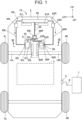
FIG. 1 shows a block diagram of an electrified vehicle including adrive apparatus 20 of a first embodiment; -
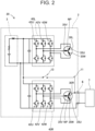
FIG. 2 shows a circuit diagram of thedrive apparatus 20 of the first embodiment; -
FIG. 3 shows a sectional view taken along line III-III inFIG. 1 ; -
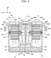
FIG. 4 shows a sectional view similar toFIG. 3 in adrive apparatus 120 of a second embodiment; -
FIG. 5 shows a sectional view similar toFIG. 3 in adrive apparatus 220 of a third embodiment; and -
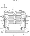
FIG. 6 shows a sectional view similar toFIG. 3 in adrive apparatus 320 of a fourth embodiment. - In a drive apparatus according to a first aspect of the present disclosure, the plurality of rotating electrical machines may include: a first rotating electrical machine; and a second rotating electrical machine. The plurality of electricity conversion apparatuses may include: a first electricity conversion apparatus electrically connected to the first rotating electrical machine; and a second electricity conversion apparatus electrically connected to the second rotating electrical machine. The plurality of refrigerant routes may include: a first refrigerant route configured to cool the first electricity conversion apparatus and the second rotating electrical machine; and a second refrigerant route configured to cool the second electricity conversion apparatus and the first rotating electrical machine. However, in another embodiment, the rotating electrical machines may include three or more rotating electrical machines. In this case, the electricity conversion apparatuses may include three or more electricity conversion apparatuses, and the refrigerant routes may include three or more refrigerant routes.
- The drive apparatus according to the first aspect of the present disclosure may further include: a first oil cooler configured to cool the first rotating electrical machine; and a first oil pump configured to supply oil to the first rotating electrical machine via the first oil cooler. The second refrigerant route may be configured to cool the oil in the first oil cooler.
- According to such a configuration, the first rotating electrical machine can be cooled and the rotation of the first rotating electrical machine can be caused to be smoother by the oil.
- The drive apparatus according to the first aspect of the present disclosure may further include: a second oil cooler configured to cool the second rotating electrical machine; and a second oil pump configured to supply oil to the second rotating electrical machine via the second oil cooler. The first refrigerant route may be configured to cool the oil in the second oil cooler.
- According to such a configuration, the second rotating electrical machine can be cooled and the rotation of the second rotating electrical machine can be caused to be smoother by the oil.
- The drive apparatus according to the first aspect of the present disclosure may further include a casing that accommodates the first rotating electrical machine and the second rotating electrical machine. However, in another embodiment, the drive apparatus may include a first casing that accommodates the first rotating electrical machine and a second casing that accommodates the second rotating electrical machine.
- The drive apparatus according to the first aspect of the present disclosure may further include first cooling equipment in abutment against at least a part of a front surface of a first stator of the first rotating electrical machine. The second refrigerant route may be configured to cool the first rotating electrical machine via the first cooling equipment. Here, "the cooling equipment" is an apparatus including a flow path through which a refrigerant is caused to circulate and is a so-called water jacket, for example.
- According to such a configuration, the first rotating electrical machine can be efficiently cooled by the first cooling equipment.
- The drive apparatus according to the first aspect of the present disclosure may further include second cooling equipment in abutment against at least a part of a front surface of a second stator of the second rotating electrical machine. The first refrigerant route may be configured to cool the second rotating electrical machine via the second cooling equipment.
- According to such a configuration, the second rotating electrical machine can be efficiently cooled by the second cooling equipment.
- The drive apparatus according to the first aspect of the present disclosure may further include: a first oil cooler configured to cool the first rotating electrical machine; and a first oil pump configured to supply oil to the first rotating electrical machine via the first oil cooler. The second refrigerant route may be further configured to cool the oil in the first oil cooler. The first cooling equipment and the first oil cooler may be connected to each other in series in the second refrigerant route.
- According to such a configuration, the first rotating electrical machine can be quickly cooled by the oil and the first cooling equipment.
- The drive apparatus according to the first aspect of the present disclosure may further include: a second oil cooler configured to cool the second rotating electrical machine; and a second oil pump configured to supply oil to the second rotating electrical machine via the second oil cooler. The first refrigerant route may be further configured to cool the oil in the second oil cooler. The second cooling equipment and the second oil cooler may be connected to each other in series in the first refrigerant route.
- According to such a configuration, the second rotating electrical machine can be quickly cooled by the oil and the second cooling equipment.
- In the drive apparatus according to the first aspect of the present disclosure, the drive apparatus may be configured to be mounted on a vehicle. The drive apparatus may configure a charging circuit that supplies a charging current supplied from a power source outside the vehicle to an electricity storage apparatus of the vehicle via a neutral point of the first rotating electrical machine.
- In the drive apparatus described above, only the first rotating electrical machine and the first electricity apparatus operate when the charging current is supplied to the electricity storage apparatus of the vehicle via the neutral point of the first rotating electrical machine. In this case, the first rotating electrical machine and the first electricity apparatus generate heat, and the second rotating electrical machine and the second electricity apparatus do not generate heat. Therefore, the first refrigerant route that cools the second electricity apparatus that is not generating heat can efficiently cool the first rotating electrical machine that generates heat.
- The drive apparatus according to the first aspect of the present disclosure may further include: a first oil cooler configured to cool the first rotating electrical machine; a first oil pump configured to supply oil to the first rotating electrical machine via the first oil cooler; and a control apparatus configured to control the first oil pump. The second refrigerant route may be configured to cool the oil in the first oil cooler. The control apparatus may drive the first oil pump in at least a part of a period of charging time in which the charging current is supplied to the electricity storage apparatus of the vehicle via the neutral point of the first rotating electrical machine.
- According to such a configuration, the first oil pump can supply oil cooled by the first refrigerant route that cools the second electricity apparatus that is not generating heat to the first rotating electrical machine that generates heat during the period of charging time.
- The drive apparatus according to the first aspect of the present disclosure may further include: a second oil cooler configured to cool the second rotating electrical machine; and a second oil pump configured to supply oil to the second rotating electrical machine via the second oil cooler. The first refrigerant route may be configured to cool the oil in the second oil cooler. The control apparatus may stop driving of the second oil pump in at least a part of the period of charging time.
- According to such a configuration, the oil cooled by the second refrigerant route that cools the first electricity apparatus that is generating heat is not supplied to the second rotating electrical machine that is not generating heat during the period of charging time. As a result, the second oil pump can be prevented from being unnecessarily driven.
- In the drive apparatus according to the first aspect of the present disclosure, the drive apparatus may be configured to be mounted on a vehicle. The first rotating electrical machine may be configured to transmit a motive power to a first drive wheel of a pair of left and right drive wheels of the vehicle, and the second rotating electrical machine may be configured to transmit a motive power to a second drive wheel of the pair of left and right drive wheels of the vehicle. However, in another embodiment, the first rotating electrical machine and the second rotating electrical machine may drive both of the pair of left and right drive wheels of the vehicle. The first rotating electrical machine may transmit a motive power to a drive wheel positioned on the front side of the vehicle, and the second rotating electrical machine may transmit a motive power to a drive wheel positioned on the rear side of the vehicle.
-
FIG. 1 shows a block diagram of an electrifiedvehicle 10 including adrive apparatus 20 of a first embodiment seen from above. In the present specification, the front side of the electrified vehicle 10 (in other words, the upper side of the plane of the paper ofFIG. 1 ) may be simply referred to as "front", and the opposite side may be simply referred to as "rear". The left side of the electrified vehicle 10 (in other words, the left side of the plane of the paper ofFIG. 1 ) may be simply referred to as "left", and the opposite side may be simply referred to as "right". The upper side of the electrified vehicle 10 (in other words, the near side of the plane of the paper ofFIG. 1 ) may be simply referred to as "upper", and the opposite side may be simply referred to as "lower". - The electrified
vehicle 10 includes avehicle body 2, abattery pack 3, a pair of left and rightfront wheels rear wheels inlet 6, adrive apparatus 20, aradiator 60, a pair of left andright cooling fans refrigerant route 62R, a secondrefrigerant route 62L, afirst radiator pump 64R, and asecond radiator pump 64L. The electrifiedvehicle 10 travels by driving the pair of left and rightfront wheels drive apparatus 20. "The electrified vehicle" in the present specification includes a rechargeable battery electric vehicle charged by an external power source, a fuel cell electric vehicle of which power source is a fuel cell, and a hybrid electric vehicle also having an engine, for example. The expression of "a pair of left and right" may be simply hereinafter described as "a pair". - The
drive apparatus 20 includes acasing 21, a pair ofelectric motors power transmission mechanisms oil coolers inverters control apparatus 80. - Both of the pair of
electric motors drive apparatus 20 drives the pair offront wheels battery pack 3 to the pair ofelectric motors inverters front wheels vehicle 10. In a modified example, the pair ofrear wheels vehicle 10 or the pair offront wheels rear wheels vehicle 10. - The
casing 21 accommodates the pair ofelectric motors power transmission mechanisms casing 21 is indicated by broken lines, and apparatuses such as the pair ofelectric motors casing 21 are indicated by solid lines inFIG. 1 . The pair ofinverters first inverter 40R positioned on the right side and thesecond inverter 40L positioned on the left side and are disposed on an upper surface of thecasing 21. The pair of motivepower transmission mechanisms power transmission mechanism 50R positioned on the right side and the second motivepower transmission mechanism 50L positioned on the left side. The pair ofelectric motors electric motor 30R positioned on the right side and the secondelectric motor 30L positioned on the left side. The first motivepower transmission mechanism 50R transmits the motive power of the firstelectric motor 30R to aright drive shaft 14R connected to theright front wheel 4R. The first motivepower transmission mechanism 50R has a plurality of gears, bearings, and the like. The first motivepower transmission mechanism 50R functions as a decelerator that decelerates the rotational speed of the firstelectric motor 30R and rotates theright drive shaft 14R, for example. Similarly, the second motivepower transmission mechanism 50L transmits the motive power of the secondelectric motor 30L to aleft drive shaft 14L connected to theleft front wheel 4L. As shown inFIG. 1 , theright drive shaft 14R and theleft drive shaft 14L are separated from each other at the center of the electrifiedvehicle 10 in the left-right direction. Therefore, the pair offront wheels electric motors drive shafts electric motors front wheels - The charging
inlet 6 is disposed on a right side surface of thevehicle body 2. The charginginlet 6 is configured to be connected to an external power source 7 (for example, a charging stand) via anelectricity cable 8. When the charginginlet 6 is connected to theexternal power source 7, the charging electricity of theexternal power source 7 is supplied to thebattery pack 3. - The pair of
oil coolers casing 21. The pair ofoil coolers - The
radiator 60 is disposed on a front end portion of the vehicle body of the electrifiedvehicle 10. Theradiator 60 is an apparatus that performs heat exchange between a refrigerant that circulates through each of therefrigerant route 62R and therefrigerant route 62L and the outside air. The refrigerant is liquid such as an antifreeze liquid or water, for example. Theradiator 60 cools the refrigerant by wind generated by the coolingfans first radiator pump 64R circulates the refrigerant to the firstrefrigerant route 62R. The firstrefrigerant route 62R includes a firstupstream route 66R, afirst midstream route 67R, and a firstdownstream route 68L. Similarly, thesecond radiator pump 64L circulates the refrigerant to the secondrefrigerant route 62L. The secondrefrigerant route 62L includes a secondupstream route 66L, asecond midstream route 67L, and a seconddownstream route 68R. Each of therefrigerant routes route 69. In other words, in this embodiment, a common refrigerant flows in the firstrefrigerant route 62R and the secondrefrigerant route 62L. The mergingroute 69 connects theradiator 60 and each of thedownstream routes - As indicated by a broken-line arrow in
FIG. 1 , the first radiator pump 64R pressure-feeds the refrigerant to the firstupstream route 66R. As a result, the refrigerant reaches thefirst inverter 40R. The refrigerant is supplied to the second oil cooler 22L via thefirst midstream route 67R. The refrigerant that has passed through the second oil cooler 22L returns to theradiator 60 via the firstdownstream route 68L and the mergingroute 69. Similarly, also in the secondrefrigerant route 62L, the refrigerant that is pressure-fed to the secondupstream route 66L by the second radiator pump 64L flows to thesecond inverter 40L, thesecond midstream route 67L, the first oil cooler 22R, the seconddownstream route 68R, the mergingroute 69, and theradiator 60 in the stated order. - With reference to
FIG. 2 , an electric circuit of thedrive apparatus 20 is described. Thedrive apparatus 20 includes anelectricity supply circuit 11 in addition to the pair ofelectric motors inverters electricity supply circuit 11 is a circuit for supplying DC charging electricity supplied from theexternal power source 7 to thebattery pack 3. The firstelectric motor 30R is a three-phase motor including aU-phase coil 35U, a V-phase coil 35V, and a W-phase coil 35W. Thefirst inverter 40R includes aU-phase arm 42U, a V-phase arm 42V, and a W-phase arm 42W. Each of thephase arms first inverter 40R is an electricity conversion apparatus that converts the DC electricity supplied from thebattery pack 3 to three-phase AC electricity suitable for the driving of the firstelectric motor 30R by turning the switching elements of each of thephase arms U-phase coil 35U, the V-phase coil 35V, and the W-phase coil 35W of the firstelectric motor 30R is connected to each other at a neutral point NP. The other end of theU-phase coil 35U is connected to a midpoint of the two switching elements of theU-phase arm 42U, the other end of the V-phase coil 35V is connected to a midpoint of the two switching elements of the V-phase arm 42V, and the W-phase coil 35W is connected to a midpoint of the two switching elements of the W-phase arm 42W. As above, thefirst inverter 40R is electrically connected to the firstelectric motor 30R. - Similarly, the second
electric motor 30L includes theU-phase coil 35U, the V-phase coil 35V, and the W-phase coil 35W, and thesecond inverter 40L includes theU-phase arm 42U, the V-phase arm 42V, and the W-phase arm 42W. Each of thephase arms second inverter 40L is an electricity conversion apparatus that converts the DC electricity supplied from thebattery pack 3 to three-phase AC electricity suitable for the driving of the secondelectric motor 30L by turning the switching elements of each of thephase arms U-phase coil 35U, the V-phase coil 35V, and the W-phase coil 35W is connected to each other at the neutral point NP, the other end of theU-phase coil 35U is connected to a midpoint of the two switching elements of theU-phase arm 42U, the other end of the V-phase coil 35V is connected to a midpoint of the two switching elements of the V-phase arm 42V, and the W-phase coil 35W is connected to a midpoint of the two switching elements of the W-phase arm 42W. As above, thesecond inverter 40L is electrically connected to the secondelectric motor 30L. - In the
electricity supply circuit 11 of this embodiment, one terminal of the charginginlet 6 is connected to a positive electrode of thebattery pack 3 via the neutral point NP of the firstelectric motor 30R and thefirst inverter 40R. Theelectricity supply circuit 11 supplies the charging electricity supplied from theexternal power source 7 to the neutral point NP of the firstelectric motor 30R. The other terminal of the charginginlet 6 is connected to a negative electrode of thebattery pack 3 via thefirst inverter 40R. Theelectricity supply circuit 11 supplies the charging electricity to thebattery pack 3 via the neutral point NP of the firstelectric motor 30R. As a result, the firstelectric motor 30R and thefirst inverter 40R can function as three voltage boosting circuits parallelly connected to each other between the charginginlet 6 and thebattery pack 3. As a result, thedrive apparatus 20 can boost the output voltage of theexternal power source 7 with use of the firstelectric motor 30R and thefirst inverter 40R. As a result, quick charging can be executed even when the output voltage of theexternal power source 7 is lower than the voltage across thebattery pack 3. One terminal of the charginginlet 6 is directly connected to the positive electrode of thebattery pack 3 via aswitch 13. Theelectricity supply circuit 11 can cause the output voltage of theexternal power source 7 to bypass the neutral point NP of the firstelectric motor 30R by turning ON theswitch 13 when the output voltage of theexternal power source 7 is equivalent to the voltage across thebattery pack 3. Although illustration is omitted, theelectricity supply circuit 11 further includes a charging unit including a relay, a capacitor, and the like. The charging unit is connected to the neutral point NP and thefirst inverter 40R. - When the charging
inlet 6 is connected to theexternal power source 7 and theswitch 13 is turned OFF, the charging electricity of theexternal power source 7 is supplied to the neutral point NP of the firstelectric motor 30R. A period of time in which the charging electricity is supplied to thebattery pack 3 via the supply to the neutral point NP of the firstelectric motor 30R may be hereinafter referred to as "a period of charging time". The current flows to thecoils electric motor 30R over the period of charging time. As a result, thecoils electric motor 30R rises. During the period of charging time, the switching elements of each of thephase arms first inverter 40R electrically connected to the firstelectric motor 30R are turned ON and OFF. As a result, the temperature of thefirst inverter 40R rises. Meanwhile, even when the charginginlet 6 is connected to theexternal power source 7, the current does not flow to thecoils electric motor 30L, and hence the temperature of the secondelectric motor 30L does not rise. Therefore, the temperature of thesecond inverter 40L electrically connected to the secondelectric motor 30L does not rise either. - A detailed structure of the
drive apparatus 20 is described with reference toFIG. 3. FIG. 3 is a sectional view of the drive apparatus taken along line III-III inFIG. 1 . Thedrive apparatus 20 further includes a pair ofoil pumps suction pipes discharge pipes casing 21 in addition to the pair ofelectric motors casing 21 includes a dividingwall 26 extending to the lower side at the center in the left-right direction. The dividingwall 26 is a wall that separates a right space and a left space of thecasing 21 from each other. However, the dividingwall 26 does not reach to a bottom surface of thecasing 21. The right space and the left space of thecasing 21 communicate with each other in a lower portion of thecasing 21. The firstelectric motor 30R and the first motivepower transmission mechanism 50R are disposed on the right side of the dividingwall 26. The secondelectric motor 30L and the second motivepower transmission mechanism 50L are disposed on the left side of the dividingwall 26. Thedrive apparatus 20 is configured to be left-right symmetrical about the center of the dividingwall 26, in other words, a center line CL1. Therefore, a configuration positioned on the right side of the center line CL1 of thedrive apparatus 20 is mainly described below. - The first
electric motor 30R includes amotor shaft 33R, arotor 34R, and astator 35R. Themotor shaft 33R passes through therotor 34R and extends in the left-right direction, and is rotatably maintained in thecasing 21 by a pair ofbearings 39R. Themotor shaft 33R extends to the left side so as to exceed a left end of therotor 34R and is connected to the gears of the first motivepower transmission mechanism 50R. When themotor shaft 33R rotates as a result of therotor 34R rotating, the gears of the first motivepower transmission mechanism 50R rotate. Although illustration is omitted, the first motivepower transmission mechanism 50R rotates theright drive shaft 14R (seeFIG. 1 ) via the gears. In other words, the first motivepower transmission mechanism 50R transmits the motive power of the firstelectric motor 30R to theright drive shaft 14R. Themotor shaft 33R has a hollow structure. A plurality of through-holes 38R is formed in a side surface of themotor shaft 33R. The through-holes 38R communicate with the inner space of themotor shaft 33R and the inner space of thecasing 21. InFIG. 1 , only the two through-holes 38R positioned in a right end out of the through-holes 38R are denoted by reference characters, and reference characters of the other through-holes 38R are omitted. - Similarly, the second
electric motor 30L includes amotor shaft 33L, arotor 34L, and astator 35L. Themotor shaft 33L passes through therotor 34L and extends in the left-right direction, and is rotatably maintained in thecasing 21 by a pair ofbearings 39L. The second motivepower transmission mechanism 50L also transmits the motive power of the secondelectric motor 30L to theleft drive shaft 14L via a gear and the like connected to themotor shaft 33L of the secondelectric motor 30L. - As shown in
FIG. 3 ,oil 76 is accumulated in a lower portion of thecasing 21. Thecasing 21 forms a so-called oil sump. The pair ofoil pumps first oil pump 70R positioned on the right side and thesecond oil pump 70L positioned on the left side. Thefirst oil pump 70R is fixed to the dividingwall 26 from the right side. Thefirst oil pump 70R is a pump that supplies theoil 76 to the firstelectric motor 30R. The pair ofsuction pipes first suction pipe 72R positioned on the right side and thesecond suction pipe 72L positioned on the left side. Thefirst suction pipe 72R extends to the upper side from the oil sump, bends to the left side, and is connected to a suction port of thefirst oil pump 70R. The pair ofdischarge pipes first discharge pipe 74R positioned on the right side and thesecond discharge pipe 74L positioned on the left side. Thefirst discharge pipe 74R extends to the upper side from a discharge port of thefirst oil pump 70R. Thefirst discharge pipe 74R bends to the front side (in other words, the far side of the plane of the paper ofFIG. 3 ), passes through a side wall of thecasing 21 on the front side thereof, extends to the upper side along an outer surface of the side wall on the front side, and passes through the inside of the first oil cooler 22R disposed on the side wall on the front side. After thefirst discharge pipe 74R passes through the first oil cooler 22R, thefirst discharge pipe 74R passes through the side wall of thecasing 21 on the front side thereof again, enters the inside of thecasing 21, and is connected to a left end of themotor shaft 33R of the firstelectric motor 30R. Thefirst oil pump 70R supplies theoil 76 to themotor shaft 33R of the firstelectric motor 30R via thefirst suction pipe 72R and thefirst discharge pipe 74R. Theoil 76 supplied to themotor shaft 33R moves to the inner space of thecasing 21 from the inner space of themotor shaft 33R via the through-holes 38R. Theoil 76 falls in the inner space of thecasing 21 and is accumulated in the lower portion of thecasing 21 again. As above, thefirst oil pump 70R circulates theoil 76. Theoil 76 cools the firstelectric motor 30R and causes the rotation of the firstelectric motor 30R to be smoother. Theoil 76 also lubricates the gears of the first motivepower transmission mechanism 50R. As a result, the first motivepower transmission mechanism 50R smoothly rotates. InFIG. 3 to FIG. 6 , the flow of theoil 76 is indicated by solid-line arrows, and the flow of the refrigerant is indicated by broken-line arrows. - Similarly, the
second oil pump 70L is fixed to the dividingwall 26 from the left side. Thesecond oil pump 70L is a pump that supplies theoil 76 to the secondelectric motor 30L via thesecond suction pipe 72L and thesecond discharge pipe 74L. Thesecond discharge pipe 74L passes through the second oil cooler 22L and is connected to a right end of themotor shaft 33L of the secondelectric motor 30L. As a result, theoil 76 is supplied to the secondelectric motor 30L. As indicated by solid-line arrows inFIG. 3 , thesecond oil pump 70L circulates theoil 76. Theoil 76 cools the secondelectric motor 30L and causes the rotation of the secondelectric motor 30L and the second motivepower transmission mechanism 50L to be smoother. As above, in this embodiment, the firstelectric motor 30R and the secondelectric motor 30L are cooled by an oil-cooling cooling system. - The
control apparatus 80 is disposed on the upper side of thefirst inverter 40R. Thecontrol apparatus 80 is a computer that has a CPU and a memory and controls the pair of coolingfans oil pumps control apparatus 80 controls each of the coolingfans pumps control apparatus 80 may be disposed on a side surface of any of the right side, the left side, the front side, and the rear side of thefirst inverter 40R. The number of thecontrol apparatuses 80 is not limited to one, and thecontrol apparatuses 80 may be disposed on both of left and right side surfaces of thefirst inverter 40R, for example. - As described above, the
first discharge pipe 74R passes through the inside of the first oil cooler 22R and is connected to themotor shaft 33R of the firstelectric motor 30R. As described with reference toFIG. 1 , the refrigerant cooled by theradiator 60 circulates to the first oil cooler 22R via the secondrefrigerant route 62L. Therefore, the refrigerant in the first oil cooler 22R cools theoil 76 in thefirst discharge pipe 74R. Theoil 76 absorbs heat from the firstelectric motor 30R. In other words, the secondrefrigerant route 62L cools the firstelectric motor 30R out of the pair ofelectric motors oil 76. - Similarly, the
second discharge pipe 74L passes through the inside of the second oil cooler 22L and is connected to themotor shaft 33L of the secondelectric motor 30L. As described with reference toFIG. 1 , the refrigerant cooled by theradiator 60 circulates to the second oil cooler 22L via the firstrefrigerant route 62R. Therefore, the refrigerant in the second oil cooler 22L cools theoil 76 in thesecond discharge pipe 74L. Theoil 76 absorbs heat from the secondelectric motor 30L. In other words, the firstrefrigerant route 62R cools the secondelectric motor 30L out of the pair ofelectric motors oil 76. - The
first inverter 40R includes a first inverter cooler 41R. One end of the first inverter cooler 41R is connected to the firstupstream route 66R of the firstrefrigerant route 62R, and the other end of the first inverter cooler 41R is connected to thefirst midstream route 67R. Thefirst midstream route 67R is connected to the firstdownstream route 68L (seeFIG. 1 ) via the second oil cooler 22L. The first inverter cooler 41R has a flow path through which the refrigerant is caused to circulate, and the first inverter cooler 41R cools thefirst inverter 40R by circulating the refrigerant. In other words, the firstrefrigerant route 62R cools thefirst inverter 40R out of the pair ofinverters - Similarly, the
second inverter 40L includes a second inverter cooler 41L. One end of the second inverter cooler 41L is connected to the secondupstream route 66L of the secondrefrigerant route 62L, and the other end of the second inverter cooler 41L is connected to thesecond midstream route 67L. Thesecond midstream route 67L is connected to the seconddownstream route 68R (seeFIG. 1 ) via the first oil cooler 22R. The second inverter cooler 41L has a flow path through which the refrigerant is caused to circulate, and the second inverter cooler 41L cools thesecond inverter 40L by circulating the refrigerant. In other words, the secondrefrigerant route 62L cools thesecond inverter 40L out of the pair ofinverters - As shown in
FIG. 3 , thefirst midstream route 67R of the firstrefrigerant route 62R connects the first inverter cooler 41R of thefirst inverter 40R positioned on the right side of the center line CL1 and the second oil cooler 22L positioned on the left side of the center line CL1 to each other. Thesecond midstream route 67L of the secondrefrigerant route 62L connects the second inverter cooler 41L of thesecond inverter 40L positioned on the left side of the center line CL1 and the first oil cooler 22R positioned on the right side of the center line CL1 to each other. Therefore, thefirst midstream route 67R extends to the left side from the right side of the center line CL1 so as to cross the center line CL1, and thesecond midstream route 67L extends to the right side from the left side of the center line CL 1 so as to cross the center line CL1. As a result, each of themidstream routes - As described above, the first
electric motor 30R is electrically connected to thefirst inverter 40R. The firstelectric motor 30R is cooled by the same secondrefrigerant route 62L as thesecond inverter 40L. In other words, the firstelectric motor 30R is electrically connected to thefirst inverter 40R different from thesecond inverter 40L cooled by the samerefrigerant route 62L as the firstelectric motor 30R. - Similarly, the second
electric motor 30L is electrically connected to thesecond inverter 40L. The secondelectric motor 30L is cooled by the same firstrefrigerant route 62R as thefirst inverter 40R. In other words, the secondelectric motor 30L is electrically connected to thesecond inverter 40L different from thefirst inverter 40R cooled by the samerefrigerant route 62R as the secondelectric motor 30L. - The
control apparatus 80 drives the pair of coolingfans first oil pump 70R in accordance with the charginginlet 6 being connected to theexternal power source 7 via theelectricity cable 8 and theswitch 13 being turned OFF. As a result, a refrigerant cooled by the pair of coolingfans refrigerant route 62L during the period of charging time. Theoil 76 cooled by the refrigerant in the first oil cooler 22R is supplied to the firstelectric motor 30R. The secondrefrigerant route 62L supplies a refrigerant to the first oil cooler 22R via the second inverter cooler 41L of thesecond inverter 40L. The refrigerant that has passed through thesecond inverter 40L that is not generating heat is supplied to the first oil cooler 22R, and theoil 76 cooled by the refrigerant cools the firstelectric motor 30R driven during the period of charging time. In other words, in thedrive apparatus 20 of this embodiment, the firstelectric motor 30R and thefirst inverter 40R electrically connected to each other are not cooled by the same secondrefrigerant route 62L. As a result, the necessary cooling amount can be equalized for each of therefrigerant routes drive apparatus 20 can be improved. - The
control apparatus 80 drives thefirst radiator pump 64R and stops the driving of thesecond oil pump 70L during the period of charging time. As a result, thefirst inverter 40R that operates during the period of charging time can be cooled by the refrigerant that circulates in the firstrefrigerant route 62R. Theoil 76 is not supplied to the secondelectric motor 30L during the period of charging time. As described above, during the period of charging time, the secondelectric motor 30L is not driven, and hence the temperature of the secondelectric motor 30L does not rise. As above, in thedrive apparatus 20 of this embodiment, the driving of thesecond oil pump 70L is stopped during the period of charging time, and hence thesecond oil pump 70L can be prevented from being unnecessarily driven to supply theoil 76 to the secondelectric motor 30L that is not driven. - With reference to
FIG. 4 , adrive apparatus 120 of a second embodiment is described. Thedrive apparatus 120 of this embodiment includes a pair ofcooling equipment drive apparatus 20 of the first embodiment. The pair ofcooling equipment first cooling equipment 120R that cools the firstelectric motor 30R, and thesecond cooling equipment 120L that cools the secondelectric motor 30L. In other words, in this embodiment, the firstelectric motor 30R and the secondelectric motor 30L are cooled by an oil-water-cooling cooling system obtained by combining oil cooling and water cooling. Thefirst cooling equipment 120R is in abutment against an outer surface of thestator 35R of the firstelectric motor 30R. Thefirst cooling equipment 120R cools thestator 35R by causing a refrigerant to pass therethrough. Thefirst cooling equipment 120R is connected to a first oil cooler 122R via a second connection pipe 167R of the secondrefrigerant route 62L (seeFIG. 1 ). The refrigerant that has passed through thefirst cooling equipment 120R returns to theradiator 60 via a seconddownstream route 168R and the merging route 69 (seeFIG. 1 ). - Similarly, the
second cooling equipment 120L is in abutment against an outer surface of thestator 35L of the secondelectric motor 30L. Thesecond cooling equipment 120L is connected to a second oil cooler 122L via afirst connection pipe 167L of the firstrefrigerant route 62R (seeFIG. 1 ). The refrigerant that has passed throughsecond cooling equipment 120L returns to theradiator 60 via a firstdownstream route 168L and the merging route 69 (seeFIG. 1 ). - In the
drive apparatus 120 of this embodiment, the firstelectric motor 30R is cooled by the refrigerant in addition to theoil 76. As a result, the firstelectric motor 30R can be quickly cooled by theoil 76 and the refrigerant. - With reference to
FIG. 5 , adrive apparatus 220 of a third embodiment is described. When compared to thedrive apparatus 120 of the second embodiment described above, thedrive apparatus 220 of this embodiment does not include the pair ofoil coolers oil pumps electric motor 30R and the secondelectric motor 30L are cooled by a water-cooling cooling system. Therefore, in thedrive apparatus 220 of this embodiment, the first inverter cooler 41R of thefirst inverter 40R and thesecond cooling equipment 120L are directly connected to each other via afirst midstream route 267R, and the second inverter cooler 41L of thesecond inverter 40L and thefirst cooling equipment 120R are directly connected to each other via asecond midstream route 267L. As with the second embodiment, the refrigerant that has passed through thefirst cooling equipment 120R returns to theradiator 60 via a firstdownstream route 268R and the merging route 69 (seeFIG. 1 ), and the refrigerant that has passed through thesecond cooling equipment 120L returns to theradiator 60 via a seconddownstream route 268L and the merging route 69 (seeFIG. 1 ). - In the
drive apparatus 220 of this embodiment, the oil 76 (seeFIG. 3 ) is not accumulated in the lower portion of the casing. Therefore, in thedrive apparatus 220, afirst casing 221R that accommodates the firstelectric motor 30R and asecond casing 221L that accommodates the secondelectric motor 30L are included. Each of thecasings - With reference to
FIG. 6 , adrive apparatus 320 of the fourth embodiment is described. Thedrive apparatus 320 of this embodiment basically has a configuration similar to that of thedrive apparatus 20 of the first embodiment, but the positions in which each apparatus is disposed are different. In this embodiment, each ofelectric motors casing 321 in the left-right direction. Amotor shaft 333R of the firstelectric motor 330R exceeds a right end of therotor 34R and extends to the right side. Themotor shaft 333R is connected to a first motivepower transmission mechanism 350R positioned on the right side of the firstelectric motor 330R. Similarly, a motor shaft 333L of the secondelectric motor 330L exceeds a left end of therotor 34L and extends to the left side. The motor shaft 333L is connected to a second motivepower transmission mechanism 350L positioned on the left side of the secondelectric motor 330L. - A
first oil pump 370R is disposed on an inner wall of thecasing 321 on the right side thereof, and asecond oil pump 370L is disposed on an inner wall of thecasing 321 on the left side thereof. Afirst oil cooler 322R is disposed on an outer wall of thecasing 321 on the right side thereof, and a second oil cooler 322L is disposed on an outer wall of thecasing 321 on the left side thereof. Thefirst oil cooler 322R accommodates a part of afirst discharge pipe 374R that extends to the upper side along the outer wall of thecasing 321 on the right side thereof. Thefirst oil pump 370R sucks up theoil 76 by afirst suction pipe 372R and supplies theoil 76 to themotor shaft 333R of the firstelectric motor 330R via thefirst discharge pipe 374R. As a result, theoil 76 cooled by the refrigerant in thefirst oil cooler 322R is supplied to the firstelectric motor 330R. Similarly, the second oil cooler 322L accommodates a part of asecond discharge pipe 374L that extends to the upper side along the outer wall of thecasing 321 on the left side thereof. Thesecond oil pump 370L sucks up theoil 76 by asecond suction pipe 372L and supplies theoil 76 to the motor shaft 333L of the secondelectric motor 30L via thesecond discharge pipe 374L. As a result, theoil 76 cooled by the refrigerant in the second oil cooler 322L is supplied to the secondelectric motor 330L. - As shown in
FIG. 6 , the first inverter cooler 41R of thefirst inverter 40R positioned on the right side of the center line CL1 and the second oil cooler 322L positioned on the left side of the center line CL1 are connected to each other by afirst midstream route 367R in this embodiment as well. The second inverter cooler 41L of thesecond inverter 40L positioned on the left side of the center line CL1 and thefirst oil cooler 322R positioned on the right side of the center line CL1 are connected to each other by asecond midstream route 367L. Therefore, each of themidstream routes - Although specific examples of the technology disclosed by the present specification have been described above in detail, those are merely exemplifications and do not limit the scope of claims. The technology described in the scope of claims includes those obtained by variously modifying and changing the specific examples exemplified above. Modified examples of the embodiments described above are listed below.
- In the embodiments described above, the
drive apparatus 20 includes the twoelectric motors inverters refrigerant routes drive apparatus 20 may include three electric motors, three inverters, and three refrigerant routes, for example. In this case, the first electric motor and the first inverter may be electrically connected to each other, the second electric motor and the second inverter may be electrically connected to each other, and a third electric motor and a third inverter may be electrically connected to each other. The first refrigerant route may cool the first inverter and the second electric motor, the second refrigerant route may cool the second inverter and the third electric motor, and a third refrigerant route may cool the third inverter and the first electric motor. In another modified example, thedrive apparatus 20 may include two electric motors that drive the pair offront wheels rear wheels front wheels rear wheels - The
drive apparatus 20 of the first embodiment does not necessarily need to include theelectricity supply circuit 11. In this modified example, thedrive apparatus 20 does not necessarily need to supply the charging electricity to thebattery pack 3 via the neutral point NP of the firstelectric motor 30R. In this modified example, thecontrol apparatus 80 may drive the pair of coolingfans first oil pump 70R when the rotational speed of the firstelectric motor 30R exceeds a predetermined value, for example. For example, the rotational speed of the firstelectric motor 30R that drives theright front wheel 4R may exceed the predetermined value when the electrifiedvehicle 10 travels a road that curves to the left side. In this modified example, one electric motor of which rotational speed is high can be efficiently cooled with use of a refrigerant that has cooled an inverter electrically connected to another electric motor of which rotational speed is low. - The
drive apparatus 20 of the first embodiment includes the twooil pumps drive apparatus 20 may include one oil pump in this modified example. In this modified example, theoil 76 may be supplied to the twoelectric motors - The
control apparatus 80 does not necessarily need to stop thesecond oil pump 70L during the period of charging time. In this modified example, thecontrol apparatus 80 may drive the pair of coolingfans oil pumps control apparatus 80 may drive the pair of coolingfans first oil pump 70R when the temperature of the firstelectric motor 30R exceeds a predetermined temperature during the period of charging time. - The technical elements described in the present specification or the drawings exhibit a technical utility by itself or by various combinations, and are not limited to the combinations described in the claims as originally filed. The technology exemplified in the present specification or the drawings may achieve a plurality of objects at the same time, and has a technical utility by achievement of one of those objects itself.
Claims (13)
- A drive apparatus (20; 120; 220; 320), comprising:a plurality of rotating electrical machines (30R, 30L; 330R, 330L);a plurality of electricity conversion apparatuses (40R, 40L); anda plurality of refrigerant routes (62R, 62L) provided to be parallel to each other and configured to cool the rotating electrical machines (30R, 30L; 330R, 330L) and the electricity conversion apparatuses (40R, 40L), wherein:each of the electricity conversion apparatuses (40R, 40L) is electrically connected to at least one of the rotating electrical machines (30R, 30L; 330R, 330L);each of the refrigerant routes (62R, 62L) is configured to cool at least one of the electricity conversion apparatuses (40R, 40L) and at least one of the rotating electrical machines (30R, 30L; 330R, 330L); andeach of the rotating electrical machines (30R, 30L; 330R, 330L) is electrically connected to an electricity conversion apparatus (40R, 40L) different from the at least one electricity conversion apparatus (40R, 40L) cooled by the same refrigerant route (62R, 62L) as the rotating electrical machine (30R, 30L; 330R, 330L) itself.
- The drive apparatus (20; 120; 220; 320) according to claim 1, wherein:the rotating electrical machines (30R, 30L; 330R, 330L) include:a first rotating electrical machine (30R; 330R); anda second rotating electrical machine (30L; 330L);the electricity conversion apparatuses (40R, 40L) include:a first electricity conversion apparatus (40R) electrically connected to the first rotating electrical machine (30R; 330R); anda second electricity conversion apparatus (40L) electrically connected to the second rotating electrical machine (30L; 330L); andthe refrigerant routes (62R, 62L) include:a first refrigerant route (62R) configured to cool the first electricity conversion apparatus (40R) and the second rotating electrical machine (30L; 330L); anda second refrigerant route (62L) configured to cool the second electricity conversion apparatus (40L) and the first rotating electrical machine (30R; 330R).
- The drive apparatus (20; 120; 320) according to claim 2, further comprising:a first oil cooler (22R; 122R; 322R) configured to cool the first rotating electrical machine (30R; 330R); anda first oil pump (70R; 370R) configured to supply oil to the first rotating electrical machine (30R; 330R) via the first oil cooler (22R; 122R; 322R), wherein the second refrigerant route (62L) is configured to cool the oil in the first oil cooler (22R; 122R; 322R).
- The drive apparatus (20; 120; 320) according to claim 3, further comprising:a second oil cooler (22L; 122L; 322L) configured to cool the second rotating electrical machine (30L; 330L); anda second oil pump (70L; 370L) configured to supply oil to the second rotating electrical machine (30L; 330L) via the second oil cooler (22L; 122L; 322L), wherein the first refrigerant route (62R) is configured to cool the oil in the second oil cooler (22L; 122L; 322L).
- The drive apparatus (20; 120; 320) according to claim 2, further comprising a casing (21; 321) that accommodates the first rotating electrical machine (30R; 330R) and the second rotating electrical machine (30L; 330L).
- The drive apparatus (120; 220) according to claim 2, further comprising first cooling equipment (120R) in abutment against at least a part of a front surface of a first stator (35R) of the first rotating electrical machine (30R), wherein the second refrigerant route (62L) is configured to cool the first rotating electrical machine (30R) via the first cooling equipment (120R).
- The drive apparatus (120; 220) according to claim 6, further comprising second cooling equipment (120L) in abutment against at least a part of a front surface of a second stator (35L) of the second rotating electrical machine (30L), wherein the first refrigerant route (62R) is configured to cool the second rotating electrical machine (30L) via the second cooling equipment (120L).
- The drive apparatus (120) according to claim 6, further comprising:a first oil cooler (122R) configured to cool the first rotating electrical machine (30R); anda first oil pump (70R) configured to supply oil to the first rotating electrical machine (30R) via the first oil cooler (122R), wherein:the second refrigerant route (62L) is further configured to cool the oil in the first oil cooler (122R); andthe first cooling equipment (120R) and the first oil cooler (122R) are connected to each other in series in the second refrigerant route (62L).
- The drive apparatus (120) according to claim 7, further comprising:a second oil cooler (122L) configured to cool the second rotating electrical machine (30L); anda second oil pump (70L) configured to supply oil to the second rotating electrical machine (30L) via the second oil cooler (122L), wherein:the first refrigerant route (62R) is further configured to cool the oil in the second oil cooler (122L); andthe second cooling equipment (120L) and the second oil cooler (122L) are connected to each other in series in the first refrigerant route (62R).
- The drive apparatus (20; 120; 220; 320) according to claim 2, wherein the drive apparatus (20; 120; 220; 320) is configured to be mounted on a vehicle (10), and configures a charging circuit (11) that supplies a charging current supplied from a power source (7) outside the vehicle (10) to an electricity storage apparatus (3) of the vehicle (10) via a neutral point (NP) of the first rotating electrical machine (30R; 330R).
- The drive apparatus (20; 120; 320) according to claim 10, further comprising:a first oil cooler (22R; 122R; 322R) configured to cool the first rotating electrical machine (30R; 330R);a first oil pump (70R; 370R) configured to supply oil to the first rotating electrical machine (30R; 330R) via the first oil cooler (22R; 122R; 322R); anda control apparatus (80) configured to control the first oil pump (70R; 370R), wherein:the second refrigerant route (62L) is configured to cool the oil in the first oil cooler (22R; 122R; 322R); andthe control apparatus (80) drives the first oil pump (70R; 370R) in at least a part of a period of charging time in which the charging current is supplied to the electricity storage apparatus (3) of the vehicle (10) via the neutral point (NP) of the first rotating electrical machine (30R; 330R).
- The drive apparatus (20; 120; 320) according to claim 11, further comprising:a second oil cooler (22L; 122L; 322L) configured to cool the second rotating electrical machine (30L; 330L); anda second oil pump (70L; 370L) configured to supply oil to the second rotating electrical machine (30L; 330R) via the second oil cooler (22L; 122L; 322L), wherein:the first refrigerant route (62R) is configured to cool the oil in the second oil cooler (22L; 122L; 322L); andthe control apparatus (80) stops driving of the second oil pump (70L; 370L) in at least a part of the period of charging time.
- The drive apparatus (20; 120; 220; 320) according to claim 2, wherein:the drive apparatus (20; 120; 220; 320) is configured to be mounted on a vehicle (10);the first rotating electrical machine (30R; 330R) is configured to transmit a motive power to a first drive wheel (4R; 5R; 4R, 5R) of a pair of left and right drive wheels (4R, 4L; 5R, 5L; 4R, 5R, 4L, 5L) of the vehicle (10); andthe second rotating electrical machine (30L; 330L) is configured to transmit a motive power to a second drive wheel (4L; 5L; 4L, 5L) of the pair of left and right drive wheels (4R, 4L; 5R, 5L; 4R, 5R, 4L, 5L) of the vehicle (10).
Applications Claiming Priority (1)
| Application Number | Priority Date | Filing Date | Title |
|---|---|---|---|
| JP2023218479A JP2025101557A (en) | 2023-12-25 | 2023-12-25 | Drive unit |
Publications (1)
| Publication Number | Publication Date |
|---|---|
| EP4582293A1 true EP4582293A1 (en) | 2025-07-09 |
Family
ID=93926749
Family Applications (1)
| Application Number | Title | Priority Date | Filing Date |
|---|---|---|---|
| EP24221679.4A Pending EP4582293A1 (en) | 2023-12-25 | 2024-12-19 | Drive apparatus |
Country Status (5)
| Country | Link |
|---|---|
| US (1) | US20250211063A1 (en) |
| EP (1) | EP4582293A1 (en) |
| JP (1) | JP2025101557A (en) |
| KR (1) | KR20250099652A (en) |
| CN (1) | CN120222716A (en) |
Citations (5)
| Publication number | Priority date | Publication date | Assignee | Title |
|---|---|---|---|---|
| JP2018121429A (en) | 2017-01-25 | 2018-08-02 | Ntn株式会社 | Electric automobile |
| US20190291570A1 (en) * | 2018-03-23 | 2019-09-26 | Sf Motors, Inc. | Dual loop liquid cooling of integrated electric drivetrain |
| DE102020215827A1 (en) * | 2019-12-16 | 2021-06-17 | Mahle Filter Systems Japan Corporation | Cooling device for inverters |
| WO2022131007A1 (en) * | 2020-12-15 | 2022-06-23 | 株式会社デンソー | Cooling system |
| US20230182560A1 (en) * | 2021-12-10 | 2023-06-15 | Hyundai Motor Company | Cooling system for vehicle driven by in-wheel motor |
Family Cites Families (3)
| Publication number | Priority date | Publication date | Assignee | Title |
|---|---|---|---|---|
| JP6327174B2 (en) * | 2015-02-20 | 2018-05-23 | 株式会社安川電機 | Drive device |
| JP6733503B2 (en) * | 2016-11-04 | 2020-08-05 | トヨタ自動車株式会社 | Vehicle cooling system |
| US10396631B2 (en) * | 2017-10-31 | 2019-08-27 | Nio Usa, Inc. | Dual inverter and electric motor split-flow cooling system |
-
2023
- 2023-12-25 JP JP2023218479A patent/JP2025101557A/en active Pending
-
2024
- 2024-12-13 CN CN202411838302.6A patent/CN120222716A/en active Pending
- 2024-12-16 US US18/981,860 patent/US20250211063A1/en active Pending
- 2024-12-19 EP EP24221679.4A patent/EP4582293A1/en active Pending
- 2024-12-20 KR KR1020240192523A patent/KR20250099652A/en active Pending
Patent Citations (5)
| Publication number | Priority date | Publication date | Assignee | Title |
|---|---|---|---|---|
| JP2018121429A (en) | 2017-01-25 | 2018-08-02 | Ntn株式会社 | Electric automobile |
| US20190291570A1 (en) * | 2018-03-23 | 2019-09-26 | Sf Motors, Inc. | Dual loop liquid cooling of integrated electric drivetrain |
| DE102020215827A1 (en) * | 2019-12-16 | 2021-06-17 | Mahle Filter Systems Japan Corporation | Cooling device for inverters |
| WO2022131007A1 (en) * | 2020-12-15 | 2022-06-23 | 株式会社デンソー | Cooling system |
| US20230182560A1 (en) * | 2021-12-10 | 2023-06-15 | Hyundai Motor Company | Cooling system for vehicle driven by in-wheel motor |
Also Published As
| Publication number | Publication date |
|---|---|
| CN120222716A (en) | 2025-06-27 |
| JP2025101557A (en) | 2025-07-07 |
| KR20250099652A (en) | 2025-07-02 |
| US20250211063A1 (en) | 2025-06-26 |
Similar Documents
| Publication | Publication Date | Title |
|---|---|---|
| CN105102252B (en) | drive unit for vehicle | |
| US12294275B2 (en) | Vehicle drive device | |
| JP4645602B2 (en) | Vehicle drive device | |
| JP2007166803A (en) | Vehicle drive device | |
| EP4027494B1 (en) | Drive unit for electric vehicle | |
| EP3471242B1 (en) | Cooling structure for rotary electric machine | |
| JP4289340B2 (en) | Drive device for hybrid vehicle | |
| JP7740365B2 (en) | Vehicle drive unit | |
| JP7831493B2 (en) | Vehicle drive systems | |
| JP6070444B2 (en) | Vehicle drive device | |
| EP4582293A1 (en) | Drive apparatus | |
| JP7552934B2 (en) | Vehicle drive device | |
| CN119283609A (en) | Electric Vehicles | |
| CN120659726A (en) | Electric driving device for vehicle | |
| JP2024134948A (en) | Electric Vehicles | |
| CN117955294A (en) | Electric drive system and vehicle | |
| JP7816337B2 (en) | Drive unit | |
| EP4578709A1 (en) | Drive device | |
| CN119502657B (en) | Power assembly, double-motor power assembly and electric vehicle | |
| JP7816205B2 (en) | Drive unit | |
| JP2024112686A (en) | Drive unit | |
| JP7841444B2 (en) | Motors and motor systems | |
| JP2024134944A (en) | Busbar Unit |
Legal Events
| Date | Code | Title | Description |
|---|---|---|---|
| PUAI | Public reference made under article 153(3) epc to a published international application that has entered the european phase |
Free format text: ORIGINAL CODE: 0009012 |
|
| STAA | Information on the status of an ep patent application or granted ep patent |
Free format text: STATUS: REQUEST FOR EXAMINATION WAS MADE |
|
| 17P | Request for examination filed |
Effective date: 20250103 |
|
| AK | Designated contracting states |
Kind code of ref document: A1 Designated state(s): AL AT BE BG CH CY CZ DE DK EE ES FI FR GB GR HR HU IE IS IT LI LT LU LV MC ME MK MT NL NO PL PT RO RS SE SI SK SM TR |
|
| GRAP | Despatch of communication of intention to grant a patent |
Free format text: ORIGINAL CODE: EPIDOSNIGR1 |
|
| STAA | Information on the status of an ep patent application or granted ep patent |
Free format text: STATUS: GRANT OF PATENT IS INTENDED |
|
| INTG | Intention to grant announced |
Effective date: 20260120 |
|
| GRAS | Grant fee paid |
Free format text: ORIGINAL CODE: EPIDOSNIGR3 |
|
| GRAA | (expected) grant |
Free format text: ORIGINAL CODE: 0009210 |
|
| STAA | Information on the status of an ep patent application or granted ep patent |
Free format text: STATUS: THE PATENT HAS BEEN GRANTED |