EP4582218A1 - Elektrowerkzeug - Google Patents
Elektrowerkzeug Download PDFInfo
- Publication number
- EP4582218A1 EP4582218A1 EP23859918.7A EP23859918A EP4582218A1 EP 4582218 A1 EP4582218 A1 EP 4582218A1 EP 23859918 A EP23859918 A EP 23859918A EP 4582218 A1 EP4582218 A1 EP 4582218A1
- Authority
- EP
- European Patent Office
- Prior art keywords
- bearing
- output shaft
- motor
- electric tool
- transmission mechanism
- Prior art date
- Legal status (The legal status is an assumption and is not a legal conclusion. Google has not performed a legal analysis and makes no representation as to the accuracy of the status listed.)
- Pending
Links
Images






Classifications
-
- B—PERFORMING OPERATIONS; TRANSPORTING
- B25—HAND TOOLS; PORTABLE POWER-DRIVEN TOOLS; MANIPULATORS
- B25B—TOOLS OR BENCH DEVICES NOT OTHERWISE PROVIDED FOR, FOR FASTENING, CONNECTING, DISENGAGING, OR HOLDING
- B25B23/00—Details of, or accessories for, spanners, wrenches, screwdrivers
- B25B23/14—Arrangement of torque limiters or torque indicators in wrenches or screwdrivers
- B25B23/147—Arrangement of torque limiters or torque indicators in wrenches or screwdrivers specially adapted for electrically operated wrenches or screwdrivers
-
- B—PERFORMING OPERATIONS; TRANSPORTING
- B25—HAND TOOLS; PORTABLE POWER-DRIVEN TOOLS; MANIPULATORS
- B25B—TOOLS OR BENCH DEVICES NOT OTHERWISE PROVIDED FOR, FOR FASTENING, CONNECTING, DISENGAGING, OR HOLDING
- B25B21/00—Portable power-driven screw or nut setting or loosening tools; Attachments for drilling apparatus serving the same purpose
-
- B—PERFORMING OPERATIONS; TRANSPORTING
- B25—HAND TOOLS; PORTABLE POWER-DRIVEN TOOLS; MANIPULATORS
- B25F—COMBINATION OR MULTI-PURPOSE TOOLS NOT OTHERWISE PROVIDED FOR; DETAILS OR COMPONENTS OF PORTABLE POWER-DRIVEN TOOLS NOT PARTICULARLY RELATED TO THE OPERATIONS PERFORMED AND NOT OTHERWISE PROVIDED FOR
- B25F5/00—Details or components of portable power-driven tools not particularly related to the operations performed and not otherwise provided for
- B25F5/001—Gearings, speed selectors, clutches or the like specially adapted for rotary tools
-
- B—PERFORMING OPERATIONS; TRANSPORTING
- B25—HAND TOOLS; PORTABLE POWER-DRIVEN TOOLS; MANIPULATORS
- B25F—COMBINATION OR MULTI-PURPOSE TOOLS NOT OTHERWISE PROVIDED FOR; DETAILS OR COMPONENTS OF PORTABLE POWER-DRIVEN TOOLS NOT PARTICULARLY RELATED TO THE OPERATIONS PERFORMED AND NOT OTHERWISE PROVIDED FOR
- B25F5/00—Details or components of portable power-driven tools not particularly related to the operations performed and not otherwise provided for
- B25F5/02—Construction of casings, bodies or handles
Definitions
- the present disclosure generally relates to an electric tool, and more particularly relates to an electric tool including a motor.
- Patent Literature 1 discloses a portable electric tool.
- the portable electric tool includes: an electric motor serving as a drive source; a speed reducer mechanism for transmitting rotational power generated by the electric motor; a driving unit for transmitting the rotational power from the speed reducer mechanism to a tip tool; a barrel shell that houses a bearing for holding the driving unit rotatably; and a grip shell that houses a switch unit for controlling the supply of electric power to the electric motor.
- An electric tool includes a motor, an output shaft, a transmission mechanism, a first bearing and a second bearing, and a cover.
- the output shaft is to be coupled to a tip tool.
- the transmission mechanism is engaged with the output shaft to transmit torque generated by the motor to the output shaft.
- the first bearing and the second bearing are arranged to support the output shaft rotatably.
- the cover houses the motor, the transmission mechanism, the first bearing, and the second bearing.
- the first bearing is interposed between the second bearing and the tip tool.
- the second bearing is arranged to be in contact with the transmission mechanism and the cover in a region where the transmission mechanism is engaged with the output shaft.
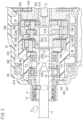
- An electric tool 1 includes a motor 2, an output shaft 6, a transmission mechanism 3, a first bearing 8A and a second bearing 8B, and a cover 10B as shown in FIG. 1 .
- the output shaft 6 is to be coupled to a tip tool 11 such as a screwdriver bit for use to fasten a fastening member such as a screw or a bolt.
- a tip tool 11 such as a screwdriver bit for use to fasten a fastening member such as a screw or a bolt.
- the transmission mechanism 3 is engaged with the output shaft 6 and transmits torque generated by the motor 2 to the output shaft 6.
- the first bearing 8A and the second bearing 8B support the output shaft 6 rotatably.
- the cover 10B houses the motor 2, the transmission mechanism 3, the first bearing 8A, and the second bearing 8B.
- the first bearing 8A is interposed between the second bearing 8B and the tip tool 11.
- the second bearing 8B is arranged to be in contact with the transmission mechanism 3 and the cover 10B in a region where the transmission mechanism 3 is engaged with the output shaft 6.
- the output shaft 6 is supported, via the transmission mechanism 3, by not only the second bearing 8B but also the cover 10B in contact with the second bearing 8B as shown in FIG. 9 .
- This allows, when force (radial load) F3 is applied to the output shaft 6 in a direction intersecting with the axis of the output shaft 6, the cover 10B to receive the force F3, thus reducing the degree of eccentricity of the output shaft 6 and thereby contributing to stabilizing the operations being performed by the electric tool 1.
- the direction pointing from the motor 2 toward the output shaft 6 along the axis of the output shaft 6 is herein defined to be a "forward direction” and the direction pointing from the output shaft 6 toward the motor 2 along the axis of the output shaft 6 is herein defined to be a "backward direction” as shown in FIG. 1 and other drawings.
- the direction pointing from a grip 102 toward a barrel 101 perpendicularly to the forward/backward directions is herein defined to be an "upward direction” and the direction pointing from the barrel 101 toward the grip 102 perpendicularly to the forward/backward directions is herein defined to be a "downward direction.”
- the electric tool 1 is a portable electric tool (such as a screwdriver bit) which may be gripped by the worker with one of his or her hands.
- the electric tool 1 includes the motor 2, the output shaft 6, the transmission mechanism 3, a bearing (first bearing) 8A, the cover 10B, a regulating structure H0, a housing 10A, an inertial body 4, a switch 13, a control unit 7, and a storage unit 9.
- the electric tool 1 further includes the second bearing 8B housed in the cover 10B to support the output shaft 6 rotatably.
- the output shaft 6 includes a second holding portion H2 arranged in contact with at least a part of the second end surface S2.
- the second holding portion H2 may be, for example, a ringlike portion protruding outward from the surface of the output shaft 6.
- the second end surface S2 and the second holding portion H2 are in contact with each other in the forward/backward direction.
- the second holding portion H2 does not have to be a ringlike portion but may also be a portion in the shape of a projection, for example.
- the second bearing 8B is housed inside the cover 10B backward of the first bearing 8A and the first holding portion H1 and supports the output shaft 6 rotatably.
- the tip tool 11 is attached to the output shaft 6 via the chuck 12 forward of the first bearing 8A.
- the first bearing 8A is interposed between the second bearing 8B and the tip tool 11.
- the second bearing 8B may be, for example, a hollow circular columnar ball bearing.
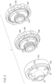
- the second bearing 8B includes an outer ring 81B, an inner ring 82B, and spherical rolling elements as shown in FIG. 3 .
- the second bearing 8B makes the inner ring 82B support the cylindrical portion 37 of the third carrier 34C with the outer ring 81B held by the cover 10B. In this case, the cylindrical portion 37 is engaged with the output shaft 6.
- the second bearing 8B is arranged to be in contact with the third carrier 34C and the cover 10B in a part where the third carrier 34C is engaged with the output shaft 6. That is to say, the second bearing 8B is arranged to be in contact with the transmission mechanism 3 and the cover 10B in the part where the transmission mechanism 3 is engaged with the output shaft 6.
- the switch 13 protrudes forward from the grip 102 as shown in FIG. 1 .
- the switch 13 is an operating member that accepts an operating command entered by the user to control the motor 2. Specifically, the worker may turn ON and OFF the motor 2 by pulling the switch 13.
- the rotational velocity of the drive shaft 21 may also be adjusted depending on how deep the switch 13 is pulled. For example, the deeper the switch 13 is pulled, the higher the rotational velocity of the drive shaft 21 becomes.
- the storage unit 9 may be implemented as, for example, a read-only memory (ROM), a random-access memory (RAM), or an electrically erasable programmable read-only memory (EEPROM).
- the storage unit 9 stores a control program to be executed by the control unit 7.
- the storage unit 9 also stores a preset value of the fastening torque (i.e., preset torque value).
- the control unit 7 includes an acquirer 71 and a driving controller 72 as shown in FIG. 4 .
- the acquirer 71 and the driving controller 72 do not necessarily have a substantive configuration but only represent functions to be performed by the control unit 7.
- the acquirer 71 acquires, based on the amount of current flowing through the motor 2, a torque value associated with the output torque provided by the tip tool 11.
- the driving controller 72 controls the motor 2.
- the driving controller 72 may control the motor 2 by vector control, for example.
- the driving controller 72 breaks down a motor current, which is a current to be supplied to the motor 2, into a torque current (q-axis current) that generates torque and an excitation current (d-axis current) that generates a magnetic flux and controls these current components independently of each other.
- a motor current which is a current to be supplied to the motor 2
- q-axis current torque current
- d-axis current excitation current
- the driving controller 72 controls the motor 2 to make the torque value measured by the acquirer 71 equal to the preset torque value stored in advance in the storage unit 9. For example, when the difference between the torque value detected by the acquirer 71 and the preset torque value falls within a predetermined tolerance range (e.g., ⁇ 20% of the preset torque value), the driving controller 72 controls the motor 2 to stop rotating the drive shaft 21.
- a predetermined tolerance range e.g., ⁇ 20% of the preset torque value
- the electric tool 1 is used to perform operations with a tip tool pressed against a work target (such as a screw).
- a thrust load F1 is applied as reaction force from the work target to the tip tool 11 and the output shaft 6, which is coupled to the tip tool 11, in the direction aligned with the axis of the output shaft 6 (i.e., in the forward/backward direction) as shown in FIG. 3 .
- the electric tool 1 has the regulating structure H0 (including the first holding portion H1 and the second holding portion H2) that sandwiches the first bearing 8A in the forward/backward direction.
- the thrust load F1 applied in the axial direction to the output shaft 6 is transmitted from the second holding portion H2 provided for the output shaft 6 to the second end surface S2 of the first bearing 8A. Then, the thrust load F1 transmitted to the second end surface S2 is transmitted as force F2 from the first end surface S1 to the first holding portion H1 provided for the cover 10B. That is to say, the thrust load F1 applied to the output shaft 6 is broken down into the force F2. This may reduce the degree of eccentricity of the output shaft 6, thus contributing to stabilizing the operations being performed by the electric tool 1.
- the transmission mechanism 3 is housed inside the cover 10B to prevent the force applied in the forward/backward direction from being transmitted from the cover 10B.
- the thrust load F1 transmitted to the first holding portion H1 is not transmitted to the third carrier 34C of the transmission mechanism 3.
- the output shaft 6 and the engagement hole 38 of the third carrier 34C are engaged with each other by gap fitting, and therefore, the thrust load F1 applied to the output shaft 6 is not transmitted to the cylindrical portion 37 of the third carrier 34C.
- the first bearing 8A and the third carrier 34C are spaced from each other in the forward/backward direction.
- the torque value may be stabilized by preventing the acquirer 71 from detecting a variation in the amount of current flowing through the motor 2 due to the frictional force produced in the transmission mechanism 3.
- the regulating structure H0 achieves the advantage of stabilizing the torque value.
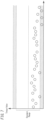
- the ordinate indicates a torque value in a situation where the thrust load F1 is applied to the output shaft in an electric tool according to a comparative example without regulating structure H0.
- the ordinate indicates a torque value in a situation where the thrust load F1 is applied to the output shaft in the electric tool 1 according to this embodiment with the regulating structure H0.
- the torque value is less dispersed in the electric tool 1 according to this embodiment than in the electric tool according to the comparative example.
- every torque value shown in FIG. 8 falls within a standard range.
- the electric tool 1 while the electric tool 1 according to this embodiment is being used to perform operations on a work target (such as a screw), force (a radial load) F3 (refer to FIG. 9 ) may be applied in a direction intersecting with the axis of the output shaft 6 to the tip tool 11 and the output shaft 6 due to, for example, the movement of the worker who is holding the electric tool 1.
- the electric tool 1 includes the second bearing 8B arranged to be in contact with the transmission mechanism 3 and the cover 10B in a region where the transmission mechanism 3 is engaged with the output shaft 6.
- the second bearing 8B is arranged such that at least a part of the output shaft 6, at least a part of the third carrier 34C, and at least a part of the second bearing 8B overlap with each other when viewed in a direction intersecting with the axis of the output shaft 6. That is to say, the output shaft 6 is supported by the second bearing 8B via the third carrier 34C and is further supported by the cover 10B in contact with the second bearing 8B.
- the second bearing 8B achieves the advantage of stabilizing the torque value.
- the ordinate indicates a torque value in a situation where the radial load F3 is applied to the output shaft in an electric tool according to a second comparative example without the second bearing 8B.
- the ordinate indicates a torque value in a situation where the radial load F3 is applied to the output shaft in the electric tool 1 according to this embodiment with the second bearing 8B.
- the torque value is less dispersed in the electric tool 1 according to this embodiment than in the electric tool according to the second comparative example.
- every torque value shown in FIG. 11 falls within a standard range.
- the electric tool 1 contributes to stabilizing the operations being performed.
- the electric tool 1 includes a computer system in its control unit 7.
- the computer system includes a processor and a memory as principal hardware components thereof.
- the computer system performs the functions of the control unit 7 according to the present disclosure by making the processor execute a program stored in the memory of the computer system.
- the program may be stored in advance in the memory of the computer system. Alternatively, the program may also be downloaded through a telecommunications line or be distributed after having been recorded in some non-transitory storage medium such as a memory card, an optical disc, or a hard disk drive, any of which is readable for the computer system.
- the processor of the computer system may be made up of a single or a plurality of electronic circuits including a semiconductor integrated circuit (IC) or a large-scale integrated circuit (LSI).
- IC semiconductor integrated circuit
- LSI large-scale integrated circuit
- the "integrated circuit” such as an IC or an LSI is called by a different name depending on the degree of integration thereof.
- the integrated circuits such as an IC or an LSI include integrated circuits called a "system LSI,” a “very-large-scale integrated circuit (VLSI),” and an “ultra-large-scale integrated circuit (ULSI).”
- a field-programmable gate array (FPGA) to be programmed after an LSI has been fabricated or a reconfigurable logic device allowing the connections or circuit sections inside of an LSI to be reconfigured may also be adopted as the processor.
- Those electronic circuits may be either integrated together on a single chip or distributed on multiple chips, whichever is appropriate.
- the "computer system” includes a microcontroller including one or more processors and one or more memories.
- the microcontroller may also be implemented as a single or a plurality of electronic circuits including a semiconductor integrated circuit or a large-scale integrated circuit.
- a socket may also be attached as a tip tool 11 instead of the screwdriver bit.
- the electric tool 1 does not have to be configured to use the battery pack 14 as a power supply but may also be configured to use an AC power supply (commercial power supply) as its power supply.
- an electric tool (1) includes a motor (2), an output shaft (6), a transmission mechanism (3), a first bearing (8A) and a second bearing (8B), and a cover (10B).
- the output shaft (6) is to be coupled to a tip tool (11).
- the transmission mechanism (3) is engaged with the output shaft (6) to transmit torque generated by the motor (2) to the output shaft (6).
- the first bearing (8A) and the second bearing (8B) are arranged to support the output shaft (6) rotatably.
- the cover (10B) houses the motor (2), the transmission mechanism (3), the first bearing (8A), and the second bearing (8B).
- the first bearing (8A) is interposed between the second bearing (8B) and the tip tool (11).
- the second bearing (8B) is arranged to be in contact with the transmission mechanism (3) and the cover (10B) in a region where the transmission mechanism (3) is engaged with the output shaft (6).
- the output shaft (6) is supported, via the transmission mechanism (3), by not only the second bearing (8B) but also the cover (10B) in contact with the second bearing (8B). This may reduce, when force (F3) is applied to the output shaft (6) in a direction intersecting with the axis of the output shaft (6), the degree of eccentricity of the output shaft (6), thus contributing to stabilizing the operations being performed by the electric tool (1).
- An electric tool (1) which may be implemented in conjunction with the first aspect, further includes an acquirer (71) which acquires, based on a current flowing through the motor (2), a torque value associated with output torque provided by the tip tool (11).
- This aspect allows operations to be performed with appropriate torque on a work target by comparing a torque value acquired by the acquirer (71) with a preset torque value.
- the transmission mechanism (3) includes a sun gear (31C), a plurality of planetary gears (32C), an internal gear (33C), and a carrier (34C).
- the sun gear (31C) turns with motive power supplied from the motor (2).
- the plurality of planetary gears (32C) are arranged around the sun gear (31C) to mesh with the sun gear (31C).
- the internal gear (33C) is arranged around the plurality of planetary gears (32C) to mesh with the plurality of planetary gears (32C).
- the carrier (34C) is engaged with the output shaft (6) to support each of the plurality of planetary gears (32C) rotatably.
- the second bearing (8B) is arranged to be in contact with the carrier (34C) and the cover (10B) in a region where the carrier (34C) is engaged with the output shaft (6).
- the output shaft (6) is supported, via the carrier (34C), by not only the second bearing (8B) but also the cover (10B) in contact with the second bearing (8B). This may reduce, when force (F3) is applied to the output shaft (6) in a direction intersecting with the axis of the output shaft (6), the degree of eccentricity of the output shaft (6), thus contributing to stabilizing the operations being performed by the electric tool (1).
- At least a part of the output shaft (6), at least a part of the carrier (34C), and at least a part of the second bearing (8B) are arranged to overlap with each other when viewed in a direction intersecting with an axis of the output shaft (6).
- the output shaft (6) is supported, via the carrier (34C), by not only the second bearing (8B) but also the cover (10B) in contact with the second bearing (8B). This may reduce, when force (F3) is applied to the output shaft (6) in a direction intersecting with the axis of the output shaft (6), the degree of eccentricity of the output shaft (6), thus contributing to stabilizing the operations being performed by the electric tool (1).
- constituent elements according to the second to fourth aspects are not essential constituent elements for the electric tool (1) but may be omitted as appropriate.
Landscapes
- Engineering & Computer Science (AREA)
- Mechanical Engineering (AREA)
- Connection Of Motors, Electrical Generators, Mechanical Devices, And The Like (AREA)
- Portable Power Tools In General (AREA)
Applications Claiming Priority (2)
| Application Number | Priority Date | Filing Date | Title |
|---|---|---|---|
| JP2022138767A JP2024034505A (ja) | 2022-08-31 | 2022-08-31 | 電動工具 |
| PCT/JP2023/027459 WO2024048149A1 (ja) | 2022-08-31 | 2023-07-26 | 電動工具 |
Publications (1)
| Publication Number | Publication Date |
|---|---|
| EP4582218A1 true EP4582218A1 (de) | 2025-07-09 |
Family
ID=90099147
Family Applications (1)
| Application Number | Title | Priority Date | Filing Date |
|---|---|---|---|
| EP23859918.7A Pending EP4582218A1 (de) | 2022-08-31 | 2023-07-26 | Elektrowerkzeug |
Country Status (5)
| Country | Link |
|---|---|
| US (1) | US20260054358A1 (de) |
| EP (1) | EP4582218A1 (de) |
| JP (1) | JP2024034505A (de) |
| CN (1) | CN119654215A (de) |
| WO (1) | WO2024048149A1 (de) |
Family Cites Families (5)
| Publication number | Priority date | Publication date | Assignee | Title |
|---|---|---|---|---|
| JP2009028840A (ja) | 2007-07-26 | 2009-02-12 | Panasonic Electric Works Co Ltd | 可搬式電動工具 |
| DE102017119807A1 (de) * | 2017-08-29 | 2019-02-28 | Festool Gmbh | Hand-Werkzeugmaschine |
| JP7129871B2 (ja) * | 2018-10-02 | 2022-09-02 | 株式会社マキタ | インパクト工具及び電動工具 |
| JP2021126708A (ja) * | 2020-02-10 | 2021-09-02 | 株式会社マキタ | 電動工具用コントローラ及び電動工具 |
| JP7417899B2 (ja) * | 2020-04-23 | 2024-01-19 | パナソニックIpマネジメント株式会社 | 電動工具システム、制御方法、及びプログラム |
-
2022
- 2022-08-31 JP JP2022138767A patent/JP2024034505A/ja active Pending
-
2023
- 2023-07-26 US US19/103,449 patent/US20260054358A1/en active Pending
- 2023-07-26 EP EP23859918.7A patent/EP4582218A1/de active Pending
- 2023-07-26 CN CN202380057877.1A patent/CN119654215A/zh active Pending
- 2023-07-26 WO PCT/JP2023/027459 patent/WO2024048149A1/ja not_active Ceased
Also Published As
| Publication number | Publication date |
|---|---|
| WO2024048149A1 (ja) | 2024-03-07 |
| CN119654215A (zh) | 2025-03-18 |
| US20260054358A1 (en) | 2026-02-26 |
| JP2024034505A (ja) | 2024-03-13 |
Similar Documents
| Publication | Publication Date | Title |
|---|---|---|
| CN102431002B (zh) | 电动工具 | |
| US8857536B2 (en) | Hand-held power tool | |
| EP2149981B1 (de) | Vorrichtung und verfahren zur steuerung eines permanentmagnet-synchronmotors und programm | |
| EP2288007A2 (de) | Werkzeugmaschine | |
| EP2647472A1 (de) | Elektrowerkzeug | |
| US12304033B2 (en) | Handheld power tool | |
| WO2021100843A1 (ja) | 電動工具、制御方法、及びプログラム | |
| EP4043151A1 (de) | Elektrowerkzeug | |
| US12220790B2 (en) | Impact tool, method for controlling the impact tool, and program | |
| EP4582218A1 (de) | Elektrowerkzeug | |
| EP4113795A2 (de) | Motorläufer mit hülse zum halten eines magnetrings | |
| EP4059663B1 (de) | Schlagwerkzeug sowie verfahren und programm zur steuerung eines schlagwerkzeugs | |
| JP5024609B2 (ja) | 電動工具 | |
| JP2024008648A (ja) | 電動工具 | |
| JP2024034504A (ja) | 電動工具 | |
| EP4368345A1 (de) | Elektrowerkzeug, steuerungsverfahren und programm | |
| JP2006509984A (ja) | 電動モータとトラクションドライブとの一体型装置 | |
| EP4252968A1 (de) | Elektrowerkzeug | |
| EP4064554A1 (de) | Elektrisches werkzeugsystem, verfahren zum verwenden des elektrischen werkzeugsystems und programm | |
| EP4043150A1 (de) | Elektrowerkzeug | |
| WO2021100844A1 (ja) | 電動工具、制御方法、及びプログラム | |
| JP7769494B2 (ja) | 電動工具 | |
| JP2023024110A (ja) | 電動工具 | |
| JP2016201943A (ja) | 減速機付モータおよびリヤワイパモータ | |
| JPH08107652A (ja) | 同期電動機の駆動装置 |
Legal Events
| Date | Code | Title | Description |
|---|---|---|---|
| STAA | Information on the status of an ep patent application or granted ep patent |
Free format text: STATUS: THE INTERNATIONAL PUBLICATION HAS BEEN MADE |
|
| PUAI | Public reference made under article 153(3) epc to a published international application that has entered the european phase |
Free format text: ORIGINAL CODE: 0009012 |
|
| STAA | Information on the status of an ep patent application or granted ep patent |
Free format text: STATUS: REQUEST FOR EXAMINATION WAS MADE |
|
| 17P | Request for examination filed |
Effective date: 20250220 |
|
| AK | Designated contracting states |
Kind code of ref document: A1 Designated state(s): AL AT BE BG CH CY CZ DE DK EE ES FI FR GB GR HR HU IE IS IT LI LT LU LV MC ME MK MT NL NO PL PT RO RS SE SI SK SM TR |
|
| DAV | Request for validation of the european patent (deleted) | ||
| DAX | Request for extension of the european patent (deleted) |