EP4582201A1 - Cutting tool - Google Patents
Cutting tool Download PDFInfo
- Publication number
- EP4582201A1 EP4582201A1 EP23942384.1A EP23942384A EP4582201A1 EP 4582201 A1 EP4582201 A1 EP 4582201A1 EP 23942384 A EP23942384 A EP 23942384A EP 4582201 A1 EP4582201 A1 EP 4582201A1
- Authority
- EP
- European Patent Office
- Prior art keywords
- layer
- cutting tool
- less
- sample
- ticn
- Prior art date
- Legal status (The legal status is an assumption and is not a legal conclusion. Google has not performed a legal analysis and makes no representation as to the accuracy of the status listed.)
- Pending
Links
Images
Classifications
-
- B—PERFORMING OPERATIONS; TRANSPORTING
- B23—MACHINE TOOLS; METAL-WORKING NOT OTHERWISE PROVIDED FOR
- B23B—TURNING; BORING
- B23B27/00—Tools for turning or boring machines; Tools of a similar kind in general; Accessories therefor
- B23B27/14—Cutting tools of which the bits or tips or cutting inserts are of special material
- B23B27/148—Composition of the cutting inserts
-
- C—CHEMISTRY; METALLURGY
- C23—COATING METALLIC MATERIAL; COATING MATERIAL WITH METALLIC MATERIAL; CHEMICAL SURFACE TREATMENT; DIFFUSION TREATMENT OF METALLIC MATERIAL; COATING BY VACUUM EVAPORATION, BY SPUTTERING, BY ION IMPLANTATION OR BY CHEMICAL VAPOUR DEPOSITION, IN GENERAL; INHIBITING CORROSION OF METALLIC MATERIAL OR INCRUSTATION IN GENERAL
- C23C—COATING METALLIC MATERIAL; COATING MATERIAL WITH METALLIC MATERIAL; SURFACE TREATMENT OF METALLIC MATERIAL BY DIFFUSION INTO THE SURFACE, BY CHEMICAL CONVERSION OR SUBSTITUTION; COATING BY VACUUM EVAPORATION, BY SPUTTERING, BY ION IMPLANTATION OR BY CHEMICAL VAPOUR DEPOSITION, IN GENERAL
- C23C16/00—Chemical coating by decomposition of gaseous compounds, without leaving reaction products of surface material in the coating, i.e. chemical vapour deposition [CVD] processes
- C23C16/22—Chemical coating by decomposition of gaseous compounds, without leaving reaction products of surface material in the coating, i.e. chemical vapour deposition [CVD] processes characterised by the deposition of inorganic material, other than metallic material
- C23C16/30—Deposition of compounds, mixtures or solid solutions, e.g. borides, carbides, nitrides
- C23C16/36—Carbonitrides
-
- C—CHEMISTRY; METALLURGY
- C23—COATING METALLIC MATERIAL; COATING MATERIAL WITH METALLIC MATERIAL; CHEMICAL SURFACE TREATMENT; DIFFUSION TREATMENT OF METALLIC MATERIAL; COATING BY VACUUM EVAPORATION, BY SPUTTERING, BY ION IMPLANTATION OR BY CHEMICAL VAPOUR DEPOSITION, IN GENERAL; INHIBITING CORROSION OF METALLIC MATERIAL OR INCRUSTATION IN GENERAL
- C23C—COATING METALLIC MATERIAL; COATING MATERIAL WITH METALLIC MATERIAL; SURFACE TREATMENT OF METALLIC MATERIAL BY DIFFUSION INTO THE SURFACE, BY CHEMICAL CONVERSION OR SUBSTITUTION; COATING BY VACUUM EVAPORATION, BY SPUTTERING, BY ION IMPLANTATION OR BY CHEMICAL VAPOUR DEPOSITION, IN GENERAL
- C23C16/00—Chemical coating by decomposition of gaseous compounds, without leaving reaction products of surface material in the coating, i.e. chemical vapour deposition [CVD] processes
- C23C16/22—Chemical coating by decomposition of gaseous compounds, without leaving reaction products of surface material in the coating, i.e. chemical vapour deposition [CVD] processes characterised by the deposition of inorganic material, other than metallic material
- C23C16/30—Deposition of compounds, mixtures or solid solutions, e.g. borides, carbides, nitrides
- C23C16/40—Oxides
- C23C16/403—Oxides of aluminium, magnesium or beryllium
-
- C—CHEMISTRY; METALLURGY
- C23—COATING METALLIC MATERIAL; COATING MATERIAL WITH METALLIC MATERIAL; CHEMICAL SURFACE TREATMENT; DIFFUSION TREATMENT OF METALLIC MATERIAL; COATING BY VACUUM EVAPORATION, BY SPUTTERING, BY ION IMPLANTATION OR BY CHEMICAL VAPOUR DEPOSITION, IN GENERAL; INHIBITING CORROSION OF METALLIC MATERIAL OR INCRUSTATION IN GENERAL
- C23C—COATING METALLIC MATERIAL; COATING MATERIAL WITH METALLIC MATERIAL; SURFACE TREATMENT OF METALLIC MATERIAL BY DIFFUSION INTO THE SURFACE, BY CHEMICAL CONVERSION OR SUBSTITUTION; COATING BY VACUUM EVAPORATION, BY SPUTTERING, BY ION IMPLANTATION OR BY CHEMICAL VAPOUR DEPOSITION, IN GENERAL
- C23C16/00—Chemical coating by decomposition of gaseous compounds, without leaving reaction products of surface material in the coating, i.e. chemical vapour deposition [CVD] processes
- C23C16/44—Chemical coating by decomposition of gaseous compounds, without leaving reaction products of surface material in the coating, i.e. chemical vapour deposition [CVD] processes characterised by the method of coating
- C23C16/455—Chemical coating by decomposition of gaseous compounds, without leaving reaction products of surface material in the coating, i.e. chemical vapour deposition [CVD] processes characterised by the method of coating characterised by the method used for introducing gases into reaction chamber or for modifying gas flows in reaction chamber
- C23C16/45502—Flow conditions in reaction chamber
- C23C16/45508—Radial flow
-
- C—CHEMISTRY; METALLURGY
- C23—COATING METALLIC MATERIAL; COATING MATERIAL WITH METALLIC MATERIAL; CHEMICAL SURFACE TREATMENT; DIFFUSION TREATMENT OF METALLIC MATERIAL; COATING BY VACUUM EVAPORATION, BY SPUTTERING, BY ION IMPLANTATION OR BY CHEMICAL VAPOUR DEPOSITION, IN GENERAL; INHIBITING CORROSION OF METALLIC MATERIAL OR INCRUSTATION IN GENERAL
- C23C—COATING METALLIC MATERIAL; COATING MATERIAL WITH METALLIC MATERIAL; SURFACE TREATMENT OF METALLIC MATERIAL BY DIFFUSION INTO THE SURFACE, BY CHEMICAL CONVERSION OR SUBSTITUTION; COATING BY VACUUM EVAPORATION, BY SPUTTERING, BY ION IMPLANTATION OR BY CHEMICAL VAPOUR DEPOSITION, IN GENERAL
- C23C16/00—Chemical coating by decomposition of gaseous compounds, without leaving reaction products of surface material in the coating, i.e. chemical vapour deposition [CVD] processes
- C23C16/56—After-treatment
-
- C—CHEMISTRY; METALLURGY
- C23—COATING METALLIC MATERIAL; COATING MATERIAL WITH METALLIC MATERIAL; CHEMICAL SURFACE TREATMENT; DIFFUSION TREATMENT OF METALLIC MATERIAL; COATING BY VACUUM EVAPORATION, BY SPUTTERING, BY ION IMPLANTATION OR BY CHEMICAL VAPOUR DEPOSITION, IN GENERAL; INHIBITING CORROSION OF METALLIC MATERIAL OR INCRUSTATION IN GENERAL
- C23C—COATING METALLIC MATERIAL; COATING MATERIAL WITH METALLIC MATERIAL; SURFACE TREATMENT OF METALLIC MATERIAL BY DIFFUSION INTO THE SURFACE, BY CHEMICAL CONVERSION OR SUBSTITUTION; COATING BY VACUUM EVAPORATION, BY SPUTTERING, BY ION IMPLANTATION OR BY CHEMICAL VAPOUR DEPOSITION, IN GENERAL
- C23C28/00—Coating for obtaining at least two superposed coatings either by methods not provided for in a single one of groups C23C2/00 - C23C26/00 or by combinations of methods provided for in subclasses C23C and C25C or C25D
- C23C28/04—Coating for obtaining at least two superposed coatings either by methods not provided for in a single one of groups C23C2/00 - C23C26/00 or by combinations of methods provided for in subclasses C23C and C25C or C25D only coatings of inorganic non-metallic material
-
- C—CHEMISTRY; METALLURGY
- C23—COATING METALLIC MATERIAL; COATING MATERIAL WITH METALLIC MATERIAL; CHEMICAL SURFACE TREATMENT; DIFFUSION TREATMENT OF METALLIC MATERIAL; COATING BY VACUUM EVAPORATION, BY SPUTTERING, BY ION IMPLANTATION OR BY CHEMICAL VAPOUR DEPOSITION, IN GENERAL; INHIBITING CORROSION OF METALLIC MATERIAL OR INCRUSTATION IN GENERAL
- C23C—COATING METALLIC MATERIAL; COATING MATERIAL WITH METALLIC MATERIAL; SURFACE TREATMENT OF METALLIC MATERIAL BY DIFFUSION INTO THE SURFACE, BY CHEMICAL CONVERSION OR SUBSTITUTION; COATING BY VACUUM EVAPORATION, BY SPUTTERING, BY ION IMPLANTATION OR BY CHEMICAL VAPOUR DEPOSITION, IN GENERAL
- C23C28/00—Coating for obtaining at least two superposed coatings either by methods not provided for in a single one of groups C23C2/00 - C23C26/00 or by combinations of methods provided for in subclasses C23C and C25C or C25D
- C23C28/04—Coating for obtaining at least two superposed coatings either by methods not provided for in a single one of groups C23C2/00 - C23C26/00 or by combinations of methods provided for in subclasses C23C and C25C or C25D only coatings of inorganic non-metallic material
- C23C28/042—Coating for obtaining at least two superposed coatings either by methods not provided for in a single one of groups C23C2/00 - C23C26/00 or by combinations of methods provided for in subclasses C23C and C25C or C25D only coatings of inorganic non-metallic material including a refractory ceramic layer, e.g. refractory metal oxides, ZrO2, rare earth oxides
-
- C—CHEMISTRY; METALLURGY
- C23—COATING METALLIC MATERIAL; COATING MATERIAL WITH METALLIC MATERIAL; CHEMICAL SURFACE TREATMENT; DIFFUSION TREATMENT OF METALLIC MATERIAL; COATING BY VACUUM EVAPORATION, BY SPUTTERING, BY ION IMPLANTATION OR BY CHEMICAL VAPOUR DEPOSITION, IN GENERAL; INHIBITING CORROSION OF METALLIC MATERIAL OR INCRUSTATION IN GENERAL
- C23C—COATING METALLIC MATERIAL; COATING MATERIAL WITH METALLIC MATERIAL; SURFACE TREATMENT OF METALLIC MATERIAL BY DIFFUSION INTO THE SURFACE, BY CHEMICAL CONVERSION OR SUBSTITUTION; COATING BY VACUUM EVAPORATION, BY SPUTTERING, BY ION IMPLANTATION OR BY CHEMICAL VAPOUR DEPOSITION, IN GENERAL
- C23C28/00—Coating for obtaining at least two superposed coatings either by methods not provided for in a single one of groups C23C2/00 - C23C26/00 or by combinations of methods provided for in subclasses C23C and C25C or C25D
- C23C28/04—Coating for obtaining at least two superposed coatings either by methods not provided for in a single one of groups C23C2/00 - C23C26/00 or by combinations of methods provided for in subclasses C23C and C25C or C25D only coatings of inorganic non-metallic material
- C23C28/044—Coating for obtaining at least two superposed coatings either by methods not provided for in a single one of groups C23C2/00 - C23C26/00 or by combinations of methods provided for in subclasses C23C and C25C or C25D only coatings of inorganic non-metallic material coatings specially adapted for cutting tools or wear applications
-
- C—CHEMISTRY; METALLURGY
- C23—COATING METALLIC MATERIAL; COATING MATERIAL WITH METALLIC MATERIAL; CHEMICAL SURFACE TREATMENT; DIFFUSION TREATMENT OF METALLIC MATERIAL; COATING BY VACUUM EVAPORATION, BY SPUTTERING, BY ION IMPLANTATION OR BY CHEMICAL VAPOUR DEPOSITION, IN GENERAL; INHIBITING CORROSION OF METALLIC MATERIAL OR INCRUSTATION IN GENERAL
- C23C—COATING METALLIC MATERIAL; COATING MATERIAL WITH METALLIC MATERIAL; SURFACE TREATMENT OF METALLIC MATERIAL BY DIFFUSION INTO THE SURFACE, BY CHEMICAL CONVERSION OR SUBSTITUTION; COATING BY VACUUM EVAPORATION, BY SPUTTERING, BY ION IMPLANTATION OR BY CHEMICAL VAPOUR DEPOSITION, IN GENERAL
- C23C28/00—Coating for obtaining at least two superposed coatings either by methods not provided for in a single one of groups C23C2/00 - C23C26/00 or by combinations of methods provided for in subclasses C23C and C25C or C25D
- C23C28/40—Coatings including alternating layers following a pattern, a periodic or defined repetition
- C23C28/42—Coatings including alternating layers following a pattern, a periodic or defined repetition characterized by the composition of the alternating layers
-
- C—CHEMISTRY; METALLURGY
- C23—COATING METALLIC MATERIAL; COATING MATERIAL WITH METALLIC MATERIAL; CHEMICAL SURFACE TREATMENT; DIFFUSION TREATMENT OF METALLIC MATERIAL; COATING BY VACUUM EVAPORATION, BY SPUTTERING, BY ION IMPLANTATION OR BY CHEMICAL VAPOUR DEPOSITION, IN GENERAL; INHIBITING CORROSION OF METALLIC MATERIAL OR INCRUSTATION IN GENERAL
- C23C—COATING METALLIC MATERIAL; COATING MATERIAL WITH METALLIC MATERIAL; SURFACE TREATMENT OF METALLIC MATERIAL BY DIFFUSION INTO THE SURFACE, BY CHEMICAL CONVERSION OR SUBSTITUTION; COATING BY VACUUM EVAPORATION, BY SPUTTERING, BY ION IMPLANTATION OR BY CHEMICAL VAPOUR DEPOSITION, IN GENERAL
- C23C30/00—Coating with metallic material characterised only by the composition of the metallic material, i.e. not characterised by the coating process
- C23C30/005—Coating with metallic material characterised only by the composition of the metallic material, i.e. not characterised by the coating process on hard metal substrates
-
- B—PERFORMING OPERATIONS; TRANSPORTING
- B23—MACHINE TOOLS; METAL-WORKING NOT OTHERWISE PROVIDED FOR
- B23B—TURNING; BORING
- B23B2224/00—Materials of tools or workpieces composed of a compound including a metal
- B23B2224/04—Aluminium oxide
-
- B—PERFORMING OPERATIONS; TRANSPORTING
- B23—MACHINE TOOLS; METAL-WORKING NOT OTHERWISE PROVIDED FOR
- B23B—TURNING; BORING
- B23B2224/00—Materials of tools or workpieces composed of a compound including a metal
- B23B2224/32—Titanium carbide nitride (TiCN)
-
- B—PERFORMING OPERATIONS; TRANSPORTING
- B23—MACHINE TOOLS; METAL-WORKING NOT OTHERWISE PROVIDED FOR
- B23B—TURNING; BORING
- B23B2228/00—Properties of materials of tools or workpieces, materials of tools or workpieces applied in a specific manner
- B23B2228/10—Coatings
- B23B2228/105—Coatings with specified thickness
Definitions
- the present disclosure relates to a cutting tool.
- Patent Literatures 1 to 6 Conventionally, cutting tools including a substrate and a coated film arranged on the substrate, have been used for cutting processing.
- the cutting tool of the present disclosure is a cutting tool including a substrate and a coated film arranged on the substrate,
- an object of the present disclosure is to provide a cutting tool having a long tool service life, particularly even in light intermittent turning of alloy steel with a black skin material.
- the present embodiment Specific examples of one embodiment of the present disclosure (hereinafter also referred to as "the present embodiment") will be described below with referring to the drawings.
- the same reference sign represents the same portion or equivalent portion.
- dimensional relationships such as a length, width, thickness, and depth have been appropriately changed for the sake of clarity and simplification of the drawings, and do not necessarily represent actual dimensional relationships.
- a to B refers to the upper limit and lower limit of the range (i.e., A or more and B or less), and when no unit is described in A and a unit is described only in B, the unit of A is the same as that of B.
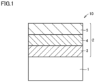
- FIG. 1 A cutting tool according to one embodiment of the present disclosure will be described using Fig. 1 .
- Residual stress X of first layer 3, residual stress Y of second layer 4 and residual stress Z of third layer 5 satisfy the relationship of formula 1: X ⁇ Y ⁇ Z
- This can improve breakage resistance in a relationship where a residual stress on a substrate 1 side of coated film 2 are relatively low.
- film destruction due to stress introduction is lowered in relation to a residual stress on a surface side of coated film 2 being relatively higher, which facilitates inhibition of dropout of a film structure, thereby enabling improvement of wear resistance.
- cutting tool 1 is capable of combining excellent "wear resistance” and excellent “breakage resistance,” whereby a cutting tool with a long tool service life, particularly even in light intermittent turning of alloy steel with a black skin material, can be provided.
- the portion of substrate 1 herein that is involved in cutting refers to, depending on the size and shape of substrate 1, a region surrounded by a cutting edge ridgeline of the cutting tool and a hypothetical plane in which a distance from the cutting edge ridgeline to a substrate 1 side along a perpendicular line tangent to the cutting edge ridgeline, is, for example, either 5 mm, 3 mm, 2 mm, 1 mm, or 0.5 mm.
- Cutting tool 10 of the present embodiment can be suitably used as cutting tools 10 such as a drill, an end mill, an indexable cutting insert for drills, an indexable cutting insert for end mills, an indexable cutting insert for milling, an indexable cutting insert for turning, a metal saw, a gear cutting tool, a reamer, a tap, and the like.
- cutting tools 10 such as a drill, an end mill, an indexable cutting insert for drills, an indexable cutting insert for end mills, an indexable cutting insert for milling, an indexable cutting insert for turning, a metal saw, a gear cutting tool, a reamer, a tap, and the like.
- Substrate 1 that is any conventionally known substrate 1 of this type, can be used.
- it is preferably any of cemented carbides (WC-based cemented carbide, cemented carbide containing WC and Co, cemented carbides further added with carbonitrides of Ti, Ta, Nb, and the like, and the like), cermets (mainly composed of TiC, TiN, TiCN, or the like), high speed steel, ceramics (titanium carbide, silicon carbide, silicon nitride, aluminum nitride, aluminum oxide, and the like), a cubic boron nitride sintered material, or a diamond sintered material.
- cemented carbides WC-based cemented carbide, cemented carbide containing WC and Co, cemented carbides further added with carbonitrides of Ti, Ta, Nb, and the like, and the like
- cermets mainly composed of TiC, TiN, TiCN, or the like
- high speed steel ceramics (titanium carbide, silicon carb
- substrates 1 particularly the WC-based cemented carbide and cermet (particularly TiCN-based cermet), are preferably selected. These substrates 1 are excellent in balance between a hardness and a strength, in particular at high temperatures, whereby in the case of using substrate 1 as that of cutting tool 10, substrate 1 can contribute to a long service life of cutting tool 10.
- Coated film 2 includes first layer 3 positioned on substrate 1, second layer 4 positioned on first layer 3, and third layer 5 positioned on second layer 4. Coated film 2 covering substrate 1 improves various properties such as wear resistance and chipping resistance of cutting tool 10, thereby having an action of prolonging a service life of cutting tool 10. Note, however, coated film 2 can include, in addition to first layer 3, second layer 4, and third layer 5, "other layers" as described below to the extent that the effects of the present disclosure are not impaired.
- a thickness of coated film 2 is preferably 6 ⁇ m or more and 30 ⁇ m or less.
- the thickness of coated film 2 being thinner than 6 ⁇ m facilitates a service life of cutting tool 10 to be shortened due to the too thin thickness of coated film 2.
- the thickness of coated film 2 being thicker than 30 ⁇ m, on the other hand, facilitates chipping of coated film 2 to occur in an early stage of cutting, whereby the service life of cutting tool 10 tends to be likely to shorten.
- a thickness of coated film 3 can be measured by observing a cross-section of coated film 2 with a scanning electron microscope (SEM).
- thickness widths at three locations in one field of view are measured to obtain an average value thereof and used as the "thickness". The same applies to a thickness of each layer described below, unless otherwise described.
- First layer 3 is composed of titanium carbonitride.
- the "being composed of titanium carbonitride” means that unavoidable impurities can be included in addition to titanium carbonitride as long as the effects of the present disclosure are exhibited.
- the unavoidable impurities include, for example, chlorine atoms (Cl) and the like.
- the content rate of the total unavoidable impurities in first layer 3 is preferably greater than 0% by mass and less than 3% by mass.
- First layer 3 being composed of titanium carbonitride is measured by an X-ray diffraction (XRD) method and an energy dispersive X-ray analysis (EDX).
- XRD X-ray diffraction
- EDX energy dispersive X-ray analysis
- the content rate of unavoidable impurities in first layer 3 is measured by secondary ion mass spectrometry (SIMS). Note, however, as long as the measurement is carried out on the same cutting tool 10, it has been confirmed that there is no variation in the measurement results even if measurement points are arbitrarily selected.
- a thickness of first layer 3 is preferably 3 ⁇ m or more and 15 ⁇ m or less. This enables achievement of both superior wear resistance and superior breakage resistance, whereby a cutting tool with a longer tool service life, particularly even in light intermittent turning of alloy steel with a black skin material, can be provided.
- the lower limit of the thickness of first layer 3 is preferably 3 ⁇ m or more, more preferably 5 ⁇ m or more, and further preferably 7 ⁇ m or more.
- the upper limit of the thickness of first layer 3 is preferably 15 ⁇ m or less, more preferably 13 ⁇ m or less, and further preferably 11 ⁇ m or less.
- the thickness of first layer 3 is more preferably 5 ⁇ m or more and 13 ⁇ m or less and further preferably 7 ⁇ m or more and 11 ⁇ m or less.
- a residual stress X of first layer 3 is preferably -1.0 GPa or more and -0.3 GPa or less. This facilitates expansion of damage to be inhibited when minute breakage occurs, whereby a cutting tool with a longer tool service life, particularly even in light intermittent turning of alloy steel with a black skin material, can be provided.
- the lower limit of residual stress X of first layer 3 is preferably -1.0 GPa or more, more preferably -0.9 GPa or more, and further preferably -0.8 GPa or more.
- the upper limit of residual stress X of first layer 3 is preferably -0.3 GPa or less, more preferably - 0.4 GPa or less, and further preferably -0.5 GPa or less. Residual stress X of first layer 3 is more preferably -0.9 GPa or more and -0.4 GPa or less and further preferably -0.8 GPa or more and -0.5 GPa or less.
- Residual stress X of first layer 3 can be identified by carrying out measurement on first layer 3 using a sin2 ⁇ method (see pp. 54 to 66 of " X-ray Stress Measurement Method", the Society of Materials Science, Japan, 1981, published by Yokendo Ltd. Publishers ). It is noted that the temperature is room temperature (20°C) in this measurement. As long as the same cutting tool 10 is used for the measurement, it has also been confirmed that there is no variation in the measurement results even if measurement points are arbitrarily selected.
- Second layer 4 is composed of aluminum oxide.
- the "being composed of aluminum oxide” means that unavoidable impurities can be included in addition to aluminum oxide as long as the effect of the present disclosure is exhibited.
- the unavoidable impurities include, for example, chlorine atoms (Cl) and the like.
- the content rate of the total unavoidable impurities in second layer 4 is greater than 0% by mass and less than 3% by mass.
- Second layer 4 being composed of aluminum oxide is measured by an X-ray diffraction (XRD) method and an energy dispersive X-ray analysis (EDX).
- XRD X-ray diffraction
- EDX energy dispersive X-ray analysis
- the content rate of unavoidable impurities is measured by secondary ion mass spectrometry (SIMS). Note, however, as long as the measurement is carried out on the same cutting tool 10, it has been confirmed that there is no variation in the measurement results even if measurement points are arbitrarily selected.
- a thickness of second layer 4 is preferably 3 ⁇ m or more or 15 ⁇ m or less. This makes it possible to achieve both superior wear resistance and superior breakage resistance, whereby a cutting tool with a longer tool service life, particularly even in light intermittent turning of alloy steel with a black skin material, can be provided.
- the lower limit of the thickness of second layer 4 is preferably 3 ⁇ m or more, more preferably 5 ⁇ m or more, and further preferably 7 ⁇ m or more.
- the upper limit of the thickness of second layer 4 is preferably 15 ⁇ m or less, more preferably 13 ⁇ m or less, and further preferably 11 ⁇ m or less.
- the thickness of second layer 4 is more preferably 5 ⁇ m or more and 13 ⁇ m or less and further preferably 7 ⁇ m or more and 11 ⁇ m or less.
- a residual stress Y of second layer 4 is preferably -0.5 GPa or more and 0.1 GPa or less. This is capable of improving breakage resistance in a relationship where an alumina structure is unlikely to be destroyed due to moderate introduction of a residual stress, whereby a cutting tool with longer tool service life, particularly even in light intermittent turning of alloy steel with a black skin material, can be provided.
- the lower limit of residual stress Y of second layer 4 is preferably -0.5 GPa or more, more preferably -0.4 GPa or more, and further preferably -0.3 GPa or more.
- the upper limit of residual stress Y of second layer 4 is preferably 0.1 GPa or less, more preferably 0 GPa or less, and further preferably -0.1 GPa or less. Residual stress Y of second layer 4 is more preferably -0.4 GPa or more and 0 GPa or less and further preferably -0.3 GPa or more and -0.1 GPa or less.
- Residual stress Y of second layer 4 can be specified by the same method as that for residual stress X of first layer 3, except that measurement is carried out for second layer 4. Note, however, as long as the measurement is carried out on the same cutting tool 10, it has been confirmed that there is no variation in the measurement results even if measurement points are selected arbitrarily.
- Third layer 5 is composed of titanium carbonitride.
- the "being composed of titanium carbonitride” means that unavoidable impurities can be included in addition to titanium carbonitride as long as the effects of the present disclosure are exhibited.
- the unavoidable impurities include, for example, chlorine atoms (Cl) and the like.
- the content rate of the total unavoidable impurities in third layer 5 is preferably greater than 0% by mass and less than 3% by mass.
- Third layer 5 being composed of titanium carbonitride is measured by an X-ray diffraction (XRD) method and an energy dispersive X-ray analysis (EDX).
- XRD X-ray diffraction
- EDX energy dispersive X-ray analysis
- SIMS secondary ion mass spectrometry
- a thickness of third layer 5 is preferably 2 ⁇ m or more and 4 ⁇ m or less. This enables achievement of both superior breakage resistance and superior wear resistance, whereby a cutting tool with a longer tool service life, particularly even in light intermittent turning of alloy steel with a black skin material, can be provided.
- the lower limit of the thickness of third layer 5 is preferably 2 ⁇ m or more and more preferably 2.5 ⁇ m or more.
- the upper limit of the thickness of third layer 5 is preferably 4 ⁇ m or less and more preferably 3.5 ⁇ m or less.
- the thickness of third layer 5 is more preferably 2.5 ⁇ m or more and 3.5 ⁇ m or less.
- a residual stress Z of third layer 5 is preferably -0.3 GPa or more and 0.4 GPa or less. This facilitates inhibition of flank face wear in an early stage of processing, whereby a cutting tool with a longer tool service life, particularly even in light intermittent turning of alloy steel with a black skin material, can be provided.
- the lower limit of residual stress Z of third layer 5 is preferably -0.3 GPa or more, more preferably -0.2 GPa or more, and further preferably -0.1 GPa or more.
- the upper limit of residual stress Z of third layer 5 is preferably 0.4 GPa or less, more preferably 0.3 GPa or less, and further preferably 0.2 GPa or less. Residual stress Z of third layer 5 is more preferably -0.2 GPa or more and 0.3 GPa or less and further preferably -0.1 GPa or more and 0.2 GPa or less.
- Residual stress Z of third layer 5 can be identified by the same measurement method as that for residual stress X of first layer 3, except that the measurement is carried out on third layer 5. As long as the measurement is carried out on the same cutting tool 10, it has been confirmed that there is no variation in the measurement results even if the measurement points are arbitrarily selected.
- Residual stress X of first layer 3, residual stress Y of second layer 4 and residual stress Z of third layer 5 satisfy the relationship of formula 1: X ⁇ Y ⁇ Z
- a Y-X is preferably 0.1 or more and 0.6 or less. This hardly causes chipping to occur from first layer 3 toward second layer 4, whereby cutting tool can have superior breakage resistance.
- Y-X is more preferably 0.15 or more and 0.55 or less and further preferably 0.2 or more and 0.5 or less.
- a Y-Z is preferably -0.6 or more and -0.1 or less. This hardly causes chipping to occur from second layer 4 toward third layer 5, whereby cutting tool 10 can have superior breakage resistance.
- Y-Z is more preferably -0.55 or more and -0.15 or less and further preferably -0.50 or more and -0.20 or less.
- Examples of other layers can include, for example, a base layer (not shown), an intermediate layer (not shown), a surface layer (not shown), and the like.
- the base layer is a layer arranged between substrate 1 and first layer 3.
- the surface layer is a layer positioned on a surface of coated film 2.
- the intermediate layer is a layer arranged between first layer 3 and second layer 4, between second layer 4 and third layer 5, or layers arranged both therebetween. Note, however, the intermediate layer is a thin adhesion layer such as TiCNO. Therefore, the intermediate layer has no effect on a stress distribution.
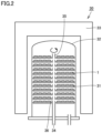
- FIG. 2 is a schematic cross-sectional view of an example of a CVD apparatus used in the manufacturing of the cutting tool of the present embodiment.
- the method for manufacturing the cutting tool of the present embodiment is a method for manufacturing the cutting tool described in Embodiment 1, including
- a substrate is prepared.
- the substrate can be the substrate described in Embodiment 1.
- a cemented carbide when used as the substrate, a commercially available substrate may be used, or the substrate may be manufactured by a general powder metallurgical method.
- the manufacturing by the general powder metallurgical method for example, WC powder, Co powder, and the like, are mixed by a ball mill or the like to obtain mixed powder. After drying the mixed powder, it is formed into a predetermined shape to obtain a formed material. The formed material is then sintered to obtain a WC-Co cemented carbide (sintered material). Next, the sintered material is subjected to predetermined cutting edge processing, such as honing, to be able to manufacture a substrate composed of a WC-Co cemented carbide.
- predetermined cutting edge processing such as honing
- a coated film is formed on the substrate described above to obtain a cutting tool.
- the formation of the coated film is performed, for example, by using the CVD apparatus shown in Fig. 2 .
- a CVD apparatus 30 is equipped with a plurality of substrate-setting jigs 31 for holding substrate 1 and a reaction vessel 32 made of heat-resistant alloy steel covering substrate-setting jigs 31.
- a temperature regulator 33 is arranged for controlling temperature inside reaction vessel 32.
- Reaction vessel 32 is provided with a gas inlet pipe 35 having a gas inlet port 34.
- Gas inlet pipe 35 is arranged so as to extend toward a vertical direction and be rotatable about an axis in the vertical direction, in an inner space of reaction vessel 32 where substrate-setting jigs 31 is arranged, and is provided with a plurality of blowout holes (through holes 36) for allowing gas to blow out into reaction vessel 32.
- the first layer, second layer, and third layer, which constitute the aforementioned coated film can be formed as follows.
- the second step includes the second A step of forming the first layer by the CVD method, the second B step of forming the second layer by the CVD method, and the second C step of forming the third layer by the CVD method, in this order.
- the coated film includes the "other layers” described in Embodiment 1, the "other layers" can be formed by conventionally known methods.
- the first layer is formed by the CVD method. More specifically, first, substrate 1 is arranged on substrate-setting jig 31, and while controlling temperature and pressure in reaction vessel 32 to a predetermined range, a raw material gas for the first layer is introduced into reaction vessel 32 from gas inlet pipe 35. This allows the first layer to be formed on substrate 1.
- the content rate of TiCl 4 in the mixed gas is preferably 8.0% by volume or more and 9.0% by volume or less.
- the content rate of CH 3 CN in the mixed gas is preferably 0.2% by volume or more and 1.0% by volume or less.
- the content rate of CO in the mixed gas is preferably 1.3% by volume or more and 2.0% by volume or less.
- the content rate of N 2 in the mixed gas is preferably 8.0% by volume or more and 12.0% by volume or less.
- the content rate of HCl in the mixed gas is preferably 1.0% by volume or more and 3.0% by volume or less.
- a temperature in reaction vessel 32 is preferably controlled at 800°C or more and 850°C or less, and pressure in reaction vessel 32 is preferably controlled at 100 hPa or more and 120 hPa or less. Note, however, gas inlet pipe 35 is preferably rotated upon introduction of gas.
- control of each condition of the CVD method changes an aspect of the first layer. For example, by adjusting a deposition time, a thickness of the first layer is controlled.
- the second layer is formed by the CVD method. More specifically, first, the first cutting tool precursor in which the first layer has been formed on a substrate is arranged on substrate-setting jig 31, and while controlling temperature and pressure in reaction vessel 32 to a predetermined range, a raw material gas for the second layer is introduced into reaction vessel 32 from gas inlet pipe 35. This allows the second layer to be formed on the first layer.
- a mix gas of AlCl 3 , CO 2 , H 2 S, and H 2 is used as the raw material gas for the second layer.
- the content rate of AlCl 3 in the mixed gas is preferably 2.0% by volume or more and 2.5% by volume or less.
- the content rate of CO 2 in the mixed gas is preferably 2.5% by volume or more and 3.5% by volume or less.
- the content rate of H 2 S in the mixed gas is preferably 0.5% by volume or more and 1.0% by volume or less.
- a temperature in reaction vessel 32 is preferably controlled at 980°C or more and 1015°C or less, and pressure in reaction vessel 32 is preferably controlled at 60 hPa or more and 75 hPa or less. It is noted that gas inlet pipe 35 is preferably rotated upon introduction of gas.
- control of each condition of the CVD method changes an aspect of the second layer. For example, by adjusting a deposition time, a thickness of the second layer is controlled.
- the third layer is formed by the CVD method. More specifically, first, the second cutting tool precursor in which the first layer is formed on a substrate and the second layer was formed on the first layer is arranged on substrate-setting jig 31, and while controlling temperature and pressure in reaction vessel 32 to a predetermined range, a raw material gas for the third layer is introduced into reaction vessel 32 from gas inlet pipe 35. This allows the third layer to be formed on the second layer.
- a mix gas of TiCl 4 , CH 3 CN, CO, N 2 , HCl, and H 2 is used.
- the content rate of TiCl 4 in the mixed gas is preferably 8.0% by volume or more and 9.0% by volume or less.
- the content rate of CH 3 CN in the mixed gas is preferably 0.2% by volume or more and 0.8% by volume or less.
- the content rate of CO in the mixed gas is preferably 1.3% by volume or more and 2.0% by volume or less.
- the content rate of N 2 in the mixed gas is preferably 8.0% by volume or more and 12.0% by volume or less.
- the content rate of HCl in the mixed gas is preferably 1.0% by volume or more and 3.0% by volume or less.
- a temperature in reaction vessel 32 is preferably controlled at 950°C or more and 1000°C or less, and pressure in reaction vessel 32 is preferably controlled at 80 hPa or more and 100 hPa or less. Note, however, gas inlet pipe 35 is preferably rotated upon introduction of gas.
- control of each condition of the CVD method changes an aspect of the third layer. For example, by adjusting a deposition time, a thickness of the third layer is controlled.
- ⁇ Third step Step of subjecting a coated film to blast processing to obtain a cutting tool>
- a coated film is subjected to blast processing to obtain a cutting tool.
- blast processing refers to processing in which a large number of small spheres (media) of steel, a nonferrous metal (for example, a ceramic), or the like is collided (projected) onto a surface of a coated film, such as a rake face at high speed, to change various properties of the surface, such as a residual stress.
- Examples of the type of medium include a ceramic, zirconia, alumina, and the like.
- a concentration of the media to be projected is 100 g/min or more and 350 g/min or less.
- the concentration of the media to be projected is preferably 150 g/min or more and 250 g/min or less.
- a distance between a projection area where the media are projected and a surface of a coated film (also referred to as "projection distance") is 35 mm or more and 60 mm or less.
- the projection distance is preferably 35 mm or more and 50 mm or less.
- a projection angle of the media is 75° to a surface of a coated film.
- Pressure applied to the aforementioned media upon projection is preferably 0.10 MPa or more and 0.50 MPa or less and more preferably 0.15 MPa or more and 0.45 MPa or less.
- a processing time of blast processing is preferably 20 seconds or more and 30 seconds or less.
- Each condition of the aforementioned blast processing can be appropriately adjusted according to a composition of the aforementioned coated film.
- an additional step may be appropriately carried out in addition to the steps described above, to the extent that the effects of the present embodiment are not impaired.
- the first layer was formed on the above substrate by the CVD method under the following conditions so that the composition of the first layer was as described in Tables 3 and 4 (the second A step).
- a deposition time was appropriately adjusted so that a thickness of the first layer was as described in Tables 3 and 4.
- the second layer was formed on the above first layer by the CVD method under the following conditions so that a composition of the second layer was as described in Tables 3 and 4 (the second B step).
- a deposition time was appropriately adjusted so that a thickness of the second layer was as described in Tables 3 and 4.
- the third layer was formed on the above second layer by the CVD method under the following conditions so that a composition of the third layer was as described in Tables 3 and 4 (the second C step).
- a deposition time was appropriately adjusted so that a thickness of the third layer was as described in Tables 3 and 4.
- Blast processing was performed on a surface of the cutting tool with the first layer, second layer, and third layer formed (in other words, a cutting tool with a coated film formed) under the conditions described in Tables 1 and 2.
- the cutting tools according to samples 1 to 31 correspond to Examples.
- the cutting tools according to samples 101 to 104 correspond to Comparative Examples. From the results of Tables 3 and 4, compared to the cutting tools according to samples 101 to 104, the cutting tools according to samples 1 to 31 were found to have a longer tool service life, even in light intermittent turning of alloy steel with a black skin material.
- the cutting tools according to samples 1 to 31 have a long tool service life, particularly even in light intermittent turning of alloy steel with a black skin material.
Landscapes
- Chemical & Material Sciences (AREA)
- Engineering & Computer Science (AREA)
- Mechanical Engineering (AREA)
- Chemical Kinetics & Catalysis (AREA)
- Materials Engineering (AREA)
- Metallurgy (AREA)
- Organic Chemistry (AREA)
- Inorganic Chemistry (AREA)
- General Chemical & Material Sciences (AREA)
- Ceramic Engineering (AREA)
- Cutting Tools, Boring Holders, And Turrets (AREA)
- Chemical Vapour Deposition (AREA)
Abstract
Description
- The present disclosure relates to a cutting tool.
- Conventionally, cutting tools including a substrate and a coated film arranged on the substrate, have been used for cutting processing (
Patent Literatures 1 to 6). -
- PTL 1:
Japanese Patent Laying-Open No. 2020-037150 - PTL 2:
Japanese Patent Laying-Open No. 2020-116645 - PTL 3:
WO2009/112116 - PTL 4:
WO2022/244241 - PTL 5:
WO2022/244242 - PTL 6:
WO2022/244243 - The cutting tool of the present disclosure is a cutting tool including a substrate and a coated film arranged on the substrate,
- wherein the coated film includes a first layer positioned on the substrate, a second layer positioned on the first layer, and a third layer positioned on the second layer,
- wherein the first layer is composed of titanium carbonitride,
- wherein the second layer is composed of aluminum oxide,
- wherein the third layer is composed of titanium carbonitride,
- wherein a residual stress X of the first layer, a residual stress Y of the second layer and a residual stress Z of the third layer satisfy a relationship of formula 1:

-
-
Fig. 1 is a schematic cross-sectional view illustrating one aspect of the cutting tool of the present disclosure. -
Fig. 2 is a schematic cross-sectional view of an example of a CVD (Chemical Vapor Deposition) apparatus used in manufacturing of the cutting tool of the present disclosure. - In recent years, there have been increasing demands for improvement on a tool service life, particularly in light intermittent turning of alloy steel with a black skin material. Examples of important factors for further improvement on the tool service life in light intermittent turning of alloy steel with a black skin material include "wear resistance" and "breakage resistance". Moreover, from the viewpoint of improving wear resistance, in light intermittent turning of alloy steel with a black skin material, a cutting tool including a substrate and a coated film arranged on the substrate, wherein the coated film includes a first layer positioned on the substrate, a second layer positioned on the first layer, and a third layer positioned on the second layer, the first layer is composed of titanium carbonitride, the second layer is composed of aluminum oxide, and the third layer is composed of titanium carbonitride, is used. However, such a coated film may have had insufficient "breakage resistance" due to difficulty in introducing a sufficient residual stress to the first layer in relation to the third layer being likely to be destroyed by blast processing. Moreover, wear may have easily resulted due to minute damage caused by insufficient "breakage resistance" (i.e., "wear resistance" may have been insufficient). Therefore, by combining excellent "wear resistance" with excellent "breakage resistance", prolongation of a tool service life has been required, particularly even in light intermittent turning of alloy steel with a black skin material.
- Therefore, an object of the present disclosure is to provide a cutting tool having a long tool service life, particularly even in light intermittent turning of alloy steel with a black skin material.
- According to the present disclosure, a cutting tool having a long tool service life, particularly even in light intermittent turning of alloy steel with a black skin material, can be provided.
- Embodiments of the present disclosure will be first described by listing them.
- (1) The cutting tool of the present disclosure is
- a cutting tool including a substrate and a coated film arranged on the substrate,
- wherein the coated film includes a first layer positioned on the substrate, a second layer positioned on the first layer, and a third layer positioned on the second layer,
- wherein the first layer is composed of titanium carbonitride,
- wherein the second layer is composed of aluminum oxide,
- wherein the third layer is composed of titanium carbonitride,
- wherein a residual stress X of the first layer, a residual stress Y of the second layer and a residual stress Z of the third layer satisfy a relationship of formula 1:

- (2) In (1) above, the residual stress X of the first layer is preferably -1.0 GPa or more and -0.3 GPa or less. This can provide a cutting tool having a longer tool service life, particularly even in light intermittent turning of alloy steel with a black skin material.
- (3) In (1) or (2) above, the residual stress Y of the second layer is preferably - 0.5 GPa or more and 0.1 GPa or less. This can provide a cutting tool having a longer tool service life, particularly even in light intermittent turning of alloy steel with a black skin material.
- (4) In any one of (1) to (3) above, the residual stress Z of the third layer is preferably -0.3 GPa or more and 0.4 GPa or less. This can provide a cutting tool with a longer tool service life, particularly even in light intermittent turning of alloy steel with a black skin material.
- (5) In any one of (1) to (4) above, a thickness of the first layer is preferably 3 µm or more and 15 µm or less. This can provide a cutting tool with a longer tool service life, particularly even in light intermittent turning of alloy steel with a black skin material.
- (6) In any one of from (1) to (5), a thickness of the second layer is preferably 3 µm or more and 15 µm or less. This can provide a cutting tool with a longer tool service life, particularly even in light intermittent turning of alloy steel with a black skin material.
- (7) In any one of (1) to (6), a thickness of the third layer is preferably 2 µm or more and 4 µm or less. This can provide a cutting tool with a longer tool service life, particularly even in light intermittent turning of alloy steel with a black skin material.
- Specific examples of one embodiment of the present disclosure (hereinafter also referred to as "the present embodiment") will be described below with referring to the drawings. In the drawings of the present disclosure, the same reference sign represents the same portion or equivalent portion. Moreover, dimensional relationships such as a length, width, thickness, and depth have been appropriately changed for the sake of clarity and simplification of the drawings, and do not necessarily represent actual dimensional relationships.
- The notation in the form "A to B" used herein refers to the upper limit and lower limit of the range (i.e., A or more and B or less), and when no unit is described in A and a unit is described only in B, the unit of A is the same as that of B.
- A cutting tool according to one embodiment of the present disclosure will be described using
Fig. 1 . - One embodiment of the present disclosure (hereinafter also referred to as the "present embodiment") is
- a
cutting tool 10 including asubstrate 1 and a coatedfilm 2 arranged onsubstrate 1, - wherein coated
film 2 includes afirst layer 3 positioned onsubstrate 1, asecond layer 4 positioned onfirst layer 3, and athird layer 5 positioned onsecond layer 4, - wherein
first layer 3 is composed of titanium carbonitride, - wherein
second layer 4 is composed of aluminum oxide, - wherein
third layer 5 is composed of titanium carbonitride, - wherein a residual stress X of
first layer 3, a residual stress Y ofsecond layer 4 and a residual stress Z ofthird layer 5 satisfy a relationship of formula 1:
- According to the present disclosure, it is possible to provide a cutting tool with a long tool service life, particularly even in light intermittent turning of alloy steel with a black skin material. The reason therefore is presumed as follows.
- Residual stress X of
first layer 3, residual stress Y ofsecond layer 4 and residual stress Z ofthird layer 5 satisfy the relationship of formula 1:
substrate 1 side ofcoated film 2 are relatively low. Moreover, film destruction due to stress introduction is lowered in relation to a residual stress on a surface side ofcoated film 2 being relatively higher, which facilitates inhibition of dropout of a film structure, thereby enabling improvement of wear resistance. - In other words, according to the present disclosure, cutting
tool 1 is capable of combining excellent "wear resistance" and excellent "breakage resistance," whereby a cutting tool with a long tool service life, particularly even in light intermittent turning of alloy steel with a black skin material, can be provided. - As shown in
Fig. 1 , cuttingtool 10 according to one embodiment of the present disclosure includessubstrate 1 andcoated film 2 arranged onsubstrate 1.Coated film 2 preferably covers the entire surface ofsubstrate 1, however, even if a portion ofsubstrate 1 is not covered bycoated film 2 or a composition ofcoated film 2 is partially different, the scope of the present embodiment shall not be deviated. In a case in which a portion ofsubstrate 1 is not covered withcoated film 2,coated film 2 is preferably arranged so as to cover a surface of a portion ofsubstrate 1 at least involved in cutting. The portion ofsubstrate 1 herein that is involved in cutting refers to, depending on the size and shape ofsubstrate 1, a region surrounded by a cutting edge ridgeline of the cutting tool and a hypothetical plane in which a distance from the cutting edge ridgeline to asubstrate 1 side along a perpendicular line tangent to the cutting edge ridgeline, is, for example, either 5 mm, 3 mm, 2 mm, 1 mm, or 0.5 mm. - Cutting
tool 10 of the present embodiment can be suitably used as cuttingtools 10 such as a drill, an end mill, an indexable cutting insert for drills, an indexable cutting insert for end mills, an indexable cutting insert for milling, an indexable cutting insert for turning, a metal saw, a gear cutting tool, a reamer, a tap, and the like. -
Substrate 1 that is any conventionally knownsubstrate 1 of this type, can be used. For example, it is preferably any of cemented carbides (WC-based cemented carbide, cemented carbide containing WC and Co, cemented carbides further added with carbonitrides of Ti, Ta, Nb, and the like, and the like), cermets (mainly composed of TiC, TiN, TiCN, or the like), high speed steel, ceramics (titanium carbide, silicon carbide, silicon nitride, aluminum nitride, aluminum oxide, and the like), a cubic boron nitride sintered material, or a diamond sintered material. - Among these
various substrates 1, particularly the WC-based cemented carbide and cermet (particularly TiCN-based cermet), are preferably selected. Thesesubstrates 1 are excellent in balance between a hardness and a strength, in particular at high temperatures, whereby in the case of usingsubstrate 1 as that of cuttingtool 10,substrate 1 can contribute to a long service life of cuttingtool 10. -
Coated film 2 includesfirst layer 3 positioned onsubstrate 1,second layer 4 positioned onfirst layer 3, andthird layer 5 positioned onsecond layer 4.Coated film 2covering substrate 1 improves various properties such as wear resistance and chipping resistance of cuttingtool 10, thereby having an action of prolonging a service life of cuttingtool 10. Note, however,coated film 2 can include, in addition tofirst layer 3,second layer 4, andthird layer 5, "other layers" as described below to the extent that the effects of the present disclosure are not impaired. - A thickness of
coated film 2 is preferably 6 µm or more and 30 µm or less. The thickness ofcoated film 2 being thinner than 6 µm facilitates a service life of cuttingtool 10 to be shortened due to the too thin thickness ofcoated film 2. The thickness ofcoated film 2 being thicker than 30 µm, on the other hand, facilitates chipping ofcoated film 2 to occur in an early stage of cutting, whereby the service life of cuttingtool 10 tends to be likely to shorten. A thickness ofcoated film 3 can be measured by observing a cross-section ofcoated film 2 with a scanning electron microscope (SEM). Specifically, with observation magnification of a cross-sectional sample of 5,000 to 10,000 times and an observation area of 100 to 500 µm2, thickness widths at three locations in one field of view, are measured to obtain an average value thereof and used as the "thickness". The same applies to a thickness of each layer described below, unless otherwise described. -
First layer 3 is composed of titanium carbonitride. Here, the "being composed of titanium carbonitride" means that unavoidable impurities can be included in addition to titanium carbonitride as long as the effects of the present disclosure are exhibited. Examples of the unavoidable impurities include, for example, chlorine atoms (Cl) and the like. The content rate of the total unavoidable impurities infirst layer 3 is preferably greater than 0% by mass and less than 3% by mass. -
First layer 3 being composed of titanium carbonitride is measured by an X-ray diffraction (XRD) method and an energy dispersive X-ray analysis (EDX). The content rate of unavoidable impurities infirst layer 3 is measured by secondary ion mass spectrometry (SIMS). Note, however, as long as the measurement is carried out on thesame cutting tool 10, it has been confirmed that there is no variation in the measurement results even if measurement points are arbitrarily selected. - A thickness of
first layer 3 is preferably 3 µm or more and 15 µm or less. This enables achievement of both superior wear resistance and superior breakage resistance, whereby a cutting tool with a longer tool service life, particularly even in light intermittent turning of alloy steel with a black skin material, can be provided. The lower limit of the thickness offirst layer 3 is preferably 3 µm or more, more preferably 5 µm or more, and further preferably 7 µm or more. The upper limit of the thickness offirst layer 3 is preferably 15 µm or less, more preferably 13 µm or less, and further preferably 11 µm or less. The thickness offirst layer 3 is more preferably 5 µm or more and 13 µm or less and further preferably 7 µm or more and 11 µm or less. - A residual stress X of
first layer 3 is preferably -1.0 GPa or more and -0.3 GPa or less. This facilitates expansion of damage to be inhibited when minute breakage occurs, whereby a cutting tool with a longer tool service life, particularly even in light intermittent turning of alloy steel with a black skin material, can be provided. The lower limit of residual stress X offirst layer 3 is preferably -1.0 GPa or more, more preferably -0.9 GPa or more, and further preferably -0.8 GPa or more. The upper limit of residual stress X offirst layer 3 is preferably -0.3 GPa or less, more preferably - 0.4 GPa or less, and further preferably -0.5 GPa or less. Residual stress X offirst layer 3 is more preferably -0.9 GPa or more and -0.4 GPa or less and further preferably -0.8 GPa or more and -0.5 GPa or less. - Residual stress X of
first layer 3 can be identified by carrying out measurement onfirst layer 3 using a sin2ψ method (see pp. 54 to 66 of "X-ray Stress Measurement Method", the Society of Materials Science, Japan, 1981, published by Yokendo Ltd. Publishers). It is noted that the temperature is room temperature (20°C) in this measurement. As long as thesame cutting tool 10 is used for the measurement, it has also been confirmed that there is no variation in the measurement results even if measurement points are arbitrarily selected. -
Second layer 4 is composed of aluminum oxide. Here, the "being composed of aluminum oxide" means that unavoidable impurities can be included in addition to aluminum oxide as long as the effect of the present disclosure is exhibited. Examples of the unavoidable impurities include, for example, chlorine atoms (Cl) and the like. The content rate of the total unavoidable impurities insecond layer 4 is greater than 0% by mass and less than 3% by mass. -
Second layer 4 being composed of aluminum oxide is measured by an X-ray diffraction (XRD) method and an energy dispersive X-ray analysis (EDX). Insecond layer 4, the content rate of unavoidable impurities is measured by secondary ion mass spectrometry (SIMS). Note, however, as long as the measurement is carried out on thesame cutting tool 10, it has been confirmed that there is no variation in the measurement results even if measurement points are arbitrarily selected. - A thickness of
second layer 4 is preferably 3 µm or more or 15 µm or less. This makes it possible to achieve both superior wear resistance and superior breakage resistance, whereby a cutting tool with a longer tool service life, particularly even in light intermittent turning of alloy steel with a black skin material, can be provided. The lower limit of the thickness ofsecond layer 4 is preferably 3 µm or more, more preferably 5 µm or more, and further preferably 7 µm or more. The upper limit of the thickness ofsecond layer 4 is preferably 15 µm or less, more preferably 13 µm or less, and further preferably 11 µm or less. The thickness ofsecond layer 4 is more preferably 5 µm or more and 13 µm or less and further preferably 7 µm or more and 11 µm or less. - A residual stress Y of
second layer 4 is preferably -0.5 GPa or more and 0.1 GPa or less. This is capable of improving breakage resistance in a relationship where an alumina structure is unlikely to be destroyed due to moderate introduction of a residual stress, whereby a cutting tool with longer tool service life, particularly even in light intermittent turning of alloy steel with a black skin material, can be provided. The lower limit of residual stress Y ofsecond layer 4 is preferably -0.5 GPa or more, more preferably -0.4 GPa or more, and further preferably -0.3 GPa or more. The upper limit of residual stress Y ofsecond layer 4 is preferably 0.1 GPa or less, more preferably 0 GPa or less, and further preferably -0.1 GPa or less. Residual stress Y ofsecond layer 4 is more preferably -0.4 GPa or more and 0 GPa or less and further preferably -0.3 GPa or more and -0.1 GPa or less. - Residual stress Y of
second layer 4 can be specified by the same method as that for residual stress X offirst layer 3, except that measurement is carried out forsecond layer 4. Note, however, as long as the measurement is carried out on thesame cutting tool 10, it has been confirmed that there is no variation in the measurement results even if measurement points are selected arbitrarily. -
Third layer 5 is composed of titanium carbonitride. Here, the "being composed of titanium carbonitride" means that unavoidable impurities can be included in addition to titanium carbonitride as long as the effects of the present disclosure are exhibited. The unavoidable impurities include, for example, chlorine atoms (Cl) and the like. The content rate of the total unavoidable impurities inthird layer 5 is preferably greater than 0% by mass and less than 3% by mass. -
Third layer 5 being composed of titanium carbonitride is measured by an X-ray diffraction (XRD) method and an energy dispersive X-ray analysis (EDX). Inthird layer 5, the content rate of unavoidable impurities is measured by secondary ion mass spectrometry (SIMS). As long as the measurement is carried out on thesame cutting tool 10, it has been confirmed that there is no variation in the measurement results even if measurement points are arbitrarily selected. - A thickness of
third layer 5 is preferably 2 µm or more and 4 µm or less. This enables achievement of both superior breakage resistance and superior wear resistance, whereby a cutting tool with a longer tool service life, particularly even in light intermittent turning of alloy steel with a black skin material, can be provided. The lower limit of the thickness ofthird layer 5 is preferably 2 µm or more and more preferably 2.5 µm or more. The upper limit of the thickness ofthird layer 5 is preferably 4 µm or less and more preferably 3.5 µm or less. The thickness ofthird layer 5 is more preferably 2.5 µm or more and 3.5 µm or less. - A residual stress Z of
third layer 5 is preferably -0.3 GPa or more and 0.4 GPa or less. This facilitates inhibition of flank face wear in an early stage of processing, whereby a cutting tool with a longer tool service life, particularly even in light intermittent turning of alloy steel with a black skin material, can be provided. The lower limit of residual stress Z ofthird layer 5 is preferably -0.3 GPa or more, more preferably -0.2 GPa or more, and further preferably -0.1 GPa or more. The upper limit of residual stress Z ofthird layer 5 is preferably 0.4 GPa or less, more preferably 0.3 GPa or less, and further preferably 0.2 GPa or less. Residual stress Z ofthird layer 5 is more preferably -0.2 GPa or more and 0.3 GPa or less and further preferably -0.1 GPa or more and 0.2 GPa or less. - Residual stress Z of
third layer 5 can be identified by the same measurement method as that for residual stress X offirst layer 3, except that the measurement is carried out onthird layer 5. As long as the measurement is carried out on thesame cutting tool 10, it has been confirmed that there is no variation in the measurement results even if the measurement points are arbitrarily selected. - Residual stress X of
first layer 3, residual stress Y ofsecond layer 4 and residual stress Z ofthird layer 5 satisfy the relationship of formula 1:
tool 10 to combine both the excellent wear resistance and excellent breakage resistance, whereby cuttingtool 10 can exhibit a long tool service life, particularly even in light intermittent turning of alloy steel with a black skin material. - A Y-X is preferably 0.1 or more and 0.6 or less. This hardly causes chipping to occur from
first layer 3 towardsecond layer 4, whereby cutting tool can have superior breakage resistance. Y-X is more preferably 0.15 or more and 0.55 or less and further preferably 0.2 or more and 0.5 or less. - A Y-Z is preferably -0.6 or more and -0.1 or less. This hardly causes chipping to occur from
second layer 4 towardthird layer 5, whereby cuttingtool 10 can have superior breakage resistance. Y-Z is more preferably -0.55 or more and -0.15 or less and further preferably -0.50 or more and -0.20 or less. - Examples of other layers can include, for example, a base layer (not shown), an intermediate layer (not shown), a surface layer (not shown), and the like. The base layer is a layer arranged between
substrate 1 andfirst layer 3. The surface layer is a layer positioned on a surface ofcoated film 2. The intermediate layer is a layer arranged betweenfirst layer 3 andsecond layer 4, betweensecond layer 4 andthird layer 5, or layers arranged both therebetween. Note, however, the intermediate layer is a thin adhesion layer such as TiCNO. Therefore, the intermediate layer has no effect on a stress distribution. - A method for manufacturing the cutting tool of the present embodiment will be described using
Fig. 2. Fig. 2 is a schematic cross-sectional view of an example of a CVD apparatus used in the manufacturing of the cutting tool of the present embodiment. - The method for manufacturing the cutting tool of the present embodiment is a method for manufacturing the cutting tool described in
Embodiment 1, including - the first step of preparing a substrate,
- the second step of forming a coated film on the substrate, and
- the third step of subjecting the coated film to blast processing, to obtain a cutting tool,
- wherein the second step includes the second A step of forming the first layer by a CVD method, the second B step of forming the second layer by the CVD method, and the second C step of forming the third layer by the CVD method, in this order. The details of each process will be described below.
- In the first step, a substrate is prepared. The substrate can be the substrate described in
Embodiment 1. - For example, when a cemented carbide is used as the substrate, a commercially available substrate may be used, or the substrate may be manufactured by a general powder metallurgical method. In the case of the manufacturing by the general powder metallurgical method, for example, WC powder, Co powder, and the like, are mixed by a ball mill or the like to obtain mixed powder. After drying the mixed powder, it is formed into a predetermined shape to obtain a formed material. The formed material is then sintered to obtain a WC-Co cemented carbide (sintered material). Next, the sintered material is subjected to predetermined cutting edge processing, such as honing, to be able to manufacture a substrate composed of a WC-Co cemented carbide. A substrate other than those described above can also be prepared, as long as it is conventionally known as a substrate of this type.
- In the second step, a coated film is formed on the substrate described above to obtain a cutting tool. The formation of the coated film is performed, for example, by using the CVD apparatus shown in
Fig. 2 . ACVD apparatus 30 is equipped with a plurality of substrate-settingjigs 31 for holdingsubstrate 1 and areaction vessel 32 made of heat-resistant alloy steel covering substrate-settingjigs 31. Moreover, at a circumference ofreaction vessel 32, atemperature regulator 33 is arranged for controlling temperature insidereaction vessel 32.Reaction vessel 32 is provided with agas inlet pipe 35 having agas inlet port 34.Gas inlet pipe 35 is arranged so as to extend toward a vertical direction and be rotatable about an axis in the vertical direction, in an inner space ofreaction vessel 32 where substrate-settingjigs 31 is arranged, and is provided with a plurality of blowout holes (through holes 36) for allowing gas to blow out intoreaction vessel 32. By using thisCVD apparatus 30, the first layer, second layer, and third layer, which constitute the aforementioned coated film, can be formed as follows. - The second step includes the second A step of forming the first layer by the CVD method, the second B step of forming the second layer by the CVD method, and the second C step of forming the third layer by the CVD method, in this order. In a case in which the coated film includes the "other layers" described in
Embodiment 1, the "other layers" can be formed by conventionally known methods. - In the second A step, the first layer is formed by the CVD method. More specifically, first,
substrate 1 is arranged on substrate-settingjig 31, and while controlling temperature and pressure inreaction vessel 32 to a predetermined range, a raw material gas for the first layer is introduced intoreaction vessel 32 fromgas inlet pipe 35. This allows the first layer to be formed onsubstrate 1. - As the raw material gas for the first layer, a mix gas of TiCl4, CH3CN, CO, N2, HCl, and H2 is used.
- The content rate of TiCl4 in the mixed gas is preferably 8.0% by volume or more and 9.0% by volume or less. The content rate of CH3CN in the mixed gas is preferably 0.2% by volume or more and 1.0% by volume or less. The content rate of CO in the mixed gas is preferably 1.3% by volume or more and 2.0% by volume or less. The content rate of N2 in the mixed gas is preferably 8.0% by volume or more and 12.0% by volume or less. The content rate of HCl in the mixed gas is preferably 1.0% by volume or more and 3.0% by volume or less.
- A temperature in
reaction vessel 32 is preferably controlled at 800°C or more and 850°C or less, and pressure inreaction vessel 32 is preferably controlled at 100 hPa or more and 120 hPa or less. Note, however,gas inlet pipe 35 is preferably rotated upon introduction of gas. - With respect to the aforementioned manufacturing method, control of each condition of the CVD method changes an aspect of the first layer. For example, by adjusting a deposition time, a thickness of the first layer is controlled.
- In the second B step, the second layer is formed by the CVD method. More specifically, first, the first cutting tool precursor in which the first layer has been formed on a substrate is arranged on substrate-setting
jig 31, and while controlling temperature and pressure inreaction vessel 32 to a predetermined range, a raw material gas for the second layer is introduced intoreaction vessel 32 fromgas inlet pipe 35. This allows the second layer to be formed on the first layer. - As the raw material gas for the second layer, a mix gas of AlCl3, CO2, H2S, and H2 is used.
- The content rate of AlCl3 in the mixed gas is preferably 2.0% by volume or more and 2.5% by volume or less. The content rate of CO2 in the mixed gas is preferably 2.5% by volume or more and 3.5% by volume or less. The content rate of H2S in the mixed gas is preferably 0.5% by volume or more and 1.0% by volume or less.
- A temperature in
reaction vessel 32 is preferably controlled at 980°C or more and 1015°C or less, and pressure inreaction vessel 32 is preferably controlled at 60 hPa or more and 75 hPa or less. It is noted thatgas inlet pipe 35 is preferably rotated upon introduction of gas. - With respect to the aforementioned manufacturing method, control of each condition of the CVD method changes an aspect of the second layer. For example, by adjusting a deposition time, a thickness of the second layer is controlled.
- In the second C step, the third layer is formed by the CVD method. More specifically, first, the second cutting tool precursor in which the first layer is formed on a substrate and the second layer was formed on the first layer is arranged on substrate-setting
jig 31, and while controlling temperature and pressure inreaction vessel 32 to a predetermined range, a raw material gas for the third layer is introduced intoreaction vessel 32 fromgas inlet pipe 35. This allows the third layer to be formed on the second layer. - As the raw material gas for the third layer, a mix gas of TiCl4, CH3CN, CO, N2, HCl, and H2 is used.
- The content rate of TiCl4 in the mixed gas is preferably 8.0% by volume or more and 9.0% by volume or less. The content rate of CH3CN in the mixed gas is preferably 0.2% by volume or more and 0.8% by volume or less. The content rate of CO in the mixed gas is preferably 1.3% by volume or more and 2.0% by volume or less. The content rate of N2 in the mixed gas is preferably 8.0% by volume or more and 12.0% by volume or less. The content rate of HCl in the mixed gas is preferably 1.0% by volume or more and 3.0% by volume or less.
- A temperature in
reaction vessel 32 is preferably controlled at 950°C or more and 1000°C or less, and pressure inreaction vessel 32 is preferably controlled at 80 hPa or more and 100 hPa or less. Note, however,gas inlet pipe 35 is preferably rotated upon introduction of gas. - With respect to the aforementioned manufacturing method, control of each condition of the CVD method changes an aspect of the third layer. For example, by adjusting a deposition time, a thickness of the third layer is controlled.
- In the third step, a coated film is subjected to blast processing to obtain a cutting tool. The "blast processing" herein refers to processing in which a large number of small spheres (media) of steel, a nonferrous metal (for example, a ceramic), or the like is collided (projected) onto a surface of a coated film, such as a rake face at high speed, to change various properties of the surface, such as a residual stress.
- Examples of the type of medium include a ceramic, zirconia, alumina, and the like.
- An average particle size of the media is 100 µm or more and 200 µm or less.
- A concentration of the media to be projected is 100 g/min or more and 350 g/min or less. The concentration of the media to be projected is preferably 150 g/min or more and 250 g/min or less.
- A distance between a projection area where the media are projected and a surface of a coated film (also referred to as "projection distance") is 35 mm or more and 60 mm or less. The projection distance is preferably 35 mm or more and 50 mm or less.
- A projection angle of the media is 75° to a surface of a coated film.
- Pressure applied to the aforementioned media upon projection (hereinafter also referred to as "projection pressure") is preferably 0.10 MPa or more and 0.50 MPa or less and more preferably 0.15 MPa or more and 0.45 MPa or less.
- A processing time of blast processing is preferably 20 seconds or more and 30 seconds or less.
- Each condition of the aforementioned blast processing can be appropriately adjusted according to a composition of the aforementioned coated film.
- In the manufacturing method according to the present embodiment, an additional step may be appropriately carried out in addition to the steps described above, to the extent that the effects of the present embodiment are not impaired.
- The cutting tool obtained by the aforementioned manufacturing method is a cutting tool including a substrate and a coated film arranged on the substrate, wherein the coated film includes a first layer positioned on the substrate, a second layer positioned on the first layer, and a third layer positioned on the second layer, the first layer is composed of titanium carbonitride, the second layer is composed of aluminum oxide, and the third layer is composed of titanium carbonitride, and wherein a residual stress X of the first layer, a residual stress Y of the second layer and a residual stress Z of the third layer satisfy the relationship of formula 1:

- The method for manufacturing a cutting tool of the present embodiment is characterized in that it is implemented, particularly by forming the third layer positioned on the second layer in the second C step, followed by using, in the third step, coarse media with an average particle size of from 100 to 200 µm, setting a concentration of the media to 100 g/min or more and 350 g/min or less, a projection angle of the media to 75° to a surface of a coated film, and a projection distance to 35 mm or more and 60 mm or less. Projecting the coarse media at a projection angle of 75°, facilitates a stress to be introduced to a substrate side of the coated film. The low concentration of the media facilitates a projection speed of the media to be faster, which facilitates further introduction of a stress to a substrate side of the coated film. The long projection distance can also make a difference between a stress in the third layer and a stress in the second layer. All those described above allow residual stress X of the first layer, residual stress Y of the second layer and residual stress Z of the third layer to satisfy the relationship of
formula 1 above. This has been newly found by the present inventors as a result of their diligent investigations. - The present embodiment will be more specifically described by way of Examples. However, the present embodiment is not limited by these Examples.
- Cutting tools according to
samples 1 to 31 and 101 to 104 were prepared in the following manner. - An indexable cutting insert made of a cemented carbide (SEET13T3AGSN-G, manufactured by Sumitomo Electric Hardmetal Corp.) with a composition composed of TaC (2.0% by mass), Co (11.0% by mass), and WC (the residual percentage by mass) (provided that unavoidable impurities were contained), was prepared as a substrate.
- The first layer was formed on the above substrate by the CVD method under the following conditions so that the composition of the first layer was as described in Tables 3 and 4 (the second A step). A deposition time was appropriately adjusted so that a thickness of the first layer was as described in Tables 3 and 4.
-
- · The content rate of TiCl4 in the mixed gas: 8.0 to 9.0% by volume.
- · The content rate of CH3CN in the mixed gas: 0.2 to 1.0% by volume.
- · The content rate of CO in the mixed gas: 1.3 to 2.0% by volume.
- · The content rate of N2 in the mixed gas: 8.0 to 12.0% by volume.
- · The content rate of HCl in the mixed gas: 1.0 to 3.0% by volume.
- · The content rate of H2 in the mixed gas: The residual percentage by volume.
- · Temperature: 800 to 850°C
- · Pressure: 100 to 120 hPa
- Next, the second layer was formed on the above first layer by the CVD method under the following conditions so that a composition of the second layer was as described in Tables 3 and 4 (the second B step). A deposition time was appropriately adjusted so that a thickness of the second layer was as described in Tables 3 and 4.
-
- · The content rate of AlCl3 in the mixed gas: 2.0 to 2.5% by volume.
- · The content rate of CO2 in the mixed gas: 2.5 to 3.5% by volume.
- · The content rate of H2S in the mixed gas: 0.5 to 1.0% by volume.
- · The content rate of H2 in the mixed gas: The residual percentage by volume.
- · Temperature: 980 to 1015°C
- · Pressure: 60 to 75 hPa
- Next, the third layer was formed on the above second layer by the CVD method under the following conditions so that a composition of the third layer was as described in Tables 3 and 4 (the second C step). A deposition time was appropriately adjusted so that a thickness of the third layer was as described in Tables 3 and 4.
-
- · The content rate of TiCl4 in the mixed gas: 8.0 to 9.0% by volume.
- · The content rate of CH3CN in the mixed gas: 0.2 to 0.8% by volume.
- · The content rate of CO in the mixed gas: 1.3 to 2.0% by volume.
- · The content rate of N2 in the mixed gas: 8.0 to 12.0% by volume.
- · The content rate of HCl in the mixed gas: 1.0 to 3.0% by volume.
- · The content rate of H2 in the mixed gas: The residual percentage by volume.
- · Temperature: 950 to 1,000°C
- · Pressure: 80 to 100 hPa
- Blast processing was performed on a surface of the cutting tool with the first layer, second layer, and third layer formed (in other words, a cutting tool with a coated film formed) under the conditions described in Tables 1 and 2.
- The cutting tools according to
samples 1 to 31 and 101 to 104 were prepared by the procedure described above. -
Table 1 Sample No. Third step Media Projection angle [°] Projection distance [mm] Projection pressure [MPa] Time [sec] Rotational speed of cutting tool [rpm] Type Average particle size [µm] Concentration [g/min] Sample 1Ceramic 150 350 75 35 0.30 25 60 Sample 2Ceramic 150 350 75 45 0.30 25 60 Sample 3Ceramic 150 350 75 60 0.30 25 60 Sample 4Ceramic 150 250 75 35 0.35 25 60 Sample 5Ceramic 150 250 75 45 0.35 25 60 Sample 6 Ceramic 150 250 75 60 0.35 25 60 Sample 7 Ceramic 150 100 75 35 0.40 25 60 Sample 8 Ceramic 150 100 75 45 0.40 25 60 Sample 9 Ceramic 150 100 75 60 0.40 25 60 Sample 10Ceramic 150 350 75 35 0.30 25 60 Sample 11 Ceramic 150 350 75 35 0.30 25 60 Sample 12 Ceramic 150 350 75 35 0.30 25 60 Sample 13 Ceramic 150 350 75 35 0.30 25 60 Sample 14 Ceramic 150 100 75 45 0.45 25 60 Sample 15 Ceramic 150 150 75 45 0.45 25 60 Sample 16 Ceramic 150 250 75 35 0.15 25 60 Sample 17 Ceramic 150 300 75 35 0.15 25 60 Sample 18 Ceramic 150 350 75 35 0.30 25 60 Sample 19 Ceramic 150 350 75 35 0.30 25 60 Sample 20 Ceramic 150 350 75 35 0.30 25 60 -
Table 2 Sample No. Third step Media Projection angle [°] Projection distance [mm] Projection pressure [MPa] Time [sec] Rotational speed of cutting tool [rpm] Type Average particle size [µm] Concentration [g/min] Sample 21 Ceramic 150 350 75 60 0.50 25 60 Sample 22 Ceramic 150 300 75 55 0.45 25 60 Sample 23 Ceramic 150 100 75 35 0.10 25 60 Sample 24 Ceramic 150 150 75 40 0.15 25 60 Sample 25 Ceramic 150 350 75 35 0.30 25 60 Sample 26 Ceramic 150 350 75 35 0.30 25 60 Sample 27 Ceramic 150 350 75 35 0.30 25 60 Sample 28 Ceramic 150 350 75 35 0.45 25 60 Sample 29 Ceramic 150 350 75 40 0.45 25 60 Sample 30Ceramic 150 100 75 60 0.25 25 60 Sample 31Ceramic 150 100 75 55 0.25 25 60 Sample 101 Ceramic 150 400 75 45 0.40 25 60 Sample 102 Ceramic 150 250 75 30 0.25 25 60 Sample 103 Ceramic 150 400 75 30 0.35 25 60 Sample 104 Ceramic 150 450 75 25 0.4 25 60 -
Table 3 Sample No. Coating film Tool service life [min] First layer Second layer Third layer Thickness [µm] Y-X Y-Z composition Thickness [µm] X [GPa] composition Thickness [µm] Y [GPa] composition Thickness [µm] Z [GPa] Sample 1 TiCN 3 -0.3 Al2O3 15 -0.2 TiCN 2 -0.1 20 0.1 -0.1 30 Sample 2 TiCN 3 -0.3 Al2O3 15 -0.2 TiCN 2 0.1 20 0.1 -0.3 35 Sample 3 TiCN 3 -0.3 Al2O3 15 -0.2 TiCN 2 0.4 20 0.1 -0.6 30 Sample 4 TiCN 15 -0.6 Al2O3 3 -0.3 TiCN 4 -0.2 22 0.3 -0.1 35 Sample 5 TiCN 15 -0.6 Al2O3 3 -0.3 TiCN 4 0 22 0.3 -0.3 40 Sample 6 TiCN 15 -0.6 Al2O3 3 -0.3 TiCN 4 0.3 22 0.3 -0.6 35 Sample 7 TiCN 9 -1.0 Al2O3 9 -0.4 TiCN 3 -0.3 21 0.6 -0.1 30 Sample 8 TiCN 9 -1.0 Al2O3 9 -0.4 TiCN 3 -0.1 21 0.6 -0.3 35 Sample 9 TiCN 9 -1.0 Al2O3 9 -0.4 TiCN 3 0.2 21 0.6 -0.6 30 Sample 10 TiCN 2 -0.3 Al2O3 15 -0.2 TiCN 3 -0.1 20 0.1 -0.1 25 Sample 11 TiCN 3 -0.3 Al2O3 15 -0.2 TiCN 3 -0.1 21 0.1 -0.1 30 Sample 12 TiCN 16 -0.3 Al2O3 9 -0.2 TiCN 3 -0.1 28 0.1 -0.1 25 Sample 13 TiCN 15 -0.3 Al2O3 9 -0.2 TiCN 3 -0.1 27 0.1 -0.1 30 Sample 14 TiCN 9 -1.1 Al2O3 9 -0.5 TiCN 3 -0.2 21 0.6 -0.3 25 Sample 15 TiCN 9 -1.0 Al2O3 9 -0.5 TiCN 3 -0.2 21 0.5 -0.3 30 Sample 16 TiCN 9 -0.2 Al2O3 9 0.1 TiCN 3 0.2 21 0.3 -0.1 20 Sample 17 TiCN 9 -0.3 Al2O3 9 0.1 TiCN 3 0.2 21 0.4 -0.1 30 Sample 18 TiCN 15 -0.3 Al2O3 2 -0.2 TiCN 3 -0.1 20 0.1 -0.1 25 Sample 19 TiCN 15 -0.3 Al2O3 3 -0.2 TiCN 3 -0.1 21 0.1 -0.1 30 Sample 20 TiCN 3 -0.3 Al2O3 16 -0.2 TiCN 3 -0.1 22 0.1 -0.1 25 -
Table 4 Sample No. Coating film Tool service life [min] First layer Second layer Third layer Thickness [µm] Y-X Y-Z composition Thickness [µm] X [GPa] composition Thickness [µm] Y [GPa] composition Thickness [µm] Z [GPa] Sample 21 TiCN 9 -0.7 Al2O3 9 -0.6 TiCN 3 0 21 0.1 -0.6 25 Sample 22 TiCN 9 -0.7 Al2O3 9 -0.5 TiCN 3 0 21 0.2 -0.5 30 Sample 23 TiCN 9 -0.4 Al2O3 9 0.2 TiCN 3 0.3 21 0.6 -0.1 20 Sample 24 TiCN 9 -0.4 Al2O3 9 0.1 TiCN 3 0.3 21 0.5 -0.2 30 Sample 25 TiCN 9 -0.3 Al2O3 9 -0.2 TiCN 1 -0.1 19 0.1 -0.1 25 Sample 26 TiCN 9 -0.3 Al2O3 9 -0.2 TiCN 2 -0.1 20 0.1 -0.1 30 Sample 27 TiCN 9 -0.3 Al2O3 9 -0.2 TiCN 5 -0.1 23 0.1 -0.1 25 Sample 28 TiCN 9 -0.6 Al2O3 9 -0.5 TiCN 3 -0.4 21 0.1 -0.1 25 Sample 29 TiCN 9 -0.6 Al2O3 9 -0.5 TiCN 3 -0.3 21 0.1 -0.2 30 Sample 30 TiCN 9 -0.7 Al2O3 9 -0.1 TiCN 3 0.5 21 0.6 -0.6 25 Sample 31 TiCN 9 -0.7 Al2O3 9 -0.1 TiCN 3 0.4 21 0.6 -0.5 30 Sample 101 TiCN 9 -0.4 Al2O3 9 -0.4 TiCN 3 -0.1 21 0 -0.3 15 Sample 102 TiCN 9 -0.4 Al2O3 9 -0.1 TiCN 3 -0.1 21 0.3 0 15 Sample 103 TiCN 9 -0.3 Al2O3 9 -0.3 TiCN 3 -0.3 21 0 0 15 Sample 104 TiCN 9 -0.3 Al2O3 9 -0.4 TiCN 3 -0.5 21 -0.1 0.1 10 - For each of the cutting tools according to each sample, the composition of the first layer was determined by the method described in
Embodiment 1. The results obtained are denoted in the "Composition" columns of the "First layer" column in each of Tables 3 and 4. When described as the "TiCN" in the "Composition" columns of the "First layer" column in each of Tables 3 and 4, the first layer refers to that which is composed of titanium carbonitride. - For each of the cutting tools according to each sample, residual stress X of the first layer was determined by the method described in
Embodiment 1. The results obtained are denoted in the "X [GPa]" columns in each of Tables 3 and 4. - For each of the cutting tools according to each sample, the composition of the second layer was determined by the method described in
Embodiment 1. The results obtained are denoted in the "Composition" columns of the "Second layer" column in each of Tables 3 and 4. When described as "Al2O3" in the "Composition" columns of the "Second layer" column in each of Tables 3 and 4, the second layer refers to that which is composed of aluminum oxide. - For each of the cutting tools according to each sample, residual stress Y of the second layer was determined by the method described in
Embodiment 1. The results obtained are denoted in the "Y [GPa]" columns in each of Tables 3 and 4. - For each of the cutting tools according to each sample, the composition of the third layer was determined by the method described in
Embodiment 1. The results obtained are denoted in the "Composition" columns of the "Third layer" column in each of Tables 3 and 4. When described as "TiCN" in the "Composition" columns of the "Third layer" column in each of Tables 3 and 4, the third layer refers to that which is composed of titanium carbonitride. - For each of the cutting tools according to each sample, residual stress Z of the third layer was determined by the method described in
Embodiment 1. The results obtained are denoted in the "Z [GPa]" columns in each of Tables 3 and 4. - For each of the cutting tool according to each sample, a thickness of the coated film was determined by the method described in
Embodiment 1. The results obtained are denoted in the "Thickness [µm]" columns of the "Coated film" column in each of Tables 3 and 4. - A cutting test was carried out by using each of the cutting tools according to each sample under the following cutting conditions. A tool service life was measured as time when damage develops due to a combination of wear and slight breakage, and the amount of flank face wear, Vb [mm] exceeds 0.3 mm. The results obtained are denoted in the "Tool service life [min]" columns in each of Tables 3 and 4.
-
- Workpiece: SCM440 (round bar with flutes)
- Processing: Turning of an outer diameter portion of a round bar with flutes
- Cutting speed: 250 m/min
- Feed rate: 0.3 mm/rev
- Length of cutting depth: 2.0 mm
- Cutting fluid: Water soluble cutting oil
- The above cutting conditions correspond to the cutting conditions for light intermittent turning of alloy steel with a black skin material.
- The cutting tools according to
samples 1 to 31 correspond to Examples. The cutting tools according to samples 101 to 104 correspond to Comparative Examples. From the results of Tables 3 and 4, compared to the cutting tools according to samples 101 to 104, the cutting tools according tosamples 1 to 31 were found to have a longer tool service life, even in light intermittent turning of alloy steel with a black skin material. - From all those described above, it was found that the cutting tools according to
samples 1 to 31 have a long tool service life, particularly even in light intermittent turning of alloy steel with a black skin material. - The embodiments and Examples of the present disclosure have been described as above, and it is contemplated from the beginning to appropriately combine the configurations of each of the embodiments and Examples described above, or to variously modify them.
- The embodiments and Examples disclosed herein are in all respects illustrative and should not be considered limitative. The scope of the present invention is indicated by the claims, not by the aforementioned embodiments and Examples, and is intended to include the scope of the claims, the meanings of equivalence thereof, and all changes within the scope.
- 1 Substrate; 2 Coated film; 3 First layer; 4 Second layer; 5 Third layer; 10 Cutting tool; 30 CVD apparatus; 31 Substrate-setting jig; 32 Reaction vessel; 33 Temperature controller; 34 Gas inlet port; 35 Gas inlet pipe; 36 Through hole.
Claims (7)
- A cutting tool comprising a substrate and a coated film arranged on the substrate,wherein the coated film comprises a first layer positioned on the substrate, a second layer positioned on the first layer, and a third layer positioned on the second layer,wherein the first layer is composed of titanium carbonitride,wherein the second layer is composed of aluminum oxide,wherein the third layer is composed of titanium carbonitride,wherein a residual stress X of the first layer, a residual stress Y of the second layer and a residual stress Z of the third layer satisfy a relationship of formula 1:

- The cutting tool according to claim 1, wherein the residual stress X of the first layer is -1.0 GPa or more and -0.3 GPa or less.
- The cutting tool according to claim 1 or claim 2, wherein the residual stress Y of the second layer is -0.5 GPa or more and 0.1 GPa or less.
- The cutting tool according to any one of claims 1 to 3, wherein the residual stress Z of the third layer is -0.3 GPa or more and 0.4 GPa or less.
- The cutting tool according to any one of claims 1 to 4, wherein a thickness of the first layer is 3 µm or more and 15 µm or less.
- The cutting tool according to any one of claims 1 to 5, wherein a thickness of the second layer is 3 µm or more and 15 µm or less.
- The cutting tool according to any one of claims 1 to 6, wherein a thickness of the third layer is 2 µm or more and 4 µm or less.
Applications Claiming Priority (1)
| Application Number | Priority Date | Filing Date | Title |
|---|---|---|---|
| PCT/JP2023/023096 WO2024261951A1 (en) | 2023-06-22 | 2023-06-22 | Cutting tool |
Publications (2)
| Publication Number | Publication Date |
|---|---|
| EP4582201A1 true EP4582201A1 (en) | 2025-07-09 |
| EP4582201A4 EP4582201A4 (en) | 2026-04-22 |
Family
ID=93429187
Family Applications (1)
| Application Number | Title | Priority Date | Filing Date |
|---|---|---|---|
| EP23942384.1A Pending EP4582201A4 (en) | 2023-06-22 | 2023-06-22 | CUTTING TOOL |
Country Status (6)
| Country | Link |
|---|---|
| US (1) | US12226836B2 (en) |
| EP (1) | EP4582201A4 (en) |
| JP (1) | JP7581587B1 (en) |
| KR (1) | KR20250068741A (en) |
| CN (1) | CN120051344A (en) |
| WO (1) | WO2024261951A1 (en) |
Family Cites Families (14)
| Publication number | Priority date | Publication date | Assignee | Title |
|---|---|---|---|---|
| JPH05177413A (en) * | 1991-12-26 | 1993-07-20 | Sumitomo Electric Ind Ltd | Coated cermet cutting tool and manufacturing method thereof |
| CN101080295B (en) * | 2004-12-14 | 2010-08-18 | 住友电工硬质合金株式会社 | Coated cutting tool |
| JP5074772B2 (en) * | 2007-01-09 | 2012-11-14 | 住友電気工業株式会社 | Surface coated cutting tool |
| WO2009048021A1 (en) * | 2007-10-10 | 2009-04-16 | Sumitomo Electric Hardmetal Corp. | Cutting tip of edge replacement type |
| DE102008009487B4 (en) * | 2008-02-15 | 2022-09-22 | Walter Ag | Peened cutting insert and method |
| DE102008013966A1 (en) | 2008-03-12 | 2009-09-17 | Kennametal Inc. | Hard material coated body |
| US11311946B2 (en) * | 2018-03-20 | 2022-04-26 | Kyocera Corporation | Coated tool and cutting tool including the same |
| JP6784928B2 (en) | 2018-09-04 | 2020-11-18 | 株式会社タンガロイ | Cover cutting tool |
| JP7060528B2 (en) | 2019-01-18 | 2022-04-26 | 株式会社タンガロイ | Cover cutting tool |
| WO2021245879A1 (en) * | 2020-06-04 | 2021-12-09 | 住友電工ハードメタル株式会社 | Cutting tool |
| CN113512716A (en) * | 2021-03-26 | 2021-10-19 | 四川大学 | A kind of preparation method of titanium carbonitride/alumina composite coating for repairing matrix |
| CN115697600B (en) | 2021-05-21 | 2025-05-09 | 住友电工硬质合金株式会社 | Cutting Tools |
| US12383962B2 (en) | 2021-05-21 | 2025-08-12 | Sumitomo Electric Hardmetal Corp. | Cutting tool |
| CN115697599B (en) | 2021-05-21 | 2025-05-09 | 住友电工硬质合金株式会社 | Cutting Tools |
-
2023
- 2023-06-22 KR KR1020257012534A patent/KR20250068741A/en active Pending
- 2023-06-22 CN CN202380072949.XA patent/CN120051344A/en active Pending
- 2023-06-22 EP EP23942384.1A patent/EP4582201A4/en active Pending
- 2023-06-22 JP JP2023562712A patent/JP7581587B1/en active Active
- 2023-06-22 US US18/571,264 patent/US12226836B2/en active Active
- 2023-06-22 WO PCT/JP2023/023096 patent/WO2024261951A1/en not_active Ceased
Also Published As
| Publication number | Publication date |
|---|---|
| JP7581587B1 (en) | 2024-11-13 |
| WO2024261951A1 (en) | 2024-12-26 |
| US20240424576A1 (en) | 2024-12-26 |
| KR20250068741A (en) | 2025-05-16 |
| JPWO2024261951A1 (en) | 2024-12-26 |
| CN120051344A (en) | 2025-05-27 |
| EP4582201A4 (en) | 2026-04-22 |
| US12226836B2 (en) | 2025-02-18 |
Similar Documents
| Publication | Publication Date | Title |
|---|---|---|
| EP2570511B2 (en) | Grain boundary engineered alpha-alumina coated cutting tool | |
| CN102858483B (en) | Surface-coated cutting tool and method for manufacturing same | |
| CN107530784B (en) | Surface-coated cutting tool and method for manufacturing same | |
| EP2006040A2 (en) | Cutting tool, method for producing same and cutting method | |
| EP2839907B1 (en) | Surface-coated cutting tool | |
| EP4144466B1 (en) | Cutting tool | |
| EP4147809B1 (en) | Cutting tool | |
| EP3871814B1 (en) | Cutting tool | |
| EP4147808B1 (en) | Cutting tool | |
| EP3851230A1 (en) | Cutting tool | |
| EP4585335A1 (en) | Cutting tool | |
| US20240424576A1 (en) | Cutting tool | |
| EP4706853A1 (en) | Cutting tool | |
| EP3871815B1 (en) | Method of manufacturing a cutting tool | |
| EP3967431A1 (en) | Cutting tool | |
| EP4613406A1 (en) | Cutting tool | |
| JP7852829B1 (en) | cutting tools | |
| EP4729216A1 (en) | Cutting tool | |
| EP3868502A1 (en) | Cutting tool | |
| JP7852830B1 (en) | cutting tools | |
| EP4729217A1 (en) | Cutting tool | |
| EP3964310B1 (en) | Coated cutting tool with improved chipping resistance | |
| WO2024261953A1 (en) | Cutting tool | |
| EP4331757A1 (en) | Cutting tool | |
| EP3964311A1 (en) | Cutting tool |
Legal Events
| Date | Code | Title | Description |
|---|---|---|---|
| STAA | Information on the status of an ep patent application or granted ep patent |
Free format text: STATUS: THE INTERNATIONAL PUBLICATION HAS BEEN MADE |
|
| PUAI | Public reference made under article 153(3) epc to a published international application that has entered the european phase |
Free format text: ORIGINAL CODE: 0009012 |
|
| STAA | Information on the status of an ep patent application or granted ep patent |
Free format text: STATUS: REQUEST FOR EXAMINATION WAS MADE |
|
| 17P | Request for examination filed |
Effective date: 20250404 |
|
| AK | Designated contracting states |
Kind code of ref document: A1 Designated state(s): AL AT BE BG CH CY CZ DE DK EE ES FI FR GB GR HR HU IE IS IT LI LT LU LV MC ME MK MT NL NO PL PT RO RS SE SI SK SM TR |
|
| A4 | Supplementary search report drawn up and despatched |
Effective date: 20260324 |
|
| RIC1 | Information provided on ipc code assigned before grant |
Ipc: B23B 27/14 20060101AFI20260318BHEP Ipc: C23C 16/36 20060101ALI20260318BHEP Ipc: C23C 16/40 20060101ALI20260318BHEP Ipc: C23C 16/455 20060101ALI20260318BHEP Ipc: C23C 16/56 20060101ALI20260318BHEP |