EP4582165A1 - Acid gas collection method - Google Patents
Acid gas collection method Download PDFInfo
- Publication number
- EP4582165A1 EP4582165A1 EP23860328.6A EP23860328A EP4582165A1 EP 4582165 A1 EP4582165 A1 EP 4582165A1 EP 23860328 A EP23860328 A EP 23860328A EP 4582165 A1 EP4582165 A1 EP 4582165A1
- Authority
- EP
- European Patent Office
- Prior art keywords
- acid gas
- adsorption
- cooling
- gas
- adsorption device
- Prior art date
- Legal status (The legal status is an assumption and is not a legal conclusion. Google has not performed a legal analysis and makes no representation as to the accuracy of the status listed.)
- Pending
Links
Images


Classifications
-
- B—PERFORMING OPERATIONS; TRANSPORTING
- B01—PHYSICAL OR CHEMICAL PROCESSES OR APPARATUS IN GENERAL
- B01D—SEPARATION
- B01D53/00—Separation of gases or vapours; Recovering vapours of volatile solvents from gases; Chemical or biological purification of waste gases, e.g. engine exhaust gases, smoke, fumes, flue gases, aerosols
- B01D53/02—Separation of gases or vapours; Recovering vapours of volatile solvents from gases; Chemical or biological purification of waste gases, e.g. engine exhaust gases, smoke, fumes, flue gases, aerosols by adsorption, e.g. preparative gas chromatography
- B01D53/04—Separation of gases or vapours; Recovering vapours of volatile solvents from gases; Chemical or biological purification of waste gases, e.g. engine exhaust gases, smoke, fumes, flue gases, aerosols by adsorption, e.g. preparative gas chromatography with stationary adsorbents
- B01D53/0407—Constructional details of adsorbing systems
- B01D53/0438—Cooling or heating systems
-
- B—PERFORMING OPERATIONS; TRANSPORTING
- B01—PHYSICAL OR CHEMICAL PROCESSES OR APPARATUS IN GENERAL
- B01D—SEPARATION
- B01D53/00—Separation of gases or vapours; Recovering vapours of volatile solvents from gases; Chemical or biological purification of waste gases, e.g. engine exhaust gases, smoke, fumes, flue gases, aerosols
- B01D53/02—Separation of gases or vapours; Recovering vapours of volatile solvents from gases; Chemical or biological purification of waste gases, e.g. engine exhaust gases, smoke, fumes, flue gases, aerosols by adsorption, e.g. preparative gas chromatography
- B01D53/04—Separation of gases or vapours; Recovering vapours of volatile solvents from gases; Chemical or biological purification of waste gases, e.g. engine exhaust gases, smoke, fumes, flue gases, aerosols by adsorption, e.g. preparative gas chromatography with stationary adsorbents
- B01D53/0454—Controlling adsorption
-
- B—PERFORMING OPERATIONS; TRANSPORTING
- B01—PHYSICAL OR CHEMICAL PROCESSES OR APPARATUS IN GENERAL
- B01D—SEPARATION
- B01D2253/00—Adsorbents used in seperation treatment of gases and vapours
- B01D2253/10—Inorganic adsorbents
- B01D2253/102—Carbon
-
- B—PERFORMING OPERATIONS; TRANSPORTING
- B01—PHYSICAL OR CHEMICAL PROCESSES OR APPARATUS IN GENERAL
- B01D—SEPARATION
- B01D2253/00—Adsorbents used in seperation treatment of gases and vapours
- B01D2253/10—Inorganic adsorbents
- B01D2253/104—Alumina
-
- B—PERFORMING OPERATIONS; TRANSPORTING
- B01—PHYSICAL OR CHEMICAL PROCESSES OR APPARATUS IN GENERAL
- B01D—SEPARATION
- B01D2253/00—Adsorbents used in seperation treatment of gases and vapours
- B01D2253/10—Inorganic adsorbents
- B01D2253/106—Silica or silicates
-
- B—PERFORMING OPERATIONS; TRANSPORTING
- B01—PHYSICAL OR CHEMICAL PROCESSES OR APPARATUS IN GENERAL
- B01D—SEPARATION
- B01D2253/00—Adsorbents used in seperation treatment of gases and vapours
- B01D2253/10—Inorganic adsorbents
- B01D2253/106—Silica or silicates
- B01D2253/108—Zeolites
-
- B—PERFORMING OPERATIONS; TRANSPORTING
- B01—PHYSICAL OR CHEMICAL PROCESSES OR APPARATUS IN GENERAL
- B01D—SEPARATION
- B01D2253/00—Adsorbents used in seperation treatment of gases and vapours
- B01D2253/20—Organic adsorbents
- B01D2253/202—Polymeric adsorbents
-
- B—PERFORMING OPERATIONS; TRANSPORTING
- B01—PHYSICAL OR CHEMICAL PROCESSES OR APPARATUS IN GENERAL
- B01D—SEPARATION
- B01D2253/00—Adsorbents used in seperation treatment of gases and vapours
- B01D2253/20—Organic adsorbents
- B01D2253/204—Metal organic frameworks (MOF's)
-
- B—PERFORMING OPERATIONS; TRANSPORTING
- B01—PHYSICAL OR CHEMICAL PROCESSES OR APPARATUS IN GENERAL
- B01D—SEPARATION
- B01D2253/00—Adsorbents used in seperation treatment of gases and vapours
- B01D2253/30—Physical properties of adsorbents
- B01D2253/302—Dimensions
- B01D2253/306—Surface area, e.g. BET-specific surface
-
- B—PERFORMING OPERATIONS; TRANSPORTING
- B01—PHYSICAL OR CHEMICAL PROCESSES OR APPARATUS IN GENERAL
- B01D—SEPARATION
- B01D2253/00—Adsorbents used in seperation treatment of gases and vapours
- B01D2253/30—Physical properties of adsorbents
- B01D2253/34—Specific shapes
- B01D2253/342—Monoliths
- B01D2253/3425—Honeycomb shape
-
- B—PERFORMING OPERATIONS; TRANSPORTING
- B01—PHYSICAL OR CHEMICAL PROCESSES OR APPARATUS IN GENERAL
- B01D—SEPARATION
- B01D2257/00—Components to be removed
- B01D2257/20—Halogens or halogen compounds
- B01D2257/204—Inorganic halogen compounds
- B01D2257/2045—Hydrochloric acid
-
- B—PERFORMING OPERATIONS; TRANSPORTING
- B01—PHYSICAL OR CHEMICAL PROCESSES OR APPARATUS IN GENERAL
- B01D—SEPARATION
- B01D2257/00—Components to be removed
- B01D2257/30—Sulfur compounds
- B01D2257/302—Sulfur oxides
-
- B—PERFORMING OPERATIONS; TRANSPORTING
- B01—PHYSICAL OR CHEMICAL PROCESSES OR APPARATUS IN GENERAL
- B01D—SEPARATION
- B01D2257/00—Components to be removed
- B01D2257/30—Sulfur compounds
- B01D2257/304—Hydrogen sulfide
-
- B—PERFORMING OPERATIONS; TRANSPORTING
- B01—PHYSICAL OR CHEMICAL PROCESSES OR APPARATUS IN GENERAL
- B01D—SEPARATION
- B01D2257/00—Components to be removed
- B01D2257/30—Sulfur compounds
- B01D2257/306—Organic sulfur compounds, e.g. mercaptans
-
- B—PERFORMING OPERATIONS; TRANSPORTING
- B01—PHYSICAL OR CHEMICAL PROCESSES OR APPARATUS IN GENERAL
- B01D—SEPARATION
- B01D2257/00—Components to be removed
- B01D2257/40—Nitrogen compounds
- B01D2257/404—Nitrogen oxides other than dinitrogen oxide
-
- B—PERFORMING OPERATIONS; TRANSPORTING
- B01—PHYSICAL OR CHEMICAL PROCESSES OR APPARATUS IN GENERAL
- B01D—SEPARATION
- B01D2257/00—Components to be removed
- B01D2257/50—Carbon oxides
- B01D2257/504—Carbon dioxide
-
- B—PERFORMING OPERATIONS; TRANSPORTING
- B01—PHYSICAL OR CHEMICAL PROCESSES OR APPARATUS IN GENERAL
- B01D—SEPARATION
- B01D2258/00—Sources of waste gases
- B01D2258/06—Polluted air
-
- B—PERFORMING OPERATIONS; TRANSPORTING
- B01—PHYSICAL OR CHEMICAL PROCESSES OR APPARATUS IN GENERAL
- B01D—SEPARATION
- B01D2259/00—Type of treatment
- B01D2259/40—Further details for adsorption processes and devices
- B01D2259/40083—Regeneration of adsorbents in processes other than pressure or temperature swing adsorption
- B01D2259/40088—Regeneration of adsorbents in processes other than pressure or temperature swing adsorption by heating
-
- C—CHEMISTRY; METALLURGY
- C01—INORGANIC CHEMISTRY
- C01B—NON-METALLIC ELEMENTS; COMPOUNDS THEREOF; METALLOIDS OR COMPOUNDS THEREOF NOT COVERED BY SUBCLASS C01C
- C01B32/00—Carbon; Compounds thereof
- C01B32/50—Carbon dioxide
-
- Y—GENERAL TAGGING OF NEW TECHNOLOGICAL DEVELOPMENTS; GENERAL TAGGING OF CROSS-SECTIONAL TECHNOLOGIES SPANNING OVER SEVERAL SECTIONS OF THE IPC; TECHNICAL SUBJECTS COVERED BY FORMER USPC CROSS-REFERENCE ART COLLECTIONS [XRACs] AND DIGESTS
- Y02—TECHNOLOGIES OR APPLICATIONS FOR MITIGATION OR ADAPTATION AGAINST CLIMATE CHANGE
- Y02C—CAPTURE, STORAGE, SEQUESTRATION OR DISPOSAL OF GREENHOUSE GASES [GHG]
- Y02C20/00—Capture or disposal of greenhouse gases
- Y02C20/40—Capture or disposal of greenhouse gases of CO2
Definitions
- the present invention relates to a method of capturing an acid gas.
- the desorbed gas is supplied to the acid gas adsorption device so that the desorbed acid gas is captured together with the desorbed gas.
- the desorbed gas include the atmosphere, carbon dioxide, water vapor, nitrogen, argon, and the gas captured in the desorption step. Those desorbed gases may be used alone or may be used in combination through mixture or sequential use.
- the porosity of the partition wall 13 may be appropriately set in accordance with purposes.
- the porosity of the partition wall 13 is, for example, 15% or more, preferably 20% or more, and is, for example, 70% or less, preferably 45% or less.
- the porosity may be measured, for example, by mercury porosimetry.
- honeycomb-like base material 10a is typically produced by the following method. First, a binder and water or an organic solvent are added to material powder including ceramic powder described above as required. The resultant mixture is kneaded to provide a body, and the body is molded (typically extruded) into a desired shape. After that, the body is dried, and is fired as required. Thus, the honeycomb-like base material 10a is produced. When the firing is adopted, the body is fired at, for example, from 1,200°C to 1,500°C. A firing time period is, for example, 1 hour or more and 20 hours or less.
- the acid gas adsorption layer 15 includes an acid gas adsorption material in accordance with the acid gas to be adsorbed.
- the acid gas adsorption layers 15 are carbon dioxide adsorption layers 15a.
- the carbon dioxide adsorption layers 15a include a carbon dioxide adsorption material as an example of the acid gas adsorption material.
- a nitrogen-containing compound and an ionic liquid are preferred. More specific examples of the nitrogen-containing compound include: primary amines, such as monoethanolamine and polyvinylamine; secondary amines, such as diethanolamine, a cyclic amine, and N-(3-aminopropyl)diethanolamine; tertiary amines, such as methyldiethylamine and triethanolamine; ethylene amine compounds such as tetraethylenepentamine; amino silane coupling agents, such as aminopropyltrimethoxysilane, 3-aminopropyltriethoxysilane, N-(2-aminoethyl)-3-aminopropyltrimethoxysilane, and polyethyleneimine-trimethoxysilane; an organic monomer having a primary amino group to tertiary amino group, such as ethyleneimine and styrene having imparted thereto an amino group; an organic polymer having a primary amino group to terti
- nitrogen-containing compounds methyldiethylamine, monoethanolamine, a cyclic amine, diethanolamine, tetraethylenepentamine, ethyleneimine, a linear polyethyleneimine, a branched polyethyleneimine, and an organic/inorganic compound having imparted thereto an amino group as a substituent are preferred.
- the ionic liquid is a "salt" of a liquid formed only of an ion (an anion or a cation), and is in a liquid state under normal temperature and normal pressure (23°C, 0.1 MPaA (absolute pressure)).
- a cation of the ionic liquid include: an ammonium-based ion, such as an imidazolium salt or a pyridinium salt; a phosphonium-based ion; a sulfonium salt; and an inorganic ion.
- anion of the ionic liquid examples include: a halogen-based ion, such as a bromide ion or a triflate ion; a boron-based ion such as a tetraphenylborate ion; a phosphorus-based ion such as a hexafluorophosphate ion; and a sulfur-based ion such as an alkyl sulfonate ion.
- a halogen-based ion such as a bromide ion or a triflate ion
- a boron-based ion such as a tetraphenylborate ion
- a phosphorus-based ion such as a hexafluorophosphate ion
- sulfur-based ion such as an alkyl sulfonate ion.
- the ionic liquid is used, more preferably, in combination with a carbon dioxide adsorption material other than the ionic liquid (hereinafter referred to as "another carbon dioxide adsorption material").
- the ionic liquid coats another carbon dioxide adsorption material (for example, a nitrogen-containing compound).
- a carbon dioxide adsorption material for example, a nitrogen-containing compound.
- the content ratio of the ionic liquid is, for example, 0.000001 part by mass or more, preferably 0.00001 part by mass or more, and is, for example, 0.1 part by mass or less, preferably 0.05 part by mass or less with respect to 1 part by mass of the other carbon dioxide adsorption material.
- the content ratio of the ionic liquid falls within the above-mentioned ranges, an improvement in performance of the carbon dioxide adsorption material and an increase in lifetime thereof can be stably achieved.
- the carbon dioxide adsorption layer 15a further includes a porous carrier in addition to the above-mentioned carbon dioxide adsorption material.
- the carbon dioxide adsorption material is typically supported by the porous carrier to face the gas flow passage.
- the carbon dioxide adsorption layer includes the porous carrier, the escape of the carbon dioxide adsorption material from the carbon dioxide adsorption layer can be prevented in the adsorption step and/or the desorption step.
- the porous carrier may form mesopores in the carbon dioxide adsorption layer.
- the porous carrier include: metal organic frameworks (MOF), such as MOF-74, MOF-200, and MOF-210; activated carbon; nitrogen-doped carbon; mesoporous silica; mesoporous alumina; zeolite; a carbon nanotube; and a fluorinated resin such as polyvinylidene fluoride (PVDF).
- MOF metal organic frameworks
- PVDF activated carbon
- zeolite mesoporous silica
- mesoporous alumina zeolite
- mesoporous alumina zeolite
- a carbon nanotube a fluorinated resin
- PVDF polyvinylidene fluoride
- Those porous carriers may be used alone or in combination thereof.
- a material different from that of the carbon dioxide absorption layer is preferably adopted for the porous carrier.
- the BET specific surface area of the porous carrier is, for example, 50 m 2 /g or more, preferably 500 m 2 /g or more.
- the surface area of the porous carrier is equal to or more than the above-mentioned lower limits, the carbon dioxide adsorption material can be stably supported, and hence an increase in CO 2 capture rate can be achieved.
- the upper limit of the BET specific surface area of the porous carrier is typically 2,000 m 2 /g or less.
- the content ratio of the total of the carbon dioxide adsorption material and the porous carrier in the carbon dioxide adsorption layer is, for example, 30 mass% or more, preferably 50 mass% or more, and is, for example, 100 mass% or less, preferably 99 mass% or less.
- the content ratio of the carbon dioxide adsorption material in the carbon dioxide adsorption layer is, for example, 30 mass% or more, preferably 50 mass% or more, and is, for example, 99 mass% or less.
- the content ratio of the porous carrier is, for example, 0.01 part by mass or more, preferably 0.3 part by mass or more, and is, for example, 0.7 part by mass or less, preferably 0.5 part by mass or less with respect to 1 part by mass of the carbon dioxide adsorption material.
- the content ratio of the porous carrier falls within the above-mentioned ranges, the carbon dioxide adsorption material can be more stably supported.
- the carbon dioxide adsorption layer may be formed only of the carbon dioxide adsorption material.
- the carbon dioxide adsorption material is directly supported by the partition wall 13 to face the gas flow passage.
- the content ratio of the carbon dioxide adsorption material in the carbon dioxide adsorption layer is typically 95.0 mass% or more and 100 mass% or less.
- an excellent CO 2 capture rate can be stably ensured.
- Such a carbon dioxide adsorption layer is typically produced by the following method.
- a solution of the carbon dioxide adsorption material is prepared by dissolving the above-mentioned acid gas adsorption material in a solvent. Further, the above-mentioned porous carrier is added to the solvent as required. The order of addition of the carbon dioxide adsorption material and the porous carrier is not limited to any particular order.
- the solution of the carbon dioxide adsorption material is applied onto the base material (specifically, the partition walls), and the coating film is then dried, and is sintered as required. Thus, the carbon dioxide adsorption layer is formed.
- a dispersion liquid including the carbon dioxide adsorption material except the ionic liquid and the porous carrier is applied onto the base material, and the coating film is then dried, and is sintered as required. After that, only the ionic liquid is applied to the base material. Thus, the carbon dioxide adsorption layer is formed.
- the acid gas adsorption device 1 may include a heating member in addition to the base material 10 and the acid gas adsorption layers 15.
- the heating member can heat the base material 10.
- the heating member is typically in contact with the base material 10.
- the temperature of the acid gas adsorption device can be smoothly raised to the desorption temperature in the desorption step.
- the acid gas adsorption device 1 and the acid gas adsorption device 7 may each further include a case.
- the case has a tubular shape (hollow shape) that allows passage of a fluid, and houses the acid gas adsorption part 19 therein.
- the tubular shape include a cylindrical shape and a rectangular tubular shape.
- the acid gas adsorption part 19 is typically supported inside the case so as to be immovable relative thereto.
- the entirety of the acid gas adsorption part 19 is typically cooled to the above-mentioned cooling temperature.
- the cooling gas passes through the entirety of the acid gas adsorption part 19 that is supported inside the case so as to be immovable relative thereto.
- a desorption part into which a high-temperature gas flows and a cooling part into which the cooling gas flows are adjacent to each other across a boundary plate.
- a region of the cooling part in the vicinity of the boundary plate has cooling efficiency lower than that of a center region of the cooling part due to heat from the desorption part having a high temperature.
- the region of the cooling part in the vicinity of the boundary plate is in contact with oxygen under a high-temperature state for a longer period of time, and hence a difference may be generated in oxidation deterioration of the acid gas adsorption material between the center region of the cooling part and the region in the vicinity of the boundary plate.
- the cooling part is not adjacent to the desorption part, in which desorption is performed with a high-temperature gas, in the cooling step.
- the entirety of the acid gas adsorption part can be uniformly cooled. Accordingly, the oxidation deterioration can be suppressed for the entirety of the gas adsorption part in a uniform manner.
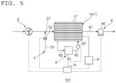
- An acid gas capture system 100 of the illustrated example includes an acid gas supply fan 2, a desorbed gas supply unit 5, a cooling gas supply unit 3, a capture unit 4, a thermometer 8, and a control part 9 in addition to the acid gas adsorption device.
- the acid gas capture system 100 of the illustrated example includes one of each of the acid gas adsorption device 1, the acid gas supply fan 2, the desorbed gas supply unit 5, the cooling gas supply unit 3, the capture unit 4, the thermometer 8, and the control part 9.
- the number of each of those components is not limited to any particular number as long as the number is one or more.
- the acid gas capture system 100 is a carbon dioxide capture system 100a including the carbon dioxide adsorption device 1a as an example of the acid gas adsorption device 1.
- the acid gas capture system 100 may include the acid gas adsorption device 7 (carbon dioxide adsorption device 7a ) in place of the acid gas adsorption device 1 (carbon dioxide adsorption device 1a ).
- the acid gas supply fan 2 is configured to supply the above-mentioned gas to be treated (typically, a CO 2 -containing gas) to the acid gas adsorption device 1 (typically, the acid gas adsorption part 19 ) in the adsorption step.
- the acid gas supply fan 2 of the illustrated example can send the gas to be treated containing the acid gas toward the acid gas adsorption device 1. Any appropriate configuration can be adopted for the acid gas supply fan 2.
- the acid gas supply fan 2 and the acid gas adsorption device 1 may be connected to each other through intermediation of a pipe or a part of a container that houses the acid gas adsorption device 1, which is located on an upstream side of the acid gas adsorption device 1.
- the desorbed gas supply unit 5 is configured to supply the above-mentioned desorbed gas to the acid gas adsorption device 1 (typically, the acid gas adsorption part 19 ) in the desorption step.
- the desorbed gas supply unit 5 of the illustrated example includes a desorbed gas supply line 51 and a first on-off valve 52.
- the desorbed gas supply line 51 is typically a pipe that allows the supply of the above-mentioned desorbed gas to the acid gas adsorption device 1.
- a downstream end portion of the desorbed gas supply line 51 in a direction of supply of the desorbed gas is connected to a part between the acid gas supply fan 2 and the acid gas adsorption device 1.
- an upstream end portion of the desorbed gas supply line 51 in the direction of supply of the desorbed gas is connected to an intermediate tank that stores the captured gas, although not shown.
- the first on-off valve 52 is provided to the desorbed gas supply line 51, and can open and close the desorbed gas supply line 51.
- the first on-off valve 52 include a ball valve, a gate valve, and a butterfly valve.
- the first on-off valve 52 is a butterfly valve.
- the cooling gas supply unit 3 is configured to supply the above-mentioned cooling gas to the acid gas adsorption device 1 (typically, the acid gas adsorption part 19 ) in the cooling step.
- the cooling gas supply unit 3 of the illustrated example includes a cooling gas device 30, a cooling gas supply line 31, and a second on-off valve 32.
- the cooling gas device 30 can produce and store the above-mentioned cooling gas.
- the cooling gas supply line 31 is typically a pipe that allows the supply of the above-mentioned cooling gas from the cooling gas device 30 to the acid gas adsorption device 1.
- the second on-off valve 32 is provided to the cooling gas supply line 31, and can open and close the cooling gas supply line 31.
- the second on-off valve 32 is, for example, similar to the first on-off valve 52 described above.
- the capture unit 4 is configured to capture the acid gas that has been desorbed in the desorption step.
- the capture unit 4 can capture the cooling gas that has passed through the acid gas adsorption device 1 (typically, the acid gas adsorption part 19 ) in the cooling step.
- the capture unit 4 of the illustrated example includes a suction pump 40 and a gas discharge portion 41.
- the suction pump 40 can suck the gas inside the acid gas adsorption device.
- the suction pump 40 is, for example, a vacuum pump.
- the gas discharge portion 41 may be a pipe or may be a part of the container that houses the acid gas adsorption device 1, which is located on a downstream side of the acid gas adsorption device.
- the method of capturing an acid gas includes the above-mentioned adsorption step, a replacement step, the above-mentioned desorption step, and the above-mentioned cooling step in the stated order.
- the acid gas adsorption device 1 includes the honeycomb-like base material 10a, the acid gas adsorption layers 15, and the heating member (not shown).
- the ranges of the temperature of the gas to be treated that is to be supplied to the acid gas adsorption device are the same as the above-mentioned ranges of the adsorption temperature.
- the temperature of the gas to be treated may be the same as or different from the adsorption temperature of the acid gas adsorption device.
- the pressure of the gas to be treated is, for example, 0.3 ⁇ 10 5 PaA (absolute pressure) or more and 2.0 ⁇ 10 5 PaA or less.
- the relative humidity RH of the gas to be treated is, for example, 10%RH or more and 60%RH or less.
- the flow velocity of the gas to be treated is, for example, 0.5 m/sec or more and 5 m/sec or less.
- the control part 9 monitors the temperature of the acid gas adsorption device 1 with use of the thermometer 8 so as to maintain the circulation of the liquid refrigerant until the acid gas adsorption device 1 is cooled to a desired cooling temperature. Also in this manner, the acid gas adsorption device after having undergone the desorption step can be smoothly cooled to thereby shorten the cooling time.
Landscapes
- Chemical & Material Sciences (AREA)
- Engineering & Computer Science (AREA)
- Analytical Chemistry (AREA)
- General Chemical & Material Sciences (AREA)
- Oil, Petroleum & Natural Gas (AREA)
- Chemical Kinetics & Catalysis (AREA)
- Separation Of Gases By Adsorption (AREA)
- Treating Waste Gases (AREA)
Applications Claiming Priority (2)
| Application Number | Priority Date | Filing Date | Title |
|---|---|---|---|
| JP2022139537 | 2022-09-01 | ||
| PCT/JP2023/031179 WO2024048566A1 (ja) | 2022-09-01 | 2023-08-29 | 酸性ガスの回収方法 |
Publications (1)
| Publication Number | Publication Date |
|---|---|
| EP4582165A1 true EP4582165A1 (en) | 2025-07-09 |
Family
ID=90099508
Family Applications (1)
| Application Number | Title | Priority Date | Filing Date |
|---|---|---|---|
| EP23860328.6A Pending EP4582165A1 (en) | 2022-09-01 | 2023-08-29 | Acid gas collection method |
Country Status (7)
| Country | Link |
|---|---|
| US (1) | US20250242289A1 (https=) |
| EP (1) | EP4582165A1 (https=) |
| JP (1) | JPWO2024048566A1 (https=) |
| CN (1) | CN119730938A (https=) |
| AU (1) | AU2023334810A1 (https=) |
| TW (1) | TW202417101A (https=) |
| WO (1) | WO2024048566A1 (https=) |
Families Citing this family (1)
| Publication number | Priority date | Publication date | Assignee | Title |
|---|---|---|---|---|
| DE102024123782A1 (de) * | 2024-08-20 | 2026-02-26 | Friedrich Boysen Gmbh & Co. Kg | Vorrichtung zum Abscheiden eines Stoffs aus einem Stoffgemisch |
Family Cites Families (8)
| Publication number | Priority date | Publication date | Assignee | Title |
|---|---|---|---|---|
| JPS602088B2 (ja) * | 1975-03-04 | 1985-01-19 | 東洋紡績株式会社 | 排ガスからの溶剤回収法 |
| JPS638413Y2 (https=) * | 1984-11-08 | 1988-03-14 | ||
| NO2986357T3 (https=) | 2013-04-18 | 2018-07-14 | ||
| EP3449997A1 (en) * | 2017-08-28 | 2019-03-06 | Casale Sa | A temperature-swing adsorption process |
| JP2021035654A (ja) * | 2017-10-10 | 2021-03-04 | 株式会社日立製作所 | Co2分離方法及び設備 |
| JP2019084489A (ja) * | 2017-11-06 | 2019-06-06 | 株式会社豊田中央研究所 | ガス分離装置 |
| WO2019147516A1 (en) * | 2018-01-24 | 2019-08-01 | Exxonmobil Upstream Research Company | Apparatus and system for temperature swing adsorption |
| JP7633795B2 (ja) * | 2020-10-20 | 2025-02-20 | イビデン株式会社 | 構造体及び該構造体を備えた二酸化炭素回収装置 |
-
2023
- 2023-08-29 WO PCT/JP2023/031179 patent/WO2024048566A1/ja not_active Ceased
- 2023-08-29 AU AU2023334810A patent/AU2023334810A1/en active Pending
- 2023-08-29 JP JP2024544274A patent/JPWO2024048566A1/ja active Pending
- 2023-08-29 EP EP23860328.6A patent/EP4582165A1/en active Pending
- 2023-08-29 CN CN202380059125.9A patent/CN119730938A/zh active Pending
- 2023-08-31 TW TW112132916A patent/TW202417101A/zh unknown
-
2025
- 2025-02-21 US US19/059,621 patent/US20250242289A1/en active Pending
Also Published As
| Publication number | Publication date |
|---|---|
| TW202417101A (zh) | 2024-05-01 |
| JPWO2024048566A1 (https=) | 2024-03-07 |
| US20250242289A1 (en) | 2025-07-31 |
| WO2024048566A1 (ja) | 2024-03-07 |
| CN119730938A (zh) | 2025-03-28 |
| AU2023334810A1 (en) | 2025-03-13 |
Similar Documents
| Publication | Publication Date | Title |
|---|---|---|
| US20250229213A1 (en) | Acid gas adsorption device | |
| CN104540584B (zh) | 选定的蜂窝通道表面上的不可渗透的聚合物涂层 | |
| US20250242292A1 (en) | Acid gas capture system | |
| US20250242289A1 (en) | Method of capturing an acid gas | |
| US20250242304A1 (en) | Method of capturing an acid gas | |
| US20250186931A1 (en) | Acid gas adsorption device | |
| US20260001026A1 (en) | Acid gas capture system and acid gas capture method | |
| US20260001027A1 (en) | Acid gas capture system and acid gas capture method | |
| TWI922928B (zh) | 酸性氣體回收系統及酸性氣體之回收方法 | |
| EP4582171A1 (en) | Acidic-gas adsorption device | |
| US20260091341A1 (en) | Acid gas adsorption device | |
| TWI916798B (zh) | 酸性氣體回收系統及酸性氣體之回收方法 | |
| WO2025088956A1 (ja) | 酸性ガス吸着装置 | |
| AU2024368117A1 (en) | Acidic gas adsorption device |
Legal Events
| Date | Code | Title | Description |
|---|---|---|---|
| STAA | Information on the status of an ep patent application or granted ep patent |
Free format text: STATUS: THE INTERNATIONAL PUBLICATION HAS BEEN MADE |
|
| PUAI | Public reference made under article 153(3) epc to a published international application that has entered the european phase |
Free format text: ORIGINAL CODE: 0009012 |
|
| STAA | Information on the status of an ep patent application or granted ep patent |
Free format text: STATUS: REQUEST FOR EXAMINATION WAS MADE |
|
| 17P | Request for examination filed |
Effective date: 20250401 |
|
| AK | Designated contracting states |
Kind code of ref document: A1 Designated state(s): AL AT BE BG CH CY CZ DE DK EE ES FI FR GB GR HR HU IE IS IT LI LT LU LV MC ME MK MT NL NO PL PT RO RS SE SI SK SM TR |
|
| DAV | Request for validation of the european patent (deleted) | ||
| DAX | Request for extension of the european patent (deleted) |