EP4582164A2 - Flüssig-gas-separator - Google Patents
Flüssig-gas-separator Download PDFInfo
- Publication number
- EP4582164A2 EP4582164A2 EP25164579.2A EP25164579A EP4582164A2 EP 4582164 A2 EP4582164 A2 EP 4582164A2 EP 25164579 A EP25164579 A EP 25164579A EP 4582164 A2 EP4582164 A2 EP 4582164A2
- Authority
- EP
- European Patent Office
- Prior art keywords
- flow
- separator
- suction
- port
- matter
- Prior art date
- Legal status (The legal status is an assumption and is not a legal conclusion. Google has not performed a legal analysis and makes no representation as to the accuracy of the status listed.)
- Pending
Links
Images




















Classifications
-
- A—HUMAN NECESSITIES
- A61—MEDICAL OR VETERINARY SCIENCE; HYGIENE
- A61M—DEVICES FOR INTRODUCING MEDIA INTO, OR ONTO, THE BODY; DEVICES FOR TRANSDUCING BODY MEDIA OR FOR TAKING MEDIA FROM THE BODY; DEVICES FOR PRODUCING OR ENDING SLEEP OR STUPOR
- A61M1/00—Suction or pumping devices for medical purposes; Devices for carrying-off, for treatment of, or for carrying-over, body-liquids; Drainage systems
- A61M1/71—Suction drainage systems
- A61M1/76—Handpieces
-
- A—HUMAN NECESSITIES
- A61—MEDICAL OR VETERINARY SCIENCE; HYGIENE
- A61M—DEVICES FOR INTRODUCING MEDIA INTO, OR ONTO, THE BODY; DEVICES FOR TRANSDUCING BODY MEDIA OR FOR TAKING MEDIA FROM THE BODY; DEVICES FOR PRODUCING OR ENDING SLEEP OR STUPOR
- A61M1/00—Suction or pumping devices for medical purposes; Devices for carrying-off, for treatment of, or for carrying-over, body-liquids; Drainage systems
- A61M1/71—Suction drainage systems
- A61M1/79—Filters for solid matter
-
- A—HUMAN NECESSITIES
- A61—MEDICAL OR VETERINARY SCIENCE; HYGIENE
- A61M—DEVICES FOR INTRODUCING MEDIA INTO, OR ONTO, THE BODY; DEVICES FOR TRANSDUCING BODY MEDIA OR FOR TAKING MEDIA FROM THE BODY; DEVICES FOR PRODUCING OR ENDING SLEEP OR STUPOR
- A61M1/00—Suction or pumping devices for medical purposes; Devices for carrying-off, for treatment of, or for carrying-over, body-liquids; Drainage systems
- A61M1/84—Drainage tubes; Aspiration tips
-
- A—HUMAN NECESSITIES
- A61—MEDICAL OR VETERINARY SCIENCE; HYGIENE
- A61M—DEVICES FOR INTRODUCING MEDIA INTO, OR ONTO, THE BODY; DEVICES FOR TRANSDUCING BODY MEDIA OR FOR TAKING MEDIA FROM THE BODY; DEVICES FOR PRODUCING OR ENDING SLEEP OR STUPOR
- A61M1/00—Suction or pumping devices for medical purposes; Devices for carrying-off, for treatment of, or for carrying-over, body-liquids; Drainage systems
- A61M1/88—Draining devices having means for processing the drained fluid, e.g. an absorber
-
- B—PERFORMING OPERATIONS; TRANSPORTING
- B01—PHYSICAL OR CHEMICAL PROCESSES OR APPARATUS IN GENERAL
- B01D—SEPARATION
- B01D19/00—Degasification of liquids
- B01D19/0036—Flash degasification
-
- B—PERFORMING OPERATIONS; TRANSPORTING
- B01—PHYSICAL OR CHEMICAL PROCESSES OR APPARATUS IN GENERAL
- B01D—SEPARATION
- B01D19/00—Degasification of liquids
- B01D19/0042—Degasification of liquids modifying the liquid flow
-
- B—PERFORMING OPERATIONS; TRANSPORTING
- B01—PHYSICAL OR CHEMICAL PROCESSES OR APPARATUS IN GENERAL
- B01D—SEPARATION
- B01D19/00—Degasification of liquids
- B01D19/0042—Degasification of liquids modifying the liquid flow
- B01D19/0052—Degasification of liquids modifying the liquid flow in rotating vessels, vessels containing movable parts or in which centrifugal movement is caused
- B01D19/0057—Degasification of liquids modifying the liquid flow in rotating vessels, vessels containing movable parts or in which centrifugal movement is caused the centrifugal movement being caused by a vortex, e.g. using a cyclone, or by a tangential inlet
-
- B—PERFORMING OPERATIONS; TRANSPORTING
- B01—PHYSICAL OR CHEMICAL PROCESSES OR APPARATUS IN GENERAL
- B01D—SEPARATION
- B01D19/00—Degasification of liquids
- B01D19/0073—Degasification of liquids by a method not covered by groups B01D19/0005 - B01D19/0042
- B01D19/0094—Degasification of liquids by a method not covered by groups B01D19/0005 - B01D19/0042 by using a vortex, cavitation
-
- B—PERFORMING OPERATIONS; TRANSPORTING
- B01—PHYSICAL OR CHEMICAL PROCESSES OR APPARATUS IN GENERAL
- B01D—SEPARATION
- B01D35/00—Filtering devices having features not specifically covered by groups B01D24/00 - B01D33/00, or for applications not specifically covered by groups B01D24/00 - B01D33/00; Auxiliary devices for filtration; Filter housing constructions
- B01D35/02—Filters adapted for location in special places, e.g. pipe-lines, pumps, stop-cocks
-
- B—PERFORMING OPERATIONS; TRANSPORTING
- B01—PHYSICAL OR CHEMICAL PROCESSES OR APPARATUS IN GENERAL
- B01D—SEPARATION
- B01D45/00—Separating dispersed particles from gases or vapours by gravity, inertia, or centrifugal forces
- B01D45/12—Separating dispersed particles from gases or vapours by gravity, inertia, or centrifugal forces by centrifugal forces
- B01D45/16—Separating dispersed particles from gases or vapours by gravity, inertia, or centrifugal forces by centrifugal forces generated by the winding course of the gas stream, the centrifugal forces being generated solely or partly by mechanical means, e.g. fixed swirl vanes
-
- B—PERFORMING OPERATIONS; TRANSPORTING
- B01—PHYSICAL OR CHEMICAL PROCESSES OR APPARATUS IN GENERAL
- B01D—SEPARATION
- B01D46/00—Filters or filtering processes specially modified for separating dispersed particles from gases or vapours
- B01D46/0027—Filters or filtering processes specially modified for separating dispersed particles from gases or vapours with additional separating or treating functions
-
- A—HUMAN NECESSITIES
- A61—MEDICAL OR VETERINARY SCIENCE; HYGIENE
- A61M—DEVICES FOR INTRODUCING MEDIA INTO, OR ONTO, THE BODY; DEVICES FOR TRANSDUCING BODY MEDIA OR FOR TAKING MEDIA FROM THE BODY; DEVICES FOR PRODUCING OR ENDING SLEEP OR STUPOR
- A61M2205/00—General characteristics of the apparatus
- A61M2205/75—General characteristics of the apparatus with filters
- A61M2205/7509—General characteristics of the apparatus with filters for virus
-
- A—HUMAN NECESSITIES
- A61—MEDICAL OR VETERINARY SCIENCE; HYGIENE
- A61M—DEVICES FOR INTRODUCING MEDIA INTO, OR ONTO, THE BODY; DEVICES FOR TRANSDUCING BODY MEDIA OR FOR TAKING MEDIA FROM THE BODY; DEVICES FOR PRODUCING OR ENDING SLEEP OR STUPOR
- A61M2205/00—General characteristics of the apparatus
- A61M2205/75—General characteristics of the apparatus with filters
- A61M2205/7518—General characteristics of the apparatus with filters bacterial
-
- A—HUMAN NECESSITIES
- A61—MEDICAL OR VETERINARY SCIENCE; HYGIENE
- A61M—DEVICES FOR INTRODUCING MEDIA INTO, OR ONTO, THE BODY; DEVICES FOR TRANSDUCING BODY MEDIA OR FOR TAKING MEDIA FROM THE BODY; DEVICES FOR PRODUCING OR ENDING SLEEP OR STUPOR
- A61M2206/00—Characteristics of a physical parameter; associated device therefor
- A61M2206/10—Flow characteristics
- A61M2206/16—Rotating swirling helical flow, e.g. by tangential inflows
Definitions
- Suction products suctioned from a field may comprise mixtures of solids, liquids, and gases.
- An aspect of the present disclosure provides a system for separation a flow of matter.
- the system comprises a flow separation device, a surgical instrument, and a suction source.
- the flow separation device comprises (a) a hollow body comprising a first end, a second end, and an inner volume therebetween; (b) a suction port disposed at the first end; (c) a collection port disposed at the second end; (d) an input port disposed between the first end and the second end and fluidically connected to the inner volume; (e) one or more baffles disposed within the inner volume between the first end and the second end; and (f) a shaft disposed within the inner volume.
- the input port is configured to receive a flow of matter comprising a gas, a liquid, a solid, or combination thereof.
- the shaft is configured to direct the flow of matter received into the hollow body.
- at least a portion of a liquid of the flow of matter exits the hollow body from a port different than a port from which at least a portion of a gas of the flow of matter exits.
- the shaft directs at least a portion of the flow of matter in a cyclonic pattern along an inner surface of the hollow body.
- the gas exits the suction port and the liquid exits the collection port.
- the one or more baffles are configured to prevent the flow of matter from passing directly from the input port to the suction port without first traversing at least a portion of the circumference of the inner surface.
- the one or more baffles comprise a plurality of openings configured to receive at least a portion of the flow of matter.
- the plurality of openings is distal to the input port.
- the one or more baffles comprise a tapered section or comprise a plurality of cylindrical sections having different diameters.
- the second end comprises a conical shape.
- the hollow body comprises a cylindrical shape.
- the flow of matter comprises surgical waste.
- the flow of matter comprises biological material.
- the input port is proximal to the suction port and distal from the collection port.
- the suction port is configured to couple to the suction source.
- the suction source is a passive suction source.
- the collection port is configured to couple to a collection container.
- the flow separation device is attachable or formed therein a collection container.
- the one or more baffles aids in the separation of gas, of liquid, or a combination thereof from the flow of matter.
- the input port forms an angle relative to a central axis of the hollow body that is less than 90 degrees. In some embodiments, the angled input port enhances entry of the flow of matter into the input port, enhances a cyclonic pattern of flow along an inner surface of the hollow body, or a combination thereof.
- the baffle comprises a plurality of openings to allow passage of the flow of matter, comprising separated portions thereof, out of the suction port.
- the baffle comprises a solid surface located proximal to the input port and distal to the plurality of openings, configured to prevent the flow of matter, comprising separated portions thereof, from passing directly from the input port to the suction port without first traversing at least a portion of a circumference of the cylindrical cavity wall.
- the method further comprises locating the input port off-axis of an axis defined by a longitudinal center of the separator body. In some embodiments, the method further comprises locating the input port closer to the first cylindrical end than the second cylindrical end. In some embodiments, the method further comprises providing the suction source using a vacuum pump.
- the separator comprises: (a) a cylindrical cavity comprising a cylindrical cavity wall, a first cylindrical cavity end, and a second cylindrical cavity end, the separator configured to operate with the first cylindrical cavity end being up; (b) a suction port to be coupled to a suction source, the suction port being in the first cylindrical cavity end; (c) a conical cavity, the conical cavity comprising a wide end and a narrow end, the wide end being mated to the second cylindrical cavity end; (d) a collection port at the narrow end of the conical cavity; (e) an input port to receive a flow of matter comprising a mixture of liquid and gas, the input port being in the cylindrical cavity wall, the flow of matter induced into the separator by the suction source, the input port configured to direct liquids in the flow the matter to cling to the cylindrical cavity wall; (f) a baffle disposed between the input port and the suction port, the baffle configured to prevent liquid
- the flow of matter further comprises solids, the solids in the flow of matter pass through the annular cavity before dropping out the collection port.
- the baffle comprises a plurality of openings to allow the gasses in the flow of matter to be pulled out of the separator via the suction port.
- the baffle comprises a solid portion that prevents liquids in the flow of matter from being pulled directly from the input port to the suction port, the solid portion corresponding to at least the first portion of the circumference.
- the central member comprises a tapered section disposed in the conical cavity. In some embodiments, the central member comprises a plurality of cylindrical sections comprising different diameters.
- a plurality of cylindrical sections includes a first section that defines a first portion of the annular cavity and a second section that defines a second portion of the annular cavity.
- the first portion is disposed between the baffle and the second portion, the second portion is disposed between the first portion and the conical cavity.
- the central member further comprises a tapered section disposed in the conical cavity thereby forming a hollow cone shaped cavity, the hollow cone shaped cavity disposed between the second portion and the second port.
- the method comprises: (a) providing a cylindrical cavity having a cylindrical cavity wall, a first cylindrical cavity end, and a second cylindrical cavity end, and operating the separator with the first cylindrical cavity end being up; (b) coupling a suction port to a suction source, the suction port being in the first cylindrical cavity end; (c) providing a conical cavity, the conical cavity having a wide end and a narrow end, and mating the wide end to the second cylindrical cavity end; (d) providing a collection port at the narrow end of the conical cavity; (e) receiving a flow comprising a mixture of liquid and gas at a input port, the input port being in the cylindrical cavity wall, and inducing the flow into the separator by the suction source, directing liquids in the flow to cling to the cylindrical cavity wall by configuring the input port; (f) providing a baffle disposed between the input port and the suction port, thereby preventing liquid
- the method further comprises providing a flow further comprising solids and passing the solids in the flow through the annular cavity before dropping out the collection port.
- the method further comprises providing the baffle comprising a plurality of openings to allow the gasses in the flow to be pulled out of the separator via the suction port.
- the method further comprises preventing liquids in the flow from being pulled directly from the input port to the suction port by providing the baffle comprising a solid portion, the solid portion corresponding to at least the first portion of the circumference.
- the method further comprises providing the central member comprising a tapered section disposed in the conical cavity. In some embodiments, the method further comprises providing the central member comprising a plurality of cylindrical sections comprising different diameters. In some embodiments, the method further comprises providing a plurality of cylindrical sections comprising a first section defining a first portion of the annular cavity and a second section defining a second portion of the annular cavity.
- the method further comprises disposing the first portion between the baffle and the second portion and disposing the second portion between the first portion and the conical cavity. In some embodiments, the method further comprises providing the central member a tapered section disposed in the conical cavity thereby forming a hollow cone shaped cavity and disposing the hollow cone shaped cavity between the second portion and the collection port.
- the flow separator comprises: (a) a cylindrical cavity comprising a cylindrical wall comprising a first end and a second end, the first end disposed in an upward position, and means for directing a flow of matter along a circumference of the cylindrical cavity wall; (b) an input port mated to the cylindrical cavity wall, and means for receiving the flow of matter and directing the flow of matter into the cylindrical cavity; (c) an suction port mated to the first end of the cylindrical cavity, and means for coupling the separator to a suction source; (d) the suction port comprising means for expelling at least gasses out of the separator; (e) a conical cavity comprising a wide end and a narrow end and a conical cavity wall, the wide end mated to the second end of the cylindrical cavity, and a means for directing the flow of matter to create a flow within the cylindrical cavity whereby gasses are directed out of the suction port and at least liquids are directed out
- the flow of matter comprises one or more of liquids, solids and gasses, and means for the liquids and/or solids to pass through the annular cavity and out of the collection port.
- the central member comprises a tapered section disposed in the conical cavity, and means for directing the flow of matter within the separator. In some embodiments, the central member comprises a plurality of cylindrical sections comprising different diameters, and means for directing the flow of matter within the separator.
- a plurality of cylindrical sections include a first section that defines a first portion of the annular cavity and a second section that defines a second portion of the annular cavity, and means for directing the flow of matter within the separator.
- the first portion is disposed between the baffle and the second portion
- the second portion is disposed between the first portion and the conical cavity, and means for directing the flow of matter within the separator.
- the central member further comprises a tapered section disposed in the conical cavity thereby forming a hollow cone shaped cavity, the hollow cone shaped cavity disposed between the second portion and the collection port, and means for directing the flow of matter through the hollow cone shaped cavity.
- the system comprises: (a) one or more separators comprising: (i) a cylindrical cavity comprising a cylindrical wall comprising a first end and a second end, the first end disposed in an upward position, and means for directing a flow of matter along the circumference of the cylindrical cavity wall; (ii) an input port mated to the cylindrical cavity wall, and means for receiving the flow of matter and directing the flow of matter into the cylindrical cavity; (iii) an suction port mated to the first end of the cylindrical cavity, and means for coupling the separator to a suction source; (iv) the suction port comprising means for expelling at least gasses out of the separator; (v) a conical cavity comprising a wide end and a narrow end and a conical cavity wall, the wide end mated to the second end of the cylindrical cavity, and a means for directing the flow of matter to create a flow within the cylindrical cavity whereby
- the flow of matter comprises one or more of liquids, solids and gasses, and means for the liquids and/or solids to pass through the annular cavity and out of the collection port.
- the baffle comprises a plurality of openings, and means for allowing matter to pass through the baffle and out the suction port after traversing at least a portion of the circumference of the cylindrical cavity wall.
- the baffle comprises a solid portion disposed proximally to the input port, and means for preventing liquids and/or solids in the flow from being pulled directly from the input port to the suction port before traversing at least a portion of the circumference of the cylindrical cavity wall.
- the central member comprises a tapered section disposed in the conical cavity, and means for directing the flow of matter within the separator. In some embodiments, the central member comprises a plurality of cylindrical sections comprising different diameters, and means for directing the flow of matter within the separator.
- the second end comprises a conical shape. In some embodiments, the hollow body comprises a cylindrical shape. In some embodiments, the flow of matter comprises surgical waste. In some embodiments, the flow of matter comprises biological material.
- the input port is proximal to the suction port and distal from the collection port.
- the suction port is configured to couple to the suction source.
- the suction source is a passive suction source.
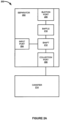
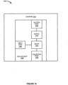
- FIG. 1 is a block diagram illustrating separator 100.
- separator 100 is configured to separate liquids, solids and gasses in a flow of matter.
- Separator 100 ejects liquids and/or solids separated from the flow of matter out collection port 108 while suctioning at least gasses separated from the flow of matter out suction port 106.
- Separator 100 is operated by suction received from a suction source. It should be understood that the terms "suction” and “vacuum” as used herein refer to a pressure below the surrounding ambient air pressure.
- separator 100 comprises hollow body 102, input port 104, suction port 106, collection port 108, baffle 110, and shaft 112.
- hollow body 102 comprises a cylindrical wall defining a cylindrical cavity.
- Other hollow body 102 shapes are suitable for use with the separator 100 including conical shapes and ovoid cylindrical shapes.
- the hollow body 102 wall may include a first cavity end and a second cavity end.
- the cavity of hollow body 102 may have a wide end and a narrow end.
- Hollow body 102 is constructed of a single solid wall that is formed into the hollow body 102 shape, or alternatively, a first wide end of hollow body 102 is mated to a second narrow end of hollow body 102 to form a single hollow body 102 having a narrow section and wide section.
- hollow body 102 is configured to operate in an orientation with the first cavity end up.
- Hollow body 102 is configured to be oriented in operation to allow gravity to pull at least liquid and solids separated from a flow of matter out collection port 108, while gasses separated from the flow of matter are pulled by suction out of suction port 106.
- Input port 104 is configured and positioned to direct a flow of matter received into the hollow body 102 along the internal cavity wall of the hollow body 102. Because, in some embodiments, the hollow body 102 comprises a cylindrical, spherical, or ovoid cylindrical shape, the flow generated within the cavity of the hollow body 102 comprises and essentially cyclonic flow pattern.
- suction port 106 further comprises a check valve mechanism (not shown in FIG. 1 ) to, for example, prevent the flow of solids or liquids through suction port 106.
- Suction port 106 is configured to couple to a suction source.
- the suction source may include, for example, a vacuum pump, aspirator, and/or a positive pressure operated suction source-such as suction sources that take advantage of Venturi or Coanda effect.
- Suction from a suction source is transferred from suction port 106 to input port 104.
- Suction port 106 is disposed near the first cavity end of the hollow body 102.
- Suction port 106 provides suction received from a suction source for operating separator 100 and may further comprise a check valve.
- suction port 106 includes fittings configured to attach tubing. For example, barbed or quick-disconnect type fittings are used to couple tubing to suction port 106.
- the tubing is, for example, used to couple suction port 106 to a suction source or to an input port 104 of another separator.
- Collection port 108 is configured to expel at least liquids and/or solids. Collection port 108 is disposed at the narrow end of the conical cavity of hollow body 102. In some embodiments, collection port 108 is configured to couple to a canister. A canister is used to collect and measure matter received from separator 100. A canister may also be used for the safe collection, transportation and disposal of waste received from separator 100. In some embodiments, collection port 108 is coupled to tubing or piping to direct matter to a waste drain. In some embodiments, collection port 108 may include a mounting ring configured to form a seal between collection port 108 to tubing or a canister.
- Baffle 110 is disposed between input port 104 and suction port 106.
- Baffle 110 is configured to facilitate a cyclonic flow of matter within the hollow cavity 100 by preventing liquids and/or solids in the flow from being pulled directly from input port 104 to suction port 106 without traversing at least a first portion of a circumference of the cylindrical wall of hollow body 102.
- baffle 110 includes openings configured to allow at least gasses in a flow of matter to separate from liquids and/or solids that are included in the flow. One or more gasses are pulled through baffle 110 and out suction port 106.
- baffle 110 includes a solid surface located proximal to input port 104.
- the solid surface portion of the baffle 110 is thus configured to prevent suction of liquid and/or solid matter out of suction port 106 while allowing time for gravity to act on the liquids and/or solids as they traverse the solid surface of baffle 110.
- the effect of gravity within the cavity of the hollow body 102 on liquids and/or solids causes them to generally descend (within the input flow) towards collection port 108 and thereby not be suctioned out of the suction port 106.
- Shaft 112 is configured to direct a flow of matter in a cyclonic flow.
- the cyclonic flow along with gravity cause liquids and solids to separate from gasses included in the flow of matter.
- shaft 112 includes a member disposed within the cylindrical cavity of hollow body 102.
- the member of shaft 112 is positioned within the cavity of hollow body 102 so that the cavity of hollow body 102 surrounding the central member of shaft 112 comprises an annular cavity shape between shaft 112 and hollow body 102 cavity wall.
- Shaft 112 is configured to direct liquids and/or solids that are in the flow so that they pass through the annular cavity between the shaft 112 and hollow body 102 cavity wall before dropping out collection port 108.
- shaft 112 includes a tapered section or conical end disposed in the cavity of hollow body 102.
- shaft 112 includes a plurality of sections having different diameters. The plurality of sections, for example, include a first cylindrical section that defines a first portion of the annular section of the cavity the hollow body 102 and a second section that defines a second portion of the annular cavity. Tapered and cylindrical sections of shaft 112 are configured to direct the flow within hollow body 102 in a cyclonic flow pattern.
- baffle 110 is integral to shaft 112.
- FIG. 2A is a block diagram illustrating separator and canister system 200.
- Separator 202 is an example of separator 100; however, separator 202 may include alternative configurations and methods of operation.
- Separator and canister system 200 may include separator 202 and canister 214.
- separator 202 comprises input port 204, suction port 206, collection port 208, baffle 210 and shaft 212.
- separator 202 comprises a generally cylindrical cavity and a cavity wall.
- suitable cavity shapes for separator 202 include spherical and ovoid cylindrical shapes.
- Separator 202 is configured to generate a vortex flow within the cavity of separator 202.
- the cavity of separator 202 includes a first end and a second cavity end.
- the cavity is configured to have a wide end and a narrow end. The wide end is coupled to the second end of the generally cavity.
- the separator 202 is configured to operate with the first end positioned upwards.
- Input port 204 is configured to direct a flow of matter into separator 202. Input port 204 also directs the flow of matter towards shaft 212.
- the flow of matter may include liquids, solids and gasses, including combinations thereof in varying ratios. Some constituents of the flow of matter may include surgical byproducts.
- a flow of matter is induced into input port 204 by suction received from a suction source.
- input port 204 is integral to separator 202.
- Input port 204 is disposed in the cavity wall near the first end of the generally cylindrical cavity of separator 202. Input port 204 is disposed off-axis from an axis defined by the longitudinal center of the generally cylindrical cavity of the body.
- input port 204 may include fittings such as, barbed or quick-disconnect type fittings, for coupling input port 204 to a suction tip or surgical device.
- input port 204 is configured and positioned to generate a vortex of flow within the cavity of the separator 202.
- Shaft 212 is configured to form an annular cavity between shaft 212 and separator 202 within the cavity of separator 202.
- shaft 212 includes a cylindrical central member disposed within the generally cylindrical cavity of separator 202.
- Shaft 212 is configured to generate a vortex flow within separator 202. The vortex flow and gravity cause liquids and/or solids in a flow of matter received at input port 204 to separate from gasses. Liquids and gases within the matter flow are expelled out suction port 206.
- shaft 212 may include a tapered section disposed near the conical cavity of separator 202.
- shaft 212 may include a plurality of cylindrical sections having different diameters.
- the plurality of cylindrical sections may include a first section that defines a first portion of the annular cavity and a second section that defines a second portion of the annular cavity.
- baffle 210 is integral to shaft 212.
- Canister 214 is configured to receive waste from separator 202.
- the waste may include at least liquids and/or solids separated from a flow of matter received at input port 204.
- Canister 214 is used to measure the amount of liquids and/or solids separated from the flow of matter received at input port 204.
- Canister 214 is configured to permit the safe collection, transportation and disposal of waste.
- canister 214 may include a valve configured to activate when canister 214 is filled to a pre-determined volume. The valve is used to prevent waste from leaving canister 214 during transportation.
- canister 214 may include a commercially available canister.
- the systems, devices, and methods described herein are configured to separate a gas from a liquid at a controlled rate.
- the controlled rate of suction applied by a system increases when one or more flow separation devices are connected as described herein.
- two or more separators in a system are connected "in series" so that suction from a suction source is transmitted from a first separator to a second separator connected to the first separator as described herein.
- one or more separators are in a system connected "in parallel" such that two or more interconnected separators (connected to each other as described) are both connected to one or more suction sources.
- a flow rate may be generated of at least about 1 cubic centimeter per second (cc/s), 2 cc/s, 3 cc/s, 4 cc/s, 5 cc/s, 6 cc/s, 7 cc/s, 8 cc/s, 9 cc/s, 10 cc/s, 11 cc/s, 12 cc/s, 13 cc/s, 14 cc/s, 15 cc/s, 16 cc/s, 17 cc/s, 18 cc/s, 19 cc/s, 20 cc/s, 25 cc/s, 30 cc/s, 35 cc/s, 40 cc/s, 45 cc/s, 50 cc/s, 55 cc/s, 60 cc/s, 65 cc/s, 70 cc/s, 75 cc/s, 80 cc/s,
- the system may separate gas from liquid at a rate of at least about 5 cc/s.
- the system may separate gas from liquid at a rate of at least about 10 cc/s.
- the system may separate gas from liquid at a rate of at least about 20 cc/s.
- the system may separate gas from liquid at a rate of at least about 30 cc/s.
- the system may separate gas from liquid at a rate of at least about 40 cc/s.
- the system may separate gas from liquid as a rate of at least about 50 cc/s.
- the one or more flow separation devices as described herein may provide a separation of a flow, such as a separation of a gas and liquid in a flow at a flow rate of about 100 mmHg, 150 mmHg, 200 mmHg, 250 mmHg, 300 mmHg, 350 mmHg, 400 mmHg, 450 mmHg, 500 mmHg, or more.
- a separate of a flow may occur at a flow rate of at least about 150 mmHg.
- a separation of a flow may occur at a flow rate of at least about 200 mmHg.
- a separation of a flow may occur at a flow rate of at least about 250 mmHg.
- a separation of a flow may occur at a flow rate of at least about 300 mmHg.
- a separation of a flow may occur at a flow rate of at least about 350 mmHg.
- a separation of a flow may occur at a flow rate of at least about 400 mmHg.
- a separation of a flow may occur at a flow rate of at least about 500 mmHg.
- a separation of a flow may occur at a flow rate from about 150 mmHg to about 350 mmHg.
- a separation of a flow may occur at a flow rate from about 200 mmHg to about 350 mmHg.
- the one or more flow separation devices as described herein may be configured to cyclone a liquid portion of a flow into an outlet port adjacent or attached to canister and to divert a gas portion of a flow through a separate outlet port such as to a filtration device.
- the one or more flow separation devices or one or more components of the separation device may be disposable.
- the one or more flow separation devices or one or more components of the separation device may be reusable.
- the suction capacity of a surgical instrument operatively coupled to one or more flow separation devices may increase compared to a surgical instrument not operatively coupled.
- the suction capacity may increase about 1 fold, 1.25 fold, 1.5 fold, 1.75 fold, 2 fold, 2.25 fold, 2.5 fold, 2.75 fold, 3 fold, 3.25 fold, 3.5 fold, 3.75 fold, 4 fold, 4.25 fold, 4.5 fold, 4.75 fold, 5 fold, or more.
- the suction capacity may increase by at least about 1.25 fold.
- the suction capacity may increase by at least about 1.5 fold.
- the suction capacity may increase by at least about 1.75 fold.
- the suction capacity may increase by at least about 2 fold.
- the suction capacity may increase by at least about 2.5 fold.
- the suction capacity may increase by at least about 3 fold.
- the suction capacity of a surgical instrument operatively coupled to one or more flow separation devices may increase compared to a surgical instrument not operatively coupled.
- the suction capacity may increase about 20%, 25%, 30%, 35%, 40%, 45%, 50%, 55%, 60%, 65%, 70%, 75%, 80%, 85%, 90%, 95% or more.
- the suction capacity may increase at least about 25%.
- the suction capacity may increase at least about 30%.
- the suction capacity may increase at least about 35%.
- the suction capacity may increase at least about 40%.
- the suction capacity may increase at least about 45%.
- the suction capacity may increase at least about 50%.
- the suction capacity may increase at least about 55%.
- the suction capacity may increase at least about 60%.
- the suction capacity may increase at least about 65%.
- the suction capacity may increase at least about 70%.
- the suction capacity may increase at least about 75%.
- the suction capacity may increase at least about 80%.
- the suction capacity
- the suction capacity of a suction source such as a passive suction source, operatively coupled to one or more flow separation devices may increase compared to a suction source not operatively coupled.
- the suction capacity may increase about 1 fold, 1.25 fold, 1.5 fold, 1.75 fold, 2 fold, 2.25 fold, 2.5 fold, 2.75 fold, 3 fold, 3.25 fold, 3.5 fold, 3.75 fold, 4 fold, 4.25 fold, 4.5 fold, 4.75 fold, 5 fold, or more.
- the suction capacity may increase by at least about 1.25 fold.
- the suction capacity may increase by at least about 1.5 fold.
- the suction capacity may increase by at least about 1.75 fold.
- the suction capacity may increase by at least about 2 fold.
- the suction capacity may increase by at least about 2.5 fold.
- the suction capacity may increase by at least about 3 fold.
- the suction capacity of a suction source such as a passive suction source, operatively coupled to one or more flow separation devices may increase compared to a suction source not operatively coupled.
- the suction capacity may increase about 20%, 25%, 30%, 35%, 40%, 45%, 50%, 55%, 60%, 65%, 70%, 75%, 80%, 85%, 90%, 95% or more.
- the suction capacity may increase at least about 25%.
- the suction capacity may increase at least about 30%.
- the suction capacity may increase at least about 35%.
- the suction capacity may increase at least about 40%.
- the suction capacity may increase at least about 45%.
- the suction capacity may increase at least about 50%.
- the suction capacity may increase at least about 55%.
- the suction capacity may increase at least about 60%.
- the suction capacity may increase at least about 65%.
- the suction capacity may increase at least about 70%.
- the suction capacity may increase at least about 75%.
- the suction capacity may increase at least about 80%.
- the suction capacity may increase at least about 85%.
- the suction capacity may increase at least about 90%.
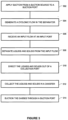
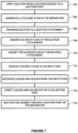
- FIG. 5 is a diagram illustrating an exemplary method of operating a separator system in series. The steps illustrated in FIG. 5 is performed by, for example, one or more elements of separator system 400.
- a single suction source applies suction to a suction port of a second separator which is connected to a first separator.
- the first separator is connected to the second separator such that a suction flow generated within the second separator is translated to the first separator.
- the input port of the second separator is connected to the suction port of the first separator by a suction conduit such as standard suction tubing.
- a suction source is directly applied to a suction port of a second separator generating a suction flow that is transmitted to the first separator.
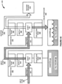
- suction source 416 is configured to supply suction.
- Suction port 426 is configured to receive suction flow 442 from suction source 416.
- Separator 422 is configured to transfer suction flow 442 from input port 424 to suction port 406.
- a cyclonic or vortex flow is generated in both separators.
- the first and second separators are configured, as described herein, to generate a cyclonic or vortex suction flow when a suction source is applied to both separators.
- separators 402, 422 are configured to generate from suction flow 442, a cyclonic flow of matter that is received via input port 404.
- an input flow is received at an input port of the first separator.
- input port 404 is configured to receive input flow 440.
- Suction flow 442 has a pressure below an ambient air pressure. This pressure difference is configured to cause input flow 440 to flow into input port 404.
- a step 510 liquids and/or solids is separated from the input flow at the first separator as a suction flow is transmitted from the second separator.
- separator 402 is configured to separate suction flow 442 by directing the heavier constituents (i.e., liquids and solids) of input flow 440 into a cyclonic flow pattern that gravity acts upon to cause these heavier constituents to exit via collection port 408, while the lighter constituents (i.e., gasses, smoke, aerosols) in input flow 440 are pulled out of separator 402 by the suction at suction port 406.
- collection flow 444 includes at least liquids and solids.
- a collection port is configured to receive the heavier constituents and direct them to a canister.
- collection port 408 is configured to receive the heavier constituents and direct them to collection canister 414.
- Separator 402 is coupled to collection canister 414.
- Collection canister 414 is configured to receive collection flow 444 from collection port 408.
- Separator 402 is configured to expel collection flow 444 to collection canister 414 so long as fill volume 436 has not reached a predetermined level.
- a step 520 liquids and/or solids is separated from the input flow at the second separator.
- separator 422 is configured to separate suction flow 442 from collection flow 444.
- Suction flow 442 may comprise primarily gasses separated from input flow 440.
- Collection flow 444 may comprise primarily liquids and/or solids separated from input flow 440.
- suction flow 442 may comprise primarily gasses separated from input flow 440.
- Separator 422 is configured to pass suction flow 442 through suction port 426.
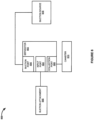
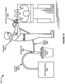
- FIG. 6 is a block diagram illustrating suction system 600.
- Suction system 600 includes separator 602, collection canister 614, suction source 616 and suction attachment 646.
- Separator 602 is an example of separator 100, separator 202, separator 402 and separator 422; however, separator 602 may include alternative configurations and methods of operation.
- Collection canister 614 is an example of collection canister 214, collection canister 414 and collection canister 434; however, collection canister 614 may include alternative configurations and methods of operation.
- Suction source 616 is an example of suction source 416; however, suction source 616 may include alternative configurations or methods of operation.
- separator 602 includes input port 604, suction port 606 and collection port 608.
- input port 604 is integral to a body included as part of separator 602.
- Input port 604 may integral to separator 602.
- Input port 604 is located off-axis from an axis defined by the longitudinal center of the cylindrical cavity.
- Input port 604 may be configured to direct a flow of matter along the cylindrical cavity wall. By directing the flow of matter along the cylindrical cavity wall, liquids and gasses may cling to the wall of the cavity due to the effects of centripetal forces.
- Input port 604 is configured to receive a flow of matter. The flow of matter is pulled into input port 604 by the pressure difference between the ambient air pressure and the lower pressure provided by suction source 616.
- input port 604 may include fittings configured to attach tubing. For example, barbed or quick-disconnect type fittings may be used to couple tubing to input port 604.
- Collection port 608 is configured to expel a collection flow.
- the collection flow may include at least liquids and solids.
- Collection port 608 is disposed at the narrow end of the conical cavity of separator 602.
- Collection port 608 is coupled to collection canister 614.
- Collection canister 614 may be used to measure the matter collected from separator 602.
- Collection canister 614 may also be used for the safe collection, transportation, and disposal of waste received from separator 602.
- collection port 608 may include a mounting ring configured to form a seal between collection port 608 and collection canister 614.
- Suction attachment 646 is configured to couple to separator 602. Suction attachment 646 may couple to input port 604 using flexible tubing or piping to maintain maneuverability of suction attachment 646. In some embodiments, suction attachment 646 may be configured for handheld operation. In some embodiments, suction attachment 646 may be configured to couple to a surgical instrument.
- suction source 616 supplies suction to suction port 606.
- Suction source 616 creates a cyclonic flow within separator 602.
- Suction attachment 646 is coupled to input port 604.
- Input port 604 is configured to couple to suction attachment 646.
- Separator 602 is configured to transfer suction from suction source 616 to suction attachment 646.
- Suction attachment 646 is configured to receive a flow a flow of matter. The flow of matter is pulled into suction attachment 646 by suction source 616.
- Separator 602 is configured to receive the flow of matter from suction attachment 646 at input port 604.
- Separator 602 is configured to separate liquids and solids from gasses in the flow of matter.
- Collection port 608 is coupled to collection canister 614.
- Collection port 608 directs a collection flow to collection canister.
- the collection flow may include at least liquids and solids.
- a suction flow is pulled out suction port 606 by suction from suction source 616.
- the suction flow may comprise primarily gasses. However, in some examples, the suction flow may comprise liquids, solids and gasses.
- FIG. 7 is a diagram illustrating a method of operating a suction system. The steps illustrated in FIG. 7 may be performed by, for example, one or more elements of suction system 600.
- a suction source is applied to a suction port.
- separator 602 includes suction port 606.
- Suction port 606 is configured to couple to suction source 616.
- Suction source 616 may be configured to apply a suction flow to separator 602.
- separator 602 is configured to generate, from a suction flow, a cyclonic flow of matter that is received via input port 604.
- suction is transferred to a suction attachment.
- separator 602 is configured to transfer suction from suction source 616 to suction attachment 646.
- suction attachment 646 is configured to receive an input flow created by suction source 616.
- suction flow is adjusted at the suction attachment.
- suction attachment 646 may be configured to adjust suction delivered at suction attachment 646.
- Suction source 616 may be configured to maintain a consistent suction supply. Separator 602 continues to function while suction is adjusted by suction attachment 646.
- an input flow is received at an input port.
- input port 604 is coupled to suction attachment 646.
- Input port 604 is configured to receive an input flow from suction attachment 646.
- separator 602 is configured to separate a collection flow from the input flow by directing the heavier constituents (i.e., liquids and solids) of the input flow into a cyclonic flow pattern that gravity acts upon to cause these heavier constituents to exit via collection port 608, while the lighter constituents (i.e., gasses, smoke, aerosols) in the input flow are pulled out of separator 602 by the suction at suction port 606.
- heavier constituents i.e., liquids and solids
- separator 602 is configured to separate a collection flow from the input flow by directing the heavier constituents (i.e., liquids and solids) of the input flow into a cyclonic flow pattern that gravity acts upon to cause these heavier constituents to exit via collection port 608, while the lighter constituents (i.e., gasses, smoke, aerosols) in the input flow are pulled out of separator 602 by the suction at suction port 606.
- a step 716 liquids and solids are directed out of a collection port.
- collection port 608 is configured to receive the heavier constituents and direct them to collection canister 614.
- Gases are suctioned through a suction port of the separator (718).
- separator 602 is configured to separate gasses from the input flow received at input port 604.
- Suction source 616 is configured to suction at least gasses separated from the input flow from suction port 606.
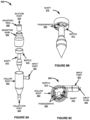
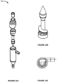
- FIG. 8A is an exploded-view diagram illustrating separator 800.
- Separator 800 is an example of separator 100, separator 202, separator 402, separator 422 and separator 602; however, separator 800 may include alternative configurations and methods of operation.
- separator 800 includes body 802, input port 804, suction port 806, collection port 808, baffle 810, vortex element 812, mounting base 846 and mounting ring 848.
- Body 802 includes a cylindrical wall defining a cylindrical cavity.
- the cylindrical wall includes a first cylindrical cavity end and a second cylindrical cavity end.
- Body 802 also forms a conical cavity.
- the conical cavity has a wide end and a narrow end. The wide end is mated to the second cylindrical cavity end of body 802.
- body 802 is configured to operate with the first cylindrical cavity end up.
- Body 802 is configured to allow gravity to pull at least liquid and solids separated from a flow of matter out collection port 808, while gasses separated from the flow of matter are pulled by suction out of suction port 806.
- Input port 804 is configured to receive a flow of matter. The flow of matter may be induced into separator 800 via suction port 806 by a suction or vacuum source. Input port 804 is configured to direct a flow of matter along the cylindrical cavity wall. By directing the flow of matter along the cylindrical cavity wall, liquids and gasses may cling to the wall of the cavity due to the effects of centripetal forces. Input port 804 is integral to body 802. Input port 804 is disposed in the cylindrical cavity wall of body 802. Input port 804 is located off-axis from an axis defined by the longitudinal center of the cylindrical cavity.
- Suction port 806 is configured to couple to suction source 816.
- suction source 816 may include a vacuum pump, aspirator, and/or a positive pressure operated suction source-such as suction sources that take advantage of Venturi or Coanda effect. Suction from suction source 816 creates suction at input port 804.
- Input port 804 is configured to receive a flow of matter. The flow of matter is pulled into input port 804 by the pressure difference between the ambient air pressure and the lower pressure provided by suction source 816. The flow of matter may include liquids, solids, and gasses, including combinations thereof in varying ratios.
- input port 804 may include fittings configured to attach tubing. For example, barbed or quick-disconnect type fittings may be used to couple tubing to input port 804.
- Collection port 808 is configured to expel a collection flow.
- the collection flow may comprise at least liquids and solids.
- Collection port 808 is disposed at the narrow end of the conical cavity of body 802.
- collection port 808 may be configured to couple to a collection canister.
- a collection canister may be used to measure the matter collected from separator 800.
- a collection canister may also be used for the safe collection and disposal of waste received from separator 800.
- collection port 808 may be coupled to tubing or piping to direct matter to a waste drain.
- collection port 808 may include mounting ring 848 configured to form a seal between collection port 808 to tubing or a collection canister.
- Baffle 810 is configured to prevent liquids or solids in the flow from being pulled directly from input port 804 to suction port 806 without traversing at least a first portion of a circumference of the cylindrical wall of separator body 802.
- Baffle 810 is disposed between input port 804 and suction port 806.
- Baffle 810 includes passageways configured to allow at least gasses in a flow of matter to separate from liquids and solids that maybe included in the flow. Gasses may be pulled through baffle 810 and out suction port 806.
- Baffle 810 includes a solid surface located proximal to input port 804 configured to direct the flow to traverse at least a first portion of a circumference of the cylindrical wall of body 802.
- the solid surface included in baffle 810 may to prevent liquids and solids in the flow from being pulled directly from input port 804 to suction port 806 by allowing time for gravity to act on the liquids and solids before they reach an opening in baffle 810. By allowing time for gravity to act on the liquids and solids as they traverse the solid surface of baffle 810, the liquids and solids can descend towards collection port 808 and thereby not be suctioned out of the suction port 806.
- Vortex element 812 is configured to allow a collection flow to pass through the annular cavity before dropping out collection port 808.
- the collection flow may comprise at least liquids and solids.
- Vortex element 812 includes a cylindrical central member disposed within the cylindrical cavity of body 802. The cylindrical central member forms an annular cavity between vortex element 812 and body 802.
- Vortex element 812 includes a tapered section disposed in the conical cavity of body 802.
- Vortex element 812 includes a plurality of cylindrical sections having different diameters.
- the plurality of cylindrical sections includes a first section that defines a first portion of the annular cavity and a second section that defines a second portion of the annular cavity.
- the tapered and cylindrical sections may be configured to direct the flow within body 802 in a cyclonic flow pattern.
- Baffle 810 is integral to vortex element 812.
- Mounting base 846 is configured to allow separator 800 to be assembled. Mounting base 846 is configured to couple to body 802. Mounting base 846 is configured to couple to mounting ring 848.
- Mounting ring 848 is configured to operate as a seal for suction port 806.
- Mounting ring 848 may be made from a flexible material that forms a seal between separator 800 and a coupling to a suction source.
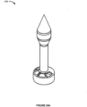
- FIG. 8B is a diagram illustrating vortex element 800.
- Vortex element 812 is configured to form an annular cavity between vortex element 812 and body 802.
- Vortex element 812 is configured to generate a vortex flow within body 802. The vortex flow and gravity may cause liquids and solids in a flow of matter received at input port 804 to separate from gasses.
- Vortex element 812 includes a cylindrical central member disposed within the generally cylindrical cavity of body 802.
- Vortex element 812 includes a tapered section disposed near the conical cavity of body 802.
- Vortex element 812 includes a plurality of cylindrical sections having different diameters. The plurality of cylindrical sections includes a first section that defines a first portion of the annular cavity and a second section that defines a second portion of the annular cavity.
- Baffle 810 is integral to vortex element 812.
- Vortex element 812 includes baffle 810.
- Baffle 810 is configured to prevent liquids or solids in the flow from being pulled directly from input port 804 to suction port 806 without traversing at least a first portion of a circumference of the cylindrical wall of separator body 802.
- Baffle 810 is disposed between input port 804 and suction port 806.
- Baffle 810 includes passageways configured to allow at least gasses in a flow of matter to separate from liquids and solids that maybe included in the flow. Gasses may be pulled through baffle 810 and out suction port 806.
- Baffle 810 includes a solid surface located proximal to input port 804 configured to direct the flow to traverse at least a first portion of a circumference of the cylindrical wall of body 802.
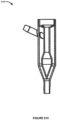
- FIG. 8D is a cross-section diagram illustrating the operation of separator 800.
- Separator 800 includes body 802, input port 804, suction port 806, collection port 808, baffle 810, vortex element 812, mounting base 846 and mounting ring 848. The elements in FIG. 8D have been previously described.
- a suction supply is coupled to suction port 806.
- Suction port 806 is configured to transfer suction from a suction source to input port 804.
- Suction from a suction source induces input flow 840 to enter input port 804.
- Baffle 810 includes passageways 850 configured to allow at least gasses included in input flow 840 to exit separator 800 via suction port 806.
- Baffle 810 includes a solid surface immediately proximal to input port 804 forcing input flow 840 to traverse at least a first portion of the interior of body 802.
- Vortex element 812 forms an annular opening between vortex element 812 and the interior cavity of body 802.
- a combination of cyclonic flow generated by separator 800 and gravity cause collection flow 844 to separate out of input flow 840.
- Collection flow 844 may include at least liquids and solids separated from input flow 840. Collection flow 844 is expelled out collection port 808. Separator 800 is configured to separate suction flow 842 from input flow 840. Suction flow 842 is pulled out suction port 806 by a suction source.
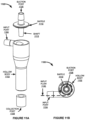
- separator 900 includes body 902, input port 904, suction port 906, collection port 908, baffle 910, vortex element 912, mounting base 946 and mounting ring 948.
- Mounting base 946 is configured to allow separator 900 to be assembled. Mounting base 946 is configured to couple to body 902. Mounting base 946 is configured to couple to mounting ring 948.
- Mounting ring 948 is configured to operate as a seal for suction port 906.
- Mounting ring 948 may be made from a flexible material that forms a seal between separator 900 and a coupling to a suction source.
- FIG. 9B is a diagram illustrating vortex element 912.
- Separator 900 includes vortex element 912.
- Vortex element 912 is configured to form an annular cavity between vortex element 912 and body 902.
- Vortex element 912 is configured to generate a vortex flow within body 902. The vortex flow and gravity may cause liquids and solids in a flow of matter received at input port 904 to separate from gasses. Liquids and gases may be expelled out collection port 908.
- Vortex element 912 includes a cylindrical central member disposed within the generally cylindrical cavity of body 902.
- Vortex element 912 includes a tapered section disposed near the conical cavity of body 902.
- Vortex element 912 includes a plurality of cylindrical sections having different diameters. The plurality of cylindrical sections includes a first section that defines a first portion of the annular cavity and a second section that defines a second portion of the annular cavity.
- Baffle 910 is integral to vortex element 912.
- Vortex element 912 includes baffle 910.
- Baffle 910 is configured to prevent liquids or solids in the flow from being pulled directly from input port 904 to suction port 906 without traversing at least a first portion of a circumference of the cylindrical wall of separator body 902.
- Baffle 910 is disposed between input port 904 and suction port 906.
- Baffle 910 includes passageways 950 configured to allow at least gasses in a flow of matter to separate from liquids and solids that maybe included in the flow. Gasses may be pulled through baffle 910 and out suction port 906.
- Baffle 910 includes a solid surface located proximal to input port 904 configured to direct the flow to traverse at least a first portion of a circumference of the cylindrical wall of body 902.
- baffle 910 may prevent liquids and solids in the flow from being pulled directly from input port 904 to suction port 906 by allowing time for gravity to act on the liquids and solids before they reach an opening in baffle 910. By allowing time for gravity to act on the liquids and solids as they traverse the solid surface of baffle 910, the liquids and solids can descend towards collection port 908 and thereby not be suctioned out of the suction port 906.
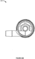
- FIG. 9C is a top-view diagram illustrating the operation of separator 900.
- a suction source coupled to suction port 906 induces input flow 940 within separator 900.
- Input flow 940 enters separator 900 through input port 904.
- Baffle 910 includes passageways 950 configured to allow at least gasses to exit separator 900 via suction port 906.
- Baffle 910 does not include passageways 950 immediately proximal to input port 904 forcing input flow 940 to traverse at least a first portion of a circumference of the interior of body 902.
- FIG. 9D is a cross-section diagram illustrating the operation of separator 900.
- Separator 900 includes body 902, input port 904, suction port 906, collection port 908, baffle 910, vortex element 912, mounting base 946 and mounting ring 948. The elements in FIG. 9D have been previously described.
- a suction supply is coupled to suction port 906.
- Suction port 906 is configured to transfer suction from a suction source to input port 904.
- Suction from a suction source induces input flow 940 to enter input port 904.
- Baffle 910 includes passageways 950 configured to allow at least gasses included in input flow 940 to exit separator 900 via suction port 906.
- Baffle 910 does not include passageways 950 immediately proximal to input port 904 forcing input flow 940 to traverse at least a first portion of the interior of body 902.
- Vortex element 912 forms an annular opening between vortex element 912 and the interior cavity of body 902.
- a combination of cyclonic flow generated by separator 900 and gravity cause collection flow 944 to separate out of input flow 940.
- Collection flow 944 may include at least liquids and solids separated from input flow 940. Collection flow 944 is expelled out collection port 908. Separator 900 is configured to separate suction flow 942 from input flow 940. Suction flow 942 is pulled out suction port 906 by a suction source.
- FIG. 10A is an exploded-view diagram illustrating separator 1000.
- Separator 1000 is an example of separator 100, separator 202, separator 402, separator 422 and separator 602; however, separator 1000 may include alternative configurations and methods of operation.
- separator 1000 includes body 1002, input port 1004, suction port 1006, collection port 1008, baffle 1010, vortex element 1012, mounting base 1046 and mounting ring 1048.
- Body 1002 includes a cylindrical wall defining a cylindrical cavity.
- the cylindrical wall includes a first cylindrical cavity end and a second cylindrical cavity end.
- Body 1002 also forms a conical cavity.
- the conical cavity has a wide end and a narrow end. The wide end is mated to the second cylindrical cavity end of body 1002.
- body 1002 is configured to operate with the first cylindrical cavity end up.
- Body 1002 is configured to allow gravity to pull at least liquid and solids separated from a flow of matter out collection port 1008, while gasses separated from the flow of matter are pulled by suction out of suction port 1006.
- a combination of cyclonic flow generated by separator 1100 and gravity may cause collection flow 1144 to separate from input flow 1140.
- Collection flow 1144 may include at least liquids and solids separated from input flow 1140.
- Collection flow 1144 is expelled out collection port 1108.
- Suction flow 1142 is pulled out suction port 1106 by a suction source.
- FIG. 12 is a block diagram illustrating a separator system 1200.
- Separator 1202 and separator 1222 are examples separator 100, separator 202, separator 402, separator 422 and separator 602, separator 800, separator 900, separator 1000, and separator 1100; however, separator system 1200 may include alternative configurations and methods of operation.
- suction source 1216 may include a vacuum pump, aspirator, and/or a positive pressure operated suction device that takes advantage of the Coanda effect.
- input port 1204 may include fittings configured to attach tubing. For example, barbed or quick-disconnect type fittings may be used to couple tubing to input port 1204.
- suction source 1216 supplies a suction flow to suction port 1226 via output tubing 1236.
- Separator 1222 is configured to transfer the suction flow to separator 1202.
- Suction flow 1242 creates a pressure near input port 1204 that is below the ambient air pressure. The ambient air pressure overcomes the pressure of the suction flow thereby inducing input flow 1240 into input port 1204.
- Input port 1204 is configured to receive input flow 1240.
- Input flow 1240 may comprise liquids, gasses and solids, including combinations thereof in varying ratios.
- Input flow 1240 may include surgical byproducts.
- Separator 1202 creates a cyclonic flow from the suction flow. The cyclonic flow and gravity cause a collection flow to separate from input flow 1240. The collection flow may comprise at least liquids and solids. The collection flow is expelled from collection port 1208.
- Collection port 1208 is configured to direct the collection flow to collection canister 1214.
- Separator 1202 separates a suction flow from a collection flow.
- the suction flow may comprise primarily gasses separated from input flow 1240.
- the suction flow is pulled from separator 1202 by suction source 1216.
- the suction flow is passed from suction port 1206 to input port 1224.
- Separator 1202 continues to operate in the first mode of operation until a fill volume within collection canister 1214 reaches a predetermined volume.
- Separators 1202, 1222 may be configured to pass input flow 1240 from input ports 1204, 1224 to suction ports 1206, 1226 unseparated when collection canisters 1214, 1234 reach predetermined fill volumes. In a second mode of operation, separator 1202 may pass input flow 1240 through suction port 1206 to separator 1222 unseparated.
- suction source 1216 supplies a suction flow from suction source 1216 to suction port 1226.
- Separator 1222 is configured to pass the suction flow to separator 1202. The suction flow pulls input flow 1240 into input port 1204. Separator 1202 passes input flow 1240 from input port 1204 to suction port 1206 unseparated because a predetermined fill volume within collection canister 1214 has been reached. Input flow 1240 is received by input port 1224. A fill volume in collection canister 1234 has not reached a predetermined fill volume.
- Separator 1222 separates a collection flow from a suction flow. The collection flow may comprise primarily liquids and solids from input flow 1240. Separator 1222 separates a suction flow from a collection flow. The collection flow is expelled out collection port 1228. Collection port 1228 is coupled to collection canister 1234. Collection canister 1234 is configured to receive a collection flow from collection port 1228. A suction flow is pulled out suction port 1226 by suction source 1216.
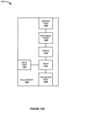
- FIG. 13A is a block diagram illustrating separator with filter 1300.
- Separator with filter 1300 is an example of separator 100, separator 202, separator 402 and separator 602; however, separator with filter 1300 includes electric filter 1352.
- separator with filter 1300 may include alternative configurations and methods of operation than the previously described embodiments.
- Separator with filter 1300 includes separator body 1302, input port 1304, suction port 1306, collection port 1308, baffle 1310, vortex element 1312 and electric filter 1352 and filter controller 1354.
- separator 1300 is configured to separate liquids, solids and gasses in a flow of matter. Separator 1300 ejects liquids and solids separated from the flow of matter out collection port 1308 while suctioning at least gasses separated from the flow of matter out suction port 1306. Separator 1300 is operated by suction received from a suction source. Separator with filter 1300 is further configured to filter particles from gasses suction from suction port 1306.
- Separator with filter 1300 includes separator body 1302.
- Separator body 1302 includes a cylindrical wall defining a cylindrical cavity.
- the cylindrical wall includes a first cylindrical cavity end and a second cylindrical cavity end.
- Separator body 1302 also forms a conical cavity.
- the conical cavity has a wide end and a narrow end. The wide end is mated to the second cylindrical cavity end of separator body 1302.
- separator body 1302 is configured to operate with the first cylindrical cavity end up.
- Separator body 1302 is configured to allow gravity to pull at least liquid and solids separated from a flow of matter out collection port 1308, while gasses separated from the flow of matter are pulled by suction out of suction port 1306.
- Separator with filter 1300 includes input port 1304.
- Input port 1304 is configured to receive a flow of matter.
- input port 1304 may be integral to separator body 1302.
- Input port 1304 may be disposed in the cylindrical cavity wall.
- Input port 1304 may be located off-axis from an axis defined by the longitudinal center of the cylindrical cavity.
- Input port 1304 may be configured to direct a flow of matter along the cylindrical cavity wall. By directing the flow of matter along the cylindrical cavity wall, liquids and gasses may cling to the wall of the cavity due to the effects of centripetal forces.
- the flow of matter may be induced into separator 1300 by suction received from suction port 1306 by a suction or vacuum source.
- Suction port 1306 is configured to couple to a suction source.
- the suction source may include a vacuum pump, aspirator, and/or a positive pressure operated suction source-such as suction sources that take advantage of Venturi or Coanda effect.
- Suction from a suction source is transferred from suction port 1306 to input port 1304.
- Input port 1304 is configured to receive a flow of matter. The flow of matter is pulled into input port 1304 by the pressure difference between the ambient air pressure the lower pressure provided by the suction source.
- the flow of matter may include liquids, solids, and gasses, including combinations thereof in varying ratios.
- Suction port 1306 is disposed near the first cylindrical cavity end.
- Suction port 1306 provides suction received from a suction source for operating separator canister with filter 1300.
- suction port 1306 may include fittings configured to attach tubing.
- barbed or quick-disconnect type fittings may be used to couple tubing to suction port 1306.
- the tubing may be used to couple suction port 1306 to a suction source or to an input port 1304 of another separator system.
- baffle 1310 may be used to prevent liquids and solids in the flow from being pulled directly from input port 1304 to suction port 1306 by allowing time for gravity to act on the liquids and solids before they reach an opening in baffle 1310. By allowing time for gravity to act on the liquids and solids as they traverse the solid surface of baffle 1310, the liquids and solids can descend towards collection port 1308 and thereby not be suctioned out of the suction port 1306.
- Vortex element 1312 is configured to direct a flow of matter in a cyclonic flow. The cyclonic flow and gravity may cause liquids, solids and gasses included in the flow of matter to separate.
- Vortex element 1312 includes a cylindrical central member disposed within the cylindrical cavity of separator body 1302. The cylindrical central member forms an annular cavity between vortex element 1312 and separator body 1302. Vortex element 1312 is configured to allow liquids and solids in the flow to pass through the annular cavity before dropping out collection port 1308.
- vortex element 1312 may include a tapered section disposed in the conical cavity of separator body 1302.
- vortex element 1312 may include a plurality of cylindrical sections having different diameters.
- the plurality of cylindrical sections may include a first section that defines a first portion of the annular cavity and a second section that defines a second portion of the annular cavity.
- the tapered and cylindrical sections may be configured to direct the flow within separator body 1302 in a cyclonic flow pattern.
- baffle 1310 may be integral to vortex element 1312.
- Electric filter 1352 is configured to use electrical charge to capture particles that may be included in a flow exiting suction port 1306.
- Electric filter 1352 may comprise a matrix of conductive elements.
- the conductive elements may be iron, steel, copper or some other conductive element.
- the matrix may be comprised of stacked screens.
- the matrix may be comprised of entwined wire.
- Electric filter 13552 is coupled to filter controller 1354.
- Electric filter 1352 is configured to receive power from filter controller 1354.
- Filter controller 1354 is configured to operate electric filter 1352 in such a manner as to collect particles included in a flow of matter using an electrical charge.
- Filter controller 1354 is configured to provide electric filter 1352 power at a particular voltage level, current level and possibly frequency.
- filter controller 1354 may be configured to provide direct current.
- filter controller may include a microcontroller configured to power electric filter 1352.
- FIG. 13B is a block diagram illustrating separator with filter 1300.
- separator with filter 1300 includes biological filter 1356 rather than electric filter 1352.
- Biological filter 1356 is configured to trap biological elements possibly included in a flow to be expelled from suction port 1306.
- Various embodiments of filter 1352 may be configured to trap specific types of biological elements using different operations.
- Biological filter 1356 is disposed within separator body 1302.
- Biological filter 1356 includes one or more filter inlet ports and one or more filter output ports.
- the one or more filter inlet ports are configured to receive a flow of matter from baffle 1310.
- Elements comprising biological filter 1356 are configured to trap biological elements possibly contained in the flow of matter and passes a filtrate to suction port 1306.
- Biological filter 1356 may comprise mechanical, biological, chemical or other types of filters including any combination thereof to trap biological elements.
- Mechanical filtration may include physical barrier or filter media type filters including combinations thereof.
- Filters using a physical barrier or filter media retain biological elements by physically blocking the biological elements from passing through the filter media.
- Filter media mechanically or physically strains biological elements from the effluent passing through it.
- Filter media is available in a variety of materials and porosities, which may be selected to limit the size of biological elements they can extract. Combinations of different materials and porosities of filter media may be used to separate specific elements comprising an effluent of the collected matter and the gasses received via input port 11304 out suction port 1306.
- Input port 1604 is configured to receive a flow of matter.
- input port 1604 may be integral to separator body 1602.
- Input port 1604 may be disposed in the cylindrical cavity wall.
- Input port 1604 may be located off-axis from an axis defined by the longitudinal center of the cylindrical cavity.
- Input port 1604 may be configured to direct a flow of matter along the cylindrical cavity wall. By directing the flow of matter along the cylindrical cavity wall, liquids and gasses may cling to the wall of the cavity due to the effects of centripetal forces.
- the flow of matter may be induced into separator 1600 by suction received from suction port 1606 by a suction or vacuum source.
- Tissue trap 1762 is configured to trap solids that may be included in a combined flow expelled from collection port 1706. Liquids included in the combined flow are allowed to pass through tissue trap 1762 to collection canister 1714. The solids may include tissue, blood clots, foreign objects or other solid forms of matter. Tissue trap 1762 includes a means for mechanical filtration of solids that may be included in a combined flow expelled from collection port 1706. Solids collected by tissue trap 1762 may be saved for analysis or safely disposed of.
- Separator body 1802 includes a cylindrical wall defining a cylindrical cavity.
- the cylindrical wall includes a first cylindrical cavity end and a second cylindrical cavity end.
- Separator body 1802 also forms a conical cavity.
- the conical cavity has a wide end and a narrow end. The wide end is mated to the second cylindrical cavity end of separator body 1802.
- separator body 1802 is configured to operate with the first cylindrical cavity end up.
- Separator body 102 is configured to allow gravity to pull at least liquid and solids separated from a flow of matter out collection port 1808, while gasses separated from the flow of matter are pulled by suction out of suction port 1806.
- Input port 1804 is configured to receive a flow of matter.
- input port 1804 may be integral to separator body 1802.
- Input port 1804 may be disposed in the cylindrical cavity wall.
- Input port 1804 may be located off-axis from an axis defined by the longitudinal center of the cylindrical cavity.
- Input port 1804 may be configured to direct a flow of matter along the cylindrical cavity wall. By directing the flow of matter along the cylindrical cavity wall, liquids and gasses may cling to the wall of the cavity due to the effects of centripetal forces.
- the flow of matter may be induced into separator with check valve 1800 by suction received from suction port 1806 by a suction or vacuum source.
- Collection port 1808 is configured to expel at least liquids and solids. Collection port 1808 is disposed near the narrow end of the conical cavity of separator body 1802. In an embodiment, collection port 1808 may be configured to couple to a collection canister. A collection canister may be used to measure the matter collected from separator with check valve 1800. A collection canister may also be used for the safe collection, transportation and disposal of waste received from separator with check valve 1800. In some embodiments, collection port 1808 may be coupled to tubing or piping to direct matter to a waste drain. In some embodiments, collection port 1808 may include a mounting ring configured to form a seal between collection port 1808 to tubing or a collection canister.
- the flow of matter may comprise a gas, a liquid, a solid, or any combination thereof.
- the flow of matter may comprise one or more gases.
- the flow of matter may comprise one or more liquids.
- the flow of matter may comprise one or more solids.
- the flow of matter may comprise biological material, such as blood, extracellular fluid, lymph fluid, urine, bile, semen, fecal matter, sweat, cells, cell fragments, tissues, tissue fragments or particulates, amniotic fluid, aqueous humour, vitreous humour, bile, breast milk, cerebrospinal fluid, chyle, exudates, gastric juice, pericardial fluid, peritoneal fluid, pleural fluid, pus, rheum, saliva, sebum, serous fluid, sputum, synovial fluid, tears, vomit, or others.
- the flow of matter may comprise a salt solution, saline, an electrolyte-based fluid, sugar-containing fluids, or carbon dioxide gas.
- the flow of matter may comprise surgical waste, such as lavage fluids.
- the flow of matter may comprise gases, liquids, or solids generated from a surgical procedure.
- One or more components of the system are disposable.
- One or more surgical instruments, one or more flow separation devices, one or more canisters, or any combination thereof is disposable.
- a surgical instrument is disposable.
- a flow separation device is disposable.
- a canister is disposable.
- One or more components of the system are suitable for more than a single use.
- One or more surgical instruments, one or more flow separation devices, one or more canisters, or any combination thereof is suitable for more than a single use.
- a surgical instrument is suitable for more than a single use.
- a flow separation device is suitable for more than a single use.
- a canister is suitable for more than a single use.
- One or more components of the system are sterilized.
- One or more surgical instruments, one or more flow separation devices, one or more canisters, or any combination thereof is sterilized.
- a surgical instrument is sterilized.
- a flow separation device is sterilized.
- a canister is sterilized.
- Suction attachment 1946 is used by a surgeon to suction material from a surgical field which includes, for example, blood, fat, pus, irrigation fluid, bone, surgical smoke, and other similar organic and inorganic materials.
- Materials suctioned from the surgical field are transmitted to the separator 1902 through input tubing 1930.
- the material suctioned through the surgical suction instrument is separated in the separator 1902 so that a gas (e.g. surgical smoke) is drawn out through the top of the separator 1902 and any liquid and/or solid material is drawn by gravity (and/or suction) into the canister 1914.
- a gas e.g. surgical smoke
- any liquid and/or solid material is drawn by gravity (and/or suction) into the canister 1914.
- surgical system 1900 may also be configured for use with two or more separators either in series or in parallel as described herein.
- a system may comprise a surgical instrument, a suction source, and one or more separators.
- the one or more separators may be operatively connected in series, such as connected via tubing.
- the system may also comprise collection canisters attachable to each of the one or more separators.
- at least one of the one or more separators comprises a canister formed therein.
- a system comprising one or more separators in series may permit filling a volume of a first canister in the series with a liquid of the flow of matter followed by filling a volume of a second canister in the series with a liquid of the flow of matter followed by filling a volume of a third canister in the series and so on.
- a system of separators in series may permit the collection of liquids from a flow of matter into a series of canisters and separation of gas from the flow of matter during continuous suction use of the surgical instrument.
- a system of separators in series permits continuous suction use of the surgical instrument with a greater liquid collection volume compared to a single separator.
- a flow separation device i.e. a separator
- a flow separation device is operatively coupled to a canister.
- a flow separation device is retrofitted to an existing canister.
- a flow separation device is integrated into a canister.
- a flow separation device is operatively coupled to a smoke filtration canister. In some embodiments, a flow separation device is operatively coupled to a smoke filtration canister via a port, such as a suction port. In some embodiments, a flow separation device is in fluid communication with a smoke filtration canister via a tubing. In some embodiments, a flow separation device is attachable to a smoke filtration canister. In some embodiments, a flow separation device is retrofitted to an existing smoke filtration canister. In some embodiments, a flow separation device is formed therein a smoke filtration canister. In some embodiments, a flow separation device is integrated into a smoke filtration canister. In some embodiments, a flow separation device is an accessory, such as an optional accessory, to a smoke filtration canister.
- a flow of matter enters the flow separation device from the surgical instrument at the input port.
- the flow of matter may comprise a gas, a liquid, a solid, or any combination thereof.
- the flow separation device enhances the suction capacity of the surgical instrument compared to a surgical instrument without a flow separation device operatively coupled.
- the flow separation device enhances the suction capacity of a suction source, such as a passive suction source, compared to a system without a flow separation device operatively coupled.
- the flow separation device is configured to separate the gas, the liquid, the solid, or any combination thereof.
- the gas exits the flow separation device from a different port that the liquid exits. For example, the gas exits the suction port and the fluid exits the collection port.
- a liquid exiting the collection port of the flow separation device is collected in a canister, such as a collection canister, that is operatively coupled to the flow separation device.
- the solid is collected in one or more filters of the flow separation device. In some embodiments, the solid also exits the collection port with the liquid.
- the system may include one or more valves, such as a shut off valve, a ball valve, a butterfly valve, a clapper valve, a check valve, a choke valve, a diaphragm valve, a gate valve, a pinch valve, a piston valve, a plug valve, a poppet valve, a safety valve, or any combination thereof.
- the one or more valves is operatively coupled to the flow separation device, the surgical instrument, the suction source, or any combination thereof.
- One or more valves are included as a safety feature of the system.
- One or more valves are included to optimize performance of the system.
- a shut off valve may shut off the system if a volume of liquid within the flow separation device exceeds a specified volume, such as a volume greater than 70%, 75%, 80%, 85%, 90%, 95%, 96%, 97%, 98%, 99% or greater the total inner volume of the hollow body of the flow separation device.
- a shut off valve may shut off the system if a volume of liquid within the flow separation device exceeds a volume greater than 70% the total inner volume of the hollow body of the flow separation device.
- a shut off valve may shut off the system if a volume of liquid within the flow separation device exceeds a volume greater than 80% the total inner volume of the hollow body of the flow separation device.
- a shut off valve may shut off the system if a volume of liquid within the flow separation device causes the liquid to begin to exit all ports of the flow separation device.
- FIG. 21A, 21B , and 21C show an embodiment of the separator wherein the input port of the separator at an angle relative to a central axis of the hollow body that is less than 90 degrees.
- the input port is angled relative to the central axis at about 85°, 80°, 75°, 70°, 65°, 60°, 55°, 50°, 45°, 40°, 35°, 30°, 25°, 20° or less.
- the input port is angled at about 70° or less.
- he input port is angled at about 60° or less.
- the input port is angled at about 50° or less.
- the input port is angled at about 40° or less.
- the input port is angled at about 30° or less. In some embodiments, the input port is angled from about 20° to about 50°. In some embodiments, the input port is angled from about 40° to about 70°. In some embodiments, the input port of the separator is angled to enhance entry of the flow of matter into the input port, enhance a cyclonic pattern of flow along an inner surface of the hollow body, or enhance movement of liquid towards the collection port, or any combination thereof. In some embodiments, the cyclonic pattern of flow along an inner surface of the hollow body may aid in separation of a gas from a liquid of the flow of matter. In some embodiments, the input port of the separator is configured to direct a flow entering the separator against the wall of the separator as the flow enters the separator.
- FIG. 21D shows a bottom view of an embodiment wherein an input port opening enters the separator and contacts the central column (or shaft) of the separator.
- an input port opening typically fluid traveling from a smaller diameter conduit into a larger diameter conduit tends to expand at the point of intersection of the smaller conduit with the larger conduit.
- the opening of the input port enters into the larger diameter interior of the separator so that fluid expansion is decreased (as compared to, for example, an input port that opens directly into a larger conduit).
- the opening of the input port is shaped so that a side of the input port opening extends and contacts the central column (or shaft) while the opening gradually curves away from that point so that the edge of the opening tapers away from the point at which the opening of the input port contacts the central column.
- This configuration directs flow of liquid and/solid suction material against the inner surface of the separator while the contact of the input port with the column tends to draw the flow of gaseous components in the suction flow around the central column due to a Coanda effect.
- the initial separation of the gas and fluid due to the shape and positon of the input port as shown in FIG. 21D enhances the separation as described herein.
- FIG. 22A and 22B show a side view and bottom view respectively of an input port opening into a separator wherein the opening contacts the central column (or shaft).
- the opening of the input port is essentially flat without any taper. Similar to the embodiment shown in FIG. 21D , a gaseous component of a suction flow will tend to be drawn to around the central column of the separator when the suction flow enters the separator due to the Coanda effect. Because the opening of the input port opens into the separator, as in FIG. 21D , there will be a decrease or prevention of expansion of the suction flow as it leaves the input port.
- a baffle comprises a solid surface that is proximal to the opening of the input port.
- openings in the baffle do not extend around the entire circumference of the baffle.
- the solid surface of the baffle and its position immediately proximal to the opening of the input port blocks liquids and or/solids entering the separator so that the liquids and/or solids are not immediately drawn up and out of the suction port of the separator. Rather blocking the initial escape of solid and/or liquid components of the suction flow by the solid portion of the baffle allows for gravity (and/or suction from the direction of the canister) to draw the liquids and/or solids down towards the bottom of the separator.
- the gaseous components of the mixture are also initially blocked by the solid component of the baffle but these components are affected more strongly by the suction force through the suction port (i.e. more strongly than gravity and/or a suction force from the direction of the canister) which draws the gaseous components up and out of the separator through the holes in the baffle which are positioned past the solid portion of the baffle.
- baffles with a solid portion near an input port may be used with any and all devices, systems, and methods described herein.
- the separator comprises one or more baffles.
- the one or more baffles may individually comprise a plurality of openings.
- the plurality of openings may comprise 3, 4, 5, 6, 7, 8, 9, 10, or more openings.
- the plurality of openings is 3.
- the plurality of openings is 4.
- the plurality of openings is 5.
- the plurality of openings is 6.
- the plurality of openings is 7.
- the plurality of openings is 8.
- the plurality of openings is 9.
- the plurality of openings is 10.
- the plurality of openings is positioned on the one or more baffles such that they are distal to the input port.
- the one or more baffles is positioned on a first end of the shaft that is adjacent a second conical end. In some embodiments, the one or more baffles are configured to receive at least a portion of the flow of matter to pass through the one or more openings. In some embodiments, the one or more baffles are configured to aid in the separation of gas from liquid of the flow of matter entering the separator.
- FIG. 23A-23D show different views of a baffle coupled with helical surface.
- a baffle may be shaped or coupled with a helix.
- the helix is configured to guide the flow of the liquid and/or solid components within the suction flow along a helical track down towards the bottom (i.e. the exit port) of the separator.
- a helical baffle may be right-handed or left-handed.
- the helical baffle may be a conical helix, a circular helix, a cylindrical helix, or other.
- a helical baffle may form a single complete rotation about the shaft.
- a helical baffle may form a single complete rotation about the hollow body.
- a helical baffle may form more than one complete rotation about the shaft.
- a helical baffle may form rotations along a portion of the shaft.
- a helical baffle may form rotations along a portion of the hollow body.
- a helical baffle may form rotations about a shaft or the hollow body along a portion of the shaft or hollow body between the suction port and the input port.
- the shaft may comprise one or more helical structures, such as indentations or protrusions.
- a helical structure may be right-handed or left-handed.
- the helical structure may be a conic helix, a circular helix, a cylindrical helix, or other.
- a helical structure may form a single complete rotation about the shaft.
- a helical structure may form more than one complete rotation about the shaft.
- a helical structure may form rotations along a portion of the shaft.
- a helical structure may form rotations about a shaft along a portion of the shaft between the suction port and the input port.
- a helical structure may form rotations about a shaft along a portion of the shaft between the input port and the collection port.
- a helical structure may form rotations about a shaft along the entire length of the shaft.
- a shaft may comprise one or more openings.
- An opening in a shaft may permit one or more gases to exit the hollow body, such as via the hollow lumen of the shaft towards the suction port.
- An opening on the shaft may be a circumferential gap space, such as an annular opening.
- An opening on the shaft may be positioned distal to the input port.
- An opening on the shaft may be positioned on a portion of the bulbous end.
- the initial angle may be about 5 degrees, 10 degrees, 15 degrees, 20 degrees, 25 degrees, 30 degrees, 35 degrees, 40 degrees, 45 degrees, 50 degrees, 55 degrees, 60 degrees, 65 degrees, 70 degrees, 75 degrees, or 80 degrees relative a central axis of the shaft.
- the initial angle may be about 25 degrees relative a central vertical axis of the shaft.
- the initial angle may be about 30 degrees relative a central vertical axis of the shaft.
- the initial angle may be about 35 degrees relative a central vertical axis of the shaft.
- the initial angle may be about 40 degrees relative a central vertical axis of the shaft.
- the initial angle may be about 40 degrees relative a central vertical axis of the shaft.
- One or more baffles may be attachable thereto the shaft.
- the one or more baffles may be formed therein the shaft.
- a baffle may be positioned along the shaft at a location that is distal to the collection port and adjacent to a suction port.
- a baffle may be positioned along the shaft at a location that is distal to the collection port and between the suction port and the input port.
- a baffle may prevent liquids entering the hollow body via the input port from exiting the suction port.
- a baffle may be a physical barrier to prevent liquids entering the hollow body via the input port from exiting the suction port.
- a baffle may direct liquids entering the hollow body via the input port to flow towards a collection port.
- Table 1 is a chart illustrating test results of a separator.
- the chart illustrates data relating to two different types of suction devices with and without a separator in use.
- the first type of suction device listed in the chart is a Yankauer suction tip.
- a Yankauer suction tip is an oral suctioning tool typically comprised of a firm plastic suction tip with a large opening surrounded by a bulbous head and is designed to allow effective suction without damaging surrounding tissues.
- the second type of suction device (FIRST) listed in the chart is a suction device designed for use in various surgical procedures and may include ports that is variably opened and closed to adjust a ratio of liquids, solids and gasses suctioned by the FIRST device.
- SLS refers to the separator disclosed herein.
- the test setup included four collection canisters coupled in series, as is used in a common operating room setup.
- FIG. 12 illustrates an example of two collection canisters 1214, 1234 including two separators 1202, 1222 coupled in series.
- the canisters were coupled to a CONMED ® System 1200TM Smoke Evacuation System (SES).
- SES Smoke Evacuation System
- the chart illustrates the time taken to suction 500 cc of 35% glycerol solution at room temperature.
- the chart illustrates data pertaining to the suction strength of the two suction devices.
- the Yankauer device provided strong suction with and without a separator in use.
- suction time decreased from 18 seconds to 11 seconds with the use of a separator system, such as the separator examples described herein.
- the FIRST device was able to suction 500 cc of 35% glycerol in 133 seconds without the use of a separator. Adding one separator to the system decreased the suction time to 70 seconds. Performance of the FIRST device was improved even further by adding a second separator to the system.
- the suction time of the FIRST device in conjunction with two separators decreased to 50 seconds.
- the data shows that the use of a separator, the examples as described herein, may reduce the suction time of various suction times by nearly one-half.
- a flow separation device comprising:
- Item 2 The separator of item 1, wherein the input port is located off-axis of an axis defined by the longitudinal center of the separator body.
- Item 3 The separator of item 1, wherein the input port is located closer to the first cylindrical end than the second cylindrical end.
- Item 4 The separator of item 1, wherein the suction source comprises a vacuum pump.
- Item 5 The separator of item 1, wherein the suction source comprises a positive pressure operated suction generator that utilizes a Coanda effect.
- Item 6 The separator of item 1, wherein the suction source comprises a positive pressure operated suction generator that utilizes a Venturi effect.
- Item 7 The separator of item 1, wherein the baffle comprises a plurality of openings to allow passage of the flow of matter, comprising separated portions thereof, out of the suction port.
- Item 8 The separator of item 7, wherein the baffle comprises a solid surface located proximal to the input port and distal to the plurality of openings, configured to prevent the flow of matter, comprising separated portions thereof, from passing directly from the input port to the suction port without first traversing at least a portion of a circumference of the cylindrical cavity wall.
- Item 9 The separator of item 1, wherein the baffle is integral to the cylindrical shaft.
- Item 10 The separator of item 1, wherein the cylindrical shat comprises a plurality of conic sections each comprising a wide end and a narrow end of varying diameters and a plurality of cylindrical sections of varying diameter configured to direct the flow of matter within the cylindrical cavity.
- Item 11 The separator of item 1, further configured to allow passage of the flow of matter, unseparated, from the input port to the suction port when the flow of matter is no longer able to be expelled out of the collection port.
- Item 12 A method of operating a separator comprising: providing a separator comprising:
- Item 13 The method of operating a separator of item 12, further comprising locating the input port off-axis of an axis defined by a longitudinal center of the separator body.
- Item 14 The method of operating a separator of item 12, further comprising locating the input port closer to the first cylindrical end than the second cylindrical end.
- Item 15 The method of operating a separator of item 12, further comprising providing the suction source using a vacuum pump.
- Item 16 The method of operating a separator of item 12, further comprising providing the suction source using a positive pressure operated suction generator that utilizes a Coanda effect.
- Item 17 The method of operating a separator of item 12, further comprising providing the suction source using a positive pressure operated suction generator that utilizes a Venturi effect.
- Item 18 The method of operating a separator of item 12, further comprising providing the baffle with a plurality of openings allowing passage of the flow of matter, comprising separated portions thereof, out of the suction port.
- Item 19 The method of operating a separator of item 18, further comprising providing the baffle a solid surface located proximal to the input port and distal to the opening, thereby preventing the flow of matter, comprising separated portions thereof, from passing directly from the input port to the suction port without first traversing at least a portion of a circumference of the cylindrical cavity wall.
- Item 20 The method of operating a separator of item 12, further comprising integrating the baffle to the cylindrical shaft.
- Item 21 The method of operating a separator of item 12, further comprising providing the cylindrical shaft a plurality of conic sections each comprising a wide end and a narrow end of varying diameters and a plurality of cylindrical sections of varying diameter thereby directing the flow of matter along the cylindrical cavity wall.
- Item 22 The method of operating a separator of item 12, further comprising allowing passage of the flow of matter, unseparated, from the input port to the suction port when the flow of matter is no longer expelling out of the collection port.
- Item 23 The method of operating a separator of item 12, further comprising providing the suction source using a vacuum pump.
- Item 24 The method of operating a separator of item 12, further comprising providing the suction source using a positive pressure operated suction device that utilizes a Coanda effect.
- Item 25 The method of operating a separator of item 12, further comprising coupling the separator to a canister.
- Item 26 A system of flow separators comprising: one or more separators, each comprising:
- Item 27 The separator system of item 26, wherein the suction port of one separator is coupled to the input port of another separator.
- Item 28 The separator system of item 26, wherein the one or more separators are configured to discontinue filling a first canister when the first canister has reached a pre-determined volume and allow the flow of matter, unseparated, to pass through the input port and out of the output port of a first separator to the input port of a second separator coupled to a canister that is not filled to a pre-determined capacity.
- Item 29 A method of operating a separator system comprising: providing one or more separators, each comprising:
- Item 30 The method of operating a series of separators of item 29, further comprising providing the suction source using a vacuum pump.
- Item 31 The method of operating a series of separators of item 29, further comprising providing the suction source using a positive pressure operated suction generator that utilizes a Coanda effect.
- a liquid-gas flow separator comprising:
- Item 33 The separator of item 32, wherein the flow of matter further comprises solids, the solids in the flow of matter pass through the annular cavity before dropping out the collection port.
- Item 34 The separator of item 32, wherein the baffle comprises a plurality of openings to allow the gasses in the flow of matter to be pulled out of the separator via the suction port.
- Item 35 The separator of item 34, wherein the baffle comprises a solid portion that prevents liquids in the flow of matter from being pulled directly from the input port to the suction port, the solid portion corresponding to at least the first portion of the circumference.
- Item 36 The separator of item 32, wherein the central member comprises a tapered section disposed in the conical cavity.
- Item 37 The separator of item 32, wherein the central member comprises a plurality of cylindrical sections comprising different diameters.
- Item 38 The separator of item 37, wherein a plurality of cylindrical sections include a first section that defines a first portion of the annular cavity and a second section that defines a second portion of the annular cavity.
- Item 39 The separator of item 38, wherein the first portion is disposed between the baffle and the second portion, the second portion is disposed between the first portion and the conical cavity.
- Item 40 The separator of item 39, wherein the central member further comprises a tapered section disposed in the conical cavity thereby forming a hollow cone shaped cavity, the hollow cone shaped cavity disposed between the second portion and the second port.
- Item 41 A method of operating a liquid-gas flow separator, comprising:
- Item 42 The method of operating a separator of item 41, further comprising providing a flow further comprising solids and passing the solids in the flow through the annular cavity before dropping out the collection port.
- Item 44 The method of operating a separator of item 41, further comprising preventing liquids in the flow from being pulled directly from the input port to the suction port by providing the baffle comprising a solid portion, the solid portion corresponding to at least the first portion of the circumference.
- Item 46 The method of operating a separator of item 41, further comprising providing the central member comprising a plurality of cylindrical sections comprising different diameters.
- Item 47 The method of operating a separator of item 41, further comprising providing a plurality of cylindrical sections comprising a first section defining a first portion of the annular cavity and a second section defining a second portion of the annular cavity.
- Item 48 The method of operating a separator of item 47, further comprising disposing the first portion between the baffle and the second portion and disposing the second portion between the first portion and the conical cavity.
- Item 49 The method of operating a separator of item 48, further comprising providing the central member a tapered section disposed in the conical cavity thereby forming a hollow cone shaped cavity and disposing the hollow cone shaped cavity between the second portion and the collection port.
- a flow separator comprising:
- Item 54 The separator of item 50, wherein the central member comprises a tapered section disposed in the conical cavity, and means for directing the flow of matter within the separator.
- Item 55 The separator of item 50, wherein the central member comprises a plurality of cylindrical sections comprising different diameters, and means for directing the flow of matter within the separator.
- Item 56 The separator of item 55, wherein a plurality of cylindrical sections include a first section that defines a first portion of the annular cavity and a second section that defines a second portion of the annular cavity, and means for directing the flow of matter within the separator.
- Item 57 The separator of item 56, wherein the first portion is disposed between the baffle and the second portion, the second portion is disposed between the first portion and the conical cavity, and means for directing the flow of matter within the separator.
- Item 58 The separator of item 57, wherein the central member further comprises a tapered section disposed in the conical cavity thereby forming a hollow cone shaped cavity, the hollow cone shaped cavity disposed between the second portion and the collection port, and means for directing the flow of matter through the hollow cone shaped cavity.
- Item 59 A system of liquid-gas separators comprising:
- Item 60 The system of item 59, wherein the flow of matter comprises one or more of liquids, solids and gasses, and means for the liquids and/or solids to pass through the annular cavity and out of the collection port.
- Item 62 The system of item 61, wherein the baffle comprises a solid portion disposed proximally to the input port, and means for preventing liquids and/or solids in the flow from being pulled directly from the input port to the suction port before traversing at least a portion of the circumference of the cylindrical cavity wall.
- Item 63 The system of item 59, wherein the central member comprises a tapered section disposed in the conical cavity, and means for directing the flow of matter within the separator.
- Item 64 The system of item 59, wherein the central member comprises a plurality of cylindrical sections comprising different diameters, and means for directing the flow of matter within the separator.
- Item 65 The system of item 64, wherein a plurality of cylindrical sections include a first section that defines a first portion of the annular cavity and a second section that defines a second portion of the annular cavity, and means for directing the flow of matter within the separator.
- Item 66 The system of item 65, wherein the first portion is disposed between the baffle and the second portion, the second portion is disposed between the first portion and the conical cavity, and means for directing the flow of matter within the separator.
- Item 67 The system of item 66, wherein the central member further comprises a tapered section disposed in the conical cavity thereby forming a hollow cone shaped cavity, the hollow cone shaped cavity disposed between the second portion and the second port, and means for directing the flow of matter through the hollow cone shaped cavity.
- Item 68 The system of item 59, wherein the suction port of a first separator is coupled to the input port of a second separator, and means for providing suction to the first separator through the second separator.
- Item 69 The system of item 68, further comprising a means for allowing the flow of matter to pass from the input port to the suction port of the first separator, when the canister corresponding to the first separator is filled to a capacity, to the second separator and collecting at least a portion of the flow of matter in the canister corresponding to the second separator.
- Item 70 The system of item 59, wherein the suction source comprises a vacuum pump, and means for providing vacuum to the suction port.
- Item 71 The system of item 59, wherein the suction source comprises a means for generating suction based on a Coanda effect.
- Item 72 The system of item 59, wherein the suction source comprises a means for generating suction based on a Venturi effect.
- Item 73 A separator for use in a medical environment, comprising:
- Item 74 The separator of item 73, wherein the flow further comprises solids, the solids in the flow to pass through the annular cavity before dropping out the second port.
- Item 75 The separator of item 73, wherein the liquids include intracellular fluids and extracellular fluids.
- Item 76 The separator of item 73, wherein the liquids include blood.
- Item 77 The separator of item 73, wherein the gas comprises smoke generated from electrosurgical tools comprising a bovie, harmonic scalpel, electrosurgical pencil and laser.
- Item 78 The separator of item 73, wherein the baffle comprises a plurality of openings to allow the gasses in the flow be pulled out of the separator via the first port.
- Item 79 The separator of item 75, wherein the baffle comprises a solid portion that prevents liquids in the flow from being pulled directly from the collection port to the first port, the solid portion corresponding to at least the first portion of the circumference.
- Item 80 The separator of item 73, wherein the central member comprises a tapered section disposed in the conical cavity.
- Item 81 The separator of item 73, wherein the central member comprises a plurality of cylindrical sections comprising different diameters.
- Item 82 The separator of item 81, wherein a plurality of cylindrical sections include a first section that defines a first portion of the annular cavity and a second section that defines a second portion of the annular cavity.
- Item 83 The separator of item 82, wherein the first portion is disposed between the baffle and the second portion, the second portion is disposed between the first portion and the conical cavity.
- Item 84 The separator of item 83, wherein the central member further comprises a tapered section disposed in the conical cavity thereby forming a hollow cone shaped cavity, the hollow cone shaped cavity disposed between the second portion and the second port.
- Item 85 A method of operating a separator in a medical environment, comprising:
- Item 93 A system for separating a flow of matter comprising:
- Item 96 The system of item 93, wherein the one or more baffles are configured to prevent the flow of matter from passing directly from the input port to the suction port without first traversing at least a portion of a circumference of an inner surface of the hollow body.
- Item 98 The system of item 97, wherein the plurality of openings are distal to the input port.
- Item 101 The system of item 93, wherein the hollow body comprises a cylindrical shape.
- Item 103 The system of item 93, wherein the flow of matter comprises biological material.
- Item 104 The system of item 93, wherein the input port is proximal to the suction port and distal from the collection port.
- Item 105 The system of item 93, wherein the suction port is configured to couple to the suction source.
- Item 106 The system of item 93, wherein the suction source is a passive suction source.
- Item 107 The system of item 93, wherein the collection port is configured to couple to a collection container.
- Item 108 The system of item 93, wherein the flow separation device is attachable or formed therein a collection container.
- Item 109 The system of item 93, wherein the one or more baffles aids in the separation of gas, of liquid, or a combination thereof from the flow of matter.
- Item 110 The system of item 93, wherein the input port forms an angle relative to a central axis of the hollow body that is less than 90 degrees forming an angled input port.
- Item 111 The system of item 110, wherein the angled input port enhances entry of the flow of matter into the angled input port, enhances a cyclonic pattern of flow along an inner surface of the hollow body, or a combination thereof.
- Item 112 The system of item 93, wherein the flow separation device enhances a suction capacity of the surgical instrument operatively coupled to the input port.
- Item 113 The system of item 112, wherein the suction capacity is increased at least about 1.25 fold compared to a surgical instrument not operatively coupled to a flow separation device.
- Item 114 The system of item 93, wherein the flow separation device is disposable.
- Item 115 The system of item 93, further comprising one or more filters.
- Item 116 The system of item 115, wherein the one or more filters are disposed adjacent to the collection port.
- Item 117 The system of item 115, wherein a pore size of the one or more filters is less than about 1 micron.
- Item 118 The system of item 115, wherein the one or more filters collect one or more solids.
- Item 119 The system of item 118, wherein the one or more solids are a bacterium, a bacterial fragment, a bacterial particle, a virus, a viral fragment, a viral particle, or any combination thereof.
- Item 120 The system of item 93, further comprising one or more positively charged matrices, one or more negatively charged matrices, or any combination thereof.
- Item 121 The system of item 120, wherein the one or more positively charged matrices, the one or more negatively charged matrices, or any combination thereof are operatively connected to the suction port.
- Item 122 The system of item 93, wherein the flow separation device is operatively coupled to one or more surgical instruments, one or more suctioning devices, one or more suction sources, one or more canisters, one or more filtration units, one or more charged matrices, or any combination thereof.
Landscapes
- Health & Medical Sciences (AREA)
- Heart & Thoracic Surgery (AREA)
- Chemical & Material Sciences (AREA)
- Chemical Kinetics & Catalysis (AREA)
- Hematology (AREA)
- Engineering & Computer Science (AREA)
- Anesthesiology (AREA)
- Biomedical Technology (AREA)
- Vascular Medicine (AREA)
- Life Sciences & Earth Sciences (AREA)
- Animal Behavior & Ethology (AREA)
- General Health & Medical Sciences (AREA)
- Public Health (AREA)
- Veterinary Medicine (AREA)
- Surgery (AREA)
- External Artificial Organs (AREA)
- Cyclones (AREA)
Applications Claiming Priority (4)
| Application Number | Priority Date | Filing Date | Title |
|---|---|---|---|
| US201562243417P | 2015-10-19 | 2015-10-19 | |
| US201562257214P | 2015-11-18 | 2015-11-18 | |
| EP16858072.8A EP3365040B1 (de) | 2015-10-19 | 2016-10-18 | Flüssigkeits-/gasabscheider |
| PCT/US2016/057547 WO2017070117A1 (en) | 2015-10-19 | 2016-10-18 | Liquid-gas separator |
Related Parent Applications (1)
| Application Number | Title | Priority Date | Filing Date |
|---|---|---|---|
| EP16858072.8A Division EP3365040B1 (de) | 2015-10-19 | 2016-10-18 | Flüssigkeits-/gasabscheider |
Publications (2)
| Publication Number | Publication Date |
|---|---|
| EP4582164A2 true EP4582164A2 (de) | 2025-07-09 |
| EP4582164A3 EP4582164A3 (de) | 2025-08-06 |
Family
ID=58557951
Family Applications (2)
| Application Number | Title | Priority Date | Filing Date |
|---|---|---|---|
| EP25164579.2A Pending EP4582164A3 (de) | 2015-10-19 | 2016-10-18 | Flüssig-gas-separator |
| EP16858072.8A Active EP3365040B1 (de) | 2015-10-19 | 2016-10-18 | Flüssigkeits-/gasabscheider |
Family Applications After (1)
| Application Number | Title | Priority Date | Filing Date |
|---|---|---|---|
| EP16858072.8A Active EP3365040B1 (de) | 2015-10-19 | 2016-10-18 | Flüssigkeits-/gasabscheider |
Country Status (9)
| Country | Link |
|---|---|
| US (4) | US10420867B2 (de) |
| EP (2) | EP4582164A3 (de) |
| JP (2) | JP6772262B2 (de) |
| KR (2) | KR102244256B1 (de) |
| CN (1) | CN108472421B (de) |
| AU (1) | AU2016341855B2 (de) |
| CA (1) | CA3002237C (de) |
| ES (1) | ES3023663T3 (de) |
| WO (1) | WO2017070117A1 (de) |
Families Citing this family (13)
| Publication number | Priority date | Publication date | Assignee | Title |
|---|---|---|---|---|
| IT201800003381A1 (it) * | 2018-03-08 | 2019-09-08 | Hsd Holding Smart Device S R L | Un assieme di ventilazione |
| DE102018115250B4 (de) * | 2018-06-25 | 2020-04-16 | Georg-August-Universität Göttingen Stiftung Öffentlichen Rechts, Universitätsmedizin | Saugkopf zum schonenden Absaugen thixotroper Flüssigkeiten |
| CA3012795C (en) * | 2018-07-30 | 2020-05-26 | Ruslan MOLCHANOV | Bone dust trap |
| US10737018B2 (en) * | 2018-09-19 | 2020-08-11 | Arthur Formanek | Inline microgravity air trap device and an intravenous assembly incorporating an inline microgravity air trap device |
| US11504484B2 (en) * | 2018-09-19 | 2022-11-22 | Arthur Formanek | Inline microgravity air trap device and an intravenous assembly incorporating an inline microgravity air trap device |
| US12396879B2 (en) | 2019-06-13 | 2025-08-26 | Tessefi Innovations, Inc. | Automated catheter and chest tube devices and related systems |
| WO2021098939A1 (de) | 2019-11-18 | 2021-05-27 | Georg-August-Universität Göttingen Stiftung Öffentlichen Rechts, Universitätsmedizin | Saugkopf zum schonenden absaugen thixotroper flüssigkeiten |
| EP4114285A4 (de) | 2020-03-04 | 2024-03-06 | Shifamed Holdings, LLC | Thrombusentfernungssysteme und zugehörige verfahren |
| EP4340751A4 (de) | 2021-05-19 | 2025-03-26 | Shifamed Holdings, LLC | Thrombusentfernungssysteme und zugehörige verfahren |
| CN114558384B (zh) * | 2022-03-28 | 2024-03-22 | 北京亿华通科技股份有限公司 | 一种气流可视的气液分离装置 |
| US11661833B1 (en) * | 2022-05-27 | 2023-05-30 | Reynolds Lift Technologies, Llc | Downhole solids separator |
| CN120569228A (zh) * | 2022-10-25 | 2025-08-29 | 施菲姆德控股有限责任公司 | 用于血液返回和重构所移除血凝块的血栓移除系统和方法 |
| CN116173622A (zh) * | 2022-12-30 | 2023-05-30 | 中科军联(张家港)新能源科技有限公司 | 一种dmfc的气液分离结构 |
Family Cites Families (82)
| Publication number | Priority date | Publication date | Assignee | Title |
|---|---|---|---|---|
| US2033471A (en) | 1933-08-30 | 1936-03-10 | Jabez Burns & Sons Inc | Cyclone separator |
| US3893830A (en) | 1973-06-07 | 1975-07-08 | Stauffer Chemical Co | Co-current absorber for recovering inorganic compounds from plant effluents |
| US4179273A (en) | 1978-10-27 | 1979-12-18 | Grumman Aerospace Corporation | Dual scavenging separator |
| US4490331A (en) | 1982-02-12 | 1984-12-25 | Steg Jr Robert F | Extracorporeal blood processing system |
| US4655754A (en) * | 1984-11-09 | 1987-04-07 | Stryker Corporation | Vacuum wound drainage system and lipids baffle therefor |
| US4767417A (en) * | 1986-02-18 | 1988-08-30 | Boehringer Laboratories | Drainage device for collecting liquids from a body cavity |
| US4865633A (en) | 1987-07-17 | 1989-09-12 | Crown Iron Works Company | Separator |
| JP2514615Y2 (ja) * | 1991-02-28 | 1996-10-23 | 日立プラント建設株式会社 | 集中吸引集塵装置 |
| JP3345502B2 (ja) * | 1994-02-22 | 2002-11-18 | 新日本石油株式会社 | 流量対応型気泡分離装置 |
| DE19545404A1 (de) | 1995-12-06 | 1997-06-12 | Kevin Business Corp | Ausscheiden von Luft aus lufthaltigem Blut |
| DE19719555A1 (de) | 1997-05-09 | 1998-11-12 | Kevin Business Corp | Verfahren und Vorrichtung zum Ausscheiden von Gas aus gashaltigem Blut |
| IL120907A (en) | 1997-05-25 | 2003-04-10 | Vertex Ecological Technologies | Cyclone separator having a tubular member with slit-like openings surrounding a central outlet pipe |
| GB9806683D0 (en) | 1998-03-27 | 1998-05-27 | Notetry Ltd | Cyclonic separation apparatus |
| US6195835B1 (en) * | 1998-12-02 | 2001-03-06 | Samsung Kwangju Electronics Co., Ltd. | Vacuum cleaner having a cyclone dust collecting device |
| US6073775A (en) | 1999-01-19 | 2000-06-13 | Liu; Jiongtian | Cyclonic-static micro-bubble floatation apparatus and method |
| US20030150198A1 (en) | 1999-05-21 | 2003-08-14 | Lewis Illingworth | Filterless folded and ripple dust separators and vacuum cleaners using the same |
| US6228260B1 (en) | 1999-07-27 | 2001-05-08 | G. B. D. Corp. | Apparatus for separating particles from a cyclonic fluid flow |
| US6228151B1 (en) | 1999-08-18 | 2001-05-08 | G.B.D. Corp. | Apparatus and method for separating particles from a cyclonic fluid flow |
| JP2001246216A (ja) | 1999-12-28 | 2001-09-11 | Denso Corp | 気液分離装置 |
| EP1520505B1 (de) * | 2000-07-06 | 2006-02-15 | John Herbert North | Verbesserte Staub-/Teilchensammelvorrichtung für Zyklonabscheider |
| WO2003002227A1 (en) | 2001-06-29 | 2003-01-09 | Black Clawson Company, Inc. | High viscosity hydrocyclone for air removal |
| NO315788B1 (no) | 2001-10-18 | 2003-10-27 | Consept As | Vertikalt orientert separator for fjerning av v¶skedråper fra en gasström |
| KR100445804B1 (ko) * | 2002-02-27 | 2004-08-25 | 삼성광주전자 주식회사 | 진공청소기용 사이클론 집진장치의 그릴 조립체 |
| WO2004000391A1 (en) | 2002-06-24 | 2003-12-31 | Gambro Lundia Ab | Gas separation devices |
| WO2005011460A1 (en) | 2003-08-04 | 2005-02-10 | Koninklijke Philips Electronics N.V. | Cyclonic separator for separating particles from an airflow and vacuum cleaner including such a separator |
| GB2413974B (en) | 2004-05-12 | 2008-02-13 | Dyson Ltd | Cyclonic separating apparatus |
| JP2006043561A (ja) * | 2004-08-03 | 2006-02-16 | Tokyo Metro Co Ltd | 集塵装置 |
| US7288138B2 (en) | 2004-11-22 | 2007-10-30 | Eaton Corporation | Three-phase cyclonic fluid separator |
| US7967883B2 (en) | 2005-07-21 | 2011-06-28 | Maxivac Pty Ltd. | Extractor for vacuum cleaning system |
| WO2007022450A1 (en) | 2005-08-18 | 2007-02-22 | Clean Filtration Technologies, Inc. | Hydroclone based fluid filtration system |
| AU2006220438B2 (en) | 2005-09-23 | 2011-02-03 | Bissell Inc. | Vacuum cleaner with two stage filtration |
| GB2466736B (en) | 2006-02-25 | 2010-09-08 | Cameron Int Corp | Method and apparatus for fluid separation |
| US7282074B1 (en) | 2006-04-28 | 2007-10-16 | Witter Robert M | Auxiliary dust collection system |
| GB2440318A (en) | 2006-07-27 | 2008-01-30 | Hoover Ltd | Cyclone separator outlet arrangement and noise reduction means |
| US7434694B1 (en) | 2006-09-22 | 2008-10-14 | Fisher-Klosterman, Inc. | Cyclone separator with stacked baffles |
| CA2665346A1 (en) | 2006-10-07 | 2008-04-10 | Tbw Industries | Vacuum line clean-out separator system |
| US7749292B2 (en) | 2006-11-16 | 2010-07-06 | Suzhou Clean Bloom Electric Co., Ltd. | Cyclonic dust collecting apparatus |
| US8713751B2 (en) | 2006-12-12 | 2014-05-06 | G.B.D. Corp. | Surface cleaning apparatus with liner bag |
| GB2445027B (en) | 2006-12-22 | 2011-08-10 | Hoover Ltd | Cyclonic separation apparatus |
| US7996957B2 (en) | 2007-03-02 | 2011-08-16 | Kah Jr Carl L C | Centrifugal dirt separation configurations for household-type and shop-type vacuum cleaners |
| US9119511B2 (en) | 2007-03-02 | 2015-09-01 | Carl L. C. Kah, Jr. | Centrifugal dirt separation configurations for household-type and shop-type vacuum cleaners |
| GB2461835B (en) | 2007-05-24 | 2012-09-19 | Techtronic Floor Care Tech Ltd | Dual stage cyclonic vacuum cleaner |
| WO2009026611A1 (en) | 2007-08-29 | 2009-03-05 | Mario John Chaves Barker | A vacuum cleaner |
| FR2924364B1 (fr) * | 2007-11-30 | 2011-03-25 | Coutier Moulage Gen Ind | Dispositif separateur a cyclone, en particulier pour la separation gaz-huile |
| CN101939110B (zh) | 2007-12-19 | 2015-01-21 | Gbd公司 | 旋风分离器组件的结构以及具有所述旋风分离器组件的表面清洁装置 |
| US8052781B2 (en) | 2008-04-11 | 2011-11-08 | Xerox Corporation | Integrated waste toner and ozone collection system |
| US7922794B2 (en) | 2008-10-08 | 2011-04-12 | Electrolux Home Care Products, Inc. | Cyclonic vacuum cleaner ribbed cyclone shroud |
| US7824457B2 (en) | 2009-03-02 | 2010-11-02 | Witter Robert M | Portable cyclonic dust collector |
| KR101132320B1 (ko) * | 2009-03-25 | 2012-04-05 | 한국에너지기술연구원 | 싸이클론 집진장치 |
| JP5188450B2 (ja) * | 2009-05-21 | 2013-04-24 | 株式会社 ユザワエンタープライズ | サイクロン式ガスセパレーター |
| US9125535B2 (en) | 2009-10-28 | 2015-09-08 | Oneida Air Systems, Inc. | Pulse filter cleaner for portable cyclonic dust collector/vacuum cleaner |
| US8393050B2 (en) | 2009-10-28 | 2013-03-12 | Robert M. Witter | Portable cyclonic dust collector/vacuum cleaner |
| US9085478B2 (en) | 2010-11-16 | 2015-07-21 | Siemens Energy, Inc. | Distributed aeration system and control architecture |
| GB2486910B (en) * | 2010-12-30 | 2014-05-14 | Cameron Int Corp | Apparatus and method for fluid separation |
| GB2489408B (en) | 2011-03-23 | 2015-08-05 | Techtronic Floor Care Tech Ltd | Suction cleaner |
| GB2490695B (en) | 2011-05-11 | 2015-01-14 | Dyson Technology Ltd | A surface treating appliance |
| GB2490697B (en) | 2011-05-11 | 2015-01-14 | Dyson Technology Ltd | A surface treating appliance |
| GB2490693B (en) | 2011-05-11 | 2014-12-17 | Dyson Technology Ltd | A cyclonic surface treating appliance with multiple cyclones |
| GB2490692B (en) | 2011-05-11 | 2014-12-17 | Dyson Technology Ltd | A cyclonic surface treating appliance with multiple cyclones |
| GB2490696B (en) | 2011-05-11 | 2014-12-17 | Dyson Technology Ltd | A cyclonic surface treating appliance with multiple cyclones |
| GB2492743B (en) | 2011-05-11 | 2015-01-14 | Dyson Technology Ltd | A surface treating appliance |
| GB2490694B (en) | 2011-05-11 | 2015-01-14 | Dyson Technology Ltd | A surface treating appliance |
| GB201113072D0 (en) | 2011-07-29 | 2011-09-14 | Parker Hannifin Mfg Uk Ltd | A separator |
| EP2806959A1 (de) | 2012-01-25 | 2014-12-03 | Acal Energy Limited | Verbesserter brennstoffzellen-elektrolytgenerator und -separator |
| EP2626139B1 (de) | 2012-02-13 | 2014-12-17 | Belenos Clean Power Holding AG | Zyklonabscheider zur Gas-Flüssigkeits-Trennung |
| GB2502131B (en) | 2012-05-17 | 2014-11-05 | Dyson Technology Ltd | Autonomous vacuum cleaner |
| GB2502132B (en) | 2012-05-17 | 2014-11-05 | Dyson Technology Ltd | Autonomous vacuum cleaner |
| WO2013184814A1 (en) | 2012-06-07 | 2013-12-12 | The Regents Of The University Of California | Crossflow filtration particle separator |
| DE102012012596A1 (de) * | 2012-06-23 | 2013-12-24 | DüRR DENTAL AG | Zyklon |
| NL2009299C2 (en) * | 2012-08-08 | 2014-02-11 | Taxon B V | Apparatus for cyclone separation of a fluid flow into a gas phase and a liquid phase and vessel provided with such an apparatus. |
| SE537139C2 (sv) * | 2012-10-09 | 2015-02-17 | Nano Control Ab | Anordning för avskiljning av partiklar från ett gasflöde |
| US8997310B2 (en) | 2012-10-12 | 2015-04-07 | Electrolux Home Care Products, Inc. | Vacuum cleaner cyclone with helical cyclone expansion region |
| CN104936631B (zh) * | 2012-10-24 | 2017-09-26 | 史赛克公司 | 用于医疗/手术废物的废物收集系统具有带真空源的可动运送车和带被接合到抽吸泵的废物容器的可动运送车 |
| EP2919881A1 (de) | 2012-11-16 | 2015-09-23 | Corning Incorporated | Integrierte fliehkraftabscheidungsvorrichtung |
| US20140144319A1 (en) | 2012-11-27 | 2014-05-29 | John J. Paoluccio | Orbit filter magnets for cyclonic cleaners |
| US20140352268A1 (en) | 2013-05-31 | 2014-12-04 | Eric Wilson | Cyclonic particulate collection device |
| WO2015123538A1 (en) | 2014-02-14 | 2015-08-20 | Techtronic Industries Co. Ltd. | Vacuum cleaner with a separator received within the dirt collection chamber |
| CN204092667U (zh) * | 2014-09-28 | 2015-01-14 | 赵菁 | 按压式体液抽吸器 |
| WO2016065148A2 (en) | 2014-10-22 | 2016-04-28 | Techtronic Industries Co. Ltd. | Vacuum cleaner having cyclonic separator |
| WO2016065146A1 (en) | 2014-10-22 | 2016-04-28 | Techtronic Industries Co. Ltd. | Vacuum cleaner having cyclonic separator |
| EP3209346B1 (de) * | 2014-10-24 | 2021-02-24 | Integrated Surgical LLC | Saugvorrichtung für chirurgische instrumente |
| KR101701806B1 (ko) * | 2016-12-30 | 2017-02-02 | 정세라 | 치과 유니트 체어용 전자동 습식 석션장치 |
-
2016
- 2016-10-18 KR KR1020187015020A patent/KR102244256B1/ko active Active
- 2016-10-18 US US15/296,894 patent/US10420867B2/en active Active
- 2016-10-18 AU AU2016341855A patent/AU2016341855B2/en active Active
- 2016-10-18 KR KR1020187013488A patent/KR102251497B1/ko active Active
- 2016-10-18 WO PCT/US2016/057547 patent/WO2017070117A1/en not_active Ceased
- 2016-10-18 JP JP2018520169A patent/JP6772262B2/ja active Active
- 2016-10-18 CN CN201680073559.4A patent/CN108472421B/zh active Active
- 2016-10-18 ES ES16858072T patent/ES3023663T3/es active Active
- 2016-10-18 CA CA3002237A patent/CA3002237C/en active Active
- 2016-10-18 EP EP25164579.2A patent/EP4582164A3/de active Pending
- 2016-10-18 EP EP16858072.8A patent/EP3365040B1/de active Active
-
2018
- 2018-06-20 JP JP2018117463A patent/JP6863932B2/ja active Active
-
2019
- 2019-09-11 US US16/567,505 patent/US10905803B2/en active Active
-
2021
- 2021-01-25 US US17/157,430 patent/US11458242B2/en active Active
-
2022
- 2022-10-04 US US17/959,601 patent/US20230099278A1/en not_active Abandoned
Also Published As
| Publication number | Publication date |
|---|---|
| US11458242B2 (en) | 2022-10-04 |
| WO2017070117A1 (en) | 2017-04-27 |
| CN108472421B (zh) | 2021-08-03 |
| AU2016341855B2 (en) | 2018-12-20 |
| JP2018533404A (ja) | 2018-11-15 |
| CA3002237C (en) | 2020-10-27 |
| EP4582164A3 (de) | 2025-08-06 |
| US20230099278A1 (en) | 2023-03-30 |
| US20200030501A1 (en) | 2020-01-30 |
| EP3365040A4 (de) | 2019-06-12 |
| JP2018175878A (ja) | 2018-11-15 |
| KR20180063349A (ko) | 2018-06-11 |
| KR102251497B1 (ko) | 2021-05-14 |
| KR102244256B1 (ko) | 2021-04-27 |
| ES3023663T3 (en) | 2025-06-02 |
| AU2016341855A1 (en) | 2018-05-10 |
| JP6863932B2 (ja) | 2021-04-21 |
| US10420867B2 (en) | 2019-09-24 |
| US20170224887A1 (en) | 2017-08-10 |
| KR20180072726A (ko) | 2018-06-29 |
| US10905803B2 (en) | 2021-02-02 |
| EP3365040B1 (de) | 2025-03-19 |
| US20210138126A1 (en) | 2021-05-13 |
| CA3002237A1 (en) | 2017-04-27 |
| CN108472421A (zh) | 2018-08-31 |
| JP6772262B2 (ja) | 2020-10-21 |
| EP3365040A1 (de) | 2018-08-29 |
Similar Documents
| Publication | Publication Date | Title |
|---|---|---|
| US11458242B2 (en) | Liquid-gas separator | |
| AU2020203738B2 (en) | Surgical suction device that uses positive pressure gas | |
| EP3684437B1 (de) | Vorrichtung zum filtern |
Legal Events
| Date | Code | Title | Description |
|---|---|---|---|
| PUAI | Public reference made under article 153(3) epc to a published international application that has entered the european phase |
Free format text: ORIGINAL CODE: 0009012 |
|
| STAA | Information on the status of an ep patent application or granted ep patent |
Free format text: STATUS: THE APPLICATION HAS BEEN PUBLISHED |
|
| REG | Reference to a national code |
Ref country code: DE Ref legal event code: R079 Free format text: PREVIOUS MAIN CLASS: B01D0045160000 Ipc: A61M0001020000 |
|
| PUAL | Search report despatched |
Free format text: ORIGINAL CODE: 0009013 |
|
| AC | Divisional application: reference to earlier application |
Ref document number: 3365040 Country of ref document: EP Kind code of ref document: P |
|
| AK | Designated contracting states |
Kind code of ref document: A2 Designated state(s): AL AT BE BG CH CY CZ DE DK EE ES FI FR GB GR HR HU IE IS IT LI LT LU LV MC MK MT NL NO PL PT RO RS SE SI SK SM TR |
|
| AK | Designated contracting states |
Kind code of ref document: A3 Designated state(s): AL AT BE BG CH CY CZ DE DK EE ES FI FR GB GR HR HU IE IS IT LI LT LU LV MC MK MT NL NO PL PT RO RS SE SI SK SM TR |
|
| RIC1 | Information provided on ipc code assigned before grant |
Ipc: A61M 1/02 20060101AFI20250630BHEP Ipc: G06Q 20/06 20120101ALI20250630BHEP Ipc: A61M 1/00 20060101ALI20250630BHEP Ipc: B01D 19/00 20060101ALI20250630BHEP Ipc: B01D 45/16 20060101ALI20250630BHEP |
|
| STAA | Information on the status of an ep patent application or granted ep patent |
Free format text: STATUS: REQUEST FOR EXAMINATION WAS MADE |
|
| 17P | Request for examination filed |
Effective date: 20260129 |