EP4582159A2 - Systeme und verfahren zur erleichterung der gaststeuerung eines fahrgeschäfts - Google Patents
Systeme und verfahren zur erleichterung der gaststeuerung eines fahrgeschäfts Download PDFInfo
- Publication number
- EP4582159A2 EP4582159A2 EP25171072.9A EP25171072A EP4582159A2 EP 4582159 A2 EP4582159 A2 EP 4582159A2 EP 25171072 A EP25171072 A EP 25171072A EP 4582159 A2 EP4582159 A2 EP 4582159A2
- Authority
- EP
- European Patent Office
- Prior art keywords
- guest
- ride vehicle
- movement
- ride
- signals
- Prior art date
- Legal status (The legal status is an assumption and is not a legal conclusion. Google has not performed a legal analysis and makes no representation as to the accuracy of the status listed.)
- Pending
Links
Images


Classifications
-
- A—HUMAN NECESSITIES
- A63—SPORTS; GAMES; AMUSEMENTS
- A63G—MERRY-GO-ROUNDS; SWINGS; ROCKING-HORSES; CHUTES; SWITCHBACKS; SIMILAR DEVICES FOR PUBLIC AMUSEMENT
- A63G31/00—Amusement arrangements
-
- A—HUMAN NECESSITIES
- A63—SPORTS; GAMES; AMUSEMENTS
- A63G—MERRY-GO-ROUNDS; SWINGS; ROCKING-HORSES; CHUTES; SWITCHBACKS; SIMILAR DEVICES FOR PUBLIC AMUSEMENT
- A63G31/00—Amusement arrangements
- A63G31/02—Amusement arrangements with moving substructures
- A63G31/04—Amusement arrangements with moving substructures with jolting substructures
-
- A—HUMAN NECESSITIES
- A63—SPORTS; GAMES; AMUSEMENTS
- A63G—MERRY-GO-ROUNDS; SWINGS; ROCKING-HORSES; CHUTES; SWITCHBACKS; SIMILAR DEVICES FOR PUBLIC AMUSEMENT
- A63G31/00—Amusement arrangements
- A63G31/02—Amusement arrangements with moving substructures
- A63G31/14—Amusement arrangements with moving substructures with planes mounted on springs; with movable planes
-
- A—HUMAN NECESSITIES
- A63—SPORTS; GAMES; AMUSEMENTS
- A63G—MERRY-GO-ROUNDS; SWINGS; ROCKING-HORSES; CHUTES; SWITCHBACKS; SIMILAR DEVICES FOR PUBLIC AMUSEMENT
- A63G31/00—Amusement arrangements
- A63G31/16—Amusement arrangements creating illusions of travel
-
- A—HUMAN NECESSITIES
- A63—SPORTS; GAMES; AMUSEMENTS
- A63G—MERRY-GO-ROUNDS; SWINGS; ROCKING-HORSES; CHUTES; SWITCHBACKS; SIMILAR DEVICES FOR PUBLIC AMUSEMENT
- A63G7/00—Up-and-down hill tracks; Switchbacks
-
- G—PHYSICS
- G06—COMPUTING OR CALCULATING; COUNTING
- G06F—ELECTRIC DIGITAL DATA PROCESSING
- G06F3/00—Input arrangements for transferring data to be processed into a form capable of being handled by the computer; Output arrangements for transferring data from processing unit to output unit, e.g. interface arrangements
- G06F3/01—Input arrangements or combined input and output arrangements for interaction between user and computer
- G06F3/011—Arrangements for interaction with the human body, e.g. for user immersion in virtual reality
-
- G—PHYSICS
- G06—COMPUTING OR CALCULATING; COUNTING
- G06F—ELECTRIC DIGITAL DATA PROCESSING
- G06F3/00—Input arrangements for transferring data to be processed into a form capable of being handled by the computer; Output arrangements for transferring data from processing unit to output unit, e.g. interface arrangements
- G06F3/01—Input arrangements or combined input and output arrangements for interaction between user and computer
- G06F3/011—Arrangements for interaction with the human body, e.g. for user immersion in virtual reality
- G06F3/012—Head tracking input arrangements
-
- G—PHYSICS
- G06—COMPUTING OR CALCULATING; COUNTING
- G06F—ELECTRIC DIGITAL DATA PROCESSING
- G06F3/00—Input arrangements for transferring data to be processed into a form capable of being handled by the computer; Output arrangements for transferring data from processing unit to output unit, e.g. interface arrangements
- G06F3/01—Input arrangements or combined input and output arrangements for interaction between user and computer
- G06F3/011—Arrangements for interaction with the human body, e.g. for user immersion in virtual reality
- G06F3/013—Eye tracking input arrangements
-
- G—PHYSICS
- G06—COMPUTING OR CALCULATING; COUNTING
- G06T—IMAGE DATA PROCESSING OR GENERATION, IN GENERAL
- G06T19/00—Manipulating three-dimensional [3D] models or images for computer graphics
- G06T19/006—Mixed reality
Definitions
- An amusement park may include various attractions that are useful in providing guests with motion experiences and/or visual experiences.
- an attraction may include a ride vehicle that travels along a path (e.g., a ride track) to provide motion experiences to the guests.
- an attraction may include a ride vehicle that is configured to roll, pitch, and/or yaw while remaining fixed at a location (e.g., without traveling along a path) to provide motion experiences to the guests.
- an attraction may include virtual reality (VR) devices that are worn by the guests to provide visual experiences to the guests. It is presently recognized that it may be desirable to enhance motion experiences and/or visual experiences for the guests of the amusement park.
- VR virtual reality
- a ride vehicle control system for a ride vehicle of an attraction includes multiple sensors that are configured to monitor a guest supported by the ride vehicle.
- the ride vehicle control system also includes an actuator system configured to couple to the ride vehicle.
- the ride vehicle control system further includes one or more processors that are configured to receive signals from the multiple sensors, wherein the signals are indicative of a position of the guest, a movement of the guest, or both.
- the one or more processors are also configured to determine an intended movement for the ride vehicle based on the signals and to control the actuator system to adjust a resistance to movement of the ride vehicle to facilitate the intended movement
- a ride vehicle control system for a ride vehicle of an attraction includes one or more processors that are configured to receive a first signal from a head position sensor, wherein the first signal is indicative of a position of a head of a guest, a movement of the head of the guest, or both.
- the one or more processors are also configured to determine an intended movement for the ride vehicle based on the first signal.
- the one or more processors are further configured to control an actuator system to adjust a resistance to movement of the ride vehicle to facilitate the intended movement.
- a method of operating a ride vehicle control system includes receiving, at one or more processors, a first signal from a head position sensor, wherein the first signal is indicative of a position of a head of a guest, a movement of the head of the guest, or both.
- the method also includes determining, using the one or more processors, an intended movement for a ride vehicle based on the first signal.
- the method further includes controlling, using the one or more processors, an actuator system to adjust a resistance to movement of the ride vehicle to facilitate the intended movement by the guest shifting body weight.
- Present embodiments are directed to a ride vehicle control system for an attraction of an amusement park.
- the ride vehicle control system is configured to control an actuation system of a ride vehicle that accommodates a guest (e.g., rider) to provide a motion experience to the guest.
- the guest may provide inputs to the ride vehicle control system by moving relative to the ride vehicle, and the ride vehicle control system may control the actuation system of the ride vehicle based on the inputs to provide the motion experience to the guest.
- the ride vehicle control system may include one or more sensors that monitor head position and/or movement, eye position and/or movement, and/or body position and/or movement (e.g., hands, limbs, and/or shifting weight) of the guest.
- a vehicle controller may receive, from the one or more sensors, signals that are indicative of the position(s) and/or movement(s) of the guest. Then, the vehicle controller may determine an intent of the guest based on the position(s) and/or movement(s) of the guest, and the vehicle controller may control the ride vehicle in accordance with the intent of the guest. As discussed in more detail below, the vehicle controller may receive additional inputs that relate to ride elements (e.g., physical ride elements, such as animatronic characters; virtual ride elements, such as virtual characters that are presented to the guest via a virtual reality (VR) device), and the vehicle controller may determine the intent of the guest based on the additional inputs.
- ride elements e.g., physical ride elements, such as animatronic characters; virtual ride elements, such as virtual characters that are presented to the guest via a virtual reality (VR) device
- the vehicle controller may determine the intent of the guest based on the additional inputs.
- the disclosed techniques may provide the guest with a more responsive and/or immersive experience.
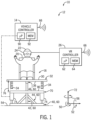
- an attraction 10 includes a ride vehicle control system 12 having a vehicle controller 14 and a ride vehicle 16 (e.g., a motion simulator).
- the ride vehicle 16 may include a seat 20 that is configured to accommodate a guest 22 (e.g., rider). While the guest 22 is in the ride vehicle 16, the guest 22 may also receive a virtual experience via a VR device 24 (e.g., VR headset, wearable visualization device, head-mounted sensor device) that includes or is coupled to a VR controller 26 (e.g., additional controller).
- a VR device 24 e.g., VR headset, wearable visualization device, head-mounted sensor device
- the ride vehicle 16 may take any suitable form or appearance, such as one including a sled, a motorcycle, a car, an animal, a surfboard, a skateboard, and so forth. Additionally, while the ride vehicle control system 12 is discussed herein with reference to the ride vehicle 16 that supports one guest 22 to facilitate discussion, it should be appreciated that similar techniques may be applied to adapt the ride vehicle control system 12 for a multi-passenger ride vehicle that supports multiple guests. It should also be appreciated that the VR device 24 is optional and may not be provided as part of the attraction 10.
- the VR controller 26 is not configured to coordinate the virtual experience, but instead may be utilized to receive signals from the head-mounted sensors that monitor the guest 22 and/or to provide the signals or other data (e.g., based on processing the signals from the head-mounted sensors) to the vehicle controller 14 (thus, the VR controller may be referred to as any type of additional controller, such as a guest-tracking controller, instead of the VR controller).
- the ride vehicle 16 may have any of a variety of configurations that enable the guest 22 to provide inputs (e.g., by moving their head, eyes, and/or body) to control movement of the ride vehicle 16.
- the seat 20 may be coupled to a top surface 30 of a spring plate 32 (e.g., solid plate; open framework) of the ride vehicle 16.
- Springs 34 may be engaged with or coupled to a bottom surface 36 of the spring plate 32.
- the springs 34 may provide resistance to movement of the spring plate 32 (e.g., relative to other components of the ride vehicle 16).
- the ride vehicle 16 may include a base 40 that is coupled to a support beam 42 via struts 44, and the support beam 42 is also coupled to the bottom surface 36 of the spring plate 32 via a pivot joint 46.
- the pivot joint 46 may enable the spring plate 32 to rotate via roll 50 (e.g., roll movement) and pitch 52 (e.g., pitch movement) relative to the base 40.
- the base 40 may be generally stationary relative to a ground surface 54.
- the base 40 may move relative to the ground surface 54, such as when the base 40 is part of a larger ride vehicle that traverses a path (e.g., a track).
- the pivot joint 46 may be a spherical bearing joint or universal joint that also enables the spring plate 32 to rotate via yaw 56 (e.g., yaw movement; about an axis that is parallel to a vertical axis 72) relative to the base 40.
- the pivot joint 46 may be configured to only enable movement along a single axis (e.g., corresponding to a single degree of freedom) or two axes (e.g., corresponding to two degrees of freedom), which may be suitable for simplified attractions.
- the pivot joint 46 may be a gimbal or a hinged gimbal expansion joint.
- the base 40, the support beam 42, and the pivot joint 46 generally form a support assembly 60 that supports the spring plate 32, while allowing one or more degrees of freedom of pivotal movement of the spring plate 32.
- the VR device 24 that may be worn by the guest 22 utilizes VR techniques, augmented reality (AR) techniques, and/or mixed reality (e.g., a combination of VR and AR) techniques to render a virtual experience for the guest 22.
- the VR controller 26 may include a processor 62 and a memory 64, and the processor 62 may execute instructions stored in the memory 64 to instruct a display of the VR device 24 to present a set of virtual images corresponding to the virtual experience.
- the VR controller 26 and the vehicle controller 14 may be communicatively coupled to one another via respective communication components 66 (e.g., wireless or wired). In this way, the virtual experience provided via the VR device 24 and motion of the ride vehicle 16 may be coordinated with one another.
- the ride elements may be virtual elements that are presented via the VR device 24.
- the ride elements may include real, physical elements within the attraction 10.
- the ride elements may include any of a variety of objects and/or effects, such as a road, a building, a character (e.g., an animal, robot), a flash of light, a sound, or the like.
- the ride cycle may include a first portion in which the actuator system 300 operates in the semi-passive mode with relatively low resistance (e.g., across a relatively low resistance range) to enable the guest 22 to control the movement of the ride vehicle 16 with relatively minor movements of their body (e.g., by shifting weight), and the ride cycle may include a second portion in which the actuator system 300 operates in the semi-passive mode with relatively high resistance (e.g., across a relatively high resistance range) to enable the guest 22 to control the movement of the ride vehicle 16 with relatively major movements of their body (e.g., by shifting weight).
- relatively low resistance e.g., across a relatively low resistance range
- relatively high resistance e.g., across a relatively high resistance range
- the intent of the guest 22 may be determined based on various factors (e.g., inputs; signals), such as the head position and/or movement, the eye position and/or movement, the body position and/or movement, and/or the ride elements.
- the vehicle controller 14 may input the various factors into algorithms, which may include lookup tables (e.g., that associate the various detected movements with corresponding changes to resistance and/or actions for the actuator system 300), to determine the intent of the guest 22.
- the algorithms may apply different weights to the various factors. For example, the position and/or movement of the head of the guest 22 may be weighted most heavily.
- machine learning may be utilized to associate the various factors with the intent.
- the vehicle controller 14 may access and/or identify characteristics of the guest 22 and may then control the actuator system 300 in a manner that is appropriate for the characteristics of the guest 22.
- the vehicle controller 14 may set the resistance to be appropriate for the characteristics of the guest 22, set limit positions (e.g., maximum roll, pitch, and/or yaw) of the spring plate 32 that are appropriate for the characteristics of the guest 22, a rate of change in position of the spring plate 32 when actively driving the spring plate 32, or the like.
- the vehicle controller 14 may switch from operating the ride vehicle 16 in the semi-passive mode to operating the ride vehicle 16 in the active mode in response to failing to detect shifting weight of the guest 22 and/or in response to failing to detect movement of the ride vehicle 16 (e.g., expected movement; in a direction) after determining the intent of the guest 22 is to move the ride vehicle 16 (e.g., in the direction). For example, after determining the intent based on signals indicative of one or more of movement of the head of the guest 22, movement of the eyes of the guest 22, a change in grip of the guest 22, and/or a change in limb positioning of the guest 22, the vehicle controller 14 may reduce the resistance to movement of the ride vehicle 16. However, if the ride vehicle 16 does not move within a time period after the reduction in the resistance, the vehicle controller 14 may switch to operating in the active mode and may drive movement of the ride vehicle 16 (e.g., in the direction).
- the characteristics of the guest 22 may be stored in a database (e.g., as a stored profile for the guest 22). An identifier of the guest 22 may be stored with the characteristics of the guest 22. Then, during subsequent rides by the guest 22, the vehicle controller 14 may access the characteristics from the database and may control the actuator system 300 in an appropriate manner for the guest 22 (e.g., without monitoring during the initial portion of the ride cycle and/or in addition to such monitoring). For example, the guest 22 may wear an identification device (e.g., a wearable device having a radiofrequency identification (RFID) tag that is unique to the guest 22).
- RFID radiofrequency identification
- an RFID reader that is communicatively coupled to the vehicle controller 14 may read the identifier (e.g., code) from the RFID tag when the guest 22 is in the ride vehicle 16, and the identifier may be associated and stored with the characteristics of the guest 22. Then, during the subsequent rides by the guest 22, the RFID reader may again read the identifier from the RFID tag, provide the identifier to the vehicle controller 14 so that the vehicle controller may access the characteristics for the guest 22 from the database. It should also be appreciated that the guest 22 may input the identifier and/or the characteristics via an input device (e.g., a touch screen on the ride vehicle 16 or in a queue for the attraction 10; prior to entering the amusement park).
- an input device e.g., a touch screen on the ride vehicle 16 or in a queue for the attraction 10; prior to entering the amusement park.
- the guest 22 may input preferences related to the resistance (e.g., low or high levels of resistance) and/or movement (e.g., low or high levels of movement) that they would like to experience in the ride vehicle 16.
- the preferences may be stored in the database and may be associated with the identifier.
- the vehicle controller 14 may also receive signals from one or more ride vehicle sensors 340, wherein the signals are indicative of a position (e.g., incline) and/or movement of the ride vehicle 16.
- the ride vehicle sensors 340 may include an inclinometer, an accelerometer, and/or a position sensor.
- the vehicle controller 14 may then control the actuator system 300 based on the signals from the one or more ride vehicle sensors 340 and the intent of the guest 22. In this way, the vehicle controller 14 may account for a current position of the ride vehicle 16 when controlling the actuator system 300 to reduce the resistance to movement of the spring plate 32 and/or to actively drive the spring plate 32.
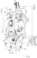
- the actuator system 300 may operate in a semi-passive mode to impart a resistance to movement of the spring plate 32 (e.g., via movement of the actuator plate 70 in FIG. 1 ; via torque output of the motors 220 in FIGS. 2 and 3 ).
- the vehicle controller 14 may refer to a resistance setting database 332 to determine a particular target resistance (e.g., that is appropriate for the characteristics of the guest 22 and/or the ride cycle) and settings for the actuator system 300 (e.g., the position of the actuator plate 70 in FIG. 1 ; the torque output of the motors 220 in FIGS. 2 and 3 ) to achieve the particular target resistance.
- the actuator system 300 may operate in an active mode in which the spring plate 32 is driven to move (e.g., in FIGS. 2 and 3 , one or more motors 220 are instructed to output a torque that overcomes the force imparted by the guest 22 onto the spring plate 32) to thereby position the spring plate 32.
- the vehicle controller 14 may operate the actuator system 300 to drive the spring plate 32 to move in a desirable manner (e.g., to a target position or orientation), instead of enabling the guest 22 to drive movement of the spring plate 32 (e.g., as in the semi-passive mode).
- the vehicle controller 14 may operate in the active mode to move the spring plate 32 and impart a certain sensation and ride experience to the guest 22.
- the vehicle controller 14 may be included in a housing or chassis of the ride vehicle 16, or the vehicle controller 14 may be remote to the ride vehicle 16 and coordinate operation of multiple ride vehicles 16.
- the vehicle controller 14 includes the processor 90 that provides instructions to the actuator system 300 and the memory 92 that stores the instructions for the processor 100.
- the memory 92 may also store the resistance setting database 332.
- the processor 90 may include one or more processors that can execute instructions for carrying out the presently disclosed techniques, such as a general-purpose processor, system-on-chip (SoC) device, an application-specific integrated circuit (ASIC), or some other similar processor configuration.
- these instructions are encoded in programs or code stored in a tangible, non-transitory, computer-readable medium, such as the memory 92 and/or other storage circuitry or device. It should be appreciated that processing steps and techniques disclosed herein may be carried out by the vehicle controller 14 alone or in conjunction within another controller that is communicatively coupled to the vehicle controller 14 (e.g., in conjunction with the VR controller 26 and/or any other type of additional controller, such as a guest tracking controller that receives, transmits, and/or processes signals indicative of the position and/or movement of the guest 22).
- a guest tracking controller that receives, transmits, and/or processes signals indicative of the position and/or movement of the guest 22.
- FIG. 5 is a flow diagram illustrating an embodiment of a method 400 for controlling the actuator system of the ride vehicle.
- the method 400 disclosed herein includes various steps represented by blocks. It should be noted that at least some steps of the method 400 may be performed as an automated procedure by a computing system, such as by the vehicle controller. Although the flow chart illustrates the steps in a certain sequence, it should be understood that the steps may be performed in any suitable order and certain steps may be carried out simultaneously, where appropriate. Additionally, steps may be added to or omitted from the method 400.
- the method 400 may begin by receiving signals indicative of a position and/or movement of a guest that is supported in the ride vehicle.
- the signals may include signals from a head position sensor, wherein the signals are indicative of a position and/or movement of a head of the guest. Additionally or alternatively, the signals may include signals from an eye position sensor, wherein the signals are indicative of a position and/or movement of one or both eyes of the guest. Additionally or alternatively, the signals may include signals from an array of weight sensors, wherein the signals are indicative of weight shifting of the guest. Additionally or alternatively, the signals may include signals from a grip sensor, wherein the signals are indicative of a grip strength, hand position, and/or hand movement of the guest.
- the method 400 may also include receiving signals indicative of a position (e.g., incline) of the ride vehicle.
- the signals may include signals from a ride vehicle sensor that is coupled to the ride vehicle, and the signals may be received at the vehicle controller.
- the method 400 may include controlling an actuator system based on the intent of the guest and the position of the ride vehicle.
- the vehicle controller may instruct the actuator system to adjust a resistance to movement of a spring plate of the ride vehicle to adjust the ride vehicle's response to weight shifting by the guest (e.g., to make it easier or to make it more difficult for the guest to rotate the spring plate).
- the vehicle controller may instruct the actuator system to actively drive the spring plate of the ride vehicle.
- the vehicle controller may carry out other steps, such as determining characteristics of the guest, accessing a resistance setting database, determining appropriate resistance settings based on the characteristics of the guest and/or ride cycle, and the like to provide a motion experience to the guest. Furthermore, the vehicle controller may control the actuator system so that the motion experience is coordinated with a visual experience, which may be presented to the guest via a VR device. For example, the vehicle controller may adjust the resistance to movement of the spring plate based on the visual experience (e.g., to provide less control to the guest during some portions of the ride cycle and to provide more control to the guest during other portions of the ride cycle).
- the disclosed ride vehicle control system includes enabling dynamic adjustment of a resistance of a ride vehicle and/or actively controlling movement of the ride vehicle based on various inputs from a guest in the ride vehicle.
- the disclosed ride vehicle control system provides an improved experience for guests having a wide range of characteristics.
- a ride vehicle control system for a ride vehicle of an attraction, the ride vehicle control system comprising a plurality of sensors configured to monitor a guest supported by the ride vehicle, an actuator system configured to couple to the ride vehicle, and one or more processors.
- the one or more processors are configured to receive signals from the plurality of sensors, wherein the signals are indicative of a position of the guest, a movement of the guest, or both, determine an intended movement for the ride vehicle based on the signals, and control the actuator system to adjust a resistance to movement of the ride vehicle, to adjust a force applied to the ride vehicle, or both to facilitate the intended movement.
- the plurality of sensors may comprise a head position sensor, and the signals may comprise one or more signals indicative of a head position of the guest, a head movement of the guest, or both.
- the plurality of sensors may comprise an eye position sensor, and the signals may comprise one or more signals indicative of an eye position of one or both eyes of the guest, an eye movement of the one or both eyes of the guest, or both.
- the actuator system may comprise one or more motors and one or more linkage systems that are configured to couple the one or more motors to the ride vehicle, wherein the one or more processors are configured to adjust the resistance to the movement of the ride vehicle by controlling an output torque of the one or more motors.
- the one or more processors may be configured to control presentation of virtual images to the guest via a VR device worn by the guest.
- the one or more processors may be configured to determine the intended movement for the ride vehicle based on the signals and the virtual images that are being presented to the guest via the VR device worn by the guest.
- the actuator system may be configured to operate in a semi-passive mode that enables the guest to move the ride vehicle by shifting their body weight.
- the ride vehicle control system comprises one or more processors configured to receive a first signal from a head position sensor, wherein the first signal is indicative of a position of a head of a guest, a movement of the head of the guest, or both, determine an intended movement for the ride vehicle based on the first signal, and control an actuator system to adjust a resistance to movement of the ride vehicle to facilitate the intended movement.
- the one or more processors may be configured to receive a second signal from an eye position sensor, wherein the second signal is indicative of an eye position of one or both eyes of the guest, an eye movement of the one or both eyes of the guest, or both, and determine the intended movement for the ride vehicle based on the first signal and the second signal.
- the one or more processors may be configured to receive a third signal from a grip sensor, wherein the third signal is indicative of a grip strength, a grip position of the guest, a grip movement of the guest, or any combination thereof, and determine the intended movement for the ride vehicle based on the first signal, the second signal, and the third signal.
- the one or more processors may be configured to receive a fourth signal from a skeletal sensor, wherein the fourth signal is indicative of a limb position of the guest, a limb movement of the guest, or both, and determine the intended movement for the ride vehicle based on the first signal, the second signal, and the fourth signal.
- the one or more processors may be configured to control presentation of virtual images to the guest via a VR device worn by the guest, and determine the intended movement for the ride vehicle based on the first signal and the virtual images that are being presented to the guest via the VR device worn by the guest.
- the ride vehicle control system may comprise the actuator system, wherein the actuator system comprises one or more motors, and one or more linkage systems that are configured to couple the one or more motors to the ride vehicle, wherein the one or more processors are configured to control an output torque of the one or more motors to adjust the resistance to the movement of the ride vehicle to facilitate the intended movement.
- the one or more processors may be configured to determine one or more characteristics of the guest, including a characteristic corresponding to a body weight of the guest, and control the actuator system to adjust the resistance based on the one or more characteristics of the guest to facilitate the intended movement.
- the one or more processors may be configured to determine the one or more characteristics of the guest during a calibration portion of a ride cycle.
- the one or more processors may be configured to operate the actuator system in a semi-passive mode to enable the guest to move the ride vehicle by shifting body weight.
- the one or more processors may be configured to operate the actuator system in an active mode to drive the ride vehicle in accordance with the intended movement.
- the method comprises receiving, at one or more processors, a first signal from a head position sensor, wherein the first signal is indicative of a position of a head of a guest, a movement of the head of the guest, or both, determining, using the one or more processors, an intended movement for a ride vehicle based on the first signal, and controlling, using the one or more processors, an actuator system to adjust a resistance to movement of the ride vehicle to facilitate the intended movement by the guest shifting body weight.
Landscapes
- Engineering & Computer Science (AREA)
- General Engineering & Computer Science (AREA)
- Theoretical Computer Science (AREA)
- Physics & Mathematics (AREA)
- General Physics & Mathematics (AREA)
- Human Computer Interaction (AREA)
- Computer Graphics (AREA)
- Computer Hardware Design (AREA)
- Software Systems (AREA)
- Vehicle Body Suspensions (AREA)
- Motorcycle And Bicycle Frame (AREA)
- Automatic Cycles, And Cycles In General (AREA)
Applications Claiming Priority (4)
| Application Number | Priority Date | Filing Date | Title |
|---|---|---|---|
| US202063077095P | 2020-09-11 | 2020-09-11 | |
| US17/470,118 US11747894B2 (en) | 2020-09-11 | 2021-09-09 | Systems and methods to facilitate guest control of a ride vehicle |
| PCT/US2021/049901 WO2022056284A1 (en) | 2020-09-11 | 2021-09-10 | Systems and methods to facilitate guest control of a ride vehicle |
| EP21790333.5A EP4210849B1 (de) | 2020-09-11 | 2021-09-10 | Systeme und verfahren zur erleichterung der gaststeuerung eines fahrgeschäfts |
Related Parent Applications (1)
| Application Number | Title | Priority Date | Filing Date |
|---|---|---|---|
| EP21790333.5A Division EP4210849B1 (de) | 2020-09-11 | 2021-09-10 | Systeme und verfahren zur erleichterung der gaststeuerung eines fahrgeschäfts |
Publications (2)
| Publication Number | Publication Date |
|---|---|
| EP4582159A2 true EP4582159A2 (de) | 2025-07-09 |
| EP4582159A3 EP4582159A3 (de) | 2025-09-24 |
Family
ID=80625703
Family Applications (2)
| Application Number | Title | Priority Date | Filing Date |
|---|---|---|---|
| EP21790333.5A Active EP4210849B1 (de) | 2020-09-11 | 2021-09-10 | Systeme und verfahren zur erleichterung der gaststeuerung eines fahrgeschäfts |
| EP25171072.9A Pending EP4582159A3 (de) | 2020-09-11 | 2021-09-10 | Systeme und verfahren zur erleichterung der gaststeuerung eines fahrgeschäfts |
Family Applications Before (1)
| Application Number | Title | Priority Date | Filing Date |
|---|---|---|---|
| EP21790333.5A Active EP4210849B1 (de) | 2020-09-11 | 2021-09-10 | Systeme und verfahren zur erleichterung der gaststeuerung eines fahrgeschäfts |
Country Status (8)
| Country | Link |
|---|---|
| US (2) | US11747894B2 (de) |
| EP (2) | EP4210849B1 (de) |
| JP (1) | JP7809695B2 (de) |
| KR (1) | KR20230066091A (de) |
| CN (1) | CN116322918A (de) |
| CA (1) | CA3189652A1 (de) |
| ES (1) | ES3034435T3 (de) |
| WO (1) | WO2022056284A1 (de) |
Families Citing this family (5)
| Publication number | Priority date | Publication date | Assignee | Title |
|---|---|---|---|---|
| US12079384B2 (en) | 2022-04-21 | 2024-09-03 | Universal City Studios Llc | Artificial intelligence (AI)-assisted and dynamic ride profile head tracking systems and methods |
| EP4729141A2 (de) | 2022-04-21 | 2026-04-22 | Universal City Studios LLC | Systeme und verfahren zur kopfverfolgung mit künstlicher intelligenz (ki) und dynamischem fahrprofil |
| US20230364523A1 (en) * | 2022-05-10 | 2023-11-16 | Universal City Studios Llc | Robotic arm integrated immersive reality |
| US20240226761A9 (en) * | 2022-10-21 | 2024-07-11 | Triotech Amusement Inc. | Apparatus and method for locking and unlocking a pointing device mounted on a car of an amusement park ride |
| US20250288915A1 (en) * | 2024-03-18 | 2025-09-18 | Universal City Studios Llc | Spatial audio adjustment system for an amusement ride |
Family Cites Families (26)
| Publication number | Priority date | Publication date | Assignee | Title |
|---|---|---|---|---|
| US5403238A (en) * | 1993-08-19 | 1995-04-04 | The Walt Disney Company | Amusement park attraction |
| JP4294089B2 (ja) * | 1993-08-19 | 2009-07-08 | ザ ウォルト ディズニー カンパニー | 動的な乗物 |
| JP2000342841A (ja) * | 1999-06-02 | 2000-12-12 | Namco Ltd | 遊戯装置 |
| JP2001017737A (ja) * | 1999-07-06 | 2001-01-23 | Snk Corp | バイクゲーム機 |
| JP3716134B2 (ja) * | 1999-07-13 | 2005-11-16 | 株式会社日立製作所 | 動揺装置の動作指令データ生成方法及び動揺装置 |
| US6733293B2 (en) * | 2001-01-26 | 2004-05-11 | Provision Entertainment, Inc. | Personal simulator |
| US7350787B2 (en) | 2001-04-03 | 2008-04-01 | Voss Darrell W | Vehicles and methods using center of gravity and mass shift control system |
| JP4813038B2 (ja) * | 2004-10-07 | 2011-11-09 | 川田工業株式会社 | 搭乗対象物傾動装置 |
| US7484460B2 (en) | 2005-09-30 | 2009-02-03 | Universal City Studios Lllp | Amusement ride track with motion base |
| US8226484B2 (en) | 2009-08-27 | 2012-07-24 | Nintendo Of America Inc. | Simulated handlebar twist-grip control of a simulated vehicle using a hand-held inertial sensing remote controller |
| CN102821730B (zh) | 2010-09-13 | 2015-09-30 | 松下知识产权经营株式会社 | 搭乘型移动体及搭乘型移动体的控制方法 |
| DE102010044024A1 (de) * | 2010-11-17 | 2012-05-24 | Bayerische Motoren Werke Aktiengesellschaft | Fahrassistenzsystem in einem Kraftfahrzeug |
| GB2492757B (en) | 2011-07-07 | 2015-12-23 | David Andrew Gale | A vehicle |
| US8684854B2 (en) * | 2011-10-31 | 2014-04-01 | Tait Towers Manufacturing, LLC | Suspended flying rig system |
| US9120021B2 (en) | 2013-04-10 | 2015-09-01 | Disney Enterprises, Inc. | Interactive lean sensor for controlling a vehicle motion system and navigating virtual environments |
| US20160001190A1 (en) | 2014-07-07 | 2016-01-07 | Tait Towers Manufacturing, LLC | Suspended flying rig system |
| DE102014113869A1 (de) * | 2014-09-24 | 2016-03-24 | Mack Rides Gmbh & Co. Kg | Vorrichtung zur Rückhaltung eines Fahrgastes in einer Halterung eines Fahrgeschäftes |
| WO2016085533A1 (en) * | 2014-11-26 | 2016-06-02 | Hogan Mfg., Inc. | Simulation device with motion stabilization |
| US10328897B1 (en) | 2015-09-25 | 2019-06-25 | Apple Inc. | Authorized remote control |
| WO2017135830A1 (en) | 2016-02-01 | 2017-08-10 | Manchester Securities Limited | Amusement ride |
| US10350504B2 (en) * | 2016-09-13 | 2019-07-16 | Universal City Studios Llc | Systems and methods for incorporating pneumatic robotic systems into amusement park attractions |
| US12153723B2 (en) * | 2017-03-06 | 2024-11-26 | Universal City Studios Llc | Systems and methods for layered virtual features in an amusement park environment |
| US10525364B2 (en) | 2017-11-07 | 2020-01-07 | Universal City Studios Llc | Speed simulation effect |
| US10636218B2 (en) * | 2018-09-24 | 2020-04-28 | Universal City Studios Llc | Augmented reality for an amusement ride |
| US10668391B1 (en) | 2018-12-04 | 2020-06-02 | Universal City Studios Llc | Ride control systems and methods for amusement park rides |
| US11033829B2 (en) * | 2019-08-21 | 2021-06-15 | Universal Studios LLC | Resistance control systems and methods for amusement attractions |
-
2021
- 2021-09-09 US US17/470,118 patent/US11747894B2/en active Active
- 2021-09-10 WO PCT/US2021/049901 patent/WO2022056284A1/en not_active Ceased
- 2021-09-10 CN CN202180062341.XA patent/CN116322918A/zh active Pending
- 2021-09-10 ES ES21790333T patent/ES3034435T3/es active Active
- 2021-09-10 CA CA3189652A patent/CA3189652A1/en active Pending
- 2021-09-10 EP EP21790333.5A patent/EP4210849B1/de active Active
- 2021-09-10 EP EP25171072.9A patent/EP4582159A3/de active Pending
- 2021-09-10 JP JP2023515847A patent/JP7809695B2/ja active Active
- 2021-09-10 KR KR1020237012286A patent/KR20230066091A/ko active Pending
-
2023
- 2023-07-20 US US18/224,488 patent/US12130961B2/en active Active
Also Published As
| Publication number | Publication date |
|---|---|
| US20230359269A1 (en) | 2023-11-09 |
| US12130961B2 (en) | 2024-10-29 |
| EP4210849A1 (de) | 2023-07-19 |
| JP2023540789A (ja) | 2023-09-26 |
| KR20230066091A (ko) | 2023-05-12 |
| JP7809695B2 (ja) | 2026-02-02 |
| EP4210849B1 (de) | 2025-05-07 |
| WO2022056284A1 (en) | 2022-03-17 |
| ES3034435T3 (en) | 2025-08-18 |
| CA3189652A1 (en) | 2022-03-17 |
| CN116322918A (zh) | 2023-06-23 |
| EP4582159A3 (de) | 2025-09-24 |
| US11747894B2 (en) | 2023-09-05 |
| US20220083132A1 (en) | 2022-03-17 |
Similar Documents
| Publication | Publication Date | Title |
|---|---|---|
| US12130961B2 (en) | Systems and methods to facilitate guest control of a ride vehicle | |
| US11712796B2 (en) | Robot that acts comically, and structure thereof | |
| KR101726902B1 (ko) | 햅틱 피드백에 의해 특정 움직임을 시뮬레이션하기 위한 방법, 및 방법을 구현하는 장치 | |
| US12079384B2 (en) | Artificial intelligence (AI)-assisted and dynamic ride profile head tracking systems and methods | |
| CN114222611A (zh) | 用于游乐景点的阻力控制系统和方法 | |
| US12560996B2 (en) | Artificial intelligence (AI)-assisted and dynamic ride profile head tracking systems and methods | |
| JP2025083365A (ja) | 娯楽用アトラクションのための抵抗制御システム及び方法 | |
| KR101364594B1 (ko) | 사용자의 움직임과 모션 플랫폼 사이의 양방향 상호 작용을 기반으로 한 실감형 스노보드 장치 및 그 제어방법. | |
| HK40096006A (zh) | 用以促进乘坐交通工具的顾客控制的系统和方法 | |
| JP2025502320A (ja) | アトラクションシステムの乗り物車両を制御するためのシステムおよび方法 | |
| KR101968043B1 (ko) | 다중체험이 가능한 가상현실 인터랙션 모듈시스템 | |
| JP3770278B2 (ja) | シミュレータのロック装置 | |
| HK40120385A (zh) | 人工智能(ai)辅助和动态乘坐简档头部跟踪系统和方法 | |
| HK40071800A (en) | Resistance control systems and methods for amusement attractions |
Legal Events
| Date | Code | Title | Description |
|---|---|---|---|
| PUAI | Public reference made under article 153(3) epc to a published international application that has entered the european phase |
Free format text: ORIGINAL CODE: 0009012 |
|
| STAA | Information on the status of an ep patent application or granted ep patent |
Free format text: STATUS: THE APPLICATION HAS BEEN PUBLISHED |
|
| AC | Divisional application: reference to earlier application |
Ref document number: 4210849 Country of ref document: EP Kind code of ref document: P |
|
| AK | Designated contracting states |
Kind code of ref document: A2 Designated state(s): AL AT BE BG CH CY CZ DE DK EE ES FI FR GB GR HR HU IE IS IT LI LT LU LV MC MK MT NL NO PL PT RO RS SE SI SK SM TR |
|
| REG | Reference to a national code |
Ref country code: DE Ref legal event code: R079 Free format text: PREVIOUS MAIN CLASS: A63G0031160000 Ipc: A63G0007000000 |
|
| PUAL | Search report despatched |
Free format text: ORIGINAL CODE: 0009013 |
|
| AK | Designated contracting states |
Kind code of ref document: A3 Designated state(s): AL AT BE BG CH CY CZ DE DK EE ES FI FR GB GR HR HU IE IS IT LI LT LU LV MC MK MT NL NO PL PT RO RS SE SI SK SM TR |
|
| RIC1 | Information provided on ipc code assigned before grant |
Ipc: A63G 7/00 20060101AFI20250821BHEP Ipc: A63G 31/16 20060101ALI20250821BHEP |
|
| STAA | Information on the status of an ep patent application or granted ep patent |
Free format text: STATUS: REQUEST FOR EXAMINATION WAS MADE |
|
| 17P | Request for examination filed |
Effective date: 20260309 |