EP4582126A1 - Integrated breathing circuit - Google Patents
Integrated breathing circuit Download PDFInfo
- Publication number
- EP4582126A1 EP4582126A1 EP24217022.3A EP24217022A EP4582126A1 EP 4582126 A1 EP4582126 A1 EP 4582126A1 EP 24217022 A EP24217022 A EP 24217022A EP 4582126 A1 EP4582126 A1 EP 4582126A1
- Authority
- EP
- European Patent Office
- Prior art keywords
- breathing
- coupling member
- suction tube
- housing
- coupled
- Prior art date
- Legal status (The legal status is an assumption and is not a legal conclusion. Google has not performed a legal analysis and makes no representation as to the accuracy of the status listed.)
- Pending
Links
Images




Classifications
-
- A—HUMAN NECESSITIES
- A61—MEDICAL OR VETERINARY SCIENCE; HYGIENE
- A61M—DEVICES FOR INTRODUCING MEDIA INTO, OR ONTO, THE BODY; DEVICES FOR TRANSDUCING BODY MEDIA OR FOR TAKING MEDIA FROM THE BODY; DEVICES FOR PRODUCING OR ENDING SLEEP OR STUPOR
- A61M16/00—Devices for influencing the respiratory system of patients by gas treatment, e.g. ventilators; Tracheal tubes
- A61M16/08—Bellows; Connecting tubes ; Water traps; Patient circuits
- A61M16/0808—Condensation traps
-
- A—HUMAN NECESSITIES
- A61—MEDICAL OR VETERINARY SCIENCE; HYGIENE
- A61M—DEVICES FOR INTRODUCING MEDIA INTO, OR ONTO, THE BODY; DEVICES FOR TRANSDUCING BODY MEDIA OR FOR TAKING MEDIA FROM THE BODY; DEVICES FOR PRODUCING OR ENDING SLEEP OR STUPOR
- A61M16/00—Devices for influencing the respiratory system of patients by gas treatment, e.g. ventilators; Tracheal tubes
- A61M16/08—Bellows; Connecting tubes ; Water traps; Patient circuits
-
- A—HUMAN NECESSITIES
- A61—MEDICAL OR VETERINARY SCIENCE; HYGIENE
- A61M—DEVICES FOR INTRODUCING MEDIA INTO, OR ONTO, THE BODY; DEVICES FOR TRANSDUCING BODY MEDIA OR FOR TAKING MEDIA FROM THE BODY; DEVICES FOR PRODUCING OR ENDING SLEEP OR STUPOR
- A61M16/00—Devices for influencing the respiratory system of patients by gas treatment, e.g. ventilators; Tracheal tubes
- A61M16/08—Bellows; Connecting tubes ; Water traps; Patient circuits
- A61M16/0816—Joints or connectors
- A61M16/0841—Joints or connectors for sampling
- A61M16/0858—Pressure sampling ports
-
- A—HUMAN NECESSITIES
- A61—MEDICAL OR VETERINARY SCIENCE; HYGIENE
- A61M—DEVICES FOR INTRODUCING MEDIA INTO, OR ONTO, THE BODY; DEVICES FOR TRANSDUCING BODY MEDIA OR FOR TAKING MEDIA FROM THE BODY; DEVICES FOR PRODUCING OR ENDING SLEEP OR STUPOR
- A61M16/00—Devices for influencing the respiratory system of patients by gas treatment, e.g. ventilators; Tracheal tubes
- A61M16/20—Valves specially adapted to medical respiratory devices
-
- G—PHYSICS
- G01—MEASURING; TESTING
- G01F—MEASURING VOLUME, VOLUME FLOW, MASS FLOW OR LIQUID LEVEL; METERING BY VOLUME
- G01F1/00—Measuring the volume flow or mass flow of fluid or fluent solid material wherein the fluid passes through a meter in a continuous flow
- G01F1/05—Measuring the volume flow or mass flow of fluid or fluent solid material wherein the fluid passes through a meter in a continuous flow by using mechanical effects
- G01F1/34—Measuring the volume flow or mass flow of fluid or fluent solid material wherein the fluid passes through a meter in a continuous flow by using mechanical effects by measuring pressure or differential pressure
- G01F1/36—Measuring the volume flow or mass flow of fluid or fluent solid material wherein the fluid passes through a meter in a continuous flow by using mechanical effects by measuring pressure or differential pressure the pressure or differential pressure being created by the use of flow constriction
-
- A—HUMAN NECESSITIES
- A61—MEDICAL OR VETERINARY SCIENCE; HYGIENE
- A61M—DEVICES FOR INTRODUCING MEDIA INTO, OR ONTO, THE BODY; DEVICES FOR TRANSDUCING BODY MEDIA OR FOR TAKING MEDIA FROM THE BODY; DEVICES FOR PRODUCING OR ENDING SLEEP OR STUPOR
- A61M16/00—Devices for influencing the respiratory system of patients by gas treatment, e.g. ventilators; Tracheal tubes
- A61M16/04—Tracheal tubes
- A61M16/0463—Tracheal tubes combined with suction tubes, catheters or the like; Outside connections
-
- A—HUMAN NECESSITIES
- A61—MEDICAL OR VETERINARY SCIENCE; HYGIENE
- A61M—DEVICES FOR INTRODUCING MEDIA INTO, OR ONTO, THE BODY; DEVICES FOR TRANSDUCING BODY MEDIA OR FOR TAKING MEDIA FROM THE BODY; DEVICES FOR PRODUCING OR ENDING SLEEP OR STUPOR
- A61M16/00—Devices for influencing the respiratory system of patients by gas treatment, e.g. ventilators; Tracheal tubes
- A61M16/08—Bellows; Connecting tubes ; Water traps; Patient circuits
- A61M16/0875—Connecting tubes
-
- A—HUMAN NECESSITIES
- A61—MEDICAL OR VETERINARY SCIENCE; HYGIENE
- A61M—DEVICES FOR INTRODUCING MEDIA INTO, OR ONTO, THE BODY; DEVICES FOR TRANSDUCING BODY MEDIA OR FOR TAKING MEDIA FROM THE BODY; DEVICES FOR PRODUCING OR ENDING SLEEP OR STUPOR
- A61M16/00—Devices for influencing the respiratory system of patients by gas treatment, e.g. ventilators; Tracheal tubes
- A61M16/20—Valves specially adapted to medical respiratory devices
- A61M16/201—Controlled valves
-
- A—HUMAN NECESSITIES
- A61—MEDICAL OR VETERINARY SCIENCE; HYGIENE
- A61M—DEVICES FOR INTRODUCING MEDIA INTO, OR ONTO, THE BODY; DEVICES FOR TRANSDUCING BODY MEDIA OR FOR TAKING MEDIA FROM THE BODY; DEVICES FOR PRODUCING OR ENDING SLEEP OR STUPOR
- A61M16/00—Devices for influencing the respiratory system of patients by gas treatment, e.g. ventilators; Tracheal tubes
- A61M16/0003—Accessories therefor, e.g. sensors, vibrators, negative pressure
- A61M2016/003—Accessories therefor, e.g. sensors, vibrators, negative pressure with a flowmeter
-
- A—HUMAN NECESSITIES
- A61—MEDICAL OR VETERINARY SCIENCE; HYGIENE
- A61M—DEVICES FOR INTRODUCING MEDIA INTO, OR ONTO, THE BODY; DEVICES FOR TRANSDUCING BODY MEDIA OR FOR TAKING MEDIA FROM THE BODY; DEVICES FOR PRODUCING OR ENDING SLEEP OR STUPOR
- A61M16/00—Devices for influencing the respiratory system of patients by gas treatment, e.g. ventilators; Tracheal tubes
- A61M16/0003—Accessories therefor, e.g. sensors, vibrators, negative pressure
- A61M2016/003—Accessories therefor, e.g. sensors, vibrators, negative pressure with a flowmeter
- A61M2016/0033—Accessories therefor, e.g. sensors, vibrators, negative pressure with a flowmeter electrical
-
- A—HUMAN NECESSITIES
- A61—MEDICAL OR VETERINARY SCIENCE; HYGIENE
- A61M—DEVICES FOR INTRODUCING MEDIA INTO, OR ONTO, THE BODY; DEVICES FOR TRANSDUCING BODY MEDIA OR FOR TAKING MEDIA FROM THE BODY; DEVICES FOR PRODUCING OR ENDING SLEEP OR STUPOR
- A61M16/00—Devices for influencing the respiratory system of patients by gas treatment, e.g. ventilators; Tracheal tubes
- A61M16/0003—Accessories therefor, e.g. sensors, vibrators, negative pressure
- A61M2016/003—Accessories therefor, e.g. sensors, vibrators, negative pressure with a flowmeter
- A61M2016/0033—Accessories therefor, e.g. sensors, vibrators, negative pressure with a flowmeter electrical
- A61M2016/0036—Accessories therefor, e.g. sensors, vibrators, negative pressure with a flowmeter electrical in the breathing tube and used in both inspiratory and expiratory phase
Definitions
- the housing comprises a first end coupled to a first breathing tube of the plurality of breathing tubes and an opposing second end coupled to a second breathing tube of the plurality of breathing tubes.
- the one or more connectors comprise one or more secure leak-proof connectors.
- the one or more valves are configured for regulating removal of contamination within the flow sensor via the suction tube assembly.
- the housing comprises a first housing and a second housing, wherein a first coupling member of the first set of coupling members extends from the first housing, and a second coupling member of the first set of coupling members extends from the second housing.
- each of the first coupling member and the second coupling member comprises a luer lock fitting.
- the first coupling member is coupled to a first suction tube of the suction tube assembly, such that a first suction pathway is defined
- the second coupling member is coupled to a second suction tube of the suction tube assembly, such that a second suction pathway is defined.
- a first valve of the one or more valves is disposed between the first coupling member and the first suction tube, and a second valve of the one or more valves is disposed between the second coupling member and the second suction tube.
- an end of a third suction tube of the suction tube assembly is coupled to the first suction tube and the second suction tube via a connector.
- an opposing end of the suction tube assembly is configured for being coupled to a suction device.
- a breathing system comprises a breathing circuit comprising a plurality of breathing tubes; a flow sensor coupled to the breathing circuit, the flow sensor comprising a housing defining a flow channel and having at least one reservoir and a plurality of coupling members, wherein each coupling member of the plurality of coupling members defines an opening therethrough; and a suction tube assembly, wherein: a first set of coupling members of the plurality of coupling members is coupled to an end of the suction tube assembly via one or more connectors, and one or more valves are disposed between the first set of coupling members and the suction tube assembly.
- the one or more connectors comprise one or more secure leak-proof connectors.
- the one or more valves are configured for regulating removal of contamination within the flow sensor via the suction tube assembly.
- the housing comprises a first housing having a first reservoir and a second housing having a second reservoir.
- a first coupling member of the first set of coupling members extends from the first reservoir, and a second coupling member of the first set of coupling members extends from the second reservoir.
- each of the first coupling member and the second coupling member comprises a luer lock fitting.
- the first coupling member is coupled to a first suction tube of the suction tube assembly, such that a first suction pathway is defined
- the second coupling member is coupled to a second suction tube of the suction tube assembly, such that a second suction pathway is defined.
- a first valve of the one or more valves is disposed between the first coupling member and the first suction tube, and a second valve of the one or more valves is disposed between the second coupling member and the second suction tube.
- an opposing end of the suction tube assembly is configured for being coupled to a suction device.
- ком ⁇ онент or feature may,” “can,” “could,” “should,” “would,” “preferably,” “possibly,” “typically,” “optionally,” “for example,” “often,” or “might” (or other such language) be included or have a characteristic, that a specific component or feature is not required to be included or to have the characteristic. Such a component or feature may be optionally included in some embodiments, or it may be excluded.
- the term "example” or “exemplary” means serving as an example, instance, or illustration. Any aspect or design described herein as "exemplary” is not necessarily to be construed as preferred or advantageous over other aspects or designs. Rather, use of the word exemplary is intended to present concepts in a concrete fashion.
- a particular feature may be disclosed with respect to only one of several implementations, such feature may be combined with one or more other features of the other implementations as may be desired and advantageous for any given or particular application.
- the terms “includes” and “including” and variants thereof are used in either the detailed description or the claims, these terms are intended to be inclusive in a manner similar to the term “comprising.”
- the term “or” is used in both the alternative and conjunctive sense, unless otherwise indicated.
- the terms “illustrative” and “example” are used to be examples with no indication of quality level.
- Terms such as “computing,” “determining,” “generating,” and/or similar words are used herein interchangeably to refer to the creation, modification, or identification of data.
- “based on,” “based on in part on,” “based at least on,” “based upon,” and/or similar words are used herein interchangeably in an open-ended manner such that they do not indicate being based only on or based solely on the referenced element or elements unless so indicated.
- Like numbers refer to like elements throughout.
- Coupled refers to both direct coupling, fixing, or attaching, as well as indirect coupling, fixing, or attaching through one or more intermediate components or features, unless otherwise specified herein.
- terms of approximation such as “approximately,” “substantially,” or “about,” refer to being within manufacturing or engineering tolerances. For example, terms of approximation may refer to being withing a five percent margin of error.
- a breathing circuit may be configured to direct the flow of breathing gas to a patient.
- a breathing circuit may be used in an intubation procedure to provide respiration assistance to a patient.
- Breathing gas may be supplied to the patient via the breathing circuit and a flow sensor may be attached to the breathing circuit to measure the flow rate.
- a flow sensor may be attached to the breathing circuit to measure the flow rate.
- Applicant has identified various deficiencies associated with breathing circuits. For example, when a patient is invasively intubated, a tube is passed down through the patient's throat. Mucus and/or other substances may flow out of the tube into a flow sensor attached to the breathing circuit.
- a humidifier may be leveraged to maintain air flowing through the breathing circuit at a certain temperature and humidity level.
- the humidified air may condense inside the flow sensor or breathing circuit due to temperature differential between ambient air flowing through the circuit.
- Contamination, such as mucus, condensation, and/or the like within the flow sensor may cause the flow sensor to fail or otherwise adversely impact the performance of the flow sensor.
- operation of internal component(s) of the flow sensor may be impaired, resulting in inaccurate flow rate measurement and/or other parameters.
- Embodiments of the present disclosure address the above-mentioned challenges and difficulties, as well as other challenges and difficulties associated with breathing circuits.
- Embodiments of the present disclosure provide a breathing system comprising a breathing circuit with a flow sensor integrated therein, that allows for removal of contamination (e.g., mucus, condensation, and/or the like) from the flow sensor without taking apart the breathing circuit.
- contamination e.g., mucus, condensation, and/or the like
- embodiments of the present disclosure allow for removal of contamination from the sensor while the patient is using the breathing system.
- Some embodiments of the present disclosure include a suction tube assembly attached to the flow sensor.
- the suction tube assembly may be configured for being coupled to a suction device (e.g., a suction machine) configured to suck out contamination from the flow sensor via the suction tube assembly.
- a suction device e.g., a suction machine
- Some embodiments of the present disclosure include one or more reservoirs configured to allow for more contamination to be collected before the need to clean the sensor, which, in turn, increases the time to failure of the sensor.
- embodiments of the present disclosure prevent exposure of the patient to adverse environment conditions, prevents exposure of medical providers to the medical conditions associated with a patient, increases the performance (e.g., time to failure) of the flow sensor, and reduces the amount of resources that would otherwise be utilized to take the breathing circuit apart and clean (or replace) the flow sensor.
- FIG. 1 is a schematic illustration of a portion of an example breathing system 100 in accordance with at least one example embodiment of the present disclosure.
- the breathing system 100 may include a breathing circuit 110 and at least one flow sensor 150 integrated within the breathing circuit 110.
- a flow sensor 150 may be coupled, directly or indirectly, between at least two components of the breathing circuit 110.
- the breathing system 100 includes a suction tube assembly 190.
- the suction tube assembly 190 may be, directly or indirectly, coupled to the flow sensor 150.
- the suction tube assembly 190 may be configured to facilitate removal of contamination from the flow sensor 150.
- the breathing circuit 110 may include a plurality of breathing tubes 112 through which gas flows into and out of the flow sensor 150.
- the plurality of breathing tubes 112 may be made from a variety of materials.
- the plurality of breathing tubes 112 may be made from, plastics, composites, and/or the like.
- one or more of the plurality of breathing tubes 112 may be flexible.
- one or more of the plurality of breathing tubes 112 may be rigid.
- one or more of the plurality of breathing tubes 112 may be transparent.
- one or more of the plurality of breathing tubes 112 may be translucent.
- one of the first breathing tube 112a or the second breathing tube 112b may be configured for coupling, directly or indirectly, to a ventilator device (e.g., via one or more connectors), while the other of the first breathing tube 112a or second breathing tube 112b may be configured for coupling, directly or indirectly, to a user (e.g., a medical patient).
- a ventilator device e.g., via one or more connectors
- the other of the first breathing tube 112a or second breathing tube 112b may be configured for coupling, directly or indirectly, to a user (e.g., a medical patient).
- a user e.g., a medical patient
- an opposing end of the first breathing tube 112a may be configured for coupling, directly or indirectly, to a ventilator device
- an opposing end of the second breathing tube 112b may be configured for coupling, directly or indirectly, to a user.
- an opposing end of the second breathing tube 112b may be configured for coupling, directly or indirectly, to a ventilator device, while an opposing end of the second breathing tube 112b may be configured for coupling, directly or indirectly, to a user.
- the breathing circuit may comprise different configurations in some examples.
- the first and second breathing tubes may be coaxial (e.g., one breathing tube inside the other breathing tube) in some examples.
- the breathing circuit may comprise only a single tube in some examples.
- FIG. 2a is a schematic illustration of a flow sensor 150 in accordance with at least one example embodiment of the present disclosure.
- FIG. 2b is a schematic illustration of a flow sensor 150 in accordance with at least one example embodiment of the present disclosure.
- the flow sensor 150 may be a proximal flow sensor based on a differential pressure principle.
- the flow sensor 150 may describe a passive flow differential pressure converter configured for measuring of gas flow (e.g., breathing gas flow).
- the flow sensor 150 may comprise a housing 152 defining a flow channel 154.
- the flow channel 154 may define a flow path in a plane that is parallel (e.g., substantially parallel) to a horizontal-axis 101 defined by the housing 152.
- gas may flow through the flow channel 154 from the first breathing tube 112a to the second breathing tube 112b (or vice versa) along the flow path.
- the first housing 152a may comprise a body 158a and the second housing 152b may comprise a body 158b.
- the body 158a of the first housing 152a may comprise a first body portion 160a and a second body portion 160b.
- the second body portion 160b may have a diameter that is smaller than the diameter of the first body portion 160a.
- the body 158b of the second housing 152b may comprise a first body portion 162a and second body portion 162b.
- the second body portion 162b may have a diameter that is smaller than the diameter of the first body portion 162a.
- the diameter of the first body portion 160a of the first housing 152a and the diameter of the first body portion 162a of the second housing 152b may be substantially the same. In various embodiments, the diameter of the first body portion 160a of the first housing 152a and the diameter of the first body portion 162a of the second housing 152b may be different. In various embodiments, the diameter of the second body portion 160b of the first housing 152a and the diameter of the second body portion 162b of the second housing 152b may be substantially the same. In various embodiments, the diameter of the second body portion 160b of the first housing 152a and the diameter of the second body portion 162b of the second housing 152b may be different.
- the housing 152 comprises a plurality of coupling members. Each coupling member of the plurality of coupling members may define an opening therethrough. In various embodiments, a set of one or more coupling members of the plurality of coupling member is configured to facilitate flow measurement. For example, the set of one or more coupling members may be configured for coupling the flow sensor 150 to sensor tube(s), where the sensor tube(s) may be coupled to one or more differential pressure measurement devices.
- each of the first housing 152a and the second housing 152b may comprise at least one coupling member. As shown in FIGS. 2a and 2b , the first housing 152a comprises a first coupling member 156a and the second housing 152b comprises a second coupling member 156b. In various embodiments, each of the first coupling member 156a and the second coupling member 156b may be configured for coupling the housing 152 to a sensor tube. In various embodiments, the first coupling member 156a may be coupled to a first sensor tube 114a such that the first coupling member 156a opens into the first sensor tube 114a. In various embodiments, the second coupling member 156b may be coupled to a second sensor tube 114b such that the second coupling member 156b opens into the second sensor tube 114b.
- a respective opposing end of the first sensor tube 114a and the second sensor tube 114b may be configured for coupling, via one or more connectors, to a measuring unit comprising one or more differential pressure measurement devices (e.g., differential pressure measurement gauges).
- the first coupling member 156a and/or the second coupling member 156b is positioned perpendicular (e.g., substantially perpendicular) with respect to the horizontal-axis 101. It would be appreciated that in some embodiments, the first coupling member 156a and/or the second coupling member 156b may be positioned at an angle with respect to the horizontal-axis 101 defined by the housing 152, where the noted angle is not a perpendicular.
- the first coupling member 156a may extend perpendicularly from the first body portion 160a of the first housing 152a and the second coupling member 156b may extend perpendicularly from the first body portion 162a of the second housing 152b.
- the first coupling member 156a and the second coupling member 156b have substantially the same diameter. It would be appreciated that in some embodiments, the diameter of the first coupling member 156a and the diameter of the second coupling member 156b may be different.
- the flow sensor 150 may include at least one flow resistance element (not shown) positioned within the housing 152.
- the at least one flow resistance element may be positioned within the flow sensor 150 in the area where the first housing 152a and second housing 152b meet.
- a flow resistance element may be positioned substantially parallel to the vertical-axis defined by the housing 152 (thus, positioned substantially perpendicular to the horizontal axis defined by the housing 152, which corresponds to the flow path within the flow channel 154 of the housing 152.
- the flow resistance element may be leveraged to determine the difference in pressure upstream of the flow resistance element and downstream of the flow resistance element.
- the flow resistance element may be leveraged to determine the difference in pressure within the first housing 152a and the second housing 152b.
- a flow resistance element may comprise a sheet, a film, or the like, and may be made from a variety of materials (e.g., plastic, composite, and/or the like).
- a flow resistance element may be embodied as a flexible flap having a circular shape.
- the flow resistance element may comprise a narrow slit.
- the one or more flow resistance elements may comprise other configurations.
- a flow resistance element may have a non-circular shape profile.
- a set of one or more coupling members of the plurality of coupling members of the housing 152 may be configured to facilitate removal of contamination (e.g., contamination, mucus, and/or the like) from the flow sensor 150.
- the housing 152 may comprise a third coupling member 182a and a fourth coupling member 182b.
- the third coupling member 182a and the fourth coupling member 182b may each be configured to facilitate removal of contamination. As shown in FIGS.
- the third coupling member 182a and the fourth coupling member 182b may extend from the body 158a and the body 158b respectively in a direction opposite the direction in which the first coupling member 156a and second coupling member 156b extend from the body 158a and the body 158b, respectively.
- the housing 152 may comprise a set of one or more coupling members configured to facilitate flow measurement, and a set of one or more coupling configured to facilitate removal of contamination from the flow sensor, where the sets of one or more coupling members are positioned on opposite sides of the housing 152.
- the third coupling member 182a may extend from the first body portion 160a of the body 158a and the fourth coupling member 182b may extend from the first body portion 162a of the body 158b. As shown in FIG. 2a . in some embodiments, the third coupling member 182a may extend perpendicular from the body 158a (e.g., first body portion 160a thereof) and the fourth coupling member 182b may extend perpendicular from the body 158b (e.g., first body portion 162a thereof). As shown in FIG 2b .
- the third coupling member 182a may extend at an angle that is not perpendicular with respect to the body 158a (e.g., first body portion 160a thereof) and the fourth coupling member 182b may extend at an angle that is not perpendicular with respect to the body 158b (e.g., first body portion 162a thereof).
- each of the third coupling member 182a and fourth coupling member 182b may extend from the body 158a and the body 158b respectively, such that the third coupling member 182a extends away with respect to the vertical axis 102 defined by the housing 152 and the fourth coupling member 182b extends away with respect to the vertical axis 102.
- each of the third coupling member 182a and fourth coupling member 182b may extend from the body 158a and the body 158b respectively, such that the third coupling member 182a extends towards with respect to the vertical axis 102 defined by the housing 152 and the fourth coupling member 182b extends towards with respect to the vertical axis 102.
- Each of the third coupling member 182a and the fourth coupling member 182b may define an opening therethrough (e.g., channel), such that contamination within the flow sensor 150 may be transmitted out of the flow sensor 150 via the third coupling member 182a and the fourth coupling member 182b.
- the third coupling member 182a and the fourth coupling member 182b have substantially the same diameter. It would be appreciated that in some embodiments, the diameter of the third coupling member 182a and the diameter of the fourth coupling member 182b may be different.
- the breathing system 100 includes a suction tube assembly 190.
- Each of the third coupling member 182a and the fourth coupling member 182b may be configured for coupling, directly or indirectly the flow sensor 150 to the suction tube assembly 190.
- the third coupling member 182a is coupled to a first suction tube of the suction tube assembly, such that a first suction pathway is defined
- the fourth coupling member 182b is coupled to a second suction tube of the suction tube assembly, such that a second suction pathway is defined.
- a secure leak-free connection configuration is leveraged to couple the third coupling member 182a and the fourth coupling member 182b to the suction tube assembly 190.
- the third coupling member 182a and the fourth coupling member 182b may comprise a luer lock fitting configured to facilitate secure leak-proof connection between each of the third coupling member 182a and the fourth coupling member 182b and the suction tube assembly.
- each of the third coupling member 182a and fourth coupling member 182b may comprise one or more ridges 202 along the outer surface configured to facilitate a secure leak-proof coupling.
- Each of the third coupling member 182a and the fourth coupling member 182b may comprise a male luer lock fitting configured to mate with a corresponding female luer lock fitting 308. It would be appreciated that in some embodiments, each of the third coupling member 182a and the fourth coupling member 182b may comprise a female luer lock fitting configured to mate with a corresponding male luer lock fitting. It would be appreciated that in some embodiments, the third coupling member 182a and the fourth coupling member 182b may comprise a secure leak proof coupling configuration that is different from a luer lock configuration.
- FIG. 3 schematically illustrates a portion of a breathing system 100 showing a suction tube assembly 190 in accordance with at least one example embodiment of the present disclosure.
- the suction tube assembly 190 may comprise one or more suction tubes.
- an end of a first suction tube 302a of the suction tube assembly 190 may be coupled to the third coupling member 182a and an end of second suction tube 302b of the suction tube assembly 190 may be coupled to the fourth coupling member 182b.
- One or more connectors and/or one or more valves may be leveraged to couple the first suction tube 302a to the third coupling member 182a and the second suction tube 302b to the fourth coupling member 182b.
- the one or more connectors comprise luer lock fittings, such as female luer lock fitting 308.
- opposing ends of the first suction tube 302a and the second suction tube 302b may be configured for being coupled to a suction device.
- a first valve 306a of the one or more valves is disposed between the first coupling member and the first suction tube, and a second valve 306b of the one or more valves is disposed between the second coupling member and the second suction tube.
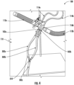
- FIG. 4 schematically illustrates a portion of a breathing system 100 showing a suction tube assembly 190 in accordance with at least one example embodiment of the present disclosure.
- the opposing ends of the first suction tube 302a and the second suction tube 302b may be coupled to a splitter such as a "Y" fitting 310.
- a splitter such as a "Y" fitting 310.
- an end of a third suction tube 302c of the suction tube assembly 190 may be coupled to the tail portion tail portion of a "Y" fitting 310.
- the opposing end of the third suction tube 302c may be configured for being coupled to the suction device.
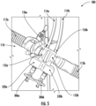
- FIG. 5 schematically illustrates a portion of a breathing system 100 comprising a flow sensor 500 having one or more reservoirs in accordance with at least one example embodiment of the present disclosure.
- the flow sensor 500 may comprise several of the same components that have been described above in connection to the flow sensor 150. Therefore, a repeated description of the similar component are omitted.
- the flow sensor 150 includes at least one reservoir configured for receiving mucus, condensation, and/or other contamination.
- the housing 152 may comprise a first reservoir 520a and a second reservoir 520b.
- the first reservoir 520a may be disposed opposite the first coupling member 156a and the second reservoir 520b may be disposed opposite the second coupling member 156b.
- the third coupling member 182a and the fourth coupling member 182b may extend from the first reservoir 520a and the second reservoir 520b respectively in a direction opposite the direction in which the first coupling member 156a and the second coupling member 156b extend from the body 158a and the body 158b, respectively.
- each of the third coupling member 182a and fourth coupling member 182b may extend from the first reservoir 520a and the second reservoir 520b respectively, such that the third coupling member 182a extends away with respect to the vertical axis 102 defined by the housing 152 and the fourth coupling member 182b extends away with respect to the vertical axis 102.
- each of the third coupling member 182a and fourth coupling member 182b may extend from the first reservoir 520a and the second reservoir 520b respectively, such that the third coupling member 182a extends towards with respect to the vertical axis 102 defined by the housing 152 and the fourth coupling member 182b extends towards with respect to the vertical axis 102.
- Each of the third coupling member 182a and the fourth coupling member 182b may define an opening therethrough (e.g., channel), such that contamination within the flow sensor 150 include contamination collected in the first reservoir 520a and the second reservoir 520b may be transmitted out of the first reservoir 520a and the second reservoir 520b via the third coupling member 182a and the fourth coupling member 182b respectively.
- FIG. 6 illustrates a flowchart depicting operations of an example process for removing contamination from a flow sensor integrated within a breathing circuit in accordance with at least one example embodiment of the present disclosure. Specifically, FIG. 6 depicts an example process 600. Although the example processes depicts a particular sequence of operations, the sequence may be altered without departing from the scope of the present disclosure. For example, some of the operations depicted may be performed in parallel or in a different sequence that does not materially affect the function of the processes.
- the blocks indicate operations of each process. Such operations may be performed in any of a number of ways, including, without limitation, in the order and manner as depicted and described herein. In some embodiments, one or more blocks of any of the processes described herein occur in-between one or more blocks of another process, before one or more blocks of another process, in parallel with one or more blocks of another process, and/or as a sub-process of a second process. Additionally or alternatively, any of the processes in various embodiments include some or all operational steps described and/or depicted, including one or more optional blocks in some embodiments. With regard to the flowcharts illustrated herein, one or more of the depicted block(s) in some embodiments is/are optional in some, or all, embodiments of the disclosure. Optional blocks are depicted with broken (or "dashed") lines. Similarly, it should be appreciated that one or more of the operations of each flowchart may be combinable, replaceable, and/or otherwise altered as described herein.
- the method includes coupling one or more breathing tubes of the breathing circuit to one or more external devices at block 602.
- the at least one breathing tube may be coupled to the one or more external devices via one or more connectors and/or adapters.
- one or more breathing tubes are connected to a ventilator device.
- an end of the at least one breathing tube may be coupled to the ventilator device, wherein the opposing end of the breathing tube is coupled to the flow sensor integrated within the breathing circuit.
- the flow sensor may be disposed between a pair of breathing tubes.
- a first end of the flow sensor may be coupled to a first end of first breathing tube and a second end of the flow sensor may be coupled to a first end of a second breathing tube, where a second end of the first breathing tube may be coupled to a ventilator device, and a second end of the second breathing tube may be configured for interaction with a user or coupled to other components configured for interaction with the user.
- a portion of the second breathing tube may be configured for being inserted into a user's mouth.
- the method includes coupling one or more sensor tubes to a measuring unit at block 604.
- the measuring unit comprising one or more differential pressure measurement devices.
- the measuring unit may comprise differential pressure measurement gauges.
- the one or more sensors may be coupled to the measuring unit via one or more connectors.
- the measuring unit is embodied within the ventilator device.
- the one or more sensor tubes may be coupled to the ventilator device via one or more connectors.
- the method includes coupling the flow sensor to a suction device at block 606.
- the flow sensor may be coupled to a suction tube assembly (e.g., comprising one or more suction tubes) at one end of the suction tube assembly, where the suction tube assembly is coupled to the suction device via an opposing end of the suction device.
- the suction tube assembly is coupled to the flow sensor via one or more coupling members of the flow sensor.
- the one or more coupling members may each define an opening therethrough, such that a flow path is created between the flow sensor and the suction tube assembly.
- the one or coupling members may be coupled to the suction tube assembly via one or more connectors.
- a luer lock fitting connection may be leveraged to couple the flow sensor to suction tube assembly.
- one or more valves are disposed between the flow sensor and the one or more suction valves.
- the one or more suction valves may be configured to regulate opening, closing, and/or partial obstruction of one or more flow paths defined by the flow sensor and the suction tube assembly.
- the method includes causing removal of contamination from the flow sensor via suction at block 608.
- causing removal of contamination from the flow sensor comprises opening a valve positioned between the flow sensor and the suction tube assembly coupled to the suction device.
- causing removal of contamination from the flow sensor comprises switching the suction device from an OFF state to an ON state (e.g., operation state of the suction device).
- FIGS. 7a and 7b depict results of an example experimental simulation conducted to verify the effectiveness of embodiments as described herein.
- FIG 7a depicts results of an example simulation conducted using a breathing system in accordance with at least one embodiment described herein.
- FIG. 7b depicts results of an example simulation conducted using a breathing circuit configuration without contamination removal as described herein.
- the simulation result comprise a plot, wherein the y-axis represents pressure measurement 702, and the x-axis represents time 704.
- the contamination removal configuration of the simulated example embodiment brings the flow sensor back within the example specification following contamination (e.g., by humidity) of the flow sensor as compared to the FIG. 7b (without suction).
- the flow sensor failed at a fast rate.
- the ability to suction in accordance with at least one embodiment of the present disclosure increases the time to failure and reduces medical provider intervention.
Landscapes
- Health & Medical Sciences (AREA)
- Life Sciences & Earth Sciences (AREA)
- General Health & Medical Sciences (AREA)
- Engineering & Computer Science (AREA)
- Anesthesiology (AREA)
- Biomedical Technology (AREA)
- Heart & Thoracic Surgery (AREA)
- Hematology (AREA)
- Emergency Medicine (AREA)
- Pulmonology (AREA)
- Public Health (AREA)
- Animal Behavior & Ethology (AREA)
- Veterinary Medicine (AREA)
- Physics & Mathematics (AREA)
- Fluid Mechanics (AREA)
- General Physics & Mathematics (AREA)
- Measuring Fluid Pressure (AREA)
- Measurement Of The Respiration, Hearing Ability, Form, And Blood Characteristics Of Living Organisms (AREA)
Abstract
A breathing system, comprising a breathing circuit comprising a plurality of breathing tubes; a flow sensor coupled to the breathing circuit, the flow sensor comprising a housing defining a flow channel and having a plurality of coupling members, wherein each coupling member of the plurality of coupling members defines an opening therethrough; and a suction tube assembly. A first set of coupling members of the plurality of coupling members is coupled to an end of the suction tube assembly via one or more connectors, one or more valves are disposed between the first set of coupling members and the suction tube assembly.
Description
- The present application relates generally to a breathing circuit. More specifically, the present application relates generally to a breathing circuit having a flow sensor integrated within the breathing circuit.
- A breathing circuit may be configured to direct the flow of breathing gas to a patient. For example, a breathing circuit may be used in an intubation procedure to provide respiration assistance to a patient.
- The inventors have identified numerous deficiencies and problems with breathing circuits. Through applied effort, ingenuity, and innovation, many of these identified deficiencies and problems have been solved by developing solutions that are structured in accordance with the embodiments of the present disclosure, many examples of which are described in detail herein.
- In accordance with one aspect of the present disclosure, a breathing system is provided. The example breathing system includes a breathing circuit comprising a plurality of breathing tubes; a flow sensor coupled to the breathing circuit, the flow sensor comprising a housing defining a flow channel and having a plurality of coupling members, wherein each coupling member of the plurality of coupling members defines an opening therethrough; and a suction tube assembly, wherein: a first set of coupling members of the plurality of coupling members is coupled to an end of the suction tube assembly via one or more connectors, and one or more valves are disposed between the first set of coupling members and the suction tube assembly.
- In some embodiments, the housing comprises a first end coupled to a first breathing tube of the plurality of breathing tubes and an opposing second end coupled to a second breathing tube of the plurality of breathing tubes.
- In some embodiments, the one or more connectors comprise one or more secure leak-proof connectors.
- In some embodiments, the one or more valves are configured for regulating removal of contamination within the flow sensor via the suction tube assembly.
- In some embodiments, the housing comprises a first housing and a second housing, wherein a first coupling member of the first set of coupling members extends from the first housing, and a second coupling member of the first set of coupling members extends from the second housing.
- In some embodiments, each of the first coupling member and the second coupling member comprises a luer lock fitting.
- In some embodiments, the first coupling member is coupled to a first suction tube of the suction tube assembly, such that a first suction pathway is defined, and the second coupling member is coupled to a second suction tube of the suction tube assembly, such that a second suction pathway is defined.
- In some embodiments, a first valve of the one or more valves is disposed between the first coupling member and the first suction tube, and a second valve of the one or more valves is disposed between the second coupling member and the second suction tube.
- In some embodiments, an end of a third suction tube of the suction tube assembly is coupled to the first suction tube and the second suction tube via a connector.
- In some embodiments, an opposing end of the suction tube assembly is configured for being coupled to a suction device.
- In accordance with one aspect of the present disclosure, a breathing system is provided. The breathing system, comprises a breathing circuit comprising a plurality of breathing tubes; a flow sensor coupled to the breathing circuit, the flow sensor comprising a housing defining a flow channel and having at least one reservoir and a plurality of coupling members, wherein each coupling member of the plurality of coupling members defines an opening therethrough; and a suction tube assembly, wherein: a first set of coupling members of the plurality of coupling members is coupled to an end of the suction tube assembly via one or more connectors, and one or more valves are disposed between the first set of coupling members and the suction tube assembly.
- In some embodiments, the housing comprises a first end coupled to a first breathing tube of the plurality of breathing tubes and an opposing second end coupled to a second breathing tube of the plurality of breathing tubes.
- In some embodiments, the one or more connectors comprise one or more secure leak-proof connectors.
- In some embodiments, the one or more valves are configured for regulating removal of contamination within the flow sensor via the suction tube assembly.
- In some embodiments, the housing comprises a first housing having a first reservoir and a second housing having a second reservoir.
- In some embodiments, a first coupling member of the first set of coupling members extends from the first reservoir, and a second coupling member of the first set of coupling members extends from the second reservoir.
- In some embodiments, each of the first coupling member and the second coupling member comprises a luer lock fitting.
- In some embodiments, the first coupling member is coupled to a first suction tube of the suction tube assembly, such that a first suction pathway is defined, and the second coupling member is coupled to a second suction tube of the suction tube assembly, such that a second suction pathway is defined.
- In some embodiments, a first valve of the one or more valves is disposed between the first coupling member and the first suction tube, and a second valve of the one or more valves is disposed between the second coupling member and the second suction tube.
- In some embodiments, an opposing end of the suction tube assembly is configured for being coupled to a suction device.
- The above summary is provided merely for purposes of summarizing some example embodiments to provide a basic understanding of some aspects of the present disclosure. Accordingly, it will be appreciated that the above-described embodiments are merely examples and should not be construed to narrow the scope or spirit of the present disclosure in any way. It will be appreciated that the scope of the present disclosure encompasses many potential embodiments in addition to those here summarized, some of which will be further described below. Other features, aspects, and advantages of the subject matter will become apparent from the description, the drawings, and the claims.
- Having thus described certain example embodiments of the present disclosure in general terms above, non-limiting and non-exhaustive embodiments of the subject disclosure are described with reference to the following figures, which are not necessarily drawn to scale and wherein like reference numerals refer to like parts throughout the various views unless otherwise specified. The components illustrated in the figures may or may not be present in certain embodiments described herein. Some embodiments may include fewer (or more) components than those shown in the figures.
-
FIG. 1 schematically illustrates a portion of an example breathing system in accordance with at least one example embodiment of the present disclosure. -
FIGS. 2A is a schematic illustration of an example flow sensor of an example breathing system in accordance with at least one example embodiment of the present disclosure. -
FIG. 2B is a schematic illustration of an example flow sensor of an example breathing system in accordance with at least one example embodiment of the present disclosure. -
FIG. 3 schematically illustrates a portion of an example breathing system showing a suction tube assembly in accordance with at least one example embodiment of the present disclosure. -
FIG. 4 schematically illustrates a portion of a breathing system showing a suction tube assembly in accordance with at least one example embodiment of the present disclosure. -
FIG. 5 schematically illustrates a portion of a breathing system having reservoirs in accordance with at least one example embodiment of the present disclosure. -
FIG. 6 illustrates a flowchart depicting operations of an example process for removing contamination from a flow sensor of an example breathing system in accordance with at least one example embodiment of the present disclosure. -
FIGS. 7A-7B provides an example simulation result plot. - One or more embodiments are now more fully described with reference to the accompanying drawings, wherein like reference numerals are used to refer to like elements throughout and in which some, but not all embodiments of the inventions are shown. In the following description, for purposes of explanation, numerous specific details are set forth in order to provide a thorough understanding of the various embodiments. It is evident, however, that the various embodiments can be practiced without these specific details. It should be understood that some, but not all embodiments are shown and described herein. Indeed, the embodiments may be embodied in many different forms, and accordingly this disclosure should not be construed as limited to the embodiments set forth herein. Rather, these embodiments are provided so that this disclosure will satisfy applicable legal requirements.
- As used herein, the term "comprising" means including but not limited to and should be interpreted in the manner it is typically used in the patent context. Use of broader terms such as comprises, includes, and having should be understood to provide support for narrower terms such as consisting of, consisting essentially of, and comprised substantially of.
- As used herein, the phrases "in one embodiment," "according to one embodiment," "in some embodiments," and the like generally mean that the particular feature, structure, or characteristic following the phrase may be included in at least one embodiment of the present disclosure, and may be included in more than one embodiment of the present disclosure (importantly, such phrases do not necessarily refer to the same embodiment).
- If the specification states a component or feature "may," "can," "could," "should," "would," "preferably," "possibly," "typically," "optionally," "for example," "often," or "might" (or other such language) be included or have a characteristic, that a specific component or feature is not required to be included or to have the characteristic. Such a component or feature may be optionally included in some embodiments, or it may be excluded.
- As used herein, the term "example" or "exemplary" means serving as an example, instance, or illustration. Any aspect or design described herein as "exemplary" is not necessarily to be construed as preferred or advantageous over other aspects or designs. Rather, use of the word exemplary is intended to present concepts in a concrete fashion. In addition, while a particular feature may be disclosed with respect to only one of several implementations, such feature may be combined with one or more other features of the other implementations as may be desired and advantageous for any given or particular application. Furthermore, to the extent that the terms "includes" and "including" and variants thereof are used in either the detailed description or the claims, these terms are intended to be inclusive in a manner similar to the term "comprising."
- As used herein, the term "or" is used in both the alternative and conjunctive sense, unless otherwise indicated. The terms "illustrative" and "example" are used to be examples with no indication of quality level. Terms such as "computing," "determining," "generating," and/or similar words are used herein interchangeably to refer to the creation, modification, or identification of data. Further, "based on," "based on in part on," "based at least on," "based upon," and/or similar words are used herein interchangeably in an open-ended manner such that they do not indicate being based only on or based solely on the referenced element or elements unless so indicated. Like numbers refer to like elements throughout.
- As used herein, the terms "coupled," "fixed," "attached to," and the like refer to both direct coupling, fixing, or attaching, as well as indirect coupling, fixing, or attaching through one or more intermediate components or features, unless otherwise specified herein.
- As used herein, terms of approximation, such as "approximately," "substantially," or "about," refer to being within manufacturing or engineering tolerances. For example, terms of approximation may refer to being withing a five percent margin of error.
- A breathing circuit may be configured to direct the flow of breathing gas to a patient. For example, a breathing circuit may be used in an intubation procedure to provide respiration assistance to a patient. Breathing gas may be supplied to the patient via the breathing circuit and a flow sensor may be attached to the breathing circuit to measure the flow rate. As described above Applicant has identified various deficiencies associated with breathing circuits. For example, when a patient is invasively intubated, a tube is passed down through the patient's throat. Mucus and/or other substances may flow out of the tube into a flow sensor attached to the breathing circuit.
- Moreover, in various applications, a humidifier may be leveraged to maintain air flowing through the breathing circuit at a certain temperature and humidity level. The humidified air may condense inside the flow sensor or breathing circuit due to temperature differential between ambient air flowing through the circuit. Contamination, such as mucus, condensation, and/or the like within the flow sensor may cause the flow sensor to fail or otherwise adversely impact the performance of the flow sensor. For example, operation of internal component(s) of the flow sensor may be impaired, resulting in inaccurate flow rate measurement and/or other parameters.
- To remove the mucus (and/or other substance) and the condensation, existing solutions require a medical provider to take the breathing circuit apart and clean the flow sensor, which exposes the patient to environmental conditions, and also exposes the medical provider to the medical condition the patient may have. Generally, the medical provider has to use a separate component (e.g., detached from the breathing circuit) to clean out the flow sensor, re-attach the sensor to the breathing circuit, and re-attach the breathing circuit to the patient. Additionally, flooding of the flow sensor can lead to stoppage of therapy, increased operational effort for clinicians, and increase in waste due to discarding flooded flow sensors.
- Embodiments of the present disclosure address the above-mentioned challenges and difficulties, as well as other challenges and difficulties associated with breathing circuits. Embodiments of the present disclosure provide a breathing system comprising a breathing circuit with a flow sensor integrated therein, that allows for removal of contamination (e.g., mucus, condensation, and/or the like) from the flow sensor without taking apart the breathing circuit. Moreover, embodiments of the present disclosure allow for removal of contamination from the sensor while the patient is using the breathing system.
- Some embodiments of the present disclosure include a suction tube assembly attached to the flow sensor. The suction tube assembly may be configured for being coupled to a suction device (e.g., a suction machine) configured to suck out contamination from the flow sensor via the suction tube assembly. Some embodiments of the present disclosure include one or more reservoirs configured to allow for more contamination to be collected before the need to clean the sensor, which, in turn, increases the time to failure of the sensor. By providing for cleaning the flow sensor without taking the breathing circuit apart, embodiments of the present disclosure prevent exposure of the patient to adverse environment conditions, prevents exposure of medical providers to the medical conditions associated with a patient, increases the performance (e.g., time to failure) of the flow sensor, and reduces the amount of resources that would otherwise be utilized to take the breathing circuit apart and clean (or replace) the flow sensor.
-
FIG. 1 is a schematic illustration of a portion of anexample breathing system 100 in accordance with at least one example embodiment of the present disclosure. As shown inFIG. 1 , thebreathing system 100 may include abreathing circuit 110 and at least oneflow sensor 150 integrated within thebreathing circuit 110. For example, aflow sensor 150 may be coupled, directly or indirectly, between at least two components of thebreathing circuit 110. In various embodiments, thebreathing system 100 includes asuction tube assembly 190. Thesuction tube assembly 190 may be, directly or indirectly, coupled to theflow sensor 150. In various embodiments, thesuction tube assembly 190 may be configured to facilitate removal of contamination from theflow sensor 150. - The
breathing circuit 110 may include a plurality ofbreathing tubes 112 through which gas flows into and out of theflow sensor 150. The plurality ofbreathing tubes 112 may be made from a variety of materials. For example, the plurality ofbreathing tubes 112 may be made from, plastics, composites, and/or the like. In some embodiments, one or more of the plurality ofbreathing tubes 112 may be flexible. In some embodiments, one or more of the plurality ofbreathing tubes 112 may be rigid. In some embodiments, one or more of the plurality ofbreathing tubes 112 may be transparent. In some embodiments, one or more of the plurality ofbreathing tubes 112 may be translucent. - The
breathing circuit 110 may include one or more connectors and/or one or more adapters. The one or more connectors and/or one or more adapters may be configured for coupling at least a portion of the plurality ofbreathing tubes 112 to one or more other components of thebreathing system 100 and/or to one or more other devices. In various embodiments, and as shown inFIG. 1 , an end of afirst breathing tube 112a of the plurality ofbreathing tubes 112 may be coupled to theflow sensor 150 via afirst adapter 116a, and an end of asecond breathing tube 112b of the plurality ofbreathing tubes 112 may be coupled to theflow sensor 150 via asecond adapter 116b. In various embodiments, one of thefirst breathing tube 112a or thesecond breathing tube 112b may be configured for coupling, directly or indirectly, to a ventilator device (e.g., via one or more connectors), while the other of thefirst breathing tube 112a orsecond breathing tube 112b may be configured for coupling, directly or indirectly, to a user (e.g., a medical patient). For example, an opposing end of thefirst breathing tube 112a may be configured for coupling, directly or indirectly, to a ventilator device, while an opposing end of thesecond breathing tube 112b may be configured for coupling, directly or indirectly, to a user. For example, an opposing end of thesecond breathing tube 112b may be configured for coupling, directly or indirectly, to a ventilator device, while an opposing end of thesecond breathing tube 112b may be configured for coupling, directly or indirectly, to a user. It would be appreciated that the breathing circuit may comprise different configurations in some examples. For example, the first and second breathing tubes may be coaxial (e.g., one breathing tube inside the other breathing tube) in some examples. As another example, the breathing circuit may comprise only a single tube in some examples. -
FIG. 2a is a schematic illustration of aflow sensor 150 in accordance with at least one example embodiment of the present disclosure.FIG. 2b is a schematic illustration of aflow sensor 150 in accordance with at least one example embodiment of the present disclosure. Theflow sensor 150 may be a proximal flow sensor based on a differential pressure principle. For example, theflow sensor 150 may describe a passive flow differential pressure converter configured for measuring of gas flow (e.g., breathing gas flow). Theflow sensor 150 may comprise ahousing 152 defining aflow channel 154. In various embodiments, theflow channel 154 may define a flow path in a plane that is parallel (e.g., substantially parallel) to a horizontal-axis 101 defined by thehousing 152. For example, gas may flow through theflow channel 154 from thefirst breathing tube 112a to thesecond breathing tube 112b (or vice versa) along the flow path. - In various embodiments, the
housing 152 comprises afirst housing 152a and asecond housing 152b. Thefirst housing 152a and thesecond housing 152b may be coupled together at a respective end portion of thefirst housing 152a and thesecond housing 152b. Each of the flow first housing and thesecond housing 152b may define a cavity therein. In various embodiments, theflow sensor 150 may be configured to determine the gas flow (e.g., flow rate) based on the differential pressure between thefirst housing 152a cavity and thesecond housing 152b cavity. For example, the differential pressure between thefirst housing 152a and thesecond housing 152b may be converted to a flow rate. - The
first housing 152a may comprise abody 158a and thesecond housing 152b may comprise abody 158b. Thebody 158a of thefirst housing 152a may comprise afirst body portion 160a and asecond body portion 160b. Thesecond body portion 160b may have a diameter that is smaller than the diameter of thefirst body portion 160a. Thebody 158b of thesecond housing 152b may comprise afirst body portion 162a andsecond body portion 162b. Thesecond body portion 162b may have a diameter that is smaller than the diameter of thefirst body portion 162a. - In various embodiments, the diameter of the
first body portion 160a of thefirst housing 152a and the diameter of thefirst body portion 162a of thesecond housing 152b may be substantially the same. In various embodiments, the diameter of thefirst body portion 160a of thefirst housing 152a and the diameter of thefirst body portion 162a of thesecond housing 152b may be different. In various embodiments, the diameter of thesecond body portion 160b of thefirst housing 152a and the diameter of thesecond body portion 162b of thesecond housing 152b may be substantially the same. In various embodiments, the diameter of thesecond body portion 160b of thefirst housing 152a and the diameter of thesecond body portion 162b of thesecond housing 152b may be different. - In various embodiments, the
housing 152 comprises a plurality of coupling members. Each coupling member of the plurality of coupling members may define an opening therethrough. In various embodiments, a set of one or more coupling members of the plurality of coupling member is configured to facilitate flow measurement. For example, the set of one or more coupling members may be configured for coupling theflow sensor 150 to sensor tube(s), where the sensor tube(s) may be coupled to one or more differential pressure measurement devices. - In various embodiments, each of the
first housing 152a and thesecond housing 152b may comprise at least one coupling member. As shown inFIGS. 2a and 2b , thefirst housing 152a comprises afirst coupling member 156a and thesecond housing 152b comprises asecond coupling member 156b. In various embodiments, each of thefirst coupling member 156a and thesecond coupling member 156b may be configured for coupling thehousing 152 to a sensor tube. In various embodiments, thefirst coupling member 156a may be coupled to afirst sensor tube 114a such that thefirst coupling member 156a opens into thefirst sensor tube 114a. In various embodiments, thesecond coupling member 156b may be coupled to asecond sensor tube 114b such that thesecond coupling member 156b opens into thesecond sensor tube 114b. - A respective opposing end of the
first sensor tube 114a and thesecond sensor tube 114b may be configured for coupling, via one or more connectors, to a measuring unit comprising one or more differential pressure measurement devices (e.g., differential pressure measurement gauges). In some embodiments, thefirst coupling member 156a and/or thesecond coupling member 156b is positioned perpendicular (e.g., substantially perpendicular) with respect to the horizontal-axis 101. It would be appreciated that in some embodiments, thefirst coupling member 156a and/or thesecond coupling member 156b may be positioned at an angle with respect to the horizontal-axis 101 defined by thehousing 152, where the noted angle is not a perpendicular. - In some embodiments, and as shown in
FIGS. 2a and 2b , thefirst coupling member 156a may extend perpendicularly from thefirst body portion 160a of thefirst housing 152a and thesecond coupling member 156b may extend perpendicularly from thefirst body portion 162a of thesecond housing 152b. In various embodiments, thefirst coupling member 156a and thesecond coupling member 156b have substantially the same diameter. It would be appreciated that in some embodiments, the diameter of thefirst coupling member 156a and the diameter of thesecond coupling member 156b may be different. - The
flow sensor 150 may include at least one flow resistance element (not shown) positioned within thehousing 152. The at least one flow resistance element may be positioned within theflow sensor 150 in the area where thefirst housing 152a andsecond housing 152b meet. For example, a flow resistance element may be positioned substantially parallel to the vertical-axis defined by the housing 152 (thus, positioned substantially perpendicular to the horizontal axis defined by thehousing 152, which corresponds to the flow path within theflow channel 154 of thehousing 152. The flow resistance element may be leveraged to determine the difference in pressure upstream of the flow resistance element and downstream of the flow resistance element. For example, the flow resistance element may be leveraged to determine the difference in pressure within thefirst housing 152a and thesecond housing 152b. A flow resistance element may comprise a sheet, a film, or the like, and may be made from a variety of materials (e.g., plastic, composite, and/or the like). In some embodiments, a flow resistance element may be embodied as a flexible flap having a circular shape. In some embodiments, the flow resistance element may comprise a narrow slit. It would be appreciated that in other embodiments, the one or more flow resistance elements may comprise other configurations. For example, in some embodiments, a flow resistance element may have a non-circular shape profile. - A set of one or more coupling members of the plurality of coupling members of the
housing 152 may be configured to facilitate removal of contamination (e.g., contamination, mucus, and/or the like) from theflow sensor 150. For example, thehousing 152 may comprise athird coupling member 182a and afourth coupling member 182b. Thethird coupling member 182a and thefourth coupling member 182b may each be configured to facilitate removal of contamination. As shown inFIGS. 2a and 2b , thethird coupling member 182a and thefourth coupling member 182b may extend from thebody 158a and thebody 158b respectively in a direction opposite the direction in which thefirst coupling member 156a andsecond coupling member 156b extend from thebody 158a and thebody 158b, respectively. For example, thehousing 152 may comprise a set of one or more coupling members configured to facilitate flow measurement, and a set of one or more coupling configured to facilitate removal of contamination from the flow sensor, where the sets of one or more coupling members are positioned on opposite sides of thehousing 152. - The
third coupling member 182a may extend from thefirst body portion 160a of thebody 158a and thefourth coupling member 182b may extend from thefirst body portion 162a of thebody 158b. As shown inFIG. 2a . in some embodiments, thethird coupling member 182a may extend perpendicular from thebody 158a (e.g.,first body portion 160a thereof) and thefourth coupling member 182b may extend perpendicular from thebody 158b (e.g.,first body portion 162a thereof). As shown inFIG 2b . in some embodiments, thethird coupling member 182a may extend at an angle that is not perpendicular with respect to thebody 158a (e.g.,first body portion 160a thereof) and thefourth coupling member 182b may extend at an angle that is not perpendicular with respect to thebody 158b (e.g.,first body portion 162a thereof). As shown inFIG. 2b , each of thethird coupling member 182a andfourth coupling member 182b may extend from thebody 158a and thebody 158b respectively, such that thethird coupling member 182a extends away with respect to thevertical axis 102 defined by thehousing 152 and thefourth coupling member 182b extends away with respect to thevertical axis 102. It would be appreciated that in some embodiments, each of thethird coupling member 182a andfourth coupling member 182b may extend from thebody 158a and thebody 158b respectively, such that thethird coupling member 182a extends towards with respect to thevertical axis 102 defined by thehousing 152 and thefourth coupling member 182b extends towards with respect to thevertical axis 102. - Each of the
third coupling member 182a and thefourth coupling member 182b may define an opening therethrough (e.g., channel), such that contamination within theflow sensor 150 may be transmitted out of theflow sensor 150 via thethird coupling member 182a and thefourth coupling member 182b. In various embodiments, thethird coupling member 182a and thefourth coupling member 182b have substantially the same diameter. It would be appreciated that in some embodiments, the diameter of thethird coupling member 182a and the diameter of thefourth coupling member 182b may be different. - As described above, in various embodiments, the
breathing system 100 includes asuction tube assembly 190. Each of thethird coupling member 182a and thefourth coupling member 182b may be configured for coupling, directly or indirectly theflow sensor 150 to thesuction tube assembly 190. In various embodiments, thethird coupling member 182a is coupled to a first suction tube of the suction tube assembly, such that a first suction pathway is defined, and thefourth coupling member 182b is coupled to a second suction tube of the suction tube assembly, such that a second suction pathway is defined. - In various embodiments, a secure leak-free connection configuration is leveraged to couple the
third coupling member 182a and thefourth coupling member 182b to thesuction tube assembly 190. In some embodiments, and as shown inFIGS. 2a and 2b , thethird coupling member 182a and thefourth coupling member 182b may comprise a luer lock fitting configured to facilitate secure leak-proof connection between each of thethird coupling member 182a and thefourth coupling member 182b and the suction tube assembly. - For example, and as shown in
FIGS 2a and 2b , a portion of the outer surface of each of thethird coupling member 182a andfourth coupling member 182b may comprise one ormore ridges 202 along the outer surface configured to facilitate a secure leak-proof coupling. Each of thethird coupling member 182a and thefourth coupling member 182b may comprise a male luer lock fitting configured to mate with a corresponding female luer lock fitting 308. It would be appreciated that in some embodiments, each of thethird coupling member 182a and thefourth coupling member 182b may comprise a female luer lock fitting configured to mate with a corresponding male luer lock fitting. It would be appreciated that in some embodiments, thethird coupling member 182a and thefourth coupling member 182b may comprise a secure leak proof coupling configuration that is different from a luer lock configuration. -
FIG. 3 schematically illustrates a portion of abreathing system 100 showing asuction tube assembly 190 in accordance with at least one example embodiment of the present disclosure. Thesuction tube assembly 190 may comprise one or more suction tubes. As shown inFIG. 3 , an end of afirst suction tube 302a of thesuction tube assembly 190 may be coupled to thethird coupling member 182a and an end ofsecond suction tube 302b of thesuction tube assembly 190 may be coupled to thefourth coupling member 182b. One or more connectors and/or one or more valves may be leveraged to couple thefirst suction tube 302a to thethird coupling member 182a and thesecond suction tube 302b to thefourth coupling member 182b. In some embodiments, the one or more connectors comprise luer lock fittings, such as female luer lock fitting 308. In various embodiments, opposing ends of thefirst suction tube 302a and thesecond suction tube 302b may be configured for being coupled to a suction device. In some embodiments, afirst valve 306a of the one or more valves is disposed between the first coupling member and the first suction tube, and asecond valve 306b of the one or more valves is disposed between the second coupling member and the second suction tube. -
FIG. 4 schematically illustrates a portion of abreathing system 100 showing asuction tube assembly 190 in accordance with at least one example embodiment of the present disclosure. In some embodiments, and as shown inFIG. 4 , the opposing ends of thefirst suction tube 302a and thesecond suction tube 302b may be coupled to a splitter such as a "Y" fitting 310. For example, as shown inFIG. 4 , an end of athird suction tube 302c of thesuction tube assembly 190 may be coupled to the tail portion tail portion of a "Y" fitting 310. The opposing end of thethird suction tube 302c may be configured for being coupled to the suction device. -
FIG. 5 schematically illustrates a portion of abreathing system 100 comprising aflow sensor 500 having one or more reservoirs in accordance with at least one example embodiment of the present disclosure. Theflow sensor 500 may comprise several of the same components that have been described above in connection to theflow sensor 150. Therefore, a repeated description of the similar component are omitted. - In various embodiments, the
flow sensor 150 includes at least one reservoir configured for receiving mucus, condensation, and/or other contamination. As shown inFIG. 5 , thehousing 152 may comprise afirst reservoir 520a and asecond reservoir 520b. Thefirst reservoir 520a may be disposed opposite thefirst coupling member 156a and thesecond reservoir 520b may be disposed opposite thesecond coupling member 156b. As shown inFIG. 5 , thethird coupling member 182a and thefourth coupling member 182b may extend from thefirst reservoir 520a and thesecond reservoir 520b respectively in a direction opposite the direction in which thefirst coupling member 156a and thesecond coupling member 156b extend from thebody 158a and thebody 158b, respectively. - As shown in
FIG. 5 . in some embodiments, thethird coupling member 182a may extend perpendicular from thefirst reservoir 520a and thefourth coupling member 182b may extend perpendicular from thesecond reservoir 520b. It would be appreciated that in some embodiments, thethird coupling member 182a may extend at an angle that is not perpendicular with respect to thebody 158a (e.g.,first body portion 160a thereof) and thefourth coupling member 182b may extend at an angle that is not perpendicular with respect to thebody 158b (e.g.,first body portion 162a thereof). For example, each of thethird coupling member 182a andfourth coupling member 182b may extend from thefirst reservoir 520a and thesecond reservoir 520b respectively, such that thethird coupling member 182a extends away with respect to thevertical axis 102 defined by thehousing 152 and thefourth coupling member 182b extends away with respect to thevertical axis 102. As another example, each of thethird coupling member 182a andfourth coupling member 182b may extend from thefirst reservoir 520a and thesecond reservoir 520b respectively, such that thethird coupling member 182a extends towards with respect to thevertical axis 102 defined by thehousing 152 and thefourth coupling member 182b extends towards with respect to thevertical axis 102. - Each of the
third coupling member 182a and thefourth coupling member 182b may define an opening therethrough (e.g., channel), such that contamination within theflow sensor 150 include contamination collected in thefirst reservoir 520a and thesecond reservoir 520b may be transmitted out of thefirst reservoir 520a and thesecond reservoir 520b via thethird coupling member 182a and thefourth coupling member 182b respectively. -
FIG. 6 illustrates a flowchart depicting operations of an example process for removing contamination from a flow sensor integrated within a breathing circuit in accordance with at least one example embodiment of the present disclosure. Specifically,FIG. 6 depicts anexample process 600. Although the example processes depicts a particular sequence of operations, the sequence may be altered without departing from the scope of the present disclosure. For example, some of the operations depicted may be performed in parallel or in a different sequence that does not materially affect the function of the processes. - The blocks indicate operations of each process. Such operations may be performed in any of a number of ways, including, without limitation, in the order and manner as depicted and described herein. In some embodiments, one or more blocks of any of the processes described herein occur in-between one or more blocks of another process, before one or more blocks of another process, in parallel with one or more blocks of another process, and/or as a sub-process of a second process. Additionally or alternatively, any of the processes in various embodiments include some or all operational steps described and/or depicted, including one or more optional blocks in some embodiments. With regard to the flowcharts illustrated herein, one or more of the depicted block(s) in some embodiments is/are optional in some, or all, embodiments of the disclosure. Optional blocks are depicted with broken (or "dashed") lines. Similarly, it should be appreciated that one or more of the operations of each flowchart may be combinable, replaceable, and/or otherwise altered as described herein.
- According to some examples, the method includes coupling one or more breathing tubes of the breathing circuit to one or more external devices at
block 602. The at least one breathing tube may be coupled to the one or more external devices via one or more connectors and/or adapters. In some embodiments, one or more breathing tubes are connected to a ventilator device. For example, an end of the at least one breathing tube may be coupled to the ventilator device, wherein the opposing end of the breathing tube is coupled to the flow sensor integrated within the breathing circuit. The flow sensor may be disposed between a pair of breathing tubes. For example, a first end of the flow sensor may be coupled to a first end of first breathing tube and a second end of the flow sensor may be coupled to a first end of a second breathing tube, where a second end of the first breathing tube may be coupled to a ventilator device, and a second end of the second breathing tube may be configured for interaction with a user or coupled to other components configured for interaction with the user. For example, a portion of the second breathing tube may be configured for being inserted into a user's mouth. - According to some examples, the method includes coupling one or more sensor tubes to a measuring unit at
block 604. In some embodiments, the measuring unit comprising one or more differential pressure measurement devices. For example, the measuring unit may comprise differential pressure measurement gauges. The one or more sensors may be coupled to the measuring unit via one or more connectors. In some embodiments, the measuring unit is embodied within the ventilator device. In such some examples, the one or more sensor tubes may be coupled to the ventilator device via one or more connectors. - According to some examples, the method includes coupling the flow sensor to a suction device at
block 606. For example, the flow sensor may be coupled to a suction tube assembly (e.g., comprising one or more suction tubes) at one end of the suction tube assembly, where the suction tube assembly is coupled to the suction device via an opposing end of the suction device. In some embodiments, the suction tube assembly is coupled to the flow sensor via one or more coupling members of the flow sensor. The one or more coupling members may each define an opening therethrough, such that a flow path is created between the flow sensor and the suction tube assembly. - The one or coupling members may be coupled to the suction tube assembly via one or more connectors. In some embodiments, a luer lock fitting connection may be leveraged to couple the flow sensor to suction tube assembly. In some embodiments, one or more valves are disposed between the flow sensor and the one or more suction valves. The one or more suction valves may be configured to regulate opening, closing, and/or partial obstruction of one or more flow paths defined by the flow sensor and the suction tube assembly.
- According to some examples, the method includes causing removal of contamination from the flow sensor via suction at
block 608. In some embodiments, causing removal of contamination from the flow sensor comprises opening a valve positioned between the flow sensor and the suction tube assembly coupled to the suction device. In some embodiments, causing removal of contamination from the flow sensor comprises switching the suction device from an OFF state to an ON state (e.g., operation state of the suction device). -
FIGS. 7a and7b depict results of an example experimental simulation conducted to verify the effectiveness of embodiments as described herein. Specifically,FIG 7a depicts results of an example simulation conducted using a breathing system in accordance with at least one embodiment described herein.FIG. 7b depicts results of an example simulation conducted using a breathing circuit configuration without contamination removal as described herein. As shown inFIGS. 7a and7b , the simulation result comprise a plot, wherein the y-axis representspressure measurement 702, and the x-axis representstime 704. - As shown in
FIG. 7a , the contamination removal configuration of the simulated example embodiment brings the flow sensor back within the example specification following contamination (e.g., by humidity) of the flow sensor as compared to theFIG. 7b (without suction). As shown inFIG. 7b , the flow sensor failed at a fast rate. As described above, the ability to suction in accordance with at least one embodiment of the present disclosure increases the time to failure and reduces medical provider intervention. - Many modifications and other embodiments of the disclosure set forth herein will come to mind to one skilled in the art to which this disclosure pertains having the benefit of the teachings presented in the foregoing description and the associated drawings. Therefore, it is to be understood that the embodiments are not to be limited to the specific embodiments disclosed and that modifications and other embodiments are intended to be included within the scope of the appended claims. Moreover, although the foregoing descriptions and the associated drawings describe example embodiments in the context of certain example combinations of elements and/or functions, it should be appreciated that different combinations of elements and/or functions may be provided by alternative embodiments without departing from the scope of the appended claims. In this regard, for example, different combinations of elements and/or functions than those explicitly described above are also contemplated as may be set forth in some of the appended claims. Although specific terms are employed herein, they are used in a generic and descriptive sense.
- While this specification contains many specific implementation details, these should not be construed as limitations on the scope of any disclosures or of what may be claimed, but rather as descriptions of features specific to particular embodiments of particular disclosures. Certain features that are described herein in the context of separate embodiments can also be implemented in combination in a single embodiment. Conversely, various features that are described in the context of a single embodiment can also be implemented in multiple embodiments separately or in any suitable subcombination. Moreover, although features may be described above as acting in certain combinations and even initially claimed as such, one or more features from a claimed combination can in some cases be excised from the combination, and the claimed combination may be directed to a subcombination or variation of a subcombination.
- Similarly, while operations are depicted in the drawings in a particular order, this should not be understood as requiring that such operations be performed in the particular order shown or in sequential order, or that all illustrated operations be performed, to achieve desirable results. In certain circumstances, multitasking and parallel processing may be advantageous. Moreover, the separation of various system components in the embodiments described above should not be understood as requiring such separation in all embodiments, and it should be understood that the described program components and systems can generally be integrated together in a single software product or packaged into multiple software products.
- Thus, particular embodiments of the subject matter have been described. Other embodiments are within the scope of the following claims. In some cases, the actions recited in the claims can be performed in a different order and still achieve desirable results. In addition, the processes depicted in the accompanying figures do not necessarily require the particular order shown, or sequential order, to achieve desirable results. In certain implementations, multitasking and parallel processing may be advantageous.
Claims (15)
- A breathing system, comprising:a breathing circuit comprising a plurality of breathing tubes;a flow sensor coupled to the breathing circuit, the flow sensor comprising a housing defining a flow channel and having a plurality of coupling members, wherein each coupling member of the plurality of coupling members defines an opening therethrough; anda suction tube assembly, wherein:a first set of coupling members of the plurality of coupling members is coupled to an end of the suction tube assembly via one or more connectors, andone or more valves are disposed between the first set of coupling members and the suction tube assembly.
- The breathing system of claim 1, wherein the housing comprises a first end coupled to a first breathing tube of the plurality of breathing tubes and an opposing second end coupled to a second breathing tube of the plurality of breathing tubes.
- The breathing system of claim 1, wherein the one or more connectors comprise one or more secure leak-proof connectors.
- The breathing system of claim 1, wherein the one or more valves are configured for regulating removal of contamination within the flow sensor via the suction tube assembly.
- The breathing system of claim 1, wherein the housing comprises a first housing and a second housing, wherein a first coupling member of the first set of coupling members extends from the first housing, and a second coupling member of the first set of coupling members extends from the second housing.
- The breathing system of claim 5, wherein each of the first coupling member and the second coupling member comprises a luer lock fitting.
- The breathing system of claim 6, wherein the first coupling member is coupled to a first suction tube of the suction tube assembly, such that a first suction pathway is defined, and the second coupling member is coupled to a second suction tube of the suction tube assembly, such that a second suction pathway is defined.
- The breathing system of claim 7, wherein a first valve of the one or more valves is disposed between the first coupling member and the first suction tube, and a second valve of the one or more valves is disposed between the second coupling member and the second suction tube.
- The breathing system of claim 8, wherein an end of a third suction tube of the suction tube assembly is coupled to the first suction tube and the second suction tube via a connector.
- The breathing system of claim 1, wherein an opposing end of the suction tube assembly is configured for being coupled to a suction device.
- A breathing system, comprising:a breathing circuit comprising a plurality of breathing tubes;a flow sensor coupled to the breathing circuit, the flow sensor comprising a housing defining a flow channel and having at least one reservoir and a plurality of coupling members, wherein each coupling member of the plurality of coupling members defines an opening therethrough; anda suction tube assembly, wherein:a first set of coupling members of the plurality of coupling members is coupled to an end of the suction tube assembly via one or more connectors, andone or more valves are disposed between the first set of coupling members and the suction tube assembly.
- The breathing system of claim 11, wherein the housing comprises a first end coupled to a first breathing tube of the plurality of breathing tubes and an opposing second end coupled to a second breathing tube of the plurality of breathing tubes.
- The breathing system of claim 11, wherein the one or more connectors comprise one or more secure leak-proof connectors, wherein the one or more valves are configured for regulating removal of contamination within the flow sensor via the suction tube assembly, and wherein the housing comprises a first housing having a first reservoir and a second housing having a second reservoir.
- The breathing system of claim 13, wherein a first coupling member of the first set of coupling members extends from the first reservoir, and a second coupling member of the first set of coupling members extends from the second reservoir.
- The breathing system of claim 14, wherein each of the first coupling member and the second coupling member comprises a luer lock fitting.
Applications Claiming Priority (1)
| Application Number | Priority Date | Filing Date | Title |
|---|---|---|---|
| US18/405,636 US20250222224A1 (en) | 2024-01-05 | 2024-01-05 | Integrated breathing circuit |
Publications (1)
| Publication Number | Publication Date |
|---|---|
| EP4582126A1 true EP4582126A1 (en) | 2025-07-09 |
Family
ID=93743749
Family Applications (1)
| Application Number | Title | Priority Date | Filing Date |
|---|---|---|---|
| EP24217022.3A Pending EP4582126A1 (en) | 2024-01-05 | 2024-12-03 | Integrated breathing circuit |
Country Status (3)
| Country | Link |
|---|---|
| US (1) | US20250222224A1 (en) |
| EP (1) | EP4582126A1 (en) |
| CN (1) | CN120267940A (en) |
Citations (4)
| Publication number | Priority date | Publication date | Assignee | Title |
|---|---|---|---|---|
| US5873361A (en) * | 1994-11-14 | 1999-02-23 | Instrumentarium Corp. | Method of preventing the formation of a dangerous underpressure in a respiratory system |
| US20190099578A1 (en) * | 2016-04-18 | 2019-04-04 | Temple University-Of The Commonwealth System Of Higher Education | Respiratory Adapter and Method of Use |
| US10342456B2 (en) * | 2012-02-17 | 2019-07-09 | General Electric Company | Apparatus, arrangement and method for analyzing breathing gas flowing along breathing tubing for subject breathing |
| US20200405989A1 (en) * | 2019-06-28 | 2020-12-31 | Spectrum Health Innovations Llc | Liquid removal apparatus for a breathing circuit and related method of use |
Family Cites Families (7)
| Publication number | Priority date | Publication date | Assignee | Title |
|---|---|---|---|---|
| US4413632A (en) * | 1979-10-09 | 1983-11-08 | Critikon, Inc. | Pulmonary monitor |
| DE4034176A1 (en) * | 1990-05-15 | 1991-11-21 | Lang Volker | Spirometer suitable for babies and infants - has measuring and special tubular adaptors, combined blow through and pressure measurer and processing and control electronics |
| US7337678B2 (en) * | 2005-12-09 | 2008-03-04 | General Electric Company | MEMS flow sensor |
| US12090297B2 (en) * | 2019-10-01 | 2024-09-17 | Instrumentation Industries, Inc. | Adaptors for removal of debris and fluids from ventilator circuits |
| DE102021124785A1 (en) * | 2021-09-24 | 2023-03-30 | Hamilton Medical Ag | flow sensor |
| WO2025043336A1 (en) * | 2023-09-01 | 2025-03-06 | Cytek Systems Int'l Ltd. | Airway device |
| US20250269125A1 (en) * | 2024-02-28 | 2025-08-28 | Honeywell International Inc. | Flow sensors and methods of using the same |
-
2024
- 2024-01-05 US US18/405,636 patent/US20250222224A1/en active Pending
- 2024-12-03 EP EP24217022.3A patent/EP4582126A1/en active Pending
- 2024-12-16 CN CN202411853403.0A patent/CN120267940A/en active Pending
Patent Citations (4)
| Publication number | Priority date | Publication date | Assignee | Title |
|---|---|---|---|---|
| US5873361A (en) * | 1994-11-14 | 1999-02-23 | Instrumentarium Corp. | Method of preventing the formation of a dangerous underpressure in a respiratory system |
| US10342456B2 (en) * | 2012-02-17 | 2019-07-09 | General Electric Company | Apparatus, arrangement and method for analyzing breathing gas flowing along breathing tubing for subject breathing |
| US20190099578A1 (en) * | 2016-04-18 | 2019-04-04 | Temple University-Of The Commonwealth System Of Higher Education | Respiratory Adapter and Method of Use |
| US20200405989A1 (en) * | 2019-06-28 | 2020-12-31 | Spectrum Health Innovations Llc | Liquid removal apparatus for a breathing circuit and related method of use |
Also Published As
| Publication number | Publication date |
|---|---|
| CN120267940A (en) | 2025-07-08 |
| US20250222224A1 (en) | 2025-07-10 |
Similar Documents
| Publication | Publication Date | Title |
|---|---|---|
| JP5602137B2 (en) | Valve assembly for breathing system | |
| JP3557595B2 (en) | Flow sensor | |
| US8979136B2 (en) | Luer connectors | |
| CN107614032A (en) | Medical hydraulic testing device | |
| EP1924854A2 (en) | Breath sampling device and method for using same | |
| US20120227736A1 (en) | Respiratory system connector | |
| US20170074695A1 (en) | Sensor Block, Pipe, and Production Method | |
| EP4609902A1 (en) | Flow sensors and methods of using the same | |
| US20250222224A1 (en) | Integrated breathing circuit | |
| US11364357B1 (en) | Pharyngeal respirators | |
| CN106659431B (en) | Liquid separator for removing liquid from a respiratory gas sample and airway adapter | |
| CN113244494B (en) | Curved connection unit for connecting patients to medical devices | |
| EP4093276B1 (en) | A device for a respiration arrangement | |
| EP2345448A1 (en) | Ventilator or anaesthetic machine | |
| JP2002028233A (en) | Blood purifier cap and blood purifier equipped therewith | |
| WO2025043336A1 (en) | Airway device | |
| JP2024120980A (en) | Detection device | |
| CN212347385U (en) | Flow sensor and respirator with same | |
| CN111278502B (en) | Flushing device and lavage line | |
| CN111603644B (en) | Flow sensor and ventilator having the same | |
| EP3842086B1 (en) | Tube connector, extracorporeal circulation circuit, and blood purification device | |
| EP1767182A1 (en) | Member for confirming position of catheter in body and catheter enabling confirmation of its position in body | |
| WO2016070394A1 (en) | Exhaling valve | |
| US20250281729A1 (en) | Connection device | |
| CN219307615U (en) | Differential pressure device for breathing machine |
Legal Events
| Date | Code | Title | Description |
|---|---|---|---|
| PUAI | Public reference made under article 153(3) epc to a published international application that has entered the european phase |
Free format text: ORIGINAL CODE: 0009012 |
|
| STAA | Information on the status of an ep patent application or granted ep patent |
Free format text: STATUS: REQUEST FOR EXAMINATION WAS MADE |
|
| 17P | Request for examination filed |
Effective date: 20241203 |
|
| AK | Designated contracting states |
Kind code of ref document: A1 Designated state(s): AL AT BE BG CH CY CZ DE DK EE ES FI FR GB GR HR HU IE IS IT LI LT LU LV MC ME MK MT NL NO PL PT RO RS SE SI SK SM TR |
|
| STAA | Information on the status of an ep patent application or granted ep patent |
Free format text: STATUS: EXAMINATION IS IN PROGRESS |
|
| 17Q | First examination report despatched |
Effective date: 20260309 |