EP4582070A2 - Absorbierender artikel mit quersperren gegen lecks - Google Patents
Absorbierender artikel mit quersperren gegen lecks Download PDFInfo
- Publication number
- EP4582070A2 EP4582070A2 EP25163659.3A EP25163659A EP4582070A2 EP 4582070 A2 EP4582070 A2 EP 4582070A2 EP 25163659 A EP25163659 A EP 25163659A EP 4582070 A2 EP4582070 A2 EP 4582070A2
- Authority
- EP
- European Patent Office
- Prior art keywords
- absorbent
- transversal
- barrier
- elastic
- absorbent insert
- Prior art date
- Legal status (The legal status is an assumption and is not a legal conclusion. Google has not performed a legal analysis and makes no representation as to the accuracy of the status listed.)
- Granted
Links
Images


Classifications
-
- A—HUMAN NECESSITIES
- A61—MEDICAL OR VETERINARY SCIENCE; HYGIENE
- A61F—FILTERS IMPLANTABLE INTO BLOOD VESSELS; PROSTHESES; DEVICES PROVIDING PATENCY TO, OR PREVENTING COLLAPSING OF, TUBULAR STRUCTURES OF THE BODY, e.g. STENTS; ORTHOPAEDIC, NURSING OR CONTRACEPTIVE DEVICES; FOMENTATION; TREATMENT OR PROTECTION OF EYES OR EARS; BANDAGES, DRESSINGS OR ABSORBENT PADS; FIRST-AID KITS
- A61F13/00—Bandages or dressings; Absorbent pads
- A61F13/15—Absorbent pads, e.g. sanitary towels, swabs or tampons for external or internal application to the body; Supporting or fastening means therefor; Tampon applicators
- A61F13/45—Absorbent pads, e.g. sanitary towels, swabs or tampons for external or internal application to the body; Supporting or fastening means therefor; Tampon applicators characterised by the shape
- A61F13/49—Absorbent pads, e.g. sanitary towels, swabs or tampons for external or internal application to the body; Supporting or fastening means therefor; Tampon applicators characterised by the shape specially adapted to be worn around the waist, e.g. diapers, nappies
- A61F13/494—Absorbent pads, e.g. sanitary towels, swabs or tampons for external or internal application to the body; Supporting or fastening means therefor; Tampon applicators characterised by the shape specially adapted to be worn around the waist, e.g. diapers, nappies characterised by edge leakage prevention means
- A61F13/49466—Absorbent pads, e.g. sanitary towels, swabs or tampons for external or internal application to the body; Supporting or fastening means therefor; Tampon applicators characterised by the shape specially adapted to be worn around the waist, e.g. diapers, nappies characterised by edge leakage prevention means the edge leakage prevention means being at the waist region
-
- A—HUMAN NECESSITIES
- A61—MEDICAL OR VETERINARY SCIENCE; HYGIENE
- A61F—FILTERS IMPLANTABLE INTO BLOOD VESSELS; PROSTHESES; DEVICES PROVIDING PATENCY TO, OR PREVENTING COLLAPSING OF, TUBULAR STRUCTURES OF THE BODY, e.g. STENTS; ORTHOPAEDIC, NURSING OR CONTRACEPTIVE DEVICES; FOMENTATION; TREATMENT OR PROTECTION OF EYES OR EARS; BANDAGES, DRESSINGS OR ABSORBENT PADS; FIRST-AID KITS
- A61F13/00—Bandages or dressings; Absorbent pads
- A61F13/15—Absorbent pads, e.g. sanitary towels, swabs or tampons for external or internal application to the body; Supporting or fastening means therefor; Tampon applicators
- A61F13/505—Absorbent pads, e.g. sanitary towels, swabs or tampons for external or internal application to the body; Supporting or fastening means therefor; Tampon applicators with separable parts, e.g. combination of disposable and reusable parts
-
- A—HUMAN NECESSITIES
- A61—MEDICAL OR VETERINARY SCIENCE; HYGIENE
- A61F—FILTERS IMPLANTABLE INTO BLOOD VESSELS; PROSTHESES; DEVICES PROVIDING PATENCY TO, OR PREVENTING COLLAPSING OF, TUBULAR STRUCTURES OF THE BODY, e.g. STENTS; ORTHOPAEDIC, NURSING OR CONTRACEPTIVE DEVICES; FOMENTATION; TREATMENT OR PROTECTION OF EYES OR EARS; BANDAGES, DRESSINGS OR ABSORBENT PADS; FIRST-AID KITS
- A61F13/00—Bandages or dressings; Absorbent pads
- A61F13/15—Absorbent pads, e.g. sanitary towels, swabs or tampons for external or internal application to the body; Supporting or fastening means therefor; Tampon applicators
- A61F13/51—Absorbent pads, e.g. sanitary towels, swabs or tampons for external or internal application to the body; Supporting or fastening means therefor; Tampon applicators characterised by the outer layers of the pads
- A61F13/514—Backsheet, i.e. the impermeable cover or layer furthest from the skin
- A61F13/51474—Backsheet, i.e. the impermeable cover or layer furthest from the skin characterised by its structure
- A61F13/51478—Backsheet, i.e. the impermeable cover or layer furthest from the skin characterised by its structure being a laminate, e.g. multi-layered or with several layers
Definitions
- the present disclosure is directed to an absorbent article for personal hygiene, typically in the form of pants (such as for babies, youths or adults) and generally of the disposable kind as well as the method for the manufacture of such absorbent articles and the apparatus to carry out such method.
- Absorbent articles for personal hygiene are designed to absorb and contain bodily exudates, such as a large quantity of urine and/or stool.
- disposable absorbent articles include diapers, pants, training pants, pad, adult incontinence products, and feminine hygiene products (including, for example, sanitary napkins and tampons).
- Other examples of disposable absorbent articles include bandages and wound dressings.
- an absorbent article comprises several layers providing different functions, for example a topsheet, a backsheet and in-between an absorbent core, among other layers.
- absorbent core The function of the absorbent core is to absorb and retain the exudates for a prolonged amount of time, for example overnight for a diaper, minimize re-wet to keep the wearer dry and avoid soiling of clothes or bed sheets.
- absorbent material a blend of comminuted wood pulp (also referred to as fluff pulp and/or cellulose fibers) with superabsorbent polymers (SAP) in particulate form, also called absorbent gelling materials (AGM), see for example U.S. Pat. No. 5,151,092 (Buell) .
- Absorbent articles having a core consisting essentially of SAP as absorbent material have also been proposed but are less common than traditional mixed cores (see e.g. WO2008/155699 and WO2012/052172 ).
- an absorbent article for personal hygiene preferably a disposable pant, comprising: a substantially transversely extending front panel; a substantially transversely extending back panel; and a substantially longitudinally extending absorbent insert joined to each of said front and back panels, said absorbent insert comprising front and back transversal edges and left and right longitudinal edges connecting the front and back transversal edges to form a perimeter thereof; and wherein said insert comprises an absorbent core; wherein the front and back panels are joined together to define a pair of side seams, and said article comprises a transversal waist barrier proximal to the front and/or back transversal edges of the absorbent insert wherein said barrier comprises a plurality of liquid retarding layers and wherein said plurality of liquid retarding layers comprise at least two layers selected from the group consisting of hydrophobic nonwovens, films, and/or strands; the article having a Seepage Index of less than 35% according to the Seepage Index Method herein.
- the front and back panels are joined together to define a pair of side seams, and at least a portion of said absorbent insert proximal to the front and/or back transversal edges thereof comprises a transversal waist barrier comprising a substantially liquid impermeable film layer.
- a single nonwoven may be folded to provide a plurality of nonwoven layers or distinct nonwoven layers that are directly or indirectly joined together may be used.
- the nonwoven may be an elastic nonwoven or may be a substantially non-elastic nonwoven comprising elastic adhesive.
- a “plurality of liquid retarding layers” it is typically meant herein that the such layers are discrete layers that may be joined together by a suitable bonding (or joining means) such as adhesive and/or mechanical bonding and hence a single layer of nonwoven comprising a plurality of intimately co-formed layers of fibers such as by multi-denier spinning (e.g. a laminates like spunbond-meltblown nonwovens, spunbond-meltblown-spunbond nonwovens, spunbond-meltblown-meltblown-spunbond nonwovens, and the like) are generally not encompassed within such meaning.
- a suitable bonding or joining means
- multi-denier spinning e.g. a laminates like spunbond-meltblown nonwovens, spunbond-meltblown-spunbond nonwovens, spunbond-meltblown-meltblown-spunbond nonwovens, and the like
- each hydrophobic nonwoven is a multi-layer nonwoven comprising at least two, preferably at least three, layers selected from a spunbond nonwoven and a meltblown nonwoven, more preferably said nonwoven being selected from a spunbond-meltblown nonwoven, a spunbond-meltblown-spunbond nonwoven, and a spunbond-meltblown-meltblown-spunbond nonwoven.
- the hydrophobic nonwovens comprise, preferably consist of, synthetic fibers; preferably wherein said fibers comprise a material selected from polypropylene or derivatives thereof, polyethylene or derivatives thereof, polylactic acid or derivatives thereof, polylactic-co-glycolic acid or derivatives thereof, polyhydroxyalkanoates or derivatives thereof, and mixtures thereof.
- At least two of the plurality of liquid retarding layers may be spaced apart, typically such to form a gap therebetween.
- the gap may be free of adhesive and/or mechanical bonds and such that said layers are not joined together at said gap preferably to form an air cushion or air channel.
- the presence of such gap may add a further barrier to liquid leakage thanks to the absence of contact between layers that retards liquid from one layer to reach the next.
- the opening is positioned closer to a transversal centerline (x) than the joined portions of the perimeter of the patch.
- an extensible material may be able to be extended to an elongated length of 125% or more of its original relaxed length without rupture or breakage that renders the material unusable for its intended purpose.
- An extensible material may or may not exhibit recovery after application of a biasing force.
- an extensible material is considered to be "elastically extensible" if, when a biasing force is applied to the material, the material can be extended to an elongated length of at least 110% of its original relaxed length (i.e., can extend 10%), without rupture or breakage which renders the material unusable for its intended purpose, and when the force is removed from the material, the material recovers at least 40% of its elongation.
- the material when the force is removed from an elastically extensible material, the material may recover at least 60%, or at least 80%, of its elongation.
- the disclosure relates to a method for the manufacture of an absorbent article comprising the steps of: providing a front panel; providing a back panel; providing an absorbent insert comprising front and back transversal edges and left and right longitudinal edges connecting the front and back transversal edges to form a perimeter thereof and generally wherein the left and right longitudinal edges extend substantially along the longitudinal axis y and are oppositely disposed such that said longitudinal axis y extends therebetween, and the front and back transversal edges extend substantially along the transversal axis x, and typically substantially perpendicular to the longitudinal axis y, and are oppositely disposed such that said transverse axis x extends therebetween); folding a portion of said absorbent insert proximal to the front and/or back transversal edges thereof onto itself, preferably in the shape of a substantially U-fold, to form transversal waist barrier(s); joining said insert to said front and back panels; and joining said front and back panels together along a pair of oppositely disposed side seams.
- the method further comprising the step of arranging an elastic material over the folded portion of the folded absorbent insert prior to step of folding an outer nonwoven layer of the front and/or back panels over the folded absorbent insert.
- the elastic material is arranged such that said elastic material is sandwiched between the absorbent insert and the outer nonwoven layer.
- the absorbent insert comprises a backsheet and eventually an outer cover on the garment facing surface of the absorbent core, the elastic material being sandwiched between the backsheet and the outer nonwoven layer or the elastic material being sandwiched between the outer cover and the outer nonwoven layer or the elastic material being sandwiched between the backsheet and outer cover and the outer nonwoven layer e.g. in cases where the outer cover is transversally shorter than the backsheet.
- the elastic material is directly or indirectly joined to the backsheet, preferably by adhesive, and sandwiched between the backsheet and/or outer cover and the outer nonwoven layer.
- the method further comprising the step of intermittently applying adhesive, preferably in the machine direction, onto said portion of the absorbent insert proximal to the front and/or back transversal edges.
- the method further comprising the step of arranging an elastic material over the folded portion of the folded absorbent insert prior to step of folding an outer nonwoven layer of the front and/or back panels over the folded absorbent insert.
- the method further comprising the step of intermittently applying adhesive onto said portion of the absorbent insert proximal to the front and/or back transversal edges.
- the method further comprising the step of compressing the folded portion of the folded absorbent insert, preferably at least the transversal waist barrier(s), once formed prior to the steps of folding an outer nonwoven layer of the front and/or back panels over the folded absorbent insert and joining said folded outer nonwoven layer directly or indirectly to the folded absorbent insert.
- the method further comprising the step of strand coating the elastic material prior to the step of arranging said elastic material over the folded portion of the folded absorbent insert.
- the method further comprising the step of compressing the folded portion of the folded absorbent insert once the outer nonwoven layer has been joined directly or indirectly to the folded absorbent insert.
- the method further comprising the step of mechanically bonding the folded transversal edge of the absorbent insert once the transversal waist barrier(s) has been formed.
- the disclosure relates to an apparatus for the manufacture of an absorbent article according to a method as described herein wherein the apparatus comprises:
- the disclosure relates to an apparatus for the manufacture of an absorbent article according to a method as described herein wherein the apparatus comprises:
- the apparatus further comprises an elastic applying unit to deposit elastic strand(s) onto the patch, preferably combined with a strand coating device.
- a pressure roller (46) is arranged to press the folded transversal edge of the absorbent insert (4), said pressure roller (46) being arranged downstream of the folding unit (34) and upstream of the rotating drum (48) and/or second conveyor belt (58) with respect to the machine direction.
- the folding unit comprises, preferably consists of, a stator, preferably in the form of a folding blade said blade comprising a curvature, said curvature spanning over an angle from 0° to at least 180°, preferably at least 200°, more preferably at least 250°, for example 275°.
- the folding unit further comprises a pressing blade arranged at a distance from the folding blade with respect to the cross direction and/or vertical direction and arranged to press on absorbent insert at a portion located between the portion of the absorbent insert proximal to the front and/or back transversal edges and the central portion of the absorbent insert.
- the pressing blade comprise a sloped portion at the upstream portion of the pressing blade with respect to the machine direction, said sloped portion extending diagonally downward while extending downstream with respect to the machine direction.
- the apparatus comprises an adhesive dispensing device arranged upstream of the folding unit with respect to the machine direction, said device being configured to apply adhesive intermittently.
- the folding unit comprises a support device to carry the folding blade and/or pressing blade said support device comprising means to move the folding blade and/or pressing blade or comprising means to remove the folding blade and/or pressing blade, preferably in the cross and/or vertical directions (CD,Z).
- the folding unit comprises an adjustable mechanism to adjust the distance between the pressing blade and the folding blade with respect to the cross direction and/or vertical direction.
- the folding unit comprises two folding blades, preferably each with a pressing blade, said folding blades being arranged at each end of the conveyor belt with respect to the cross direction, the folding blades being substantially identical in dimensions and shape.
- a compartment refers to one or more than one compartment.
- the value to which the modifier "about” refers is itself also specifically disclosed.
- % by weight refers to the relative weight of the respective component based on the overall weight of the formulation.
- the "skin facing", “body-facing” or “bodyside” surface means that surface of the article or component which is intended to be disposed toward or placed adjacent to the body of the wearer during ordinary use, while the "outward”, “outward-facing” or “garment-side” or “garment facing” surface is on the opposite side, and is intended to be disposed to face away from the wearer's body during ordinary use.
- Such outward surface may be arranged to face toward or placed adjacent to the wearer's garments or undergarments when the absorbent article is worn.
- the term "absorbent article” refers to disposable devices such as infant or adult diapers or pads, pants, training pants, and the like which are placed against or in proximity to the body of the wearer to absorb and contain the various exudates discharged from the body.
- these articles comprise a topsheet, backsheet, an absorbent core and optionally an acquisition system (which may be comprised of one or several layers) and typically other components, with the absorbent core normally placed between the backsheet and the acquisition system or topsheet.
- absorbent articles of the disclosure will be further illustrated in the below description and in the Figures, though all embodiments described herein may equally be applied onto absorbent articles in the form of pants (or even in the form of feminine hygiene articles such as menstrual pants and/or slips/panties). None in this description should be however considered limiting the scope of the claims unless explicitly indicated otherwise. Unless indicated otherwise, the description refers to the dry article, i.e. before use and conditioned at least 24 hours at 21° C.+/-2° C. and 50+/-20% Relative Humidity (RH).
- RH Relative Humidity
- nonwoven web as used herein means a manufactured sheet, web or batt of directionally or randomly orientated fibers, bonded by friction, and/or cohesion and/or adhesion, excluding paper and products which are woven, knitted, tufted, stitch-bonded incorporating binding yarns or filaments, or felted by wet-milling, whether or not additionally needled.
- the fibers may be of natural or man-made origin and may be staple or continuous filaments or be formed in situ.
- Nonwoven webs can be formed by many processes such as meltblowing, spunbonding, solvent spinning, electrospinning, carding and airlaying. The basis weight of nonwoven webs is usually expressed in grams per square meter (g/m2 or gsm).
- joind or “associated” or “bonded” or “attached”, as used herein, encompasses configurations whereby an element is directly secured to another element by affixing the element directly to the other element, and configurations whereby an element is indirectly secured to another element by affixing the element to intermediate member(s) which in turn are affixed to the other element.
- the terms further include embodiments in which a pocket or other connector is formed in or attached to an area of the absorbent article.
- these terms include configurations in which the elements are removably, or non-removably, joined, bonded, or attached. For example, wherein an element is described as “joined” within the configuration, it may be either removably joined or non-removably joined unless otherwise specified or evident from the context.
- absorbent material it is meant a material which has some absorbency property or liquid retaining properties, such as SAP, cellulosic fibers as well as synthetic fibers, most preferably is selected from the group consisting of SAP, cellulose (or cellulosic) fibers, and mixtures thereof.
- absorbent materials in the form of fibrous absorbent materials have been found to be useful. These fibrous absorbent materials can comprise or consist of natural fibers, e.g. cellulosic fibers as well as synthetic fibers.
- glues used in making absorbent cores have no absorbency properties and are not considered as absorbent material.
- the term "absorbent core” refers to the component or components of the article having the most absorbent capacity and comprising an absorbent material and optionally a core wrap enclosing the absorbent material.
- the term “absorbent core” does not include the acquisition-distribution system or layer or any other component of the article which is not either integral part of the core wrap or placed within the core wrap.
- the core may consist essentially of, or consist of, a core wrap, absorbent material as defined below and glue enclosed within the core wrap.
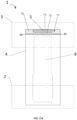
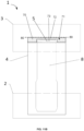
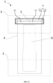
- Absorbent articles (1) herein are for personal hygiene, preferably a disposable pant, and comprise:
- a maximum distance (d2max) between a terminal edge (TE) of said waist barrier (4) corresponding to and/or forming a pocket opening and a closest terminal edge (TEa) of the absorbent core (8) is less than 20 mm, preferably less than 17 mm, even more preferably from 0mm to 15 mm.
- a capillary acceleration sheet is comprised along substantially an entire maximum distance (d2max), preferably along the entire said maximum distance, such that a fluid communication bridge is formed between at least the barrier (5) and the absorbent core (8).
- the capillary acceleration sheet may thus enable wicking of the body exudates therealong and towards the absorbent core that may then absorb the exudates even against gravity as the case may be depending on body position of the wearer.
- the capillary acceleration sheet is preferably a nonwoven, more preferably the nonwoven comprising, or consisting of, a carded air-through-bonded nonwoven or a spunbond nonwoven. Most preferred are nonwovens comprising an embossment pattern and/or apertures, hence in such embodiments the nonwoven comprises an embossment pattern and/or apertures.
- the capillary acceleration sheets herein may be comprised (or even formed entirely) of the topsheet of the absorbent article that is typically comprised by the insert, alternatively or in addition it may be an acquisition distribution layer that generally protracts so as to extend substantially along the entire distance d2max.
- an acquisition distribution layer that generally protracts so as to extend substantially along the entire distance d2max.
- the transversal waist barrier (5) comprises a film (typically joined to one or two nonwovens as described in more detail in embodiments herein).
- the film preferably extends over the majority of the waist barrier (5) or even has a total surface area that substantially corresponds to that of the barrier (5). It being understood that in embodiments herein where the barrier (5) is formed by folding of the insert the film surface area compared to the barrier (5) surface area may be greater than if the barrier (5) is formed by means of a patch in other embodiments herein; yet maintaining similar advantages being better leakage prevention especially at different body positions, sweat and the like that a wearer may subject the absorbent article to.
- the front and/or back panels (2, 3) preferably comprise a plurality of elastic strands, preferably sandwiched between two or more nonwoven layers as typically described herein, and wherein said front and/or back panels (2, 3) may comprise a tummy pause (TP) being free of said elastic strands or comprising elastic strands that have been rendered inelastic by deactivation (e.g. by deactivation/severing of the elastics via a knife or similar process); and wherein the barrier (5) overlaps said tummy pause (TP), preferably overlaps the entire width of said tummy pause (TP) along an axis parallel to the transversal centerline (x).
- TP tummy pause
- the opening is positioned closer to a transversal centerline (x) than the joined portions of the perimeter of the patch.
- the joined portion of the perimeter of the patch or discrete layer is joined by adhesive and/or mechanical bonding having a shape and/or pattern that is substantially C-shaped or U-Shaped, preferably such that at least one of the longest sides and at least two opposite portions of the shortest sides of said patch are joined and wherein at least one of the longest sides of said patch is un-joined or unattached to the absorbent insert (4).
- adhesive and/or mechanical bonding having a shape and/or pattern that is substantially C-shaped or U-Shaped, preferably such that at least one of the longest sides and at least two opposite portions of the shortest sides of said patch are joined and wherein at least one of the longest sides of said patch is un-joined or unattached to the absorbent insert (4).
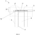
- Said patch or discrete layer (18) preferably comprising an elastic film or strands is preferably in the form of a rectangular patch.
- Said rectangular patch extends along the transversal edge of the absorbent insert (4) and partially along the longitudinal edges of the absorbent insert (4) as illustrated in FIG. 10 .
- said patch (18) covers the portion of the absorbent insert (4) proximal to the front and/or back transversal edge, preferably the portion of the absorbent insert (4) proximal to the back transversal edge.
- the discrete layer or patch (18) in embodiments herein may be bonded, meaning joined or attached or associated, to the absorbent insert (4) by at least one bonding means (19).
- Bonding means comprise and are not limited to for example adhesive bonding and/or mechanical bonding and/or ultrasonic bonding.
- the discrete layer or patch (18) can be joined to the absorbent insert (4) by two or more bonding means.
- the bonding means comprises here adhesive bonding (19a) in an area arranged along the transversal edge of the absorbent insert (4) and mechanical bonding (19b) in an area arranged along the longitudinal edge of the portion of the absorbent insert (4) proximal to the front and/or back transversal edge, preferably the back transversal edge.
- the bonding means comprise only adhesive bonding (19a) arranged along the transversal and longitudinal edges of the portion of the absorbent insert (4) proximal to the front and/or back transversal edge. Arranging the bonding means at the transversal and longitudinal edges of the absorbent insert (4) enables to have a proper waist transversal barrier (5) and contain any exudate within the absorbent insert (4).
- the opening formed by the unattached, or un-joined portion is positioned closer, or at equal distance for the edges of the shortest sides, to a transversal centerline (x) than the joined portions of the perimeter of the patch.
- the bonded portion is represented by reference (19) and the unattached portion is represented by reference (23).
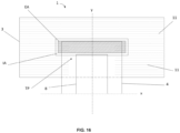
- the unattached portion (23) When looking at the absorbent article laid flat on a surface from above, the unattached portion (23) generally covers a portion of the absorbent insert (4), namely the portion proximal to the transversal edge of the absorbent insert (4). According to some embodiments, the unattached portion (23) can optionally further cover a portion of the absorbent core (8) as illustrated in FIG. 11B .
- the bonded or joined portion 19 can either cover a portion of the absorbent insert (4), namely the portion proximal to the transversal edge of the absorbent insert (4) only ( FIG. 10 ) or cover a portion of the absorbent insert (4), namely the portion proximal to the transversal edge of the absorbent insert (4) and a portion of the back panel (3) ( FIG.
- the patch or discrete layer 18 can be joined to the outer panel (3), namely to the inner nonwoven layer (9), and/or the patch or discrete layer 18 can be joined to absorbent insert (4).
- said barrier (5) comprises one or more of an elastic film and an elastic strand, and wherein the elastic film and/or strand(s) form an elastic area (EA) and wherein the elastic area is less than a patch area such that a substantially inelastic area (IA) is positioned outboard of the elastic area, preferably wherein the inelastic area comprises at least one of: an area free of elastic film and/or strand(s); and an area wherein the elastic film and/or strand(s) has been de-activated.
- Deactivation of elastic includes cutting or severing elastic for example using a knife roller combined to an anvil roller. Other methods of deactivation include and are not limited to melting, using heat and/or chemical agents, or any other means of providing stiffness e.g. glue in non-stretched state or addition of other stiffeners.
- At least a portion of the substantially inelastic area (IA) is joined to the absorbent insert (4) and/or panel(s) (2, 3).
- this allows for optimal anchoring.
- the un-joined portion of said perimeter comprises a further elastic material, preferably in the form of one or more elastic strands such as LYCRA ® .
- the elastic area (EA) comprises a plurality of wrinkles; and/or wherein the elastic area comprises a plurality of apertures.
- said least one nonwoven layer and elastic film and/or strands are joined by mechanical bonding, at a plurality of discrete bonding elements and wherein each said patch comprises a plurality of wrinkles having peaks and troughs formed on at least one of said nonwoven layer wherein said patch comprises an average of no more than two, preferably no more than one, wrinkles between two consecutive discrete bonding elements along a patch length extending substantially parallel to the transverse axis.
- the patch (18) comprises a wrinkle distribution of at least 1.1 wrinkles/mm, according to the method herein.
- the nonwovens may be deformed, and protrusions may be created where the apertures are formed.
- Such protrusions may extend outward from one surface of the laminate.
- the surface of the resulting laminate that includes the protrusions protruding therefrom may feel relatively rough and thus can detract from other desirable features of the elastic laminate, such as softness.
- the at least portion of said absorbent insert (4) proximal to the front and/or back transversal edges thereof comprises one or more folds forming the transversal waist barrier(s) (5), preferably wherein said fold is substantially U-shaped or C-shaped.
- fold of the absorbent insert allows to form a liquid impermeable barrier to exudates, and particularly the U-shape or C-Shape (vs other shapes) allows to form a maximised pocket for exudate collection with the minimum use of material.
- the folded portion of said absorbent insert (4) is joined to the body-facing surface of the topsheet (6) at a pair of oppositely disposed extremities of the absorbent insert (4) along a portion of the left and right longitudinal edges thereof, generally wherein said oppositely disposed extremities are connected by a fold of said folded portion of said absorbent insert (4), such that a pocket is formed that acts as a barrier to exudates in both the longitudinal direction (i.e. substantially parallel to the longitudinal axis y) and the transverse direction (i.e. substantially parallel to the transverse axis x).
- the said extremities of the absorbent insert (4) may be joined by adhesive and/or mechanical bonding such as ultrasonic bonding, thermal bonding, and/or pressure bonding and the like.
- the absorbent insert (4) comprises a substantially liquid permeable topsheet (6), a substantially liquid impermeable backsheet (7), and an absorbent core (8) sandwiched therebetween, preferably wherein the absorbent core (8) is positioned inboard of the perimeter of said absorbent insert (4) when viewed in a planar direction (as generally depicted and illustrated in the figures herein and that typically corresponds to a plane formed by the x and y axis described and illustrated herein) such that the one or more folds are substantially free of absorbent material.
- the inner and outer nonwoven layers (9, 10) may be the same or different meaning that they may have the same or different properties selected from basis weight (in gsm) and composition.
- both the inner and outer nonwoven layers (9, 10) each comprise a spunbond nonwoven, typically comprising monocomponent fibers of polypropylene, and each have a basis weight of from 10 g/m 2 (gsm) to 30 g/m 2 (gsm), preferably from 12 g/m 2 (gsm) to 25 g/m 2 .
- the outer nonwoven layer (10) may have a basis weight that is higher than the inner nonwoven layer (9).
- barrier embodiments herein especially when the outer nonwoven layer is folded and/or extends over the absorbent insert; and/or when the transversal barrier is elasticised
- such arrangement provides for added mechanical integrity desirable for resistance to tear on elastification and/or added softness for the wearer on the front and/or back waist regions up to said barrier location.
- transversal waist barrier(s) In addition or alternatively, more than 50%, preferably more than 60%, even more preferably from 65% to 95%, of a total transversal length (generally substantially parallel to the transversal axis x) of the transversal waist barrier(s) (5) overlaps the deactivated region of the panel(s) (2, 3). Especially when the transversal waist barrier(s) is elastic, this arrangement may advantageously not only improve core integrity but further avoid excessive tension build-up.
- the transversal waist barrier(s) (5) is elastic, preferably comprising an elastic material selected from the group consisting of an elastic film and one or more elastic strands.
- an elastic material selected from the group consisting of an elastic film and one or more elastic strands.
- the elastic strands in any of the embodiments herein may be strand-coated with adhesive prior to joining to one or more layers such as the inner and outer nonwoven layers (9, 10) to form elastic panels (2, 3) and/or the backsheet (7), outer cover (7'), and/or outer nonwoven layer (10) to form the elastic transversal waist barrier(s) (5).
- adhesive in the form of a plurality of stripes is applied such as by slot coating.
- flat elastic When one or more, preferably only one, flat elastic is used it is preferably positioned adjacent to an apex of the transversal waist barrier(s) (5) that may be closest to a transversal edge of the absorbent insert (4) and further round elastic(s) positioned further from said apex compared to the flat elastic(s).
- this allows for the flat elastic to be positioned at the closest contact position to the wearer with other elastics being inboard (or further away) therefrom hence contributing to the desired tensile strength yet permitting to lower the overall density/dtex of the flat elastic and hence also cost, with limited impact on performance.
- elastic strands When elastic strands are used, they may have a dtex in the range of from 350 to 1100, preferably from 400 to 1000, even more preferably from 450 to 900.
- the elastic strands of said panel(s) (2, 3) When elastic strands are used in all of the front and/or back panels (2, 3) and the transversal waist barrier(s) (5), the elastic strands of said panel(s) (2, 3) have a dtex that is equal to or greater than, preferably greater than, that of the elastic strand(s) of said transversal waist barrier(s) (5).
- the elastic strand(s) of said transversal waist barrier(s) (5) have a dtex that is from 40% to 85%, preferably from 45% to 75%, even more preferably from 50% to 70%, of the dtex of the elastic strands of said panel(s) (2, 3).
- this allows said barrier(s) to stand up and provide a gasketing effect close to the skin of the wearer without flattening or adding excessive resistance to stretch that would otherwise impact fit and comfort.
- the tension differential that results entails that a lower tension in said barrier(s) compared to the belt(s) is generated to a degree that upon stretching of the belt(s) said barrier(s) stand-up away from said belt(s).
- the front and back panels (2, 3) may each be divided into multiple zones spanning in the transverse direction and defined by its location from the distal edge to the proximal edge relative to the percentage of the seam length wherein the distal edge is considered 0% and the proximal edge is considered 100%.
- the multiple zones may be configured to provide different tensile stress, or different functions to the front and back panels (2, 3), respectively.
- the outer nonwoven layer (10) is wider than the inner nonwoven layer (9) (generally in a direction substantially parallel to the longitudinal axis y) and is folded over said inner nonwoven layer (9) such that it overlaps the portion of said absorbent insert (4) proximal to the front and/or back transversal edges and generally over a fold length (LF), preferably such that said outer nonwoven layer (10) overlaps both a portion of the backsheet (7) and a portion of the topsheet (6) that remains exposed from said one or more transversal waist barrier(s) (5) such to form a flange (F L ).
- this allows to cover the backsheet with nonwoven so that the backsheet does not come into contact with the skin of a wearer which could otherwise result in skin irritations and/or less comfort.
- the absorbent insert (4) may comprise a topsheet selected from an embossed nonwoven and/or a carded air-through-bonded nonwoven.
- the embossed nonwoven may comprise a spunbond nonwoven.
- the topographical surface of such particular nonwoven selection allows for the formation of peaks and slumps that acts to not only slow down the movement of liquid stool towards the transversal edges but further allows for containment ridges in areas overlapping said barrier(s) (5).
- the thickness of the absorbent insert (4) in an overlap area of said waist barrier (5) is less than the remaining thickness of said insert (4) (e.g. in areas other than the overlap area); and/or wherein the amount of absorbent material in in an overlap area of said waist barrier (5) is less (preferably at least 5%wt less, preferably at least 10%wt less, even more preferably at least 15%wt less, even more preferably at least 20%wt less) than the amount of absorbent material in other areas of said insert.
- said overlap area further overlapping with the front and/or back panels respectively.
- this allows for a larger pocket for exudate collection that synergistically cooperates with the overlapping front and/or back belts.
- steps may be sequential in the order listed here-above or may be sequential but with the steps of joining said patch and joining said inserts being carried out substantially concurrently.
- the bonding means comprise applying a pattern of adhesive onto a discrete layer or patch (18) and/or applying a pattern of adhesive onto a portion of the absorbent insert (4) proximal to the front and/or back transversal edge said pattern of adhesive extending all along the transversal edges and partially along the longitudinal edges of the patch and/or absorbent insert (4) and applying said patch or discrete layer onto the top surface of the absorbent insert (4) at a portion of the absorbent insert being proximal to the front and/or back transversal edge to form transversal waist barrier(s) (5) or wherein the bonding means comprise mechanical bonding preferably ultrasonic bonding
- the method further comprises the steps of arranging an elastic material (12) over said discrete layer or patch (18) prior to step of folding an outer nonwoven layer (10) of the front and/or back panels (2, 3) over the folded absorbent insert (4) and patch or (18).
- the method further comprises the steps of folding an outer nonwoven layer (10) of the front and/or back panels (2, 3) over the absorbent insert (4) and discrete layer and joining said folded outer nonwoven layer (10) directly or indirectly to the absorbent insert (4) partially covered by the discrete layer.
- front and back panels herein are made from continuous webs that are subsequently severed into discrete front and back panels typically after the step of joining the absorbent insert 4 to said front and back panels 2, 3.
- the method further comprises the steps of folding an outer nonwoven layer 10 of the front and/or back panels 2, 3 over the folded absorbent insert 4 and/or an inner nonwoven layer 9 and joining said folded outer nonwoven layer 10 directly or indirectly to the folded absorbent insert 4.
- this allows to prevent irritation or discomfort to the wearer as explained hereinabove whilst avoiding the use of added components/materials/elements whilst maintaining a simple and cost-effective production process.
- the method further comprises the step of arranging an elastic material 12 over the folded portion of the folded absorbent insert 4 prior to step of folding an outer nonwoven layer 10 of the front and/or back panels 2, 3 over the folded absorbent insert 4.
- the method further comprises the step of intermittently applying adhesive onto said portion of the absorbent insert proximal to the front and/or back transversal edges.
- the adhesive is applied in joining zones or bonding zones.
- the joining or bonding zones comprises at least one area where the adhesive or mechanical bonding mean is applied.
- the pattern 71 of adhesive comprises the two portions or two areas of adhesive 70, meaning two joining zones, as described hereabove, meaning the area 70 at the transversal extremities of the transversal edge, or in other words, the corners of the absorbent insert 4, or also the portions where the back transversal edge and longitudinal edges of the absorbent insert 4 connect as illustrated in FIG. 11A .
- the pattern 71 of adhesive further comprises a further area 72 of adhesive extending transversally connecting the two areas 70 and an area free of adhesive 73, said area free of adhesive 73 is arranged between the transversal edge of the absorbent insert 4 and the further area 72 of adhesive with respect to the longitudinal direction (y) and arranged between the two areas 70 at the corners with respect to the transversal direction (x).
- the pattern 71 of adhesive comprise a U-shaped or C-shaped pattern with two areas 70 corresponding to the upper branches of the U, said areas 70 being connected by a further area 72 corresponding to the lower branch of the U.
- the pattern 71 of adhesive comprise a H-shaped pattern with two areas 70 corresponding to the side branches of the H, said areas 70 being connected by a further area 72 corresponding to the middle branch of the H.
- the pattern of adhesive can comprise two areas 70 at the corners and a further area 72 of adhesive which extend only partially along the transversal axis (x) and does not connect the two areas 70 while still defining an area free of adhesive 73 as described above.
- the further area 72 can comprise a gap free of adhesive.
- the pattern 71 of adhesive can comprise two areas 70 that are L shaped in facing relationship or in mirror relationship, said L-shaped areas being arranged at each corner.
- a transversal waist barrier 5 is defined with the area free of adhesive 73 not being joined to the absorbent insert 4 and therefore standing upright.
- said barrier(s) 5 herein form an opening, typically about a terminal edge of the folded outer nonwoven layer, of an exudate containing pocket wherein substantially the entire surface of the pocket being congruent with a topsheet 6 of the absorbent insert 4 comprises a liquid impermeable layer preferably being a film, more preferably an elastic film (generally according to the embodiments described herein).
- the angle defined by the fold and the waist barrier is more acute and can provide a transversal waist barrier 5 with more resistance to exudates.
- the method can comprise a mechanical bonding step where the portion of the absorbent insert 4 proximal to the back transversal edge is folded thereof onto itself and then mechanically bonded.
- the method comprises a step where the portion of the absorbent insert 4 proximal to the back transversal edge is glued to the absorbent insert 4 and/or a step where the portion of the absorbent insert 4 proximal to the back transversal edge is mechanically bonded to the absorbent insert 4.
- adhesive is intermittently applied to the portion of the absorbent insert 4 proximal to the back transversal edge, then said portion is folded thereof onto itself, then the folded portion is mechanically bonded, e.g. ultrasonic welding, to further secure the transversal waist barrier 5.
- the present disclosure pertains to a method for the manufacture of an absorbent article (1) comprising the steps of:
- a patch of liquid impermeable film and/or applying a pattern of adhesive onto a portion of the absorbent insert (4) proximal to the front and/or back transversal edge said pattern of adhesive extending all along the transversal edges and partially along the longitudinal edges of the patch and/or absorbent insert (4); applying said discrete layer or patch (18) preferably comprising liquid impermeable film onto the top surface of the absorbent insert (4) at a portion of the absorbent insert being proximal to the front and/or back transversal edge to form transversal waist barrier(s) (5) and joining said front and back panels (2, 3) together along a pair of oppositely disposed side seams.
- this embodiment further comprises the step of arranging an elastic material (12) over said discrete layer or patch preferably comprising liquid impermeable film prior to step of folding an outer nonwoven layer (10) of the front and/or back panels (2, 3) over the folded absorbent insert (4) and patch.
- Said discrete layer or patch (18) preferably comprising liquid impermeable film is preferably in the form of a rectangular patch.
- Said rectangular patch extends along the transversal edge of the absorbent insert (4) and partially along the longitudinal edges of the absorbent insert (4) as illustrated in FIG. 10 .
- said patch (18) covers the portion of the absorbent insert (4) proximal to the front and/or back transversal edge, preferably the portion of the absorbent insert (4) proximal to the back transversal edge.
- the discrete layer or patch (18) preferably comprising liquid impermeable film is bonded, meaning joined or associated, to the absorbent insert (4) by at least one bonding means (19).
- Bonding means comprise and are not limited to for example adhesive bonding and/or mechanical bonding and/or ultrasonic bonding.
- the discrete layer or patch (18) can be joined to the absorbent insert (4) two or more bonding means.
- the bonding means comprises here adhesive bonding (19a) in an area arranged along the transversal edge of the absorbent insert (4) and mechanical bonding (19b) in an area arranged along the longitudinal edge of the portion of the absorbent insert (4) proximal to the front and/or back transversal edge, preferably the back transversal edge.
- the bonding means comprise only adhesive bonding (19a) arranged along the transversal and longitudinal edges of the portion of the absorbent insert (4) proximal to the front and/or back transversal edge. Arranging the bonding means at the transversal and longitudinal edges of the absorbent insert (4) enables to have a proper waist transversal barrier (5) and contain any exudate within the absorbent insert (4).
- the total surface area of the discrete layer or patch (18) preferably comprising liquid impermeable film is greater than the surface area of the bonding means (19), meaning that at least a portion of the total surface area of the discrete layer or patch (18) preferably comprising liquid impermeable film is not joined to the absorbent insert.
- the bonding means extend over a surface area of the discrete layer or patch (18) preferably comprising liquid impermeable film that is lesser than the total surface area of the discrete layer or patch (18) preferably comprising liquid impermeable film.
- the adhesive (19a) can be applied in a pattern, such as in a U-shaped or C-shaped pattern extending along the transversal and longitudinal edges of the portion of the absorbent insert (4) proximal to the front and/or back transversal edge.
- a pattern can optionally comprise notches 19c to save on raw material.
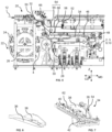
- FIG. 5 illustrates one possible embodiment for an apparatus 20 for manufacturing such absorbent articles 1.
- the apparatus 20 extends in a machine direction MD, a cross-direction CD and a vertical direction Z.
- the machine direction MD corresponds to the direction of travel of the webs, elastic materials or any components of the absorbent articles 1 being manufactured
- the cross-direction CD is a direction perpendicular to the machine direction MD
- the vertical direction Z correspond to the height and is also a direction perpendicular to both the machine direction MD and the cross-direction CD.
- the machine direction MD is the flow direction of an absorbent article and its components being assembled in the process line, e.g. the machine direction MD is the direction in which the absorbent insert 4 is conveyed.
- upstream and "downstream” as used herein are with respect to the machine direction MD.
- coordinate system using longitudinal and transversal axis pertains to the absorbent article 1 alone e.g. when laid flat on a surface
- coordinate system using machine, cross and vertical directions pertains to the apparatus for manufacturing absorbent article 1 with the absorbent articles 1 and their components being conveyed.
- an absorbent insert 4 is provided.
- the absorbent insert 4 assembled beforehand, is transferred by a transfer device 22, a unit 22 comprising a plurality of transfer heads 24 arranged on a support wheel 26 with both the support wheel 26 and the transfer heads 24 being configured to respectively rotate around a respective axis.
- the transfer device 22 is an apparatus that is configured to turn and repitch the discrete absorbent inserts 4, turn the discrete absorbent inserts 4, or merely transfer the discrete absorbent inserts 4 between a pick-up location and a drop-off location.
- the transfer device 22, as illustrated in FIG. 5 comprises a frame 26, here a support wheel 26, defining a rotation axis and a plurality of transfer heads 24 associated to said frame 26.
- the transfer heads 24 are configured to circumnavigate about the rotation axis in an orbit. As illustrated in FIG. 5 , the support wheel 26 rotates around an axis parallel to the cross-direction CD and the transfer heads 24 circumnavigate about this rotation axis in an orbit. The orbit passes through the pick-up location and the drop-off location.
- the transfer device 22 turns the discrete absorbent inserts 4 in any suitable angle. For example, as illustrated in FIG. 5 , the transfer device 22 turns the discrete absorbent inserts 4 about 90 degrees. The discrete absorbent inserts 4 are turned by the transfer heads 24 turning.
- a transfer head 24 may pick up a discrete absorbent insert 4 in a pick-up location, turn 90 degrees about an axis perpendicular to the rotation axis of the frame, e.g. about the vertical direction Z, drop off the discrete absorbent insert 4 in a drop-off location, and the turn back to its original position (either in the same direction or an opposite direction) before orbiting back through the pick-up location.
- the transfer device 22 transfers an absorbent insert 4 extending in the machine direction (MD) and rotates it so that said absorbent insert 4 extends in the cross direction (CD).
- the first conveyor belt 28 and/or rotating drum 30 comprises vacuum holes on its outer surface, meaning a foraminous outer surface, and the absorbent insert 4 is deposited onto said outer surface.
- the absorbent insert 4 is maintained on the foraminous drum 30 and/or foraminous first conveyor belt 28 by the negative air-pressure generated by the suction. As illustrated in FIG. 5 , the absorbent insert 4 is first deposited onto the rotating drum 30 and then transferred to the first conveyor belt 28, the absorbent insert 4 is then conveyed by the first conveyor belt 28 in the machine direction MD.
- adhesive is applied intermittently on at least one transversal edges, namely the adhesive is applied intermittently on a portion of said absorbent insert 4 proximal to the front and/or back transversal edges, meaning on the portion described hereabove to be folded.
- the adhesive is applied intermittently on at least one edge arranged at one end of the absorbent insert 4 with respect to the cross-direction CD as illustrated in figure 8 .
- the adhesive can be applied intermittently on one portion of said absorbent insert 4 proximal to the back transversal edges.
- the adhesive can be applied intermittently to one portion of said absorbent insert 4 proximal to the front transversal edges.
- the adhesive can be applied intermittently to both portions of said absorbent insert 4 proximal to the front and back transversal edges.
- the adhesive is applied intermittently such that the central area of said portion(s) proximal to the transversal edge(s) is not glued.
- the adhesive is applied on both portions 70 arranged at the corners of a transversal edge, but not in between said corners 70 as illustrated in FIG.4 .
- the adhesive is applied in the portion 70 located at the corner of the back transversal edge but is not applied on the portion where the absorbent core 8 extends, meaning when the back transversal edge and the absorbent core are transposed on a same machine direction axis, the adhesive applied is present at the corners but not where the absorbent core 8 extends.
- the adhesive is applied intermittently on one transversal edge only, preferably the back transversal edge.
- the adhesive is applied intermittently on both transversal edges.
- the adhesive can also be applied continuously in an adhesive pattern 71 as described above, for example in a U-shaped or a C-shaped or a H-shaped pattern.
- the adhesive is applied by a glue dispensing device 32.
- a glue dispensing device 32 Such application of adhesive may be by various processes such as slot coating, spray coating and other topical applications using a pneumatic, piezo or electromagnetic actuator.
- the glue dispensing device 32 comprises at least one nozzle, each nozzle, for instance, may comprise a slot coating device or several exit ports and an adhesive flow control device such as electromagnetic valve, e.g. a solenoid valve.
- the absorbent insert 4 is then conveyed, or transported, by the first conveyor belt 28 to a folding unit 34.
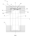
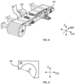
- the folding unit 34 comprises a folding blade 36 that is curved ( FIG. 6 , 9 ) and that can be associated with a support plate 38 as illustrated in FIG. 6 .
- the folding blade 36, or curved blade 36 comprises a blade with a curvature said curvature spanning over an angle from 0° to at least 200°.
- the curved blade comprises a concave portion, said concave portion varying along the machine direction and extending over an angle A° of at least 180°, preferably at least 250°, more preferably at least 300°, meaning angle A° is preferably a reflex angle as illustrated in FIG. 9 .
- the folding blade 36 comprises a curve blade 36, said curved blade 36 defines an angle A° that evolves along the machine direction MD, meaning that for a given point in the machine direction MD, the folding blade 36 extends in the vertical and cross directions Z,CD as illustrated in FIG. 9 , the two extremities of said blade 36 defining an angle A°, or folding angle A°, since the folding wall, meaning the wall used for folding the absorbent insert 4, of the blade is curved.
- the angle A° defined by the two extremities of the blade 36 is small, e.g. between 0° and 10°.
- the angle A° increases along the machine direction MD and is greater than 180° at the downstream portion of the folding blade 36.
- the support plate 38 is fixed, or removably associated to the folding blade 36. Having a blade 36 with a folding angle A° of 180° is sufficient to fold the absorbent insert 4 onto itself but it can lead to having wrinkles or a gap in the fold. Having a blade 36 with a folding angle A° of 250° or more enables to have a smoother fold and reduces the risks of wrinkles or a gap in the fold.
- the apparatus 20 can comprise a depositing unit, for example a liquid impermeable film layer depositing unit, or a patch depositing unit or a patch applying unit where a plurality of liquid retarding layers in the form of a patch or a discrete layer preferably of liquid impermeable film applied in the form of a patch is joined to said absorbent insert (4) via suitable bonding techniques such as adhesive and/or mechanical bonding as described hereabove.
- the apparatus comprises a bonding unit to join the patch 18 to the absorbent insert (4) and/or to the inner nonwoven layer (9), more generally to the back and/or front panel (3), to form a transversal barrier.
- the patch depositing unit and the bonding unit as sequential, in the sense that if the bonding means correspond to adhesive bonding, either the absorbent insert and/or the patch (18) pass first through the bonding unit first and adhesive is applied on the absorbent insert and/or the patch (18) and then through the patch depositing unit, alternatively, if the bonding means correspond to mechanical bonding the absorbent insert (4) passes through the patch depositing unit first and then through the bonding unit.
- the bonding means correspond to adhesive bonding
- the absorbent insert (4) passes through the patch depositing unit first and then through the bonding unit.
- the folding unit 34 can further comprise a pressing blade 40 arranged at a distance d from the curved blade 36 with respect to the cross-direction CD and/or vertical direction Z. In other words, there is a gap between the curved blade 36 and the pressing blade 40 in the cross-direction CD and/or vertical direction Z.
- the pressing blade 40 presses vertically against the absorbent insert 4 and maintain said absorbent insert 4 in place, at least vertically.
- the combination of the curved blade 36 folding the portion of the absorbent insert 4 proximal to the front and/or back transversal edge, and the pressing blade 40 pushing the absorbent insert 4 at least vertically, ensures a proper folding of the portion of the absorbent insert 4 proximal to the front and/or back transversal edges thereof onto itself, in order words a proper folding of the portion of the absorbent insert 4 proximal to the front and/or back transversal edge to form a transversal barrier 5 as described herein.
- the folding blade 36 deviates the portion of the absorbent insert 4 proximal to the front and/or back transversal edge in the cross direction CD and in the vertical direction Z and the pressing blade 40 deviates a portion of the absorbent insert 4, which is more distal to the transversal edge than said portion of the absorbent insert 4 proximal to the transversal edge e.g. in between said portion of the absorbent insert 4 proximal to the front and/or back transversal edge and the center of absorbent core 8, in the vertical direction Z.
- the pressing blade 40 at least maintains the absorbent insert 4 in place while the folding blade 36 is folding the portion of the absorbent insert 4 proximal to the transversal edge.
- the folding blade 36 alone can suffice to fold the portion of the absorbent insert 4 proximal to the front and/or back transversal edge, and adding a pressing blade 40 further improves the folding.
- the folding blade 36 ensures a folding preferably in the shape of a substantially U-fold, to form transversal waist barrier(s) 5. In the embodiment described above where adhesive is applied intermittently at the corners 70, then only the corners 70 of the portion of the absorbent insert 4 proximal to the front and/or back transversal edges are folded and glued thereof onto itself.
- the pressing blade 40 is preferably shorter in length, with respect to the machine direction MD, than the folding blade 36 so that when the curved blade 36 is folding the portion of the absorbent insert 4 proximal to the front and/or back transversal edge, namely once said portion has been folded by an angle of more than 180°, it folds thereof onto itself, meaning onto the upper surface of the absorbent insert 4, i.e. the topsheet 6.
- the pressing blade 40 can be a flat plate as illustrated in FIG. 7 , or it can be a rod or a cylindric tube.
- the pressing blade 40 can comprise an anti-adhesive coating to ensure that the absorbent insert 4 when being folded does not adhere onto the pressing blade 40.
- the pressing blade 40 can also be connected to an air-compressor and comprise air-vents or holes on its surface to blow out pressurized air to ensure that the absorbent insert 4 when being folded does not adhere onto the pressing blade 40.
- the partially folded absorbent insert 4 may then be guided toward a rotating drum 48 where it is deposited onto two webs corresponding to front and back panels 2,3 comprising the inner nonwoven layer 9 and outer nonwoven layer 10 as described hereabove.
- the front and back panels 2,3 are assembled beforehand with the lamination of inner and outer nonwoven layers 9,10 and elastic material 11 and by intermittently severing the elastic material 11.
- the folding apparatus 64 can further comprise a railing 68 oriented diagonally with respect to the cross-direction CD toward the center of absorbent insert 4 to guide and facilitate the folding of the non-deviated portion of the outer nonwoven layer 10, i.e. the transversal edge of the front and/or back panel 2,3 onto the absorbent insert 4, namely onto the transversal barrier 5, backsheet 7 and/or outer cover 7'.
- a railing 68 oriented diagonally with respect to the cross-direction CD toward the center of absorbent insert 4 to guide and facilitate the folding of the non-deviated portion of the outer nonwoven layer 10, i.e. the transversal edge of the front and/or back panel 2,3 onto the absorbent insert 4, namely onto the transversal barrier 5, backsheet 7 and/or outer cover 7'.
- the belt meaning the front and back panels 2,3 may then be cut in the cross-direction CD into individual pieces, each individual piece comprising an absorbent insert 4 with a front and back panel 2,3. Each individual piece is then folded to bring the front and back panels 2,3 in proximity of one another and then associated in side seams to form an individual absorbent article 1 with a transversal barrier 5.
- the front and back panels 2,3 are joined, or associated, by bonding said panels 2,3 together at a bonding unit.
- the bonding unit can be selected from and not limited to an adhesive dispensing device, an ultrasonic device or a welding device.
- the front and back panel 2,3 can be joined first and then cut in the cross direction into individual pieces.
- the folding unit 34 comprises a support device 54 to carry the folding blade 36 and/or support plate 38 and/or pressing blade 40.
- the support device 54 can comprise means to move the folding blade 36 and/or support plate 38 and/or pressing blade 40, e.g. a system with rails and an actuator to slide the folding blade 36 and/or support plate 38 and/or pressing blade 40 in the cross-direction CD and/or vertical direction Z.
- the support device 54 can comprise means to remove the folding blade 36 and/or support plate 38 and/or pressing blade 40, e.g. a plurality or screws, bolts, threaded rods and nuts, etc. so that the folding blade 36 and/or support plate 38 and/or pressing blade 40 can be removed entirely.
- Such system enables to easily change the production from an absorbent article 1 with transversal barrier(s) 5 to a standard product without transversal barrier(s) 5.
- the adhesive dispensing device and elastic strand(s) 12 guiding device are turned off for standard products.
- the adhesive dispensing device 32 can continuously apply adhesive.
- the folding blade 36 comprises an extension 56 as illustrated in FIG. 9 where the extension 56 extends beyond the curvature of the blade 36 to ensure that the transversal edge is well folded thereof onto itself.
- the first conveyor belt 28 comprises a foraminous portion arranged at the central portion 60 of the first conveyor belt 28 with respect to the cross-direction CD as illustrated in FIG. 8 .
- Such arrangement ensure that the absorbent insert 4 is well fastened in the central portion 60, meaning in the crotch region of the absorbent insert 4, and is loosely secured at the at least one portion of the absorbent insert 4 proximal to the transversal edge.
- Such arrangement ensures that the folding blade 36 does not meet any resistance and that the portion of the absorbent insert 4 proximal to the transversal edge can be folded more easily. In other words, the vacuum should not impede the folding at the one or both cross direction extremities.
- the first conveyor belt 28 can also comprise a portion blowing out air at one cross direction extremity, the extremity proximal to the folding unit 34, to favor the lifting and thus folding of the portion of said absorbent insert 4 proximal to the front and/or back transversal edge.
- the folding unit 34 comprises an adjustable mechanism 62 to adjust the distance between the pressing blade 40 and the folding blade 36.
- adjustable mechanism comprises for example a plate with notches and screws enabling the sliding of the plate between the notches and adapt the distance with respect to the cross direction and/or vertical direction.
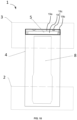
- the absorbent insert 4 associated with, or deposited onto, the front and back panels 2,3 are conveyed from the rotating drum 48 to the elastic strand(s) 12 application unit by a second conveying unit 58, e.g. a second conveyor belt 58.
- the first conveyor belt 28 and the second conveyor belt 58 can transport the absorbent inserts 4 at the same speed to avoid the formation of wrinkles or creases.
- the first conveyor belt 28 and the transfer device 22 can also rotate at matching speed to avoid the formation of wrinkles or creases.
- the two webs of front and back panels can be conveyed at same speed or at different speed. If the two webs of front and back panels are conveyed at same speed, front and back panels will have the same lengths with respect to the transversal direction or machine direction and the side seams will be arranged at the sides of the wearer. If the two webs of front and back panels are conveyed at different speed, e.g. the web of back panel is conveyed faster than the web of front panel then the back panel will be longer than the front panel and the side seams will be more toward the front at the sides of the wearer.
- the folding unit 34 comprises two folding blades 36 each with eventually with a pressing blade 40, one arranged at each transversal edge of the absorbent insert 4, meaning one arranged at each end of the first conveyor belt 28 with respect to the cross-direction CD.
- the two folding blades 36 are substantially identical in dimensions and shape and are preferably arranged in facing relationship or in mirror relationship, meaning at the same area with respect to the machine direction MD.
- Such arrangement enables to balance the force exerted onto the absorbent insert 4 and optionally to remove the pressing blade(s) 40.
- the rest of the process is arranged accordingly, namely an elastic thread(s) 12 is arranged between the absorbent insert 4 and the front panel which is folded onto the elastic thread(s) 12.
- Such arrangement also enables to have a transversal waist barrier 5 in the front and in the back.
- the elastic material 11 sandwiched between the inner nonwoven layer 9 and the outer nonwoven layer 10 and the elastics strands 12 are different.
- the elastics 11,12 can differ in cross-sectional shapes, e.g. round or flat, in dtex, in composition and/or in color.
- said elastic material 11 and elastic strands 12 can the same material.
- the method and process can comprise the placing of leg cuffs and leg elastics, wetness indicators, etc.
- the different embodiments can also be combined.
- the embodiments where the transversal waist barrier(s) (5) is a patch or a folded portion of the absorbent insert (4) are not mutually excluding one another and they can be combined and features described in relation to one can be applied to the other.
- the wrinkle distribution herein is determined by the following method.
- the number of wrinkles is counted over a length of 10mm along the panel length (L) with the laminate in relaxed state (i.e. without applying an extension force between ends thereof, preferably taken at its "unused” state wherein "unused” herein means without the panel ever having been previously stretched since manufacture).
- the total number of wrinkles is then divided by 10 in order to provide the number of wrinkles per unit length.
- a total of 4 random locations within the elastic region (20) of the laminate may be measured accordingly and an average is calculated for each sample.
- the 10mm length is typically taken from a starting position that encompasses at least one full wrinkle (i.e. a complete wrinkle comprising a peak positioned between two consecutive troughs) and by doing so if at the opposite extremity of the 10mm length only a partial wrinkle (i.e. not a complete wrinkle comprising a peak positioned between two consecutive troughs, e.g. the 10mm end at a position corresponding to the peak of a wrinkle) is formed, this is not counted as a wrinkle within the present method.
- a partial wrinkle i.e. not a complete wrinkle comprising a peak positioned between two consecutive troughs, e.g. the 10mm end at a position corresponding to the peak of a wrinkle
- the above procedure is typically repeated for at least 4 samples of side panels and an average is calculated to provide the wrinkle distribution in wrinkles/mm as referred to herein.
- the Hysteresis Test can be used to various specified strain values.
- the Hysteresis Test utilizes a commercial tensile tester (e.g., from Instron Engineering Corp. (Canton, MA), SINTECH-MTS Systems Corporation (Eden Prairie, MN) or equivalent) interfaced with a computer.
- the computer is used to control the test speed and other test parameters and for collecting, calculating, and reporting the data.
- the tests are performed under laboratory conditions of 23 °C + 2°C and relative humidity of 50% + 2%.
- the specimens are conditioned for 24 hours prior to testing.
- the specimen is cut with a dimension of 10 mm in the intended stretch direction of the ear X 25.4 mm in the direction perpendicular to the intended stretch direction of the ear.
- a specimen is collected from either an inelastic region or from an elastic region.
- a computer data system records the force exerted on the sample during the test as a function of applied strain. From the resulting data generated, the following quantities are reported:
- the testing is repeated for six separate samples and the average and standard deviation reported.
- the moisture vapour (or vapor) permeability of a layer, or a composite laminated structure comprising a plurality of such layers is measured via the Water Vapour Transmission Rate (WVTR) at 30°C and 15% relative humidity according to the ISO 15106-1:2003 test method.
- WVTR Water Vapour Transmission Rate
- a Lyssy L80-5000 Water Vapor Permeation Analyser manufactured and sold by Systech Instruments Ltd and Illinois Instruments Inc. may be used.
- test samples are clamped to a tensile testing machine (such as an Instron 5543 or similar) and stretched at a cross-head speed of 300mm/min at the desired elongation (such as 0%; 20%; 40%; 60%; 80%; 100%; 120%; and 140% elongations).
- a test sample having a length of 40mm at 0% elongation is stretched to 48mm length at 20% elongation; 56mm length at 40% elongation; 64mm length at 60% elongation; 72mm length at 80% elongation; 80mm length at 100% elongation; 88mm length at 120% elongation; 96mm length at 140% elongation; and so on.
- the stretched test sample is then affixed to a self-adhesive sample card with an open area of 2.5cm2 which is to be covered by the specimen that is subsequently tested according to the WVTR method described in the above referenced standard.
- the sample card with stretched film sample is inserted into the test chamber of the Water Vapor Permeation Analyser.
- the lower test chamber has a saturated atmosphere maintained by a small water reservoir, while the upper chamber contains a sensitive, fast-responding relative humidity sensor.
- the upper chamber is first dried to a defined humidity level using dry air.
- the Seepage is defined as a leakage fraction of artificial liquid exudates (saline solution composition described in the following sections for use in the test procedure herein) that is expelled beyond and/or through the transversal waist barrier or pocket of the absorbent article.
- An absorbent article in the pant form i.e. the type of absorbent articles to which the present invention generally refers
- the width of the back elastic belt is measured by applying a weight of 1.000 kg across the side edges formed along the previously cut open side seams of the back elastic belt.
- One of the side edges of the back elastic belt is clamped centered on the last centimeter of the side edge of the back elastic belt in a flat jaw 5 cm wide fixture with 1cm clamping depth. It is hung vertically and a 1.000kg weight is attached to an identical clamp that is provided the same manner and position on the other side edge of the back elastic belt and the weight is slowly released manually.
- the back elastic belt width is measured from clamp to clamp and 2cm are added to the result. The result is rounded to the next cm.
- the width of the front elastic belt is determined in the same manner as the width of the back elastic belt.
- the same procedure as described above is used for measuring the length of the absorbent article by applying a weight of 0.300kg.
- the absorbent article is clamped across the longitudinal centerline of the absorbent article on the last centimeter of the back waist edge in a flat jaw 15 cm wide fixture (centered on the longitudinal centerline) with 1cm clamping depth. It is hung vertically and a 0.300kg weight is attached to an identical clamp that is provided the same manner and position on the front waist edge of the absorbent article and the weight is slowly released manually.
- the absorbent article length is then measured after 30 second from clamp to clamp and 2cm are added to the result. The result is rounded to the next cm.
- An inclined surface is made from acrylic plates so that a laying face corresponding to the face onto which an article is to be placed, is at an angle of 25° from a horizontal plane (e.g. a table onto which the inclined surface is placed).
- the laying face should be sized so as to accommodate thereon an absorbent article in laid-flat sate (i.e. stretched/extended to the above explained measured width and length dimensions).
- the whole laying face of the plate may be conveniently coated with hook material to nicely hold the absorbent article in laid-flat sate by interaction of said hooks with nonwoven layers of the article or alternatively tapes may be used to hold the article in position.
- a line 5mm above the terminal transversal edge (TT) of the pocket and running parallel therewith should correspond to an upper edge of a filter paper when placed according to the below explained procedure.
- Liquid that leaks through the barrier is collected by the filter paper.
- the filter paper is then weighed and the original (dry) weight is subtracted. This calculation a rewet value for the filter paper in grams (g).
- the Seepage Index % rewet value g / total saline solution added g * 100
- Saline solution preparation 9g of NaCl are dissolved in 1000ml of H 2 O.
- the present examples aim at comparing commercially available pants with waist barrier (comparative examples A and B) with absorbent articles according to the disclosure.
- Comparative Example A Commercially available baby diaper pant sold under the brand Pampers baby-dry TM with stop & protect barrier, sizes 4, 5 and 6 respectively. Manufactured by The Procter & Gamble Company with its headquarters in Cincinnati (OH), USA. The stop & protect barrier comprising two layers of nonwoven formed by folding of a nonwoven belt. Tested products are in the form of pants and as commercially available second half of 2022. Pampers absorbent articles have an absorbent core having no airfelt (i.e. no cellulose fibers, instead all absorbent material are superabsorbent polymer particles).
- Example 1 A disposable absorbent article in the form of a pant, sizes 4, 5 and 6 respectively, according to the appended Claims.
- the absorbent core comprising about 25%wt of cellulose fibers and about 75%wt SAP.
- the plurality of liquid retarding layers of the waist barrier comprising a nonwoven (hydrophobic SMS, 12gsm) and a film (Polyethylene film, 14 gsm). The film extending over the majority of the barrier.
- Example 2 A disposable absorbent article in the form of a pant, sizes 4, 5 and 6 respectively, according to the appended Claims.
- the absorbent core comprising about 20%wt of cellulose fibers and about 80%wt SAP.
- the plurality of liquid retarding layers of the waist barrier comprising a nonwoven (hydrophobic SMS, 12gsm) and a film (Polyethylene film, 14 gsm). The film extending over the entirety of the barrier.
- Table 1 reports the average values of d1max, d2max, and ratio d1max/d2max as well as the Seepage Index according to the method described herein above.
- Examples 1 and 2 significantly outperform comparative Example A in terms of leakage prevention according to the test method herein.
Landscapes
- Health & Medical Sciences (AREA)
- Vascular Medicine (AREA)
- Epidemiology (AREA)
- Engineering & Computer Science (AREA)
- Biomedical Technology (AREA)
- Heart & Thoracic Surgery (AREA)
- Life Sciences & Earth Sciences (AREA)
- Animal Behavior & Ethology (AREA)
- General Health & Medical Sciences (AREA)
- Public Health (AREA)
- Veterinary Medicine (AREA)
- Dermatology (AREA)
- Absorbent Articles And Supports Therefor (AREA)
Applications Claiming Priority (3)
| Application Number | Priority Date | Filing Date | Title |
|---|---|---|---|
| EP23170461 | 2023-04-27 | ||
| PCT/EP2023/069091 WO2024032995A1 (en) | 2022-08-09 | 2023-07-10 | Absorbent article with transversal barrier and method and apparatus for manufacturing such absorbent article |
| EP24151960.2A EP4454624B1 (de) | 2023-04-27 | 2024-01-15 | Absorbierender artikel mit quersperren gegen lecks |
Related Parent Applications (2)
| Application Number | Title | Priority Date | Filing Date |
|---|---|---|---|
| EP24151960.2A Division EP4454624B1 (de) | 2023-04-27 | 2024-01-15 | Absorbierender artikel mit quersperren gegen lecks |
| EP24151960.2A Division-Into EP4454624B1 (de) | 2023-04-27 | 2024-01-15 | Absorbierender artikel mit quersperren gegen lecks |
Publications (4)
| Publication Number | Publication Date |
|---|---|
| EP4582070A2 true EP4582070A2 (de) | 2025-07-09 |
| EP4582070A3 EP4582070A3 (de) | 2025-07-16 |
| EP4582070B1 EP4582070B1 (de) | 2025-11-19 |
| EP4582070C0 EP4582070C0 (de) | 2025-11-19 |
Family
ID=89942645
Family Applications (1)
| Application Number | Title | Priority Date | Filing Date |
|---|---|---|---|
| EP25163659.3A Active EP4582070B1 (de) | 2023-04-27 | 2024-01-15 | Absorbierender artikel mit quersperren gegen lecks |
Country Status (1)
| Country | Link |
|---|---|
| EP (1) | EP4582070B1 (de) |
Citations (11)
| Publication number | Priority date | Publication date | Assignee | Title |
|---|---|---|---|---|
| US4681793A (en) | 1985-05-31 | 1987-07-21 | The Procter & Gamble Company | Non-occluding, liquid-impervious, composite backsheet for absorptive devices |
| US5151092A (en) | 1991-06-13 | 1992-09-29 | The Procter & Gamble Company | Absorbent article with dynamic elastic waist feature having a predisposed resilient flexural hinge |
| WO1995016746A1 (en) | 1993-12-13 | 1995-06-22 | E.I. Du Pont De Nemours And Company | Breathable film |
| US5571096A (en) | 1995-09-19 | 1996-11-05 | The Procter & Gamble Company | Absorbent article having breathable side panels |
| US5865823A (en) | 1996-11-06 | 1999-02-02 | The Procter & Gamble Company | Absorbent article having a breathable, fluid impervious backsheet |
| US5938648A (en) | 1997-12-03 | 1999-08-17 | The Procter & Gamble Co. | Absorbent articles exhibiting improved internal environmental conditions |
| US6946585B2 (en) | 2000-10-23 | 2005-09-20 | Mcneil-Ppc, Inc. | Absorbent article |
| WO2008155699A1 (en) | 2007-06-18 | 2008-12-24 | The Procter & Gamble Company | Disposable absorbent article with substantially continuously distributed absorbent particulate polymer material and method |
| WO2012052172A1 (en) | 2010-10-20 | 2012-04-26 | Vynka Bvba | Environmentally friendly absorbent structure |
| EP3451989B1 (de) | 2016-08-26 | 2020-07-29 | Ontex BVBA | Windel mit quersperren |
| WO2021170027A1 (en) | 2020-02-28 | 2021-09-02 | The Procter & Gamble Company | Pant-type absorbent article and manufacturing method thereof |
Family Cites Families (1)
| Publication number | Priority date | Publication date | Assignee | Title |
|---|---|---|---|---|
| JP4473032B2 (ja) * | 2004-04-12 | 2010-06-02 | ユニ・チャーム株式会社 | 使い捨て着用物品 |
-
2024
- 2024-01-15 EP EP25163659.3A patent/EP4582070B1/de active Active
Patent Citations (11)
| Publication number | Priority date | Publication date | Assignee | Title |
|---|---|---|---|---|
| US4681793A (en) | 1985-05-31 | 1987-07-21 | The Procter & Gamble Company | Non-occluding, liquid-impervious, composite backsheet for absorptive devices |
| US5151092A (en) | 1991-06-13 | 1992-09-29 | The Procter & Gamble Company | Absorbent article with dynamic elastic waist feature having a predisposed resilient flexural hinge |
| WO1995016746A1 (en) | 1993-12-13 | 1995-06-22 | E.I. Du Pont De Nemours And Company | Breathable film |
| US5571096A (en) | 1995-09-19 | 1996-11-05 | The Procter & Gamble Company | Absorbent article having breathable side panels |
| US5865823A (en) | 1996-11-06 | 1999-02-02 | The Procter & Gamble Company | Absorbent article having a breathable, fluid impervious backsheet |
| US5938648A (en) | 1997-12-03 | 1999-08-17 | The Procter & Gamble Co. | Absorbent articles exhibiting improved internal environmental conditions |
| US6946585B2 (en) | 2000-10-23 | 2005-09-20 | Mcneil-Ppc, Inc. | Absorbent article |
| WO2008155699A1 (en) | 2007-06-18 | 2008-12-24 | The Procter & Gamble Company | Disposable absorbent article with substantially continuously distributed absorbent particulate polymer material and method |
| WO2012052172A1 (en) | 2010-10-20 | 2012-04-26 | Vynka Bvba | Environmentally friendly absorbent structure |
| EP3451989B1 (de) | 2016-08-26 | 2020-07-29 | Ontex BVBA | Windel mit quersperren |
| WO2021170027A1 (en) | 2020-02-28 | 2021-09-02 | The Procter & Gamble Company | Pant-type absorbent article and manufacturing method thereof |
Also Published As
| Publication number | Publication date |
|---|---|
| EP4582070B1 (de) | 2025-11-19 |
| EP4582070C0 (de) | 2025-11-19 |
| EP4582070A3 (de) | 2025-07-16 |
Similar Documents
| Publication | Publication Date | Title |
|---|---|---|
| CN110022817B (zh) | 包括经轴弹性部件的吸收制品的臀部-腰部和腰部-裆部轮廓 | |
| US7935099B2 (en) | Absorbent article with patterned SBS based adhesive | |
| CA2692237C (en) | Better fitting disposable absorbent article with substantially continuously distributed absorbent particulate polymer material | |
| US11628100B2 (en) | Articles having an acquisition layer with stretch openings and processes to make them | |
| US12295821B2 (en) | Absorbent article with a lower intermediate layer partially bonded to the absorbent core | |
| EP3944845B1 (de) | Absorbierender artikel mit einem kanalbildenden bereich und einer maskierungsschicht | |
| US20040220539A1 (en) | Absorbent article with improved absorbency performance | |
| EP4321140B1 (de) | Verfahren und vorrichtung zur herstellung eines saugfähigen artikels mit querbarriere | |
| EP4582070B1 (de) | Absorbierender artikel mit quersperren gegen lecks | |
| EP4454624B1 (de) | Absorbierender artikel mit quersperren gegen lecks | |
| EP4458337B1 (de) | Absorbierender artikel mit quersperren gegen lecks | |
| US20240358559A1 (en) | Absorbent article with anti-leakage transversal barrier | |
| WO2024032995A1 (en) | Absorbent article with transversal barrier and method and apparatus for manufacturing such absorbent article | |
| EP4583833A1 (de) | Absorbierender artikel mit querbarriere, verfahren und vorrichtung zur herstellung eines solchen absorbierenden artikels | |
| US20210106471A1 (en) | Absorbent articles | |
| CN118369075A (zh) | 具有前弹性腰带和后弹性腰带的胶粘吸收制品 | |
| US20250295534A1 (en) | Diaper article with multiple absorbent bodies having leg cuffs | |
| US20250288473A1 (en) | Absorbent article with profiled lateral absorbent zones | |
| EP4431071A1 (de) | Verfahren und vorrichtung zur herstellung eines saugfähigen artikels mit querbarriere | |
| EP4568628A1 (de) | Absorbierender artikel mit querbarriere | |
| WO2024033386A1 (en) | Method and apparatus for the manufacture of absorbent article with transversal barrier | |
| WO2025078135A1 (en) | Method and apparatus for the manufacture of absorbent article with transversal barrier |
Legal Events
| Date | Code | Title | Description |
|---|---|---|---|
| PUAI | Public reference made under article 153(3) epc to a published international application that has entered the european phase |
Free format text: ORIGINAL CODE: 0009012 |
|
| STAA | Information on the status of an ep patent application or granted ep patent |
Free format text: STATUS: THE APPLICATION HAS BEEN PUBLISHED |
|
| PUAL | Search report despatched |
Free format text: ORIGINAL CODE: 0009013 |
|
| AC | Divisional application: reference to earlier application |
Ref document number: 4454624 Country of ref document: EP Kind code of ref document: P |
|
| AK | Designated contracting states |
Kind code of ref document: A2 Designated state(s): AL AT BE BG CH CY CZ DE DK EE ES FI FR GB GR HR HU IE IS IT LI LT LU LV MC ME MK MT NL NO PL PT RO RS SE SI SK SM TR |
|
| AK | Designated contracting states |
Kind code of ref document: A3 Designated state(s): AL AT BE BG CH CY CZ DE DK EE ES FI FR GB GR HR HU IE IS IT LI LT LU LV MC ME MK MT NL NO PL PT RO RS SE SI SK SM TR |
|
| RIC1 | Information provided on ipc code assigned before grant |
Ipc: A61F 13/15 20060101AFI20250606BHEP |
|
| STAA | Information on the status of an ep patent application or granted ep patent |
Free format text: STATUS: REQUEST FOR EXAMINATION WAS MADE |
|
| TPAC | Observations filed by third parties |
Free format text: ORIGINAL CODE: EPIDOSNTIPA |
|
| 17P | Request for examination filed |
Effective date: 20250722 |
|
| GRAP | Despatch of communication of intention to grant a patent |
Free format text: ORIGINAL CODE: EPIDOSNIGR1 |
|
| STAA | Information on the status of an ep patent application or granted ep patent |
Free format text: STATUS: GRANT OF PATENT IS INTENDED |
|
| GRAS | Grant fee paid |
Free format text: ORIGINAL CODE: EPIDOSNIGR3 |
|
| INTG | Intention to grant announced |
Effective date: 20250912 |
|
| GRAA | (expected) grant |
Free format text: ORIGINAL CODE: 0009210 |
|
| STAA | Information on the status of an ep patent application or granted ep patent |
Free format text: STATUS: THE PATENT HAS BEEN GRANTED |
|
| AC | Divisional application: reference to earlier application |
Ref document number: 4454624 Country of ref document: EP Kind code of ref document: P |
|
| AK | Designated contracting states |
Kind code of ref document: B1 Designated state(s): AL AT BE BG CH CY CZ DE DK EE ES FI FR GB GR HR HU IE IS IT LI LT LU LV MC ME MK MT NL NO PL PT RO RS SE SI SK SM TR |
|
| REG | Reference to a national code |
Ref country code: CH Ref legal event code: F10 Free format text: ST27 STATUS EVENT CODE: U-0-0-F10-F00 (AS PROVIDED BY THE NATIONAL OFFICE) Effective date: 20251119 Ref country code: GB Ref legal event code: FG4D |
|
| REG | Reference to a national code |
Ref country code: DE Ref legal event code: R096 Ref document number: 602024001342 Country of ref document: DE |
|
| REG | Reference to a national code |
Ref country code: IE Ref legal event code: FG4D |
|
| U01 | Request for unitary effect filed |
Effective date: 20251208 |
|
| U07 | Unitary effect registered |
Designated state(s): AT BE BG DE DK EE FI FR IT LT LU LV MT NL PT RO SE SI Effective date: 20251215 |