EP4582048A2 - Verwaltung, verfolgung und steuerung einer koaxialen endovaskulären anordnung - Google Patents
Verwaltung, verfolgung und steuerung einer koaxialen endovaskulären anordnung Download PDFInfo
- Publication number
- EP4582048A2 EP4582048A2 EP25178555.6A EP25178555A EP4582048A2 EP 4582048 A2 EP4582048 A2 EP 4582048A2 EP 25178555 A EP25178555 A EP 25178555A EP 4582048 A2 EP4582048 A2 EP 4582048A2
- Authority
- EP
- European Patent Office
- Prior art keywords
- shuttle
- track
- master
- axial
- axially
- Prior art date
- Legal status (The legal status is an assumption and is not a legal conclusion. Google has not performed a legal analysis and makes no representation as to the accuracy of the status listed.)
- Pending
Links
Images
























Classifications
-
- A—HUMAN NECESSITIES
- A61—MEDICAL OR VETERINARY SCIENCE; HYGIENE
- A61B—DIAGNOSIS; SURGERY; IDENTIFICATION
- A61B34/00—Computer-aided surgery; Manipulators or robots specially adapted for use in surgery
- A61B34/30—Surgical robots
-
- A—HUMAN NECESSITIES
- A61—MEDICAL OR VETERINARY SCIENCE; HYGIENE
- A61M—DEVICES FOR INTRODUCING MEDIA INTO, OR ONTO, THE BODY; DEVICES FOR TRANSDUCING BODY MEDIA OR FOR TAKING MEDIA FROM THE BODY; DEVICES FOR PRODUCING OR ENDING SLEEP OR STUPOR
- A61M25/00—Catheters; Hollow probes
- A61M25/01—Introducing, guiding, advancing, emplacing or holding catheters
- A61M25/0105—Steering means as part of the catheter or advancing means; Markers for positioning
-
- A—HUMAN NECESSITIES
- A61—MEDICAL OR VETERINARY SCIENCE; HYGIENE
- A61B—DIAGNOSIS; SURGERY; IDENTIFICATION
- A61B34/00—Computer-aided surgery; Manipulators or robots specially adapted for use in surgery
- A61B34/20—Surgical navigation systems; Devices for tracking or guiding surgical instruments, e.g. for frameless stereotaxis
-
- A—HUMAN NECESSITIES
- A61—MEDICAL OR VETERINARY SCIENCE; HYGIENE
- A61B—DIAGNOSIS; SURGERY; IDENTIFICATION
- A61B34/00—Computer-aided surgery; Manipulators or robots specially adapted for use in surgery
- A61B34/30—Surgical robots
- A61B34/32—Surgical robots operating autonomously
-
- A—HUMAN NECESSITIES
- A61—MEDICAL OR VETERINARY SCIENCE; HYGIENE
- A61B—DIAGNOSIS; SURGERY; IDENTIFICATION
- A61B34/00—Computer-aided surgery; Manipulators or robots specially adapted for use in surgery
- A61B34/30—Surgical robots
- A61B34/37—Leader-follower robots
-
- A—HUMAN NECESSITIES
- A61—MEDICAL OR VETERINARY SCIENCE; HYGIENE
- A61M—DEVICES FOR INTRODUCING MEDIA INTO, OR ONTO, THE BODY; DEVICES FOR TRANSDUCING BODY MEDIA OR FOR TAKING MEDIA FROM THE BODY; DEVICES FOR PRODUCING OR ENDING SLEEP OR STUPOR
- A61M25/00—Catheters; Hollow probes
- A61M25/01—Introducing, guiding, advancing, emplacing or holding catheters
- A61M25/09—Guide wires
-
- A—HUMAN NECESSITIES
- A61—MEDICAL OR VETERINARY SCIENCE; HYGIENE
- A61B—DIAGNOSIS; SURGERY; IDENTIFICATION
- A61B34/00—Computer-aided surgery; Manipulators or robots specially adapted for use in surgery
- A61B34/20—Surgical navigation systems; Devices for tracking or guiding surgical instruments, e.g. for frameless stereotaxis
- A61B2034/2046—Tracking techniques
- A61B2034/2055—Optical tracking systems
-
- A—HUMAN NECESSITIES
- A61—MEDICAL OR VETERINARY SCIENCE; HYGIENE
- A61B—DIAGNOSIS; SURGERY; IDENTIFICATION
- A61B34/00—Computer-aided surgery; Manipulators or robots specially adapted for use in surgery
- A61B34/20—Surgical navigation systems; Devices for tracking or guiding surgical instruments, e.g. for frameless stereotaxis
- A61B2034/2046—Tracking techniques
- A61B2034/2059—Mechanical position encoders
-
- A—HUMAN NECESSITIES
- A61—MEDICAL OR VETERINARY SCIENCE; HYGIENE
- A61B—DIAGNOSIS; SURGERY; IDENTIFICATION
- A61B34/00—Computer-aided surgery; Manipulators or robots specially adapted for use in surgery
- A61B34/30—Surgical robots
- A61B2034/301—Surgical robots for introducing or steering flexible instruments inserted into the body, e.g. catheters or endoscopes
Definitions
- each subsequent one of the plurality of shuttles is configured for slidably receiving a distal end of a respective one of the plurality of elongate medical devices affixed to a preceding one of the plurality of shuttles, such that the respective elongate medical device affixed to the preceding shuttle is coaxially disposed within a respective one of the plurality of elongate medical devices affixed to the subsequent shuttle.
- one of the plurality of shuttles may be a master shuttle, and another one of the plurality of shuttles may be a slave shuttle.
- each of the anti-buckling mechanism(s) further comprises a take-up reel disposed within the housing.
- the take-up reel is configured for alternately rolling the flattened proximal portion of the axially split sheath when furled, and unrolling the flattened proximal portion of the axially split sheath when unfurled.
- Each of the anti-buckling mechanism(s) may further comprise a take-up biasing mechanism configured for biasing the take-up reel to roll the flattened proximal portion of the axially split sheath when furled.
- the take-up biasing mechanism may comprise a tension spring affixed to the take-up reel for applying a constant tension to the flattened proximal portion of the axially split sheath.
- the take-up biasing mechanism may comprise a motor mechanically coupled to the take-up reel for applying a constant tension to the flattened proximal portion of the axially split sheath.
- the take-up biasing mechanism may comprise an idler pulley affixed to the take-up reel, such that the take-up reel rotates in unison with the idler pulley, a driver pulley configured for rotating when the flattened proximal portion of the axially split sheath is furled, and a drive belt coupling the idler pulley to the driver pulley, such that the idler pulley rotates in response to rotation of the driver pulley.
- the diameter of the idler pulley may be less than a diameter of the driver pulley.
- the idler pulley may be optionally ratcheted, such that the idler pulley free spins when the take-up reel unrolls the flattened proximal portion of the axially split sheath when unfurled.
- the take-up biasing mechanism may further comprise a clutching mechanism (e.g., a frictional clutch between the idler pulley and the drive belt) configured for matching a linear speed of the flattened proximal portion of the axially split sheath wrapped around take-up reel to a linear speed of the tubular distal portion of the axially split sheath relative to the housing.
- the take-up biasing mechanism may further comprise pinch rollers between which the axially split sheath is frictionally disposed, such that the pinch rollers rotate as the axially split sheath is furled.
- the pulley may be affixed to one of the pinch rollers, such that driver pulley rotates in unison with the one pinch roller.
- the endovascular management and tracking system may comprise a plurality of shuttles to which a plurality of elongate medical devices can be respectively affixed.
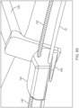
- Each of the plurality of shuttles may be configured for being detachably mechanically coupled to the track, e.g., threaded onto the track or laterally mated to the track.
- Each subsequent one of the plurality of shuttles may be configured for slidably receiving a distal end of a respective one of the plurality of elongate medical devices affixed to a preceding one of the plurality of shuttles, such that the respective elongate medical device affixed to the preceding shuttle is coaxially disposed within a respective one of the plurality of elongate medical devices affixed to the subsequent shuttle.
- one of the plurality of shuttles may be a master shuttle, and another one of the plurality of shuttles may be a slave shuttle.
- the endovascular management and tracking system further comprising a controller (e.g., an electrical controller or a mechanical controller) configured for actuating the axial drive mechanism of the slave shuttle in response to actuation of the axial drive mechanism of the master shuttle, such that the slave shuttle is axially translated along the track in synchronous coordination with the axial translation of the master shuttle along the track.
- a controller e.g., an electrical controller or a mechanical controller
- each of the shuttle(s) may further comprise an on-board fluid management control assembly carried by the sled and configured for being fluidly coupled to the elongate medical device affixed to the respective shuttle.
- the on-board fluid management control assembly may comprise a rotary hemostasis valve (RHV) configured for being removed from the respective shuttle.
- RV rotary hemostasis valve
- the endovascular management and tracking system may further comprises a locking mechanism carried by the sled and configured for being manually operated to alternately engage and disengage the axial drive mechanism to the track.
- the endovascular management and tracking system may further comprise a locking mechanism configured for being manually operated to alternately engage and disengage the axial drive mechanism to the track.
- a distal end of each of the anti-bucking mechanism(s) may be configured for being affixed to a location, and each of the anti-bucking mechanism(s) may be configured for lengthening when the respective shuttle is axially translated away from the location and shortening when the respective shuttle is axially translated toward the location.
- the location to which the distal end of one of the anti-buckling mechanisms is affixed may be a fixed location relative to a patient. If the endovascular management and tracking system comprises a plurality of shuttles, and location to which the distal end of the anti-buckling mechanism of a preceding one of the plurality of shuttles is affixed may be a subsequent one of the plurality of shuttles.
- the anti-bucking mechanism comprises the driver system.
- a robotic endovascular system may comprise the aforementioned endovascular management and tracking system and a master input device configured for receiving manual commands from a user and transmitting control signals to the motor of each of the shuttle(s).
- each of shuttle(s) may optionally comprise a manual actuator configured for actuating the axial drive mechanism.
- an endovascular management and tracking system comprises a track (which may or may not be flexible), a slave shuttle to which a first elongate medical device can be affixed, and a master shuttle to which a second elongate medical device can be affixed.
- the slave shuttle and master shuttle are configured for being mechanically coupled to the track.
- each of the master shuttle and the slave shuttle is configured for being detachably mechanically coupled to the track.
- one of the master shuttle and the slave shuttle is a subsequent shuttle
- the other of the master shuttle and the slave shuttle is a preceding shuttle
- the master shuttle is configured for receiving a distal end of a respective one of the first and second elongate medical devices affixed to a preceding shuttle, such that the respective elongate medical device affixed to the preceding shuttle is coaxially disposed within a respective one of the first and second elongate medical devices affixed to the subsequent shuttle.
- each of first and second elongate medical devices is flexible, in which case, each of at least one of the master shuttle and the slave shuttle further comprises an anti-bucking mechanism configured for preventing the respective elongate medical device from prolapsing in response to axial compression applied to the respective elongate medical device.
- the endovascular management and tracking system further comprises a first axial drive mechanism configured for being actuated to axially translate the slave shuttle along the track.
- the master shuttle further comprises a sled configured for riding on the track, and the first axial drive mechanism and the manual actuator are carried by the sled.
- the endovascular management and tracking system further comprises a controller configured for actuating the first axial drive mechanism in response to axial translation of the master shuttle manually along the track, such that the slave shuttle is axially translated along the track in synchronous coordination with the axial translation of the master shuttle along the track.
- the slave shuttle may comprise a first rotary drive mechanism configured for being actuated to rotate the first elongate medical device about its longitudinal axis relative to the slave shuttle
- the master shuttle may comprise a second rotary drive mechanism configured for being actuated to rotate the second elongate medical device about its longitudinal axis relative to the master shuttle
- the controller is an electrical controller.
- the endovascular management and tracking system may further comprise encoders indicative of a location of the master shuttle relative to track, and one or more sensors configured for reading the encoders and outputting an electrical signal indicating the location of the master shuttle relative to the track.
- the electrical controller may be configured for controlling the first axial drive mechanism based on the electrical signal.
- the encoders may be disposed along the track, and the sensor(s) may be disposed on the master shuttle.
- the encoders may comprise a series of fiducial elements extending along a length of the track, and the sensor(s) may comprise a fiducial element reader configured for reading the fiducial elements.
- the controller is a mechanical controller.
- the slave shuttle may further comprise a first sled configured for riding on the track, and the master shuttle may further comprise a second sled configured for riding on the track.
- the first axial drive mechanism may be carried by the first sled and configured for being actuated to axially translate the slave shuttle along the track
- the second axial drive mechanism may be carried by the second sled and configured for being actuated to axially translate the master shuttle along the track.
- the master shuttle may further comprise a manual actuator carried by the second sled and configured for actuating the second axial drive mechanism
- the slave shuttle may further comprise another manual actuator carried by the first sled and configured for actuating the first axial drive mechanism.
- the mechanical controller may comprise a control shaft mechanically coupled between the first and second axial drive mechanisms (e.g., in a detachable manner).
- the first worm drive may be removably disposed within the slave shuttle.
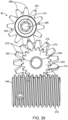
- the first worm drive may comprise a first worm screw and a first worm gear
- the second worm drive may comprise a second worm screw and a second worm gear
- the control shaft may be operably coupled between the first and second worm screws
- the first worm gear may be operably coupled between the first manual actuator and the first worm screw
- the second worm gear may be operably coupled between the second worm screw and the track.
- Each of the first and second worm screws may have a bore through which the control shaft is configured for being disposed, and the bores of the first and second worm screws and the outer periphery of the control shaft may be keyed.
- the master shuttle may further comprise a rotatable manual actuator carried by the sled and configured for actuating the second axial drive mechanism, and the second worm gear may be operably coupled between the rotatable manual actuator and the track.
- the first and second worm screws may have different pitches and/or opposite pitches.
- the slave shuttle is axially translated along the track in synchronous coordination with the axial translation of the master shuttle along the track in accordance with an axial translation ratio.
- the axial translation ratio may be a negative axial translation ratio or a positive axial translation ratio. If the axial translation ratio is a negative axial translation ratio, one of the first and second elongate medical devices may be a stent deployment catheter, and the other of the first and second elongate medical devices may be a pusher member disposed within the stent deployment catheter and affixed to a stent within the stent deployment catheter.
- the control station comprises a master input device comprising a linear array of control elements configured for being manually axially translated along a longitudinal axis, and for being manually rotationally translated about the longitudinal axis.
- each of the control elements is cylindrical.
- the cylindrical control elements have different diameters.
- the control station further comprises at least one processor configured for operably coupling the linear array of control elements respectively to the elongate medical devices by commanding the robotic endovascular management and tracking system to axially translate each of the elongate medical devices in response to manual axial translation of each of the linear array of control elements along the longitudinal axis, and to rotationally translate each of the elongate medical devices in response to manual rotational translation of each of the linear array of control elements about the longitudinal axis.
- the sensor assembly may comprise passive components and at least one active component, in which case, the passive components may be affixed to the control elements, and the active component(s) may be located off of the control elements.
- the sensor assembly may comprise a plurality of active components affixed within the rail respectively adjacent the passive components.
- the passive components comprise fiducial elements affixed around the circumference of each of the control elements.
- the passive components comprise a plurality of passive electromagnetic transponders respectively affixed to the control elements, and the active component(s) comprises an electromagnetic transceiver.
- control station further comprises a sensor box containing the active component(s), the passive components comprise a plurality of mechanical arms cantilevered on the control elements, and free ends of the mechanical arms are configured for operably interacting with the at least one active component within the sensor box.
- control station may further comprise a plurality of single-use sterile control element covers configured for being slid into place respectively over the control elements.
- the sterile control element covers may be configured for overlapping each other, such that slidable fluid seals are formed between adjacent control elements to prevent contaminated fluid transfer between any adjacent control elements.
- control elements are virtual control elements.
- the control station may further comprise a gesture monitoring system configured for capturing hand gestures made by an operator while virtually interacting with the virtual control elements.
- Each of the shuttle(s) are configured for being mechanically coupled to the track, and comprise a sled configured for riding on the track, an axial drive mechanism carried by the sled and configured for being actuated to axially translate the respective shuttle along the track, a first axial motor carried by the sled and configured for actuating the axial drive mechanism, a rotary drive mechanism carried by the sled and configured for being actuated to rotate the respective elongate medical device about its longitudinal axis, and a second motor carried by the sled and configured for actuating the rotary drive mechanism.
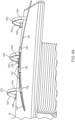
- the robotic endovascular system 10 generally comprises an endovascular assembly 12 (shown best in Fig. 3 ); an endovascular management and tracking system 14 that can be closely associated with a procedure table 18 on which a patient 20 (which in the illustrated embodiment, is a human, but can be any animal) rests and to which the endovascular assembly 12 is operably mounted in a coaxial (or nested) relationship; and a control station 16 communicatively coupled to the endovascular management and tracking system 14, thereby allowing an operator 24 (e.g., a physician) to perform a medical procedure on the patient 20.
- the robotic endovascular system 10 may also comprise a drape 22 (shown in phantom in Fig. 2 ) that at least partially covers the procedure table 18 and patient 20.
- the endovascular assembly 12 comprises a plurality of elongate medical devices 26, and in this case, a guide sheath 26a, a working catheter 26b, and a guidewire 26c, coaxially arranged with respect to each other; that is, the guidewire 26c is sized to be slidably received within the working catheter 26b, and the working catheter 26b is sized to be slidably received within the guide sheath 26a.
- the endovascular assembly 12 may be, e.g., inserted through natural body lumens (e.g., blood vessels (artery, chamber of the heart, or vein), urinary system vessels (renal collection ducts, calix, ureter, bladder, or urethra), hepatobiliary vessels (hapatic and pancreatic ducts, chyle ducts, common or cystic duct), gastrointestinal tract (esophagus, stomach, small and large intestine, cecum, rectum) gynecological tract (cervix, uterus), fallopian tube or milk ducts and mammary canals of breast), nasophyarynx (eustacean tube, sinuses, tear duct), seminal vesicle, spinal canal, or ventricles of the brain).
- the endovascular assembly 12 may be introduced into the patient 20 by percutaneous access, surgical access, or through natural orifices (oral, rectal, nasal, otic, optic, or
- the endovascular assembly 12 is described herein as comprising a tri-axial arrangement of a guide sheath, working catheter, and guidewire with which the endovascular management and tracking system 14 interacts, it should be appreciated that the endovascular assembly 12 may include any combination of a guide sheath, working catheter, and guidewire (including a bi-axial arrangement, and even a mono-axial arrangement (i.e., only one of a guide sheath, working catheter, guidewire, or any other flexible elongate medical instrument) with which the endovascular management and tracking system 14 interacts.
- the guide sheath 26a is configured for facilitating access for the working catheter 26b to target tissue site in the vasculature of the patient 20.
- the guide sheath 26a generally includes an elongate sheath body 28 having a proximal end 30 and a distal end 32, a central lumen 34 (shown best in Fig. 4 ) that extends entirely through the sheath body 28 between the proximal end 30 and distal end 32, and a proximal adapter 36 affixed to the proximal end 30 of the sheath body 28.
- the sheath body 28 is substantially pliable or flexible, such that when it is advanced into the patient 20, an operator or surgeon may easily manipulate the sheath body 28 to conform, adopt, or match the shape or curvatures of the internal pathways (e.g., gastrointestinal tract, blood vessels, etc.) of the patient.
- the internal pathways e.g., gastrointestinal tract, blood vessels, etc.
- the geometry and size of the central lumen 34 will be selected in accordance with the cross-sectional geometry and size of the working catheter 26b.
- the sheath body 28 may have a low-friction inner layer (e.g., a coating of silicone or polytetrafluoroethylene) to provide a low-friction surface to accommodate movement of the working catheter 26b within the working lumen 34 of the guide sheath 26a.
- the proximal adapter 36 is configured for both mechanically and fluidly coupling the guide sheath 26a to the endovascular management and tracking system 14.
- the guide sheath 26a may have active steering capability, such that the distal end 32 of the sheath body 28 may be articulated into simple or complex shapes or curvatures that may conform to various shapes or curvatures of internal pathways of the patient to reach a target tissue site in the vasculature of the patient 20.
- the guide sheath 26a may have one or more steering elements (such as pull wires (not shown)), extending through the sheath body 28, which can be operated to effect the desired shape or curvature at the distal end 32 of the sheath body 28.
- the working catheter 26b is configured for performing an interventional and/or diagnostic procedure at the target tissue site.
- the working catheter 26b may be a stent delivery catheter, a balloon catheter, an electrophysiology catheter, ultrasound imaging catheter, atherectomy catheter, vaso-occlusive device delivery catheter, contrast/medicine delivery catheter, etc.
- the working catheter 26b generally includes an elongate catheter body 38 having a proximal end 40 and a distal end 42, a central lumen 44 (shown best in Fig. 4 ) that extends entirely through the catheter body 38 between the proximal end 40 and distal end 42, and a proximal adapter 46 affixed to the proximal end 40 of the catheter body 38, and an operative element 48 (e.g., a stent, balloon, mapping electrodes, ultrasound element, tissue cutting blade, vaso-occlusive devices, fluid port, etc.) carried by the distal end 42 of the catheter body 38.
- an operative element 48 e.g., a stent, balloon, mapping electrodes, ultrasound element, tissue cutting blade, vaso-occlusive devices, fluid port, etc.
- the working catheter 26b passes through the central lumen 34 of the guide sheath 26a, and is thus, moveable relative thereto.
- the working catheter 26b may be movably positioned within the central lumen 34 of the guide sheath 26a to enable relative insertion of the guide sheath 26a and working catheter 26b, relative rotation or “roll” of the guide sheath 26a and working catheter 26b, and optionally, relative steering or bending of the guide sheath 26a and working catheter 26b relative to each other, particularly when the distal end 42 of the catheter body 38 is inserted beyond the distal end 32 of the sheath body 28.
- the working catheter 26b projects distally with respect to the distal end 32 of the sheath body 28.
- the working catheter 26b may be withdrawn proximally such that the distal end 42 of the catheter body 38 is substantially flush with the distal end 32 of the sheath body 28, or withdrawn proximally even further such that the distal end 32 of the sheath body 28 is retracted within the distal end 32 of the sheath body 28.
- the catheter body 38 is substantially pliable or flexible, such that it can be advanced through the central lumen 34 of the sheath body 28 when the sheath body 28 conforms to the shape or curvatures of the internal pathways of the patient.
- the catheter body 38 has a circular cross-section, although other cross-sectional geometries, such as rectangular, can be used.
- the catheter body 38 may be comprised of multiple layers of materials and/or multiple tube structures that exhibit a low bending stiffness, while providing a high axial stiffness along the neutral axis.
- Typical designs include a nitinol spine encapsulated in braid and any flexible, pliable, or suitable polymer material or bio-compatible polymer material or a braided plastic composite structure composed of low durometer plastics (e.g., nylon-12, Pebax ® , polyurethanes, polyethylenes, etc.).
- the catheter body 38 may be comprised of multiple layers of materials and/or multiple tube structures that exhibit a low bending stiffness, while providing a high axial stiffness along the neutral axis.
- Typical designs include a nitinol spine encapsulated in braid and any flexible, pliable, or suitable polymer material or bio-compatible polymer material or a braided plastic composite structure composed of low durometer plastics (e.g., nylon-12, Pebax ® , polyurethanes, polyethylenes, etc.).
- low durometer plastics e.g., nylon-12, Pebax ® , polyurethanes, polyethylenes, etc.
- the geometry and size of the central lumen 44 will be selected in accordance with the cross-sectional geometry and size of the guidewire 26c.
- the catheter body 38 may have a low-friction inner layer (e.g., a coating of silicone or polytetrafluoroethylene) to provide a low-friction surface to accommodate movement of the guidewire 26c within the central lumen 44 of the working catheter 26b.
- the proximal adapter 46 is configured for both mechanically and fluidly coupling the working catheter 26b to the endovascular management and tracking system 14.
- the working catheter 26b may have active steering capability, such that the distal end 42 of the catheter body 38 may be articulated into simple or complex shapes or curvatures that may conform to various shapes or curvatures of internal pathways of the patient to reach a target tissue site in the vasculature of the patient 20.
- the working catheter 26b may have one or more steering elements (such as pull wires (not shown)), extending through the catheter body 38, which can be operated to effect the desired shape or curvature at the distal end 42 of the catheter body 38.
- the guidewire 26c may be conventional wire that includes a guidewire body 50 having a proximal end 52 and a distal end 54, and a collet 56 affixed to the proximal end 52 of the guidewire body 50.
- the guidewire body 50 is composed of a suitable material (e.g., metal or metal alloy, such as stainless steel and/or nickel-titanium alloy, or polymer) to provide the guidewire 26c with desirable flexibility/stiffness characteristics.
- the guidewire body 50 may have a suitable diameter, e.g., 0.125 inches or less, and have a suitable length in the range of 50cm-350cm.
- the collet 56 is configured for mechanically coupling the guidewire 26c to the endovascular management and tracking system 14.
- each of the proximal adapters 36, 46 comprises an adapter body 58 composed of a suitable material, such as polycarbonate, Acrylonitrile Butadiene Styrene (ABS), or acetal, and a lumen 60 extending axially through the center of the proximal adapter body 58.
- a suitable material such as polycarbonate, Acrylonitrile Butadiene Styrene (ABS), or acetal
- the endovascular management and tracking system 14 can be dynamically switched between a fully automated (robotic) modality that is control of the control station 16 and a fully manual modality that is under manual control of a user without use of the control station 16.
- the endovascular management and tracking system 14 can be operated in a fully manual modality in a dedicated manner (i.e., without the use of motors or controllers at all), thereby providing a "dumb" or “budget" version of the endovascular management and tracking system 14.
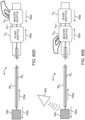
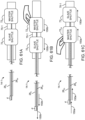
- a rotary drive mechanism 96 (e.g., a geared or frictional coupling) carried by the sled 90 and configured for being actuated to rotate the respective one of the elongate medical devices 26 affixed to the respective shuttle 72 about its longitudinal axis; a rotary actuator 98 (shown in Fig. 7D ) carried by the sled 90 and configured for actuating the rotary drive mechanism 96; and an outer casing 100 mounted to the sled 90 and containing the axial drive mechanism 92, axial actuator 94, rotary drive mechanism 96, and rotary actuator 98.
- the axial actuator 94 and rotary actuator 98 may comprise motors (e.g., stepper motors), such that the motors may, in response to control signals generated by the control station 16, actuate the respective drive mechanisms 92, 96 to axially translate the respective shuttle 72 along the track 70 and rotate the respective one of the elongate medical devices 26 about its longitudinal axis.
- motors e.g., stepper motors
- the endovascular management and tracking system 14 may be advantageously designed to be dynamically switched between the fully automated modality and a fully manual modality.
- each of the shuttles 72a-72c additionally comprises manual actuators 102, 104 (e.g., hand-operated dials, knobs, thumb wheels, sliders, or other hand-actuated mechanism) that can be manually operated to axially index the respective shuttle 72, such that axial movement of the respective shuttle 72 along the track 70 may be finely controlled, and/or rotationally index the respective one of the elongate medical devices 26), such that rotation of the respective elongate medical device 26 about its axis may be finely controlled.
- manual actuators 102, 104 e.g., hand-operated dials, knobs, thumb wheels, sliders, or other hand-actuated mechanism
- the manual actuators 102, 104 may respectively actuate the same drive mechanisms 92, 96 that are respectively actuated by the motors 94, 98, or may respectively actuate different drive mechanisms (not shown) that are completely independent of the drive mechanisms 92, 96 that are respectively actuated by the motors 94, 98.
- any of the shuttles 72a-72c may not have manual actuators 102, 104, and instead, the respective shuttle 72 may be manually translated along the track 70 directly by hand and/or the respective one of the elongate medical devices 26 may be rotated about its longitudinal axis directly by hand).
- each of the shuttles 72a-72c includes one or more actuators (not shown) (e.g., one or more buttons, a slider, touch sensor(s), etc. that can be manually operated to axially translate the respective shuttle 72 along the track 70 or rotate the respective one of the elongate medical devices 26 its longitudinal axis via operation of the respective motors 94, 98 and associated drive mechanisms 92, 96.
- Switching the endovascular management and tracking system 14 between the fully automated modality and the fully manual modality may be accomplished in any one or more of a variety of manners.
- each shuttle 72 includes a first clutching mechanism (not shown) configured for being operated to alternately engage (e.g., via meshing of gears, frictional coupling, motor activation, etc.) and disengage (e.g., de-meshing of gears, frictional decoupling, motor deactivation, etc.) at least a portion of the axial drive mechanism 92 to which the axial motor 94 is associated to and from the track 70, and a second clutching mechanism (not shown) configured for being operated to alternately engage (e.g., meshing of gears, frictional coupling, motor activation, etc.) and disengage (e.g., de-meshing of gears, frictional decoupling, motor deactivation, etc.) at least a portion of the rotary drive mechanism 96 to which the axial motor 94 is associated to and from the respective one of the elongate medical devices 26 affixed to the respective shuttle 72.
- first clutching mechanism (not shown) configured for being operated to alternately engage (e.g.,
- each shuttle 72 may be operated via manual input via the respective shuttle 72, via another shuttle 72, and/or via input from the control station 16, and may optionally include a manual/auto switch with visual indication of engagement or disengagement.
- the manual actuator 102 may actuate the portion of the axial drive mechanism 92 that remains engaged with the track 70 (i.e., the portion of the axial drive mechanism 92 between the clutch point and the track 70) or a completely independent axial drive mechanism to finely control axial translation of the respective shuttle 72 along the track 70
- the manual actuator 104 may actuate the portion of the rotary drive mechanism 96 that remains engaged with the respective one of the elongate medical devices 26 ((i.e., the portion of the rotary drive mechanism 96 between the clutch point and the respective elongate medical device 26) or a completely independent axial drive mechanism to finely control rotation of the respective elongate medical device 26.
- the motors 94, 98 and associated drive mechanisms 92, 96 may be designed to freely spin when electronically deactivated (e.g., powered down or otherwise placed in sleep mode) in response to a low force.
- the free spin capability of the motors 94, 98 and associated drive mechanisms 92, 96 will depend on the type of motors used, the mode of controlling the motors, and the design of the associated drive mechanisms 92, 96.
- electronically activating (e.g., powering on or otherwise waking up) the motors 94, 98 places the endovascular management and tracking system 14 into the fully automated modality (such that the motors 94, 98 may, in response to control signals generated by the control station 18, actuate the respective drive mechanisms 92, 96 to axially translate the respective shuttle 72 along the track 70 and rotate the respective one of the elongate medical devices 26 about its longitudinal axis), and powering down or otherwise putting the motors 94, 98 to sleep places the endovascular management and tracking system 14 into the fully manual modality (such that the manual actuators 102, 104 can be operated to finely control axial translation of the respective shuttle 72 along the track 70 and/or finely rotate the respective elongate medical device 26 about its longitudinal axis; or the respective shuttle 72 may be manually translated along the track 70 directly by hand (e.g., by grasping the outer casing 100 with a hand) and/or the respective elongate medical device 26 may be rotated about its longitudinal
- the respective shuttle 72 may comprise no actuators (e.g., the shuttle 72 may be manually translated along the track 70 directly by hand and/or the respective one of the elongate medical devices 26 may be rotated about its longitudinal axis directly by hand); or the axial actuator 94 and/or rotary actuator 98 may, instead of motors, comprise manual actuators (e.g., hand-operated dials, knobs, thumb wheel or other hand-actuated mechanism) that can be operated to axially index the shuttle 72, such that axial movement of the shuttle 72 along the track 70 may be finely controlled, and/or rotationally index the respective elongate medical device 26), such that rotation of the respective elongate medical devices 26 about their axes may be finely controlled.
- manual actuators e.g., hand-operated dials, knobs, thumb wheel or other hand-actuated mechanism
- each of the shuttles 72a-72c may have a locking mechanism 106 (shown in Figs. 7A and 7D ) for parking or locking the respective shuttle 72 in place on the track 70 to prevent un-commanded movement of the respective shuttle 72 on the track 70 when the shuttle 72 is either in the fully automated modality (in the case, where the motors are incapable of locking the shuttle 72 in place on the track via the first clutching mechanism) or the fully manual modality.
- a locking mechanism 106 shown in Figs. 7A and 7D ) for parking or locking the respective shuttle 72 in place on the track 70 to prevent un-commanded movement of the respective shuttle 72 on the track 70 when the shuttle 72 is either in the fully automated modality (in the case, where the motors are incapable of locking the shuttle 72 in place on the track via the first clutching mechanism) or the fully manual modality.
- the proximal-most shuttle 72c to which the guidewire 26c is affixed may be in close proximity to, and in the illustrated embodiment, may be hard coupled to the medial shuttle 72b, such that the shuttles 72b-72c axially translate along the track 70 as a single unit.
- the proximal-most shuttle 72c comprises a male plug 108 (shown in Fig. 6 ) disposed on the proximal end of the outer casing 100 for removably mating to the loading/unloading port 88 of the medial shuttle 72b.
- an alternative conventional drive mechanism e.g., pinch rollers or caterpillar tractor
- the flush line 114 has a one-way valve to prevent back flow.
- normal saline flow always occurs through the flush line into the RHV 112 unless fluid is injected through the injection port 124, in which case, the one-way valve in the flush line 114 prevents saline flow and only infusion of the contrast into the RHV 112.
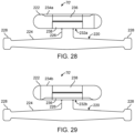
- the axially split sheath 136 comprises an elongate tubular body 138 having a proximal end (not shown) and a distal end 142 (shown in Fig. 6 ), a central lumen 144 extending between the proximal end and distal end 142 of the tubular body 138, and a split 146 axially extending between the proximal end 140 and distal end 142 of the tubular body 138.
- the tubular distal portion 148a lengthens while the flattened proximal portion 148b shortens as the axially split sheath 136 is unfurled from the stowage housing 134, and shortens while the flattened proximal portion 148b lengthens as the axially split sheath 136 is furled within the stowage housing 134.
- the axially split sheath 136 is a composed of an elastomeric or shape recoverable material that is pre-shaped in the tubular state when unfurled from the stowage housing 134, but assumes a flattened state when furled within the stowage housing 134.
- the structure of the axial split sheath 136 may be a simple elastomeric tube, a wire/braid reinforced tube (especially those having a wire with a shape recovery to a cylindrical shape), a laser cut tube (especially those using stiffer materials ranging from stiff polymers, polyether-ether ketone (PEEK), PI, thick polytetrafluoroethylene (PTFE), etc., to metals with yield strains greater than 1%, such as spring steel, nitinol, etc.).
- PEEK polyether-ether ketone
- PI thick polytetrafluoroethylene
- PTFE thick polytetrafluoroethylene
- the axially split sheath 136 may be pre-shaped to have both a tubular state and flattened state, such that the axially split sheath 136 has a bi-stable structure.
- the axially split sheath 136 may be composed of a suitable material, e.g., a carbon fiber composite laminated or impregnated with a polymer, that can be pre-shaped to have a bi-stable structure.
- the axially split sheath 136 will remain in a tubular shape until an application of an external force transitions the axially split sheath 136 to the flattened state, and likewise, the axially split sheath will remain in a flattened state until an application of an external force transitions the axially split sheath 136 from the flattened state to the tubular state. In this manner, the flattened proximal portion 148b of the axially split sheath 136 will not tend to transition to the tubular state, and will thus, fully remain in the flattened state.
- the axially split sheath 136 may be more tightly rolled up within the stowage housing 134 into a more compact form merely by pushing the axially split sheath 136 toward and within the stowage housing 134. In this manner, the axially split sheath 136 may be more consistently unfurled from and furled within the stowage housing 134 without the need for a motorized take-up mechanism that otherwise tension the axially split sheath 136, such that it remains in the flattened state when being furled.
- the distal end 142 of the tubular body 138 is affixed to a location, such that the tubular distal portion 148a of the axially split sheath 136 lengthens when the distance between the respective shuttle 72 and the location increases (i.e., the respective shuttle 72 is axially translated away from the affixation location or the affixation location is axially translated away from the respective shuttle 72), and shortens when the distance between the respective shuttle 72 and the location decreases (e.g., the respective shuttle 72 is axially translated toward the affixation location or the affixation location is axially translated toward the respective shuttle 72).
- the location to which the distal end 142 of the tubular body 138 associated with the distal-most shuttle 72a is affixed is a location relative to the patient 20, e.g., to the sheath anchor 80 used to affix the distal end 74 of the track 70 at or near the access site of the patient 20, and the location to which the distal end 142 of the tubular body 138 associated with the medial shuttle 72b (the "preceding shuttle") is affixed is the distal-most shuttle 72a (the "subsequent shuttle").
- the anti-buckling mechanism 132 further comprises a male connector 150 (e.g., a clip or a plug) affixed to the distal end 142 of the tubular body 138 for removably mating to the loading/unloading port 82 disposed within the proximal end of the sheath anchor 80, thereby providing a firm attachment point to the sheath anchor 80 (in the case where the anti-buckling mechanism 132 provides support for the guide sheath 26a affixed to the distal-most shuttle 72a) or for removably coupling mating to the loading/unloading port 88 formed in the proximal end of the outer casing 100 of the distal-most shuttle 72a, thereby providing a firm attachment point to the distal-most shuttle 72a (in the case where the anti-buckling mechanism 132 provides support for the working catheter 26b affixed to the medial shuttle 72b).
- a male connector 150 e.g., a clip or a plug
- the anti-buckling mechanism 132 provide an affixation means for the distal end 142 of the tubular body 138
- the anti-buckling mechanism 132 of the distal-most shuttle 72a positions the guide sheath 26a for smooth entry into the loading/unloading port 82 of the sheath anchor 80
- the anti-buckling mechanism 132 of the medial shuttle 72b positions the working catheter 26b for smooth entry into the loading/unloading port 88 of the distal-most shuttle 72a.
- the tubular distal portion 148a of the axially split sheath 136 associated with the distal-most shuttle 72a lengthens and the tubular distal portion 148a of the axially split sheath 136 associated with the medial shuttle 72b shortens (see Fig. 11A ).
- the split 146 in the tubular body 138 serves to facilitate placement of the axially split sheath 136 in the flattened state by transversely expanding to allow the tubular body 138 to open up into a ribbon.
- the split 146 in the tubular body 138 also serves to expose the central lumen 144, thereby allowing the guide sheath 26a or working catheter 26b to be transversely loaded into the exposed central lumen 144 at the interface between the tubular distal portion 148a and transition portion 148c of the axially split sheath 136.
- the central lumen 144 is sized to slidably receive the guide sheath 26a or working catheter 26b therein, such that the axially split sheath 136 provides support to the guide sheath 26a or working catheter 26b.
- the axially split sheath 136 may be transversely flexible, the axially split sheath 136 preferably has a sufficient columnar strength, such that the tubular distal portion 148a prevents the guide sheath 26a or working catheter 26b from prolapsing when an axial compression force caused by axial displacement of the shuttles 72a-72b is applied to the guide sheath 26a or working catheter 26b.
- the axially split sheath 136 When the respective one of the shuttles 72a-72b axially translates the respective one of the guide sheath 26a and working catheter 26b in the distal direction, the axially split sheath 136, the tubular distal portion 148a of the axially split sheath 136 lengthens to envelope the respective guide sheath 26a or working catheter 26b at the transition portion 148c.
- the tubular distal portion 148a of the axially split sheath 136 lengthens to peel away from the respective guide sheath 26a or working catheter 26b at the transition portion 148c.
- active unfurling of the axially split sheath 136 from the stowage housing 134 causes axial compression within the axially split sheath 136 between the distal-most shuttle 72a and the location that is fixed relative to the patient 20 (e.g., the sheath anchor 80 used to affix the distal end 74 of the track 70 at or near the access site of the patient 20), thereby, in turn, causing the distal-most shuttle 72a to axially translate in the proximal direction 150'.
- Communications between and within the endovascular management and tracking system 14 and control station 16 may occur through wired or wireless connections or a combination thereof. All standard communication architectures (e.g., ethernet, USB, Wi-Fi, Bluetooth, FireWire, etc.) and all data transfer protocols are envisioned to form either a centralized control like where the control station 16 manages all communications (point-to-point) or a micro-local network where the endovascular management and tracking system 14 and control station 16 communicate with each other in a coordinated manner.
- All standard communication architectures e.g., ethernet, USB, Wi-Fi, Bluetooth, FireWire, etc.
- All data transfer protocols are envisioned to form either a centralized control like where the control station 16 manages all communications (point-to-point) or a micro-local network where the endovascular management and tracking system 14 and control station 16 communicate with each other in a coordinated manner.
- data can be transferred to or from the respective shuttles 72a-72c individual wireless communication links (e.g., via radio frequency (RF), microwave, infrared (IR), inductive coupling via the track 70, or other wireless transmission links) between the respective shuttles 72a-72c and the control station 16 and/or via wireless communications links between the shuttles 72a-72c.
- RF radio frequency
- IR infrared
- the master input device 194 may be configured for causing the endovascular management and tracking system 14 to perform various tasks using the coaxial endovascular assembly 12 (e.g., to advancing, retracting, rotating, optional steering of the guide sheath 26a, working catheter 26b, and guidewire 26c relative to each other, etc.).
- the control station 16 further comprises a control panel 196 (e.g., a pad or on-screen touch control) configured for displaying status and/or non-physical or non-motion input, such as, e.g., text or numeric or on/off information.
- the control panel 196 may be configured for allowing the physician to change general settings, set-up a library for each of the shuttles 72 including associating each of the shuttles 72 with a particular one of the elongate medical devices 26, and to link any of the shuttles 72 with each other to provide synchronization motion between the elongate medical devices 26.
- control panel 196 may allow the operator 24 to perform non-real-time functions, such as locking individual shuttles (described in further detail below), synchronizing the shuttles 72, changing synchronization parameters, such as direction and ratio of motion, performance of interventional/diagnostic functions using the working catheter 26b (e.g., stent delivery, balloon inflation, ablation/mapping of endocardial tissue, ultrasound imaging, atherectomy of a blood vessel, delivery of vaso-occlusive devices into an aneurysm, delivery of contrast/medicine, or to perform any other medical function for which the working catheter 26b is designed), etc.
- non-real-time functions such as locking individual shuttles (described in further detail below), synchronizing the shuttles 72, changing synchronization parameters, such as direction and ratio of motion, performance of interventional/diagnostic functions using the working catheter 26b (e.g., stent delivery, balloon inflation, ablation/mapping of endocardial tissue, ultrasound imaging, atherectomy of a blood vessel, delivery of vaso
- the control panel 196 may optionally display various aspects of the robotic endovascular system 10. For example, an image of the distal end of the coaxial endovascular assembly 12 may be displayed in real time on the control panel 196 to provide the operator 24 with the current orientation of the elongate medical devices 26 as they are positioned within the vasculature of the patient 20.
- the graphical display(s) may also be configured for displaying patient-specific information to the operator 24 (e.g., image data (e.g., x-ray images, MRI images, CT images, ultrasound images, etc.), hemodynamic data (e.g., blood pressure, heart rate, etc.), and patient record information (e.g., medical history, age, weight, etc.).
- control station 16 may be interfaced with an angiographic system (not shown) or its display components, such that the control station 16 (e.g., the control panel 196) may display information or images from the angiographic system, or vice versa.
- control station 16 e.g., the control panel 196
- the control station 16 may be configured to receive input to send commands to the angiographic system to move the procedure table 18 or change the position of the x-ray camera/source.
- the control station 16 e.g., the control panel 196) may also be configured for controlling or triggering other ancillary devices, such as power injectors and infusion pumps.
- control station 16 is affixed to the procedure table 18 via a clamp mechanism 198.
- the clamp mechanism 198 or alternatively a different clamp mechanism (not shown), can be used to affix the proximal end 76 of the track 70 (shown in Fig. 6 ). Having only a single point of attachment allows the control station 16 to be clamped onto a table or similar surface as needed without taking up valuable space in the operating room environment.
- the control station 16 can be setup remotely from the endovascular management and tracking system 14 outside of the radiation field with communications, processing, and interventionalist interfacing with the endovascular management and tracking system 14.
- the master input device 194 may comprise multiple controllers for respectively controlling the motions of the respective elongate medical devices 26 via the shuttles 72.
- the motions of all of the respective elongate medical devices 26 may be independently controlled by the multiple controllers of the master input device 194, or the motions of at least two of the respective elongate medical devices 26 may be linked together to provide synchronized motion (e.g., 1:1 linked motion), such that control of one of the elongate medical devices 26 by one of the multiple controllers of the master input device 194 controls another one of the elongate medical devices 26 in accordance with the linked motion (either axial translation or rotational translation).
- the master input device 194 comprises a linear array of individual control elements 200a-200c and a rail 202 on which the control elements 200a-200c are axially and rotationally slidable (i.e., they may both axially translate along and rotationally translate about a longitudinal axis 204 of the rail 202.
- the use of the linear array of individual control elements 200a-200c for independently manipulating the elongate medical devices 26a-26c uses similar motions to those used in the context of manual catheter lab device manipulation, and thus, would allow physicians to perform familiar and intuitive endovascular procedures.
- the operator 24 may grasp one of the control elements 200a-200c and move the grasped control element along the longitudinal axis 204 of the rail 202 (either proximally or distally) to axially translate the elongated medical device 26 (either proximally or distally) that is controlled by the grasped control element 200, or rotate the grasped control element about the longitudinal axis 204 of the rail 202 (either clockwise or counterclockwise) to rotationally translate the elongated medical device 26 (either clockwise or counterclockwise) that is controlled by the grasped control element 200.
- the rail 202 may be rigid to provide the control elements 200a-200c with only two degrees-of-freedom (DOF) (i.e., linear translation along the longitudinal axis 204 of the rail 202 (z-direction) and rotational translation about the longitudinal axis 204 of the rail 202 (roll), or may be flexible to provide the control elements 200a-200c with additional four DOFs (i.e., linear translation along the x- and y-directions and pitch and yaw relative to the longitudinal axis 204 of the rail 202).
- DOF degrees-of-freedom
- the rail 200 is straight, such that the array of control elements 200a-200c arranged on the rail is rectilinear, although in alternative embodiment, the rail 200 may be slightly curved, such that the array of control elements 200a-200c arranged on the rail are slightly curvilinear.
- the control elements 200a-200c are illustrated as being cylindrical in nature to emulate the proximal ends of the elongate medical devices 26a-26c, it should be appreciated that the control elements 200a-200c may have any suitable cross-section other than circular, including oval, ellipsoidal, polygonal (e.g., triangular, rectangular, hexagonal, octagonal, etc.), etc.
- the individual control elements 200a-200c may be operatively associated with the respective shuttles 72a-72c, such that each control element controls movement (axial and rotational) of the guide sheath 26a, working catheter 26b, or guidewire 26c affixed to the respective one of the shuttles 72a-72c.
- the control elements 200a-200c are axially and rotationally spring-loaded, such that they return to their nominal axial translation and rotational translation positions when released by the operator 24.
- These nominal axial translation and rotational translation positions are preferably in the centers of the axial translation ranges and rotational translation ranges, such that the control elements 200a-200c may have positive and negative travel ranges from the nominal positions (i.e., a forward axial translation range, a reverse axial translation range, a clockwise rotational translation range, and a counterclockwise rotational translation range).
- the rail 202 has an open end by virtue of clamping the control station 16 at only one point via the clamping mechanism 196, thereby facilitating quick exchange of the control elements 200a-200c.
- Each of the control elements 200a-200c may be removably affixed to the rail 202, such that control elements 200 may interchangeable in that they can be added to or removed from the master input device 194, as needed.
- the rail 202 may be reusable, it is desired that the control elements 200a-200c be single-use and disposable. Thus, the used control elements 200a-200c may be easily removed from the rail 202 and discarded and replaced with new and sterilized control elements 200a-200c.
- the master input device 194 may comprise any suitable number of control elements 200, ultimately depending on the number of shuttles 72 used.
- the master input device 194 may comprise less three control elements 200, e.g., if less than three shuttles 72 are used, or more than three control elements 200, e.g., if more than three shuttles 72 are used.
- the master input device 194 may comprise joy-sticks, keypads or keyboards, sliders, roller balls, touch sensors, touch screens, mouses, etc.
- control elements 200a-200c are progressively larger or smaller in diameter to visually or tactilely indicate to the physician which of control elements 200a-200c are associated to the respective one of the elongate medical devices 26a-26c (e.g., the distal-most control element 200a may be operatively associated with the guide sheath 26a and may have a relatively large diameter, the medial control element 200b may be operatively associated with the working catheter 26b and have a relatively moderate diameter, and the proximal-most element 200c may be operatively associated with the guidewire 26c, and may have a relatively small diameter).
- the distal-most control element 200a may be operatively associated with the guide sheath 26a and may have a relatively large diameter
- the medial control element 200b may be operatively associated with the working catheter 26b and have a relatively moderate diameter
- the proximal-most element 200c may be operatively associated with the guidewire 26c, and may have a relatively small diameter
- the control station 16 may optionally comprises a sterile sleeve 206 configured for covering the master input device 194, thereby providing a sterile barrier between the operator 24 and the non-sterile components of the control station 16.
- a sterile sleeve 206 configured for covering the master input device 194, thereby providing a sterile barrier between the operator 24 and the non-sterile components of the control station 16.
- the rail 202 is cantilevered, so that the sterile sleeve 206 can be easily slid over the array of control elements 200 from the free end of the rail 202 to the fixed end of the rail 202.
- the sterile sleeve 206, or a separate sterile sleeve (not shown) may also cover the control panel 196.
- the sterile sleeve 206 should allow unrestricted motion of each of the control elements 200.
- the slidable fluid seals 210 may be formed by a slip fit between the control elements 200a-200c or a sealing member, such as, e.g., an O-ring. As illustrated in Fig. 20 , the sterile control element covers 208a-208c may be packaged as a set of collapsed stacked "cups" that can be slid over the control elements 200a-200c.
- the control station 16 may optionally include various indicators in the form of lights, colored/non-colored segments of mechanical interfaces or sound cues, which may communicate power, manual mode/automated mode, fluid flow or fluid switch state, motion, or errors (e.g., excessive force or torque, controller errors, communication errors, low battery, etc.).
- various indicators in the form of lights, colored/non-colored segments of mechanical interfaces or sound cues, which may communicate power, manual mode/automated mode, fluid flow or fluid switch state, motion, or errors (e.g., excessive force or torque, controller errors, communication errors, low battery, etc.).
- the control station 16 further comprises one or more devices for providing feedback (e.g., visual, audible, haptic, etc.) to the operator 24.
- the control station 16 may have a haptic interface 214 that connects the operator 24 and the coaxial endovascular assembly 14 through a sense of touch, also known as kinesthetic stimulation or tactile feedback.
- the haptic interface 214 communicates tactile feedback to the operator 24 via, e.g., the master input device 194, as input commands are provided via the master input device 194, so that the operator 24 feels resistance representing the direction and magnitude of forces exerted on the elongate medical devices 26 as they are moved within the vasculature of the patient 20.
- the haptic interface 214 creates and transfers the haptic feedback to the operator 24 using actuators (not shown).
- actuators for example, motors capable of translating motor torque to a resistance (counterforces and vibrations) of controller motion to allow the operator 24 to feel when the elongate medical devices 26 are become difficult to move.
- Other examples of translating tactile feedback to the operator 24 include using weight, pneumatic, magnetic, electrical artificial muscles (electroactive polymers), piezo electric, ultrasound, pressure actuators, etc.
- a medical imager may provide visual feedback of forces exerted on the elongate medical devices 26a-26b to the processor 212, which will accordingly control the haptic interface 214 to provide the tactile feedback to the operator 14.
- the medical imager may detect contact between the distal tips of the elongate medical devices 26a-26c and a vessel wall or lesion, or may detect bending of the elongated medical devices 26a-26c.
- the processor 212 may then use this visual feedback to estimate the forces exerted on the elongate medical devices 26a-26c.
- the haptic interface 214 may alternatively have a wearable form factor, such as rings, gloves, finger tip pads, wrist bands, etc., or may even generate non-contact force fields using, e.g., ultrasound pads, air pressure-based feedback, fluid viscosity change-based feedback, etc.
- the control panel 196 or other graphical displays may also display force build up in the elongate medical devices 26 as they are being moved via the master input device 194.
- the master input device 194 optionally comprises an identifier (ID) 218 (e.g., a barcode, QR code, or radiofrequency identifier (RFID)) affixed to each of the control elements 200a-200c (or alternatively, each of the sterile covers 208a-208c disposed over the control elements 200a-200c) for allowing quick identification of the type of elongate medical device 26 (e.g., either guide sheath 26a, a working catheter 26b, or a guidewire 26c) with which the respective control element 200 is associated.
- ID identifier
- RFID radiofrequency identifier
- each control element 200 may be identification (ID)-coupled with a corresponding shuttle 72 (i.e., the control element 200a and shuttle 72a are paired, the control element 200b and shuttle 72b are paired, and the control element 200c and shuttle 72c are paired) via the ID 218 and may be packaged together.
- ID identification
- the corresponding two of the control elements 200 may be pre-paired and packaged together with a label that identifies the ratio of the linked motion (e.g., 1:1, 2:1, 1:2, etc.) between the pair of elongate medical devices 26 that the pre-paired control elements 200 are designed to effect.
- the axial translation and rotational translation (and optionally axial speed and rotational speed) of the control elements 200a-200c may be detected via a sensor assembly, such that the elongate medical devices 26a-26c may be axially translated and rotationally translated in accordance with the mapping algorithm briefly described above.
- the sensor assembly outputs signals indicative of the detected axial translation of each of the control elements 200a-200c along the longitudinal axis 204, and indicative of the detected rotational translation of each of the control elements 200a-200c about the longitudinal axis 204.
- the processor 212 may then command the endovascular management and tracking system 14 to axially translate and rotationally translate each of the elongate medical devices 26a-26c in response to the control signals output by the sensor assembly.
- control elements 200a-200c may be designed to be single-use and disposable.
- the relatively inexpensive components of the sensor assembly e.g., the passive components (i.e., components that are not powered)
- the relatively expensive components e.g., the active components (i.e., components that are powered)
- the relatively expensive components e.g., the active components (i.e., components that are powered)
- the master input device 194 comprises a plurality of encoders in the form of fiducial elements 219 circumferentially disposed around each of the control elements 200a-200c (or alternatively, each of the sterile covers 208a-208c disposed over the control elements 200a-200c), and a vision tracking system 221 (e.g., one or more cameras) configured for visually sensing the fiducial elements 219 disposed on the control elements 200a-200c, and thus, the axial translation and rotational translation (and optionally axial speed and rotational speed) of each of the control elements 200a-200c.
- a vision tracking system 221 e.g., one or more cameras
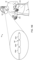
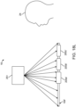
- the master input device 194 comprises a plurality of electromagnetic passive transponders 223, each of which is incorporated into a respective one of the control elements 200a-200c (or alternatively, each of the sterile covers 208a-208c disposed over the control elements 200a-200c), and a stationary electromagnetic transceiver 225 configured for transmitting electromagnetic energy 227 that impinges on the electromagnetic passive transponders 223, which encode the electromagnetic energy with positional information, and in particular, with the axial translations (z-locations) and rotational translations (rolls) of the electromagnetic passive transponders 223, and thus, the control elements 200a-200c.
- the electromagnetic transceiver 225 then receives the encoded electromagnetic energy 229 emitted by the electromagnetic passive transponders 219, which electromagnetic energy 229 can then be decoded to determine the axial translations and rotational translations of the control elements 200a-200c.
- the positional information encoded into the emitted electromagnetic energy 229 by the electromagnetic passive transponders 223 may additionally comprise the x- and y-locations, as well as the pitch and yaw, of the electromagnetic passive transponders 219, and thus, the control elements 200a-200c, such that six degrees of freedom (DOF) (i.e., x-, y-, and z-locations and roll, pitch, and yaw) of the control elements 200a-200c can be determined.
- DOF degrees of freedom
- control elements 200a-200c may be composed of an optically transparent material, and the passive elements 233 may take the form of a series of engravings (e.g., a grating) embedded around the control elements 200a-200c.
- a laser light may be passed through the gratings within the control elements 200a-200c, e.g., from a laser source (not shown) disposed within the rail 202.
- the gratings encode the laser light with positional information via diffraction, and in particular, with the axial translations (z-locations) and rotational translations (rolls) of the control elements 200a-200c.
- the sensors 231 may be optical detectors that measure the encoded laser light diffracted by the gratings, which diffracted laser light can then be decoded to determine the axial translations and rotational translations of the control elements 200a-200c.
- the passive elements 233 may be resistors, in which case, the sensors 231 may electrically sense the locations of the respective passive elements 233, and thus, the axial translation and rotational translation of the control elements 200a-200c; or may be ferric elements, in which case, the sensors 231 may magnetically sense the locations of the respective passive elements 233; or may be coils, in which case, the sensors 231 may inductively sense the locations of the respective passive elements 233; or may be capacitive plates, in which case, the sensors 231 may capacitively sense the locations of the respective passive elements 233; or may be ultrasonically reflective elements, in which case, the sensors 231 may ultrasonically sense the locations of the respective passive elements 233; and so forth.
- the master input device 194 comprises a plurality of mechanical arms 235a-235c, each of which is cantilevered to an end of a respective one of the control elements 200a-200c, and a sensor box 237 comprising sensors (not shown) in which the free ends of the mechanical arms 235a-235c operatively interact (e.g., optically, electrically, magnetically, inductively, capacitively, ultrasonically, etc.) within the sensor box 237.
- the respective lengths of the mechanical arms 235a-235c depend upon the relative locations of the control elements 200a-200c on the rail 202.
- the length of the mechanical arm 235a cantilevered to the distal-most control element 200a will be relatively short
- the length of the mechanical arm 235c cantilevered to the proximal-most control element 200c will be relatively long
- the length of the mechanical arm 235b cantilevered to the medial control element 200b will be relatively moderate.
- the mechanical arms 235a-235c do not mechanically interfere with each other when any of the control elements 200a-200c are rotated about the longitudinal axis 204 of the rail 202
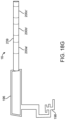
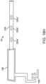
- the mechanical arms 235a-235c are clocked from each other (e.g., 120 degrees apart from each other) and have a limited rotational range (e.g., 120 degrees), as best illustrated in Fig. 18F .
- the mechanical arms 231 may be clocked from each other a different amount and may have a different limited range (e.g., 180 degrees if the maximum number of control elements 200 that can be located on the rail 202 is two, and 90 degrees if the maximum number of control elements 200 that can be located on the rail 202 is four).
- relatively inexpensive accelerometers may optionally be incorporated into each of the control elements 200a-200c, such that the linear speeds and/or angular speeds of the control elements 200a-200c may be determined.
- the touchscreen 239 is cylindrical or semi-cylindrical that displays at least arcuate portions of a linear array of control icons 200a'-200c'.
- the arcuate touchscreen 239 may be, e.g., resistive or capacitive, and may have, e.g., an organic light emitting diode (OLED) touch sensitive surface.
- OLED organic light emitting diode
- the surface of the 3D touchscreen 239 is separated into distinct illuminated regions corresponding to the control icons 200a'-200c'.
- One of the control icons 200a'-200c' may be touched to allow the operator 24 to manipulate that control icon.
- the distinct illuminated regions having outlines, such that the operator 24 can easily distinguish the control icons 200a'-200c' from each other. In other embodiments, the distinct regions may be illuminated with different color or patterns.
- the selected one of the control elements 200a'-200c' may be displayed statically on the 3D touchscreen 239 or may be dynamically displayed as linearly moving along the 3D touchscreen 239 with the hand of the operator 24, thereby providing a better indication of the axial locations of the elongate medical devices 26a-26c relative to each other.
- the 3D touchscreen 239 may display control icons 200a"-200c" (e.g., rectangles) that are designed to be moved using a fingertip of the operator 24.
- any of the control icons 200a"-200c" may be moved along the axis of the 3D touchscreen 239.
- the operator 24 may move their hand along the longitudinal axis of the 3D touchscreen 239 and/or around the circumference of the 3D touchscreen 239, which emulates the axial translation and/or rotational translation of a physical control element.
- control station 16 including the master input device 194 and control panel 196, have been described and illustrated as being physical devices that exists in the real world, and thus, can be physically touched by the operator 24, in alternative embodiments, one or both of a master input device and control panel of the control station 16 may be virtual. As such, the operator 24 need not have to touch a physical master input device or control panel, thereby mitigating sanitation and spatial issues.
- the control station 16 may comprise a head-mounted extended reality (XR) device (e.g., a virtual reality (VR), augmented reality (AR), or mixed reality (MR) device) 241 configured for presenting digitally reproduced images to the operator 24 in a three-dimensional (3D) environment, such that the operator 24 perceives the digitally reproduced images as real.
- XR device 241 is configured for displaying a virtual master input device 194' having virtual control elements 200a'-200c' in the 3D environment of the operator 24.
- the operator 24 may virtually interact with the virtual control elements 200a'-200c' of the virtual master input device 194' as if the operator 24 were physically interacting with the control elements 200a-200c of the master input device 194 illustrated in Fig. 18 .
- the XR device 241 may also display a control panel (not shown) as a two-dimensional (2D) image, as well as real-time medical imaging (e.g., a fluoroscopic image) of the vasculature target site of interest in the patient 20 and video of the hospital room environment, including the endovascular management and tracking system 14', e.g., in the corner of the screen of the XR device 241.
- a control panel not shown
- real-time medical imaging e.g., a fluoroscopic image
- the XR device 241 may display a virtual control panel (not shown) in the 3D environment of the operator 24.
- the control station 16 further comprises haptic feedback gloves 243 (e.g., HaptX ® gloves) that can be worn on the hands of the operator 24 for capturing the hand gestures made by the operator 24 while virtually interacting with the virtual control elements 200a'-200c' of the virtual master input device 194'.
- haptic feedback gloves 243 e.g., HaptX ® gloves
- Such hand gestures may include, e.g., grasping one of the virtual control elements 200a'-200c' with the hand of the operator 24, and moving the grasping hand along the axis of the virtual master input device 194' or rotating the grasping hand about the axis of the master input device 194' in the same manner as the operator 24 may physically grasp one of the physical control elements 200a-200c and move the physical control element along the axis of the physical master input device 194 or rotating the grasped hand about the axis of the physical master input device 194 of Fig. 18 .
- the captured hand gestures can be output by the MR device 241 to the processor 212, which may interpret the hand gestures and issue commands to the endovascular management and tracking system 14 in accordance with a mapping algorithm that maps the interpreted hand gestures to the desired axial translation and rotational translation of the elongate medical devices 26a-26c.
- the haptic feedback gloves 243 also serves as the haptic interface 214 (illustrated in Fig. 18 ) to provide tactile feedback to the operator 24 as the operator 24 virtually interacts with the virtual control elements 200a'-200c' of the virtual master input device 194', so that the operator 24 feels resistance representing the direction and magnitude of forces exerted on the elongate medical devices 26 as they are moved within the vasculature of the patient 20.
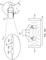
- the control station 16 comprises, instead of haptic feedback gloves 243, a stationary gesture monitoring system 245 (e.g., a device similar to the sensor of the Xbox Kinect ® or a light detection and ranging (LIDAR) sensor assembly), and one or more haptic ultrasound pads 247.
- the gesture monitoring system 245 is configured for capturing the hand gestures made by the operator 24 while virtually interacting with the virtual control elements 200a'-200c' of the virtual master input device 194', and for providing the captured hand gestures to the processor 212 for interpretation.
- the XR device 241 comprises forward-facing cameras (not shown) configured for capturing images of the hand gestures made by the operator 24 while virtually interacting with the virtual control elements 200a'-200c' of the virtual master input device 194', and for providing the captured images of the hand gestures to the processor 212 for interpretation.
- the operator 24 may wear gloves (not shown) covered with fiducial elements that can be more easily sensed by the stationary gesture monitoring system 245 or alternatively the forward-facing cameras of the XR device 241 to capture the hand gestures made by the operator 24.
- the haptic ultrasound pad(s) 247 serve as the haptic interface 214 (illustrated in Fig. 18 ) by emitting ultrasound pressure waves that exert force on the hands of the operator 24, thereby providing tactile feedback to the operator 24 as the operator 24 virtually interacts with the virtual control elements 200a'-200c' of the virtual master input device 194', so that the operator 24 feels resistance representing the direction and magnitude of forces exerted on the elongate medical devices 26 as they are moved within the vasculature of the patient 20.
- multiple ultrasound pads 247 are oriented in different orientations to provide directionally for the tactile feedback provided to the operator 24.
- the processor 212 may augment the master input device 194 in response to the captured hand gestures made by the operator 24, e.g., by moving the displayed control elements 200a-200c in accordance with the hand gestors or otherwise augmenting the displayed control elements 200a-200c, e.g., with different colors.
- the control station 16 comprises, instead of an XR system, a holographic machine 251 configured for displaying a virtual master input device 194' having virtual control elements 200a'-200c', and optionally a virtual control panel, in the 3D environment of the operator 24.
- the holographic machine 251 projects the virtual master input device 194' into the 3D environment of the operator 24.
- the operator 24 may interact with the virtual control elements 200a'-200c' of the virtual master input device 194' in the same manner discussed above with respect to the XR device 241 of Fig. 18I .
- Hand gestures may be captured by, e.g., haptic feedback gloves 243 (shown in Fig. 18I ) worn on the hands of the operator 24 or the stationary gesture monitoring system 245 (shown in Fig. 18J ).
- Tactile feedback can be provided to the operator 24 by, e.g., haptic feedback gloves 243 (shown in Fig. 18I ) worn on the hands of the operator 24 or the haptic ultrasound pad(s) 247 (shown in Fig. 18J ).
- each of the virtual control elements 200a'-200c' in any of the embodiments described above may be virtually axially and rotationally spring-loaded, such that they return to their nominal axial translation and rotational translation positions when virtually released by the operator 24.
- These nominal axial translation and rotational translation positions are preferably in the centers of the axial translation ranges and rotational translation ranges, such that the control elements 200a'-200c' may have positive and negative travel ranges from the nominal positions (i.e., a forward axial translation range, a reverse axial translation range, a clockwise rotational translation range, and a counterclockwise rotational translation range).
- the master input devices 194, 194' illustrated in Figs. 18A-18L have been described as controlling the catheter tracking and management system 14 illustrated in Figs. 1-17 , the master input devices 194, 194' illustrated in Figs. 18A-18L may be employed to control any robotic catheter system, wherein the elongate medical devices are coaxially arranged and may axially and rotationally translate relative to each other, including those that do not have shuttles that translate along a track.
- the processor 212 may issue commands to the endovascular management and tracking system 14 in accordance with a mapping algorithm that maps the sensed axial translation and rotational translation of the control elements 200a-200c (or virtual control elements 200a'-200c') to the desired axial translation and rotational translation of the elongate medical devices 26a-26c. That is, in response to an input comprising the axial translation or rotational translation of the control elements 200a-200c (or virtual control elements 200a'-200c'), the mapping algorithm outputs the desired axial translation or rotational translation of the elongate medical devices 26a-26c. The processor 212 may then translate the output of the mapping algorithm into commands that are sent to the endovascular management and tracking system 14, and in particular, the motors of the endovascular management and tracking system 14 to facilitate these desired axial translations or rotational translations.
- a mapping algorithm that maps the sensed axial translation and rotational translation of the control elements 200a-200c (or virtual control elements 200a'-200c') to the desired
- control elements 200a-200c may be axially and rotationally spring-loaded, such that they return to their nominal axial translation and rotational translation positions when physically released by the operator 24, or the virtual control elements 200a'-200c' may be virtually axially and rotationally spring-loaded, such that they return to their nominal axial translation and rotational translation positions when virtually released by the operator 24.
- the mapping algorithm will only axially translate (proximally or distally) or rotationally translate (clockwise or counterclockwise) each of the elongate medical devices 26a-26b in response to axial translation or rotationally translation of the corresponding control element 200 away from their neutral positions (i.e., against the physical spring force or virtual spring force).
- axially translation or rotational translation of the elongate medical device 26a-26c will cease to occur in response to the operator 24 physically releasing the control element 200a-200c or virtually releasing the virtual control elements 200a'-200c'.
- the corresponding elongate medical device 26 may be incrementally axially translated or rotationally translated.
- the mapping algorithm outputs an axial translation for each elongate medical device 26 in response to an input of an axial translation of the corresponding control element 200 (or virtual control element 200') in accordance with an axial translation ratio, and likewise outputs a rotational translation for each elongate medical device 26 in response to an input of a rotational translation of the corresponding control element 200 (or virtual control element 200') in accordance with a rotational translation ratio.
- the axial translation ratio and the rotational translation ratio will be positive.
- the mapping algorithm will output an axial translation for each elongate medical device 26 in the distal direction in response to an input of an axial translation of the corresponding control element 200 (or virtual control element 200') in the distal direction, and will output an axial translation for each elongate medical device 26 in the proximal direction in response to an input of an axial translation of the corresponding control element 200 (or virtual control element 200') in the proximal direction.
- mapping algorithm will output a rotational translation for each elongate medical device 26 in the clockwise direction in response to an input of a rotational translation of the corresponding control element 200 (or virtual control element 200') in the clockwise direction, and will output a rotational translation of each elongate medical device 26 in the counterclockwise direction in response to an input of a rotational translation of the corresponding control element 200 (or virtual control element 200') in the counterclockwise direction.
- the rotational translation ratio be 1:1 or unity (i.e., rotational translation for each elongate medical device 26 will exactly track the rotational translation of the corresponding control element 200 (or virtual control element 200').
- the axial translation ratio be >1:1 or less than unity (i.e., axial translation for each elongate medical device 26 will be less the axial translation of the corresponding control element 200 (or virtual control element 200').
- the rotational translation ratio may be different than unity, while the axial translation ratio may be 1:1 or unity.
- Either or both of the axial translation ratio and rotational translation ratio may be constant, such that there is a linear relationship between the input of the axial translation or rotational translation of a control element 200 or virtual control element 200' into the mapping algorithm and the respective axial translation or rotational translation of the corresponding elongate medical device 26 output by the mapping algorithm.
- either or both of the axial translation ratio and rotational translation ratio may vary over time, such that there is non-linear relationship between the axial translation or rotational translation of a control element 200 or virtual control element 200' input into the mapping algorithm and the respective axial translation or rotational translation of the corresponding elongate medical device 26 output by the mapping algorithm.
- the axial translation ratio or rotational translation ratio may be initially higher (e.g., to quickly overcome in static frictional forces between the elongate medical device 26 and the vasculature) and then decrease.
- the axial translation ratio or rotational translation ratio may vary in accordance with a custom profile that is designed for the particular operator 24.
- Such custom profile may be manually generated, or alternatively, such custom profile may be generated via a calibration procedure or may be dynamically adapted to the particular operator 24 over a period of time.
- the mapping algorithm may modulate either or both of the axial translation ratio and rotational translation ratio, e.g., to ensure that the elongate medical devices 26a-26c are axially translated or rotationally translated in a smooth manner.
- any tremor in the hands of the operator 24 may cause a control element 200 or virtual control element 200' to axially translate or rotationally translate in a disjointed manner.
- the mapping algorithm may smooth out (e.g., via integration) the input of the disjointed axial translation or rotational translation of the control element 200 or virtual control element 200', such that the output of the desired axial translation or rotational translation of the corresponding elongate medical device 26 is smooth.
- the mapping algorithm may introduce small amplitude axial or rotational vibrations into the input of the axial translation or rotational translation of the control element 200 or virtual control element 200', such that the output of the desired axial translation or rotational translation of the corresponding elongate medical device 26 has small amplitude axial or rotational vibrations, e.g., to avoid static frictional forces between the elongate medical device 26 and the vasculature of the patient 20, thereby facilitating distal advancement of the elongate medical device 26.
- the mapping algorithm may output an axial velocity for each elongate medical device 26 in response to an input of an axial translation of the corresponding control element 200 (or virtual control element 200'), and likewise outputs a rotational velocity for each elongate medical device 26 in response to an input of a rotational translation of the corresponding control element 200 (or virtual control element 200').
- the axial velocity will be in the same direction as the axial translation of the corresponding control element 200 (or virtual control element 200'), while the rotational velocity will be in the same direction as the rotational translation of the corresponding control element 200 (or virtual control element 200').
- the mapping algorithm will output an axial velocity for each elongate medical device 26 in the distal direction in response to an input of an axial translation of the corresponding control element 200 (or virtual control element 200') in the distal direction, and will output an axial velocity for each elongate medical device 26 in the proximal direction in response to an input of an axial translation of the corresponding control element 200 (or virtual control element 200') in the proximal direction.
- the mapping algorithm will output a rotational velocity for each elongate medical device 26 in the clockwise direction in response to an input of a rotational translation of the corresponding control element 200 (or virtual control element 200') in the clockwise direction, and will output a rotational velocity for each elongate medical device 26 in the counterclockwise direction in response to an input of a rotational translation of the corresponding control element 200 (or virtual control element 200') in the counterclockwise direction.
- the mapping algorithm outputs a uniform axial velocity or uniform rotational velocity for each elongate medical device 26 in response to any axial translation or rotational translation of the corresponding control element 200 (or virtual control element 200').
- the mapping algorithm outputs an axial velocity or rotational velocity for each elongate medical device 26 that varies depending on the extent or the speed at which the corresponding control element 200 (or virtual control element 200') is axially translated or rotationally translated. For example, if the control element 200 (or virtual control element 200') is axially translated or rotationally translated a relative long distance or relatively quickly, the mapping algorithm may output an axial velocity or rotational velocity of the corresponding elongate medical device 26 that is relatively high.
- each track segment 70' is specifically designed, such that multiple track segments 70' may be removably coupled to each other to create a track having a variable length.
- a track may be lengthened by adding one or more track segments 70', and shortened by subtracting one or more track segments 70'.
- the track may be better conformed to the hospital room environment.
- the total length of the track may be customized to the contoured distance between the control station 16 (shown in Figs.
- the track rack 220 comprises an elongated base 224 configured for being stably rested on the drape 22 (shown in Figs. 1-2 ) and one or more pedestals 226 (shown best in Figs. 26 and 28 -29 ) affixed on top of the base 224 and to which the track rail 222 is affixed.
- the track rail 222 can be raised above the drape 22, such that the shuttle 72' can freely ride along the track rail 222 without impingement by the hospital room environment, and in particular, the drape 22 upon which the track segment 70' will likely lay.
- the base 224 takes the form of a rectangular frame having a pair of elongated frame members 228 and a series of crossbars 230 affixing the pair of elongated frame members 228 together (best shown in Figs. 25 and 27 ), and in particular, spanning across the width of the base 224 and periodically spaced along the length of the base 224.
- the base 224 is planar, such that the track segment 70', like the track 70 illustrated in Fig. 6 , has a relatively high top-to-bottom (vertical) flexibility, but a relatively low side-to-side (horizontal) and torsional flexibility (i.e., high horizontal and torsional rigidity).
- the track segment 70' may better conform to the contours of the hospital room environment solely in response to gravity (e.g., when laid down on the procedure table 18, patient 20, and/or drape 22), while allowing the shuttle 72' to apply the required drive forces to the track 70' in order to axially translate the shuttle 72' along the coupled track segment 70'.
- the horizontal and torsional rigidity of the track segment 70' may be adjusted without significantly modifying the vertical flexibility of the track segment 70' by varying the number of crossbars 230 that affix the elongate frame members 228 together.
- the track segment 70' comprises a pair of track couplers 232 disposed at opposite ends of each track segment 70', and in the illustrated embodiment, at opposite ends of the track rail 222 of each track segment 70'.
- the track couplers 232 are complementary to each other, such track segments 70' may be removably coupled to each other by engagement of corresponding couplers 232 of adjacent track segments 70'.
- a track coupler 232a disposed on a proximal end 234a of the track rail 222 comprises a recess 236 (best shown in Figs. 25 and 28 ) formed in the bottom surface of the track rail 222, and a tab 238 extending from the proximal end 234a of the track rail 222.
- a track coupler 232b disposed on a distal end 234b of the track rail 222 comprises a recess 236 (best shown in Fig. 27 and 29 ) formed in the top surface of the track rail 222, and a tab 238 extending from the distal end 234b of the track rail 222.
- the track segments 70' may be decoupled from each other by disengagement of the corresponding recess 236 and tab 238 of adjacent track segments 70' (i.e., the tab 238 at the proximal end 234a of the track rail 222 of one track segment 70' can be disengaged from (e.g., snapped out of) the corresponding recess 236 at the distal end 238b of the track rail 222 of the other track segment 70', thereby decoupling the track segments 70' from each other.
- corresponding track couplers 232 may be utilized to removably coupled multiple track segments together.
- the outer casing 100' comprises an upper casing portion 100a' affixed to the top of the sled 90' and a bottom casing portion 100b' affixed to the bottom of the sled 90'.
- the bottom casing portion 100b' comprises an open channel 240 through which the track segment 70' is slidably received.
- the cross-section of the open channel 240 is closely toleranced to the cross-section of the track rail 222 of the other track segment 70', such that shuttle 72' may stably ride along the track segment 70'.
- the shuttle 72' further comprises motor mount brackets 246 that affix the motors 94', 98' to the sled 90'.
- the motor mount brackets 246 and sled 90' have a unibody design, although in alternative embodiments, the motor mount brackets 246 may be directly affixed to the sled 90' via appropriate fasteners (e.g., screws) for stably supporting the respective motors 94', 98' relative to the sled 90'.
- the axial drive mechanism 92' takes the form of a drive train comprising a worm screw 248 affixed to the motor shaft 244 of the axial motor 94', a worm-to-cog gear 250 operably coupled to the worm screw 248, a cog gears 254 operably coupled to the worm-to-cog gear 250, and a pinion gear 256 (shown in Figs. 34 and 36 -39) operably coupled between the cog gear 254 and the teeth 84' of the track segment 70' (shown in Figs. 25-27 ) in a rack-and-pinion arrangement.
- the worm screw 248 drives the worm-to-cog gear 250, which, in turn, drives the cog gear 254, which, in turn, drive the pinion gear 256, which in turn, engages the teeth 84' of the track segment 70' to axially translate the shuttle 72' along the track segment 70'.
- the shuttle 72' further comprises a gear support bracket 258 (shown in Figs. 31-32 and 36) suitably mounted to the sled 90' via fasteners (not shown) for stably integrating the axial drive mechanism 92' together.
- the worm screw 248 comprises a bore 260 through which the motor shaft 244 of the axial motor 94' is affixed, such that the worm screw 248 rotates with the motor shaft 244.
- the worm-to-cog gear 250 is affixed by the gear support bracket 258 in a manner that it rotates about an axis that is ninety degrees from the axis of the motor shaft 244.
- the worm-to-cog gear 250 comprises an axial shaft 262 and a bore 264 through which the axial shaft 262 is affixed.
- One end of the axial shaft 262 is rotatably disposed in a through-hole 266 within the gear support bracket 258 (shown in Fig.
- the worm screw 248 comprises a spiral thread 270 and the worm-to-cog gear 250 comprises a worm gear 272 having an arrangement of angled teeth 274 that meshes with the spiral thread 270 of the worm screw 248, such that rotation of the worm screw 248 causes rotation of the worm-to-cog gear 250 about an axis that is ninety degrees from the axis of the motor shaft 244.
- the worm-to-cog gear 250 further comprises a cog wheel 276 that is integrated with the worm gear 272, such that the cog wheel 276 rotates in unison with the worm gear 272.
- the worm gear 272 is partially seated within, and may rotate within, a circular recess 284 (shown in Figs 33 and 36 ) formed within the sled 90' around the annular flange 268 to provide additional axial stability to the worm-to-cog gear 250.
- An opening 298 (shown best in Figs. 30 and 36 ) is formed between the recess 296 and the open channel 240 of the bottom casing portion 100b', thereby exposing the teeth 84' of the track segment 70' for the teeth 274 of the pinion gear 256 to engage.
- One end of the shaft 288 extends through a through-hole 300 (shown best in Figs . 33 and 36 ) formed in the sled 90', and then through a through-hole 301 (shown in Fig . 24 ) at the bottom casing portion 100b'.
- the shuttle 72' comprises a thrust plate 302 (shown best in Figs. 33 and 36 ) that resides within the through-hole 300 of the sled 90 for securely retaining the pinion gear 256 within the recess 296 of the bottom casing portion 100b'.
- the endovascular management and tracking system 14' may be advantageously designed to be dynamically switched between the fully automated modality and a fully manual modality.
- the shuttle 72 comprises a manual clutched axial actuator 102' (shown in Figs. 21-23 ) that is similar to the manual axial actuator 102 of each of the shuttles 72a-72c illustrated in Figs. 7A-7D , in that the manual axial actuator 102' may be manually operated to axially index the shuttle 72', such that axial movement of the shuttle 72' along the track segment 70' may be finely controlled.
- the manual clutched axial actuator 102' is additionally configured for being operated to alternately engage and disengage at least a portion of the axial drive mechanism 92' to and from the track 70, and in this case, by alternately engaging and disengaging the complementary gears 254, 256 from the each other.
- the manual clutched axial actuator 102' comprises a knob 304 (shown best in Fig. 36 ) and a sleeve 306 comprises a bore 310 that is extensive with the bore 290 of the cog gear 254, and through which the shaft 288 extends, such that the sleeve 306 may be slidably disposed over the shaft 288.
- the sleeve 306 is mechanically coupled between the knob 304 and the cog gear 254.
- the sleeve 306 and cog gear 254 may be formed as a unibody design, whereas the knob 304 may be affixed to the sleeve 306 via a threaded arrangement 308. As best shown in Figs.
- the sleeve 306 may extend through a through-opening 312 formed in the gear support bracket 258 and then, a through-opening 314 (shown in Figs. 40 and 42 -43 ) formed in the upper casing portion 100a', thereby providing lateral support to the sleeve 306, and by extension, to the shaft 288.
- the knob 304 may be axially displaced to alternately engage (see Fig. 35 ) and disengage (see Fig. 34 ) the cog gear 254 with and from the cog gear 254.
- the knob 304 can be pushed to engage the cog gear 254 with the cog gear 254 and pulled to disengage the cog gear 254 from the cog gear 254.
- the master shuttle 72 m is illustrated as being the subsequent (distal) one of the shuttles, and slave shuttle 72 s is illustrated as being the preceding (proximal) one of the shuttles, it should be appreciated in alternative embodiments, the master shuttle 72 m may be the preceding (proximal) one of the shuttles, while the slave shuttle 72 m may be the subsequent (distal) one of the shuttles. Furthermore, at any given time, the master/slave functions of any two of the shuttles 72 may be switched simply by manually translating one of the shuttles 72 rather than the other one of the shuttles 72.
- a controller 500 is employed to actuate the axial drive mechanism (not shown in Fig. 56 ) of the slave shuttle 72 s in response to the axial translation of the master shuttle 72 m manually along the track 70-1, such that the slave shuttle 72 s is axially translated in synchronous coordination with the axial translation of the master shuttle 72 m along the track 70-1.
- such controller may be an electrical controller 500a, e.g., the processor of the control station 16, which can receive electrical signals from the master shuttle 72 m through a wired or wireless connection (e.g., the wired or wireless connection described above for communicating between the control station 16 and the shuttles 72a-72c in Fig. 6 ), indicating the location of the master shuttle 72 m relative to the track 70.
- a wired or wireless connection e.g., the wired or wireless connection described above for communicating between the control station 16 and the shuttles 72a-72c in Fig. 6
- the catheter tracking and management system 14-1 comprises one or more encoders 540 that encodes the location of the master shuttle 72 m relative to the track 70, and one or more sensors 542 configured for reading the encoders 540 and outputting an electrical signal 544 indicative of the location of the master shuttle 72 m relative to the track 70.
- the encoder(s) 540 are disposed along the track 70, whereas the sensor(s) 542 are disposed on the master shuttle 72 m .
- the encoders 540 may comprise a series of fiducial elements extending along a length of the track 70 (e.g., similar to the fiducial elements 86 illustrated in Figs. 7C-7D ), and the sensors 542 may comprise a fiducial element reader disposed on the master shuttle 72 m (e.g., on the sled 90' illustrated in Figs. 30-32 ) and configured for reading the fiducial elements 540 (e.g., optically, magnetically, capacitively, etc.).
- the controller 500a may then control the first axial drive mechanism (e.g., by controlling the axial drive mechanism 92' (shown in Figs. 31-39 ) of the slave shuttle 72 s based on the electrical signal 498, such that the slave shuttle 72 s axially translates along the track 70-1 in synchrony with the master shuttle 72 m .
- the first axial drive mechanism e.g., by controlling the axial drive mechanism 92' (shown in Figs. 31-39 ) of the slave shuttle 72 s based on the electrical signal 498, such that the slave shuttle 72 s axially translates along the track 70-1 in synchrony with the master shuttle 72 m .
- the fiducial elements 540 may be alternatively located on the rotating parts of the axial drive mechanism 92' (shown in Figs. 31-39 ) of the master shuttle 72 m , while the fiducial element sensors 540 may be located on an inside surface of the casing 100' (shown in Figs. 21-23 ) or otherwise a stationary frame structure within the master shuttle 72 m .
- active electronics components e.g., transmitter-receiver pairs
- signaling e.g., optically, inductive, capacitive, radio frequency (RF), etc.
- fiducial elements can be disposed on the distal end of the elongated medical device 26 associated with the master shuttle 72 m , which may be visually sensed by a vision-based system, such as a fluoroscopic imaging device (not shown) to directly track the locations of the elongated medical device 26 rather than directly tracking the location of the master shuttle 72 m relative to the track 70'.
- the slave shuttle 72 s comprises a sled 90 s configured for riding on a track 70-1, an axial drive mechanism 92 s carried by the sled 90 s and configured for being actuated to axially translate the slave shuttle 72 s , and thus the elongate medical device 26 s (shown in Fig. 56 ), along the track 70-1, and an optional manual actuator 102 s carried by the sled 90 s and configured for actuating the axial drive mechanism 92 s .
- the master shuttle 72 m further comprises a rotary drive mechanism (not shown) carried by the sled 90 m and configured for being actuated to rotate the elongate medical device 26 m about its longitudinal axis relative to the master shuttle 72 m .
- the slave shuttle 72 s further comprises a rotary drive mechanism (not shown) carried by the sled 90 s and configured for being actuated to rotate the elongate medical device 26 s about its longitudinal axis relative to the slave shuttle 72 s .
- the master and slave shuttles 72 m , 72 s may also comprise manual actuators (not shown) configured for respectively actuating the rotary drive mechanisms.
- One or both of the master and slave shuttles 72 m , 72 s may also comprise an anti-buckling mechanism (not shown) configured for respectively preventing respective elongate medical device 26 m , 26 s from prolapsing in response to axial compression applied to the respective elongate medical device 26 m , 26 s .
- rotation of the manual actuator 102 m of the master shuttle 72 m in one of a clockwise or counterclockwise direction 502a about its rotational axis 504a will cause the master shuttle 72 m to axially translate the master shuttle 72 m via the axial drive mechanism 92 m along the track 70-1 either in the proximal direction 150a or the distal direction 150b
- rotation of the optional manual actuator 102 m of the slave shuttle 72 s in one of a clockwise or counterclockwise direction 502b about its rotational axis 504b will cause the slave shuttle 72 s to axially translate the slave shuttle 72 s via the axial drive mechanism 92 s along the track 70-1 either in the proximal direction 150a or the distal direction 150b.
- the mechanical controller 500b takes the form of a control shaft mechanically coupled between the axial drive mechanisms 92 m , 92 s of the respective master and slave shuttles 72 m , 72 s .
- the control shaft 500b is configured for rotating (shown by the bi-directional arrow 506) about its longitudinal axis 508 in response to actuation of the axial drive mechanism 92 m of the master shuttle 72 m .
- the axial drive mechanism 92 s of the slave shuttle 72 s is configured for being actuated in response to rotation of the control shaft 500b about its longitudinal axis 508.
- the master and slave shuttles 72 m , 72 s are axially translated along the track 70-1 in synchrony in accordance with the positive or negative axial translation ratio.
- control shaft 500b is mechanically coupled between the axial drive mechanisms 92 m , 92 s , such that the control shaft 500b and one of the master and slave shuttles 72 m , 72 s are configured for being axially translated in unison, while the control shaft 500b and the other of the master and slave shuttles 72 m , 72 s are configured for being axially translated relative to each other.
- the control shaft 500b and master shuttle 72 m are configured for axially translating in unison, while the control shaft 500b and slave shuttle 72 s are configured for axially translating relative to each other.
- control shaft 500b is mechanically coupled between the axial drive mechanisms 92 m , 92 s of the master and slave shuttles 72 m , 72 s in a detachable manner, such that the endovascular management and tracking system 14-1 may be switched between a master-slave configuration, wherein axial translation of the slave shuttle 72 s along the track 70-1 is synchronized with the axial translation of the master shuttle 72 m along the track 70-1 in response to manipulation of the manual actuator 102 m of the master shuttle 72 m , and an independent configuration, wherein axial translation of the master and slave shuttles 72 m , 72 s in response to manipulation of the manual actuators 102 m , 102 s of the master and slave shuttles 72 m , 72 s .
- the axial drive mechanism 92 m of the master shuttle 72 m is actuated via rotation of the manual actuator 102 m of the master shuttle 72 m in one of the clockwise or counterclockwise direction 502a.
- rotation of the manual actuator 102 m actuates the axial drive mechanism 92 m , which in turn, axially translates the master shuttle 72 m along the track 70-1, while also rotating the control shaft 500b about its longitudinal axis 508, which actuates the axial drive mechanism 92 s , which in turn, axially translates the slave shuttle 72 s along the track 70-1.
- actuation of the axial drive mechanism 92 s may also rotate the optional manual actuator 102 s in one of the clockwise or counterclockwise direction 502b as an ancillary function to the axial translation of the slave shuttle 72 s along the track 70-1.
- the axial drive mechanisms 92 m , 92 s of the respective master and slave shuttles 72 m , 72 s may be designed to provide a specific axial translation ratio (positive or negative) between the master and slave shuttles 72 m , 72 s .
- selectively rotating the manual actuator 102 m of the master shuttle 72 m in one of the clockwise or counterclockwise direction 502a not only selectively causes the master shuttle 72 m to axially translate in one of the proximal direction 150a and the distal direction 150b, but also, selectively causes the control shaft 500b to rotate about its longitudinal axis 508 in one of the two rotational directions 506, thereby selectively causing the slave shuttle 72 m to axially translate in one of the proximal direction 150a and the distal direction 150b.
- the axial drive mechanisms 92 m , 92 s respectively comprise worm drives 510 and pinion gears 512 that are operably coupled between the manual actuators 102 m , 102 s of the master and slave shuttles 72 m , 72 s , the control shaft 500b, and the track 70-1 to facilitate the afore-described synchronized axial translation of the master and slave shuttles 72 m , 72 s .
- the pinion gears 512 are operably coupled between the manual actuators 102 m , 102 s of the master and slave shuttles 72 m , 72 s and teeth 84-1 of the track 70-1 to effect axial translation of the master and slave shuttles 72 m , 72 s along the track 70-1
- the worm drives 508 of the axial drive mechanisms 92 m , 92 s respectively comprise worm screws 514 between which the control shaft 500b is operably coupled, and worm gears 516 operably coupled between the respective manual actuators 102 m , 102 s and worm screws 514 to synchronize the axial displacement of the master and slave shuttles 72 m , 72 s along the track 70-1.
- the pinion gear 512 of the master shuttle 72 m is mechanically coupled between the manual actuator 102 m of the master shuttle 72 m and the teeth 84-1 of the track 70-1, such that rotation of the manual actuator 102 m in one of the clockwise or counterclockwise direction 502a about its rotational axis 504a rotates the pinion gear 512 of the master shuttle 72 m , which, in turn, engages the teeth 84-1 of the track 70-1 to axially translate the master shuttle 72 m along the track 70-1 in the proximal direction 150a or the distal direction 150b.
- the pinion gear 512 of the slave shuttle 72 s is mechanically coupled between the optional manual actuator 102 s of the slave shuttle 72 s and the teeth 84-1 of the track 70-1, such that rotation of the optional manual actuator 102 s in one of the clockwise or counterclockwise direction 502b about its rotational axis 504b rotates the pinion gear 512 of the slave shuttle 72 s , which, in turn, engages the teeth 84-1 of the track 70-1 to axially translate the slave shuttle 72 s along the track 70-1 in the proximal direction 150a or the distal direction 150b.
- the pinion gears 512 are illustrated as being directly coupled to the manual actuators 102 m , 102 s of the master and slave shuttles 72 m , 72 s , it should be appreciated that the pinion gears 512 may be indirectly coupled to the manual actuators 102 m , 102 s of the master and slave shuttles 72 m , 72 s via a shaft (not shown) or even another gear mechanism (not shown).
- the worm gear 516 of the master shuttle 72 m is mechanically coupled between the manual actuator 102 m and the worm screw 514 of the master shuttle 72 m , such that rotation of the manual actuator 102 m in one of the clockwise or counterclockwise directions 502a about its rotational axis 504a rotates the worm gear 516, which in turn, rotates the worm screw 514, of the master shuttle 72 m .
- rotation of the manual actuator 102 s in one of the clockwise or counterclockwise directions 502b about its rotational axis 504b rotates the worm gear 516, which in turn, rotates the worm screw 514, of the shuttle 72 s , which, in turn, rotates the control shaft 500b, which, in turn, rotates the worm screw 514 of the shuttle 72 m , which, in turn, rotates the worm gear 516 of the shuttle 72 m , which, in turn, rotates the manual actuator 102 m of the shuttle 72 m in one of the clockwise or counterclockwise direction 502a about its rotational axis 504a, which, in turn, rotates the pinion gear 512 of the shuttle 72 m , which, in turn, engages the teeth 84-1 of the track 70-1 to axially translate the shuttle 72 m along the track 70-1 in the proximal direction 150a or the distal direction 150b.
- the one end of the control shaft 500b may be removed from the bushing 520 and slid out from the bore 518 of the worm screw 514 of the master shuttle 72 m , while the other end of the control shaft 500b may simply be slid out from the bore 518 of the worm screw 514 of the slave shuttle 72 s .
- one of the elongate medical devices may be a stent deployment catheter, and the other of the elongate medical devices may be a pusher member disposed affixed to a stent within the stent deployment catheter.
- the pusher member When deploying the stent from the stent deployment catheter, it is desirable to proximally retract the stent deployment catheter while distally moving the pusher member, and thus, the stent out of the stent deployment catheter.
- the elongate medical device 26 m affixed to the master shuttle 72 m may be the stent deployment catheter
- the elongate medical device 26 s affixed to the slave shuttle 72 s in this case, the proximal or preceding shuttle
- the elongate medical device 26 s affixed to the slave shuttle 72 s in this case, the proximal or preceding shuttle
- the controller 500 in response to manually translating the master shuttle 72 m along the track 70-1 in the proximal direction 150a to retract the stent deployment catheter 26 m in the proximal direction 150a, the controller 500 will axially translate the slave shuttle 72 s along the track 70-1 in the distal direction 150b to distally advance the pusher member 26 m (i.e., at a negative axial translation ratio, e.g., unity), thereby deploying the stent 550 from the distal end of the stent deployment catheter 26 m , and allowing the stent 550 to expand into contact with the inner walls of a blood vessel (not shown). As illustrated in Fig.
- the controller 500 in response to manually translating the master shuttle 72 m along the track 70-1 in the distal direction 150b to advance the stent deployment catheter 26 m in the distal direction 150b, the controller 500 will axially translate the slave shuttle 72 s along the track 70-1 in the proximal direction 150a to proximally retract the pusher member 26 m (i.e., at a negative axial translation ratio, e.g., unity), thereby resheathing the partially deployed stent 550 into the distal end of the stent deployment catheter 26 m .
- the master shuttle 72 m may instead be the preceding shuttles, in which case, the elongate medical device 26 s affixed to the slave shuttle 72 s will be the pusher member to which the stent 550 is affixed, and the slave shuttle 72 s may be the subsequent shuttle, in which case, the elongate medical device 26 m affixed to the master shuttle 72 m will be the stent deployment catheter.
- the controller 500 in response to manually translating the master shuttle 72 m along the track 70-1 in the distal direction 150b to advance the pusher member 26 m in the distal direction 150b, the controller 500 will axially translate the slave shuttle 72 s along the track 70-1 in the proximal direction 150a to proximally retract the stent deployment catheter 26 s (i.e., at a negative axial translation ratio, e.g., unity), thereby deploying a stent 550 from the distal end of the stent deployment catheter 26 m , and allowing the stent 550 to expand into contact with the inner walls of a blood vessel (not shown).
- a negative axial translation ratio e.g. unity
- the controller 500 in response to manually translating the master shuttle 72 m along the track 70-1 in the proximal direction 150a to retract the pusher member 26 m in the proximal direction 150a, the controller 500 will axially translate the slave shuttle 72 s along the track 70-1 in the distal direction 150b to distally advance the stent deployment catheter 26 s (i.e., at a negative axial translation ratio, e.g., unity), thereby resheathing the partially deployed stent 550 into the distal end of the stent deployment catheter 26 s .
- the axial translation ratio at which the controller 500 automatically translates the slave shuttle 72 s along the track 70-1 in response to the manual translation of the master shuttle 72 m along the track 70-1 may vary, e.g., depending upon one or more circumstances.
- the controller 500 may be electric, such that the axial translation ratio may be dynamically varied.
- the endovascular management and tracking system 14-1 further comprises a medical imager (e.g., a fluoroscopic imager) 552 configured for imaging the stent 550 and providing the image to the controller 500.
- the stent 550 may be composed of radiopaque elements.
- one of the elongate medical devices may be a guidewire, and the other of the elongate medical devices may be a catheter.
- the catheter When navigating the guidewire through the vasculature of the patient 20, it is desirable that the catheter follow the guidewire at a preset set-back distance from the tip of the guidewire.
- the controller 500 will axially translate the slave shuttle 72 s (now the preceding shuttle) along the track 70-1 in the proximal direction 150a to proximally retract the guidewire 26 s (i.e., at a positive axial translation ratio, e.g., unity), thereby maintaining the position of the guidewire 26 s relative to the catheter 26 m (i.e., the predetermined offset distance d).
- a positive axial translation ratio e.g. unity
- one of the elongate medical devices may be a stentriever, and the other of the elongate medical devices may be a catheter.
- the catheter automatically retract upon reaching a predetermined stentriever to catheter offset distance and maintaining this a predetermined stentriever to catheter offset distance as the stentriever is retrieved.
- the elongate medical device 26 m affixed to the master shuttle 72 m may be a stentriever
- the elongate medical device 26 s affixed to the slave shuttle 72 s in this case, the subsequent shuttle
- the controller 500 in response to manually translating the master shuttle 72 m along the track 70-1 in the proximal direction 150a to retract the stentriever 26 m , along with a captured thrombus 554, in the proximal direction 150a, the controller 500 will not axially translate the slave shuttle 72 s along the track 70-1, as illustrated in Fig.
- the controller 500 will axially translate the slave shuttle 72 s along the track 70-1 in the proximal direction 150a to proximally retract the catheter 26 s (i.e., at a positive axial translation ratio, e.g., unity), thereby maintaining the predetermined stentreiver-to-catheter offset distance d during the proximal retraction of the stentriever 26 m , as illustrated in Fig. 62C .
- endovascular management and tracking systems 14, 14' have been described as having flexible tracks 70, 70' that are contoured to the hospital room environment, e.g., overlaid on the procedure table 18, the patient 20, and/or the drape 22, one embodiment of an endovascular management and tracking system 14" suspends a track 70" above a procedure table 18", as illustrated in Figs. 63-65 .
- the endovascular management and tracking system 14" comprises the track 70" and a plurality of shuttles 72a"-72c" configured for being mechanically coupled to and axially translated along the track 70".
- Each of the shuttles 72a"-72c" may, e.g., be constructed in the same manner as the shuttles 72a-72c illustrated in Fig. 6 or the shuttle 72' illustrated in Figs. 21-24 .
- the shuttles 72a"-72c” may also be provided with anti-buckling mechanisms 132" configured for respectively preventing respective elongate medical device (not shown) from prolapsing in response to axial compression applied to the respective elongate medical device.
- the endovascular management and tracking systems 14" further comprising a plurality of track support arms 530.
- One end 532 of each of the track support arms 530 is configured for being affixed to the procedure table 18" and the other end 534 of each of the track support arms 530 is configured for being detachable affixed to the track 70" (e.g., via a clamp mechanism 536), such that the track 70" may be suspended above the procedure table 18".
- the ends 532 of the track support arms 530 may be permanently affixed or detachably affixed to the procedure table 18". As best illustrated in Fig.
- the endovascular management and tracking systems 14" further comprises a plurality of feet 532 affixed to the other ends 534 of the track support arms 530, with the track 70" being configured for being affixed atop the feet 538.
- the bottom surface of the track 70" has a channel (not shown) along the length of the track 70", and each of the feet 538 comprises a cleat (not shown) configured for being detachably affixed to the channel of the track 70".
- the track support arms 530 are preferably rigid, such that the track 70" is stably suspended above the procedure table 18" as the shuttles 72a"-72c" are axially translated along the track 70".
- the track support arms 530 may be configured for being adjusted relative to the procedure table 18", such that the height of the other ends 534 of the track support arms 530 relative to the procedure table 18" can be selected, and/or the feet 538 may be configured for being adjusted relative to the other ends 534 of the track support arms 530, such that the height of the feet 538 relative to the procedure table 18" can be selected.
- the contour of the track 70" in free space can be modified or customized.
- the track 70" is contoured to form an arch that facilitates support of the shuttles 72a"-72c" against gravity.
- each embodiment may be seen as an isolated embodiment itself or may be a part of another embodiment.
- One or more of the embodiments may be combined with one or more further embodiments to form a supplemented single embodiment.
- An endovascular management and tracking system comprising: a track; and at least one shuttle to which at least one elongate medical device can be respectively affixed, each of the at least one shuttle configured for being mechanically coupled to the track, and comprising a sled configured for riding on the track, an axial drive mechanism carried by the sled and configured for being actuated to axially translate the respective shuttle along the track, and a first actuator carried by the sled and configured for actuating the axial drive mechanism.
- A2 The endovascular management and tracking system of A1, wherein the track is flexible.
- each of the at least one elongate medical device is one of a guide sheath, a working catheter, and a guidewire.
- A4 The endovascular management and tracking system of A1, wherein the at least one shuttle comprises a plurality of shuttles, and the at least one elongate medical device comprises a plurality of elongate medical devices.
- A5 The endovascular management and tracking system of A4, wherein each of the plurality of shuttles is configured for being detachably mechanically coupled to the track.
- A6 The endovascular management and tracking system of A5, wherein each of the plurality of shuttles is configured for being threaded onto the track.
- A23 The endovascular management and tracking system of A17, wherein the anti-bucking mechanism comprises the axial drive mechanism.
- A41 The endovascular management and tracking system of A28, wherein the flexible track comprises a plurality of track segments configured for being removably attached to each other.
- A42 The endovascular management and tracking system of A28, further comprising a fastener configured for affixing a distal end of the flexible track relative to a patient.
- A43 The endovascular management and tracking system of A28, wherein each of the at least one elongate medical device is one of a guide sheath, a working catheter, and a guidewire.
- A44 The endovascular management and tracking system of A28, wherein the at least one shuttle comprises a plurality of shuttles, and the at least one elongate medical device comprises a plurality of elongate medical devices.
- A45 The endovascular management and tracking system of A44, wherein each of the plurality of shuttles is configured for being detachably mechanically coupled to the flexible track.
- A46 The endovascular management and tracking system of A45, wherein each of the plurality of shuttles is configured for being threaded onto the flexible track.
- A47 The endovascular management and tracking system of A45, wherein each of the plurality of shuttles is configured for being laterally mated to the flexible track.
- A48 The endovascular management and tracking system of A44, wherein each subsequent one of the shuttles is configured for slidably receiving a distal end of a respective one of the at least one elongate medical device affixed to a preceding one of the shuttles, such that the respective elongate medical device affixed to the preceding shuttle is coaxially disposed within a respective one of the at least one elongate medical device affixed to the subsequent shuttle.
- A49 The endovascular management and tracking system of A44, wherein one of the plurality of shuttles is a master shuttle, and another one of the plurality of shuttles is a slave shuttle, the endovascular management and tracking system further comprising a controller configured for actuating the axial drive mechanism of the slave shuttle in response to actuation of the axial drive mechanism of the master shuttle, such that the slave shuttle is axially translated along the flexible track in synchronous coordination with the axial translation of the master shuttle along the flexible track.
- A50 The endovascular management and tracking system of A49, wherein the controller is an electrical controller.
- A51 The endovascular management and tracking system of A49, wherein the controller is a mechanical controller.
- A52 The endovascular management and tracking system of A28, wherein each of the at least one shuttle further comprising an on-board fluid management control assembly configured for being fluidly coupled to the elongate medical device affixed to the respective shuttle.
- A53 The endovascular management and tracking system of A52, wherein the on-board fluid management control assembly comprises a rotary hemostasis valve (RHV).
- RVV rotary hemostasis valve
- A54 The endovascular management and tracking system of A53, wherein the RHV is configured for being removed from the respective shuttle.
- A55 The endovascular management and tracking system of A28, wherein the drive assembly comprises at least one axial drive mechanism and at least one first actuator, the at least one shuttle respectively comprising the at least one axial drive mechanism and at least one first actuator, each of the at least one axial drive mechanism configured for being actuated to axially translate the respective shuttle along the flexible track, each of the at least one first actuator configured for actuating the respective axial drive mechanism.
- A56 The endovascular management and tracking system of A55, wherein the drive assembly further comprises at least one rotary drive mechanism and at least a second actuator, the at least one shuttle respectively comprising the at least one rotary drive mechanism and at least one second actuator, each of the at least one rotary drive mechanism configured for being actuated to rotate the respective elongate medical device about its longitudinal axis relative to the respective shuttle, each of the at least one second actuator configured for actuating the respective rotary drive mechanism.
- A57 The endovascular management and tracking system of A55, further comprising a locking mechanism configured for being manually operated to alternately engage and disengage the axial drive mechanism to the flexible track.
- A58 The endovascular management and tracking system of A28, wherein each of the at least one elongate medical device is flexible, and wherein each of one or more of the at least one shuttle further comprises an anti-bucking mechanism configured for preventing the respective elongate medical device from prolapsing in response to axial compression applied to the respective elongate medical device.
- each of the at least one anti-buckling mechanism comprises a tubular member through which the respective elongate medical device is configured for being slidably disposed.
- A60 The endovascular management and tracking system of A59, wherein the tubular member has a slit extending along a length of the tubular member.
- A61 The endovascular management and tracking system of A58, wherein a distal end of each of the at least one anti-bucking mechanism is configured for being affixed to a location, and wherein the each anti-bucking mechanism is configured for lengthening when the respective shuttle is axially translated away from the location and shortening when the respective shuttle is axially translated toward the location.
- A62 The endovascular management and tracking system of A61, wherein the location to which the distal end of one or more of the at least one anti-buckling mechanism is affixed is a fixed location relative to a patient.
- A63 The endovascular management and tracking system of A61, wherein the at least one shuttle comprises a plurality of shuttles, the at least one elongate medical device comprises a plurality of elongate medical devices, and the location to which the distal end of the anti-buckling mechanism affixed to a preceding one of the shuttles is a subsequent one of the shuttles.
- A64 The endovascular management and tracking system of A61, wherein one or more of the at least one anti-bucking mechanism comprises the driver assembly.
- A65 The endovascular management and tracking system of A28, wherein the driver assembly is manually actuated.
- A66 The endovascular management and tracking system of A28, wherein the driver assembly is motor actuated.
- a robotic endovascular system comprising: the endovascular management and tracking system of A66; and a master input device configured for receiving manual commands from a user and transmitting control signals to the driver assembly.
- A68 The robotic endovascular system of A67, wherein each of the at least one shuttle comprises a manual actuator configured for actuating the axial drive mechanism.
- An endovascular management and tracking system comprising: a driver system configured for axially translating at least one flexible elongate medical device; and at least one anti-buckling mechanism configured for preventing a respective one of the at least one elongate medical device from prolapsing in response to axial compression applied to the respective elongate medical device, each of the at least one anti-buckling mechanism comprising an axially split sheath configured for being alternately furled and unfurled in response to axial translation of the respective elongate medical device, wherein the axially split sheath has a flattened proximal portion configured for assuming a flattened state when furled, a tubular distal portion configured for assuming a tubular state when unfurled, and a lumen configured for slidably receiving the respective elongate medical device therein at the tubular distal portion.
- A70 The endovascular management and tracking system of A69, wherein the axially split sheath is pre-shaped to assume a tubular shape, such that the flattened proximal portion of the axially split sheath assumes the flattened state only in response to an external force.
- A71 The endovascular management and tracking system of A69, wherein the axially split sheath has a bi-stable structure, such that the flattened proximal portion of the axially split sheath remains in the flattened state in the absence of an external force, and the tubular distal portion of the axially split sheath remains in the tubular state in the absence of an external force.
- A72 The endovascular management and tracking system of A69, further comprising a flattening mechanism configured for transitioning the axially split sheath from the tubular state into the flattened state, such that the flattened proximal portion of the axially split sheath extends proximally from the flattening mechanism.
- A73 The endovascular management and tracking system of A72, wherein the flattening mechanism comprises pinch rollers between which the axially split sheath is disposed.
- A74 The endovascular management and tracking system of A72, further comprising a tube forming mechanism configured for transitioning the axially split sheath from the flattened state to the tubular state, the tube forming mechanism located distal to the flattening mechanism, such that the tubular distal portion of the axially split extends distally from the tube forming mechanism.
- A75 The endovascular management and tracking system of A74, wherein the tube forming mechanism comprises an arcuate bearing surface against which the axially split sheath contacts.
- each of the at least one anti-buckling mechanism further comprises a take-up reel disposed within the housing, the take-up reel configured for alternately rolling the flattened proximal portion of the axially split sheath when furled, and unrolling the flattened proximal portion of the axially split sheath when unfurled.
- A77 The endovascular management and tracking system of A76, wherein each of the at least one anti-buckling mechanism further comprising a take-up biasing mechanism configured for biasing the take-up reel to roll the flattened proximal portion of the axially split sheath when furled.
- A78 The endovascular management and tracking system of A77, wherein the take-up biasing mechanism comprises an idler pulley affixed to the take-up reel, such that the take-up reel rotates in unison with the idler pulley, a driver pulley configured for rotating when the flattened proximal portion of the axially split sheath is furled, and a drive belt coupling the idler pulley to the driver pulley, such that the idler pulley rotates in response to rotation of the driver pulley.
- the take-up biasing mechanism comprises an idler pulley affixed to the take-up reel, such that the take-up reel rotates in unison with the idler pulley, a driver pulley configured for rotating when the flattened proximal portion of the axially split sheath is furled, and a drive belt coupling the idler pulley to the driver pulley, such that the idler pulley rotates in response to rotation of the driver pulle
- A79 The endovascular management and tracking system of A78, wherein a diameter of the idler pulley is less than a diameter of the driver pulley.
- A80 The endovascular management and tracking system of A79, wherein the take-up biasing mechanism further comprises a clutching mechanism configured for matching a linear speed of the flattened proximal portion of the axially split sheath wrapped around take-up reel to a linear speed of the tubular distal portion of the axially split sheath relative to the housing.
- A81 The endovascular management and tracking system of A80, wherein the clutching mechanism comprises a frictional clutch between the idler pulley and the drive belt.
- A82 The endovascular management and tracking system of A78, wherein the idler pulley is ratcheted, such that the idler pulley free spins when the take-up reel unrolls the flattened proximal portion of the axially split sheath when unfurled.
- A83 The endovascular management and tracking system of A78, wherein the take-up biasing mechanism further comprises pinch rollers between which the axially split sheath is frictionally disposed, such that the pinch rollers rotate as the axially split sheath is furled, the driver pulley affixed to one of the pinch rollers, such that driver pulley rotates in unison with the one pinch roller.
- A84 The endovascular management and tracking system of A77, wherein the take-up biasing mechanism comprises a tension spring affixed to the take-up reel for applying a constant tension to the flattened proximal portion of the axially split sheath.
- A85 The endovascular management and tracking system of A77, wherein the take-up biasing mechanism comprises a motor mechanically coupled to the take-up reel for applying a constant tension to the flattened proximal portion of the axially split sheath.
- A86 The endovascular management and tracking system of A69, wherein each of the at least one elongate medical device is one of a guide sheath, a working catheter, and a guidewire.
- A88 The endovascular management and tracking system of A69, further comprising a track, wherein the driver system comprises at least one shuttle configured for being mechanically coupled to the track, each of the at least one shuttle comprising a sled to which a respective one of the at least one elongate medical device is configured for being affixed, an axial drive mechanism carried by the sled and configured for being actuated to axially translate the respective shuttle along the track, and a first actuator carried by the sled and configured for actuating the axial drive mechanism, wherein a respective one of the at least one anti-buckling mechanism is carried by the sled and is configured for preventing the respective elongate medical device from prolapsing in response to axial compression applied to the respective elongate medical device.
- the driver system comprises at least one shuttle configured for being mechanically coupled to the track, each of the at least one shuttle comprising a sled to which a respective one of the at least one elongate medical device is configured for being affixed, an
- A92 The endovascular management and tracking system of A90, wherein one of the plurality of shuttles is a master shuttle, and another one of the plurality of shuttles is a slave shuttle, the endovascular management and tracking system further comprising a controller configured for actuating the axial drive mechanism of the slave shuttle in response to actuation of the axial drive mechanism of the master shuttle, such that the slave shuttle is axially translated along the track in synchronous coordination with the axial translation of the master shuttle along the track.
- A95 The endovascular management and tracking system of A88, wherein each of the at least one shuttle further comprising an on-board fluid management control assembly configured for being fluidly coupled to the elongate medical device affixed to the respective shuttle.
- A96 The endovascular management and tracking system of A95, wherein the on-board fluid management control assembly comprises a rotary hemostasis valve (RHV).
- RVV rotary hemostasis valve
- A98 The endovascular management and tracking system of A88, wherein the drive assembly further comprises a rotary drive mechanism carried by the sled and configured for being actuated to rotate the respective elongate medical device about its longitudinal axis relative to the respective sled, and a second actuator carried by the sled and configured for actuating the rotary drive mechanism.
- A99 The endovascular management and tracking system of A88, further comprising a locking mechanism configured for being manually operated to alternately engage and disengage the axial drive mechanism to the track.
- A101 The endovascular management and tracking system of A100, wherein the location to which the distal end of one or more of the at least one anti-buckling mechanism is affixed is a fixed location relative to a patient.
- A103 The endovascular management and tracking system of A100, wherein one or more of the at least one anti-bucking mechanism comprises the driver system.
- A104 The endovascular management and tracking system of A69, wherein the driver system is manually actuated.
- A106 A robotic endovascular system, comprising: the endovascular management and tracking system of A105; and a master input device configured for receiving manual commands from a user and transmitting control signals to the driver system.
- A107 The robotic endovascular system of A106, wherein each of the at least one shuttle comprises a manual actuator configured for actuating the axial drive mechanism.
- A108 An endovascular management and tracking system, comprising: a track; a slave shuttle to which a first elongate medical device can be affixed, the slave shuttle configured for being mechanically coupled to the track; a master shuttle to which a second elongate medical device can be affixed, the master shuttle configured for being mechanically coupled to the track; a first axial drive mechanism configured for being actuated to axially translate the slave shuttle along the track; and a controller configured for actuating the first axial drive mechanism in response to axial translation of the master shuttle manually along the track, such that the slave shuttle is axially translated along the track in synchronous coordination with the axial translation of the master shuttle along the track.
- A110 The endovascular management and tracking system of A109, further comprising: encoders indicative of a location of the master shuttle relative to track; and one or more sensors configured for reading the encoders and outputting an electrical signal indicating the location of the master shuttle relative to the track; wherein the electrical controller is configured for controlling the first axial drive mechanism based on the electrical signal.
- A111 The endovascular management and tracking system of A110, wherein the encoders are disposed along the track, and the one or more sensors are disposed on the master shuttle.
- A119 The endovascular management and tracking system of A118, wherein the one of the master shuttle and the slave shuttle is the master shuttle, and the other of the master shuttle and the slave shuttle is the slave shuttle.
- A120 The endovascular management and tracking system of A118, wherein the control shaft is configured for rotating about its longitudinal axis in response to actuation of the second axial drive mechanism, and the first axial drive mechanism is configured for being actuated in response to rotation of the control shaft about its longitudinal axis.
- A121 The endovascular management and tracking system of A120, wherein the first axial drive mechanism comprises a first worm drive, and the second axial drive mechanism comprises a second worm drive, wherein the control shaft is operably coupled between the first and second worm drives.
- A122 The endovascular management and tracking system of A121, wherein the first worm drive is removably disposed within the slave shuttle.
- A123 The endovascular management and tracking system of A121, wherein the first worm drive comprises a first worm screw and a first worm gear, the second worm drive comprises a second worm screw and a second worm gear, the control shaft is operably coupled between the first and second worm screws, the first worm gear is operably coupled between the first manual actuator and the first worm screw, and the second worm gear is operably coupled between the second worm screw and the track.
- A124 The endovascular management and tracking system of A123, wherein the master shuttle further comprises a rotatable manual actuator carried by the sled and configured for actuating the second axial drive mechanism, wherein the second worm gear is operably coupled between the rotatable manual actuator and the track.
- A125 The endovascular management and tracking system of A123, wherein each of the first and second worm screws has a bore through which the control shaft is configured for being disposed, wherein the bores of the first and second worm screws and the outer periphery of the control shaft are keyed.
- A126 The endovascular management and tracking system of A123, wherein the first and second worm screws have different pitches.
- A127 The endovascular management and tracking system of A123, wherein the first and second worm screws have opposite pitches.
- A128 The endovascular management and tracking system of A108, wherein the slave shuttle comprises a first rotary drive mechanism configured for being actuated to rotate the first elongate medical device about its longitudinal axis relative to the slave shuttle; and wherein the master shuttle comprises a second rotary drive mechanism configured for being actuated to rotate the second elongate medical device about its longitudinal axis relative to the master shuttle.
- A129 The endovascular management and tracking system of A108, wherein the slave shuttle is axially translated along the track in synchronous coordination with the axial translation of the master shuttle along the track in accordance with an axial translation ratio.
- A130 The endovascular management and tracking system of A129, wherein the axial translation ratio is a negative axial translation ratio.
- A131 The endovascular management and tracking system of A130, wherein one of the first and second elongate medical devices is a stent deployment catheter, and the other of the first and second elongate medical devices is a pusher member disposed within the stent deployment catheter and affixed to a stent within the stent deployment catheter.
- A132 The endovascular management and tracking system of A129, wherein the axial translation ratio is a positive axial translation ratio.
- A133 The endovascular management and tracking system of A132, wherein the axial transition ratio is unity.
- A134 The endovascular management and tracking system of A133, wherein the slave shuttle is axially translated along the track in synchronous coordination with the axial translation of the master shuttle along the track at a predetermined distance from the master shuttle.
- A135 The endovascular management and tracking system of A134, wherein the slave shuttle is not axially translated along the track as the master shuttle axially translates along the track until the slave shuttle is a predetermined distance from the master shuttle.
- A136 The endovascular management and tracking system of A135, wherein the first elongate medical device is a catheter, and the second elongate medical device is a guidewire.
- A137 The endovascular management and tracking system of A135, wherein the first elongate medical device is a stentriever, and the second elongate medical device is a catheter.
- A138 The endovascular management and tracking system of A108, wherein the master shuttle further comprises a sled configured for riding on the track, wherein the first axial drive mechanism and the manual actuator are carried by the sled.
- A139 The endovascular management and tracking system of A108, wherein the track is flexible.
- A140 The endovascular management and tracking system of A108, wherein each of the master shuttle and the slave shuttle is configured for being detachably mechanically coupled to the track.
- A141 The endovascular management and tracking system of A108, wherein one of the master shuttle and the slave shuttle is a subsequent shuttle, the other of the master shuttle and the slave shuttle is a preceding shuttle, and the master shuttle is configured for receiving a distal end of a respective one of the first and second elongate medical devices affixed to a preceding shuttle, such that the respective elongate medical device affixed to the preceding shuttle is coaxially disposed within a respective one of the first and second elongate medical devices affixed to the subsequent shuttle.
- A142 The endovascular management and tracking system of A108, wherein each of first and second elongate medical devices is flexible, wherein each of at least one of the master shuttle and the slave shuttle further comprises an anti-bucking mechanism configured for preventing the respective elongate medical device from prolapsing in response to axial compression applied to the respective elongate medical device.
- a control station for use with a robotic endovascular management and tracking system configured for axially translating and robotically rotationally translating a plurality of elongate medical devices of a coaxial endovascular assembly relative to each other, the control station comprising: a master input device comprising a linear array of control elements configured for being manually axially translated along a longitudinal axis, and for being manually rotationally translated about the longitudinal axis; and at least one processor configured for operably coupling the linear array of control elements respectively to the elongate medical devices by commanding the robotic endovascular management and tracking system to axially translate each of the elongate medical devices in response to manual axial translation of each of the linear array of control elements along the longitudinal axis, and to rotationally translate each of the elongate medical devices in response to manual rotational translation of each of the linear array of control elements about the longitudinal axis.
- A144 The control station of A143, wherein each of the control elements is cylindrical.
- A146 The control station of A143, further comprising: at least one force feedback sensor configured for detecting a force exerted on each of the elongate medical devices when advanced within a vasculature of a patient; and a haptic interface configured for communicating tactile feedback to the hand of an operator as the operator manually axially translates and manually rotationally translates each of the control elements.
- A148 The control station of A146, wherein the haptic interface comprises one or more haptic feedback gloves.
- A150 The control station of A143, wherein the master input device comprises a rail, and wherein the control elements are physical control elements that are axially and rotationally slidably disposed on the rail.
- A153 The control station of A152, wherein the at least one active component comprises a plurality of active components affixed within the rail respectively adjacent the passive components.
- A154 The control station of A152, wherein the passive components comprise fiducial elements affixed around the circumference of each of the control elements.
- A155 The control station of A152, wherein the passive components comprise a plurality of passive electromagnetic transponders respectively affixed to the control elements, and the at least one active component comprises an electromagnetic transceiver.
- A157 The control station of A150, further comprising a plurality of single-use sterile control element covers configured for being slid into place respectively over the control elements.
- A158 The control station of A157, wherein the sterile control element covers are configured for overlapping each other, such that slidable fluid seals are formed between adjacent control elements to prevent contaminated fluid transfer between any adjacent control elements.
- A160 The control station of A159, wherein the master input device comprises a three-dimensional (3D) touchscreen configured for displaying interactive 3D representations of the virtual control elements.
- the master input device comprises a three-dimensional (3D) touchscreen configured for displaying interactive 3D representations of the virtual control elements.
- A162 The control station of A160, wherein the 3D touchscreen is cylindrical, and the virtual control elements are cylindrical.
- A163 The control station of A159, further comprising a head-mounted extended reality (XR) system configured for displaying the virtual control elements in a three-dimensional (3D) environment.
- XR extended reality
- A164 The control station of A159, further comprising a two-dimensional (2D) display screen configured for displaying the virtual control elements.
- A165 The control station of A159, further comprising a holographic machine configured for projecting the virtual control elements in a three-dimensional (3D) environment.
- A166 The control station of A159, further comprising a gesture monitoring system configured for capturing hand gestures made by an operator while virtually interacting with the virtual control elements.
- a robotic endovascular system comprising: the control station of A143; and the robotic endovascular management and tracking system of A143.
- A168 The robotic endovascular system of A167, wherein the robotic endovascular management and tracking system comprises: a track; and a plurality of shuttles to which the plurality of elongate medical devices can be respectively affixed, each of the at least one shuttle configured for being mechanically coupled to the track, and comprising a sled configured for riding on the track, an axial drive mechanism carried by the sled and configured for being actuated to axially translate the respective shuttle along the track, a first axial motor carried by the sled and configured for actuating the axial drive mechanism, a rotary drive mechanism carried by the sled and configured for being actuated to rotate the respective elongate medical device about its longitudinal axis, and a second motor carried by the sled and configured for actuating the rotary drive mechanism.
Landscapes
- Health & Medical Sciences (AREA)
- Life Sciences & Earth Sciences (AREA)
- Engineering & Computer Science (AREA)
- Surgery (AREA)
- General Health & Medical Sciences (AREA)
- Public Health (AREA)
- Biomedical Technology (AREA)
- Heart & Thoracic Surgery (AREA)
- Animal Behavior & Ethology (AREA)
- Veterinary Medicine (AREA)
- Robotics (AREA)
- Nuclear Medicine, Radiotherapy & Molecular Imaging (AREA)
- Medical Informatics (AREA)
- Molecular Biology (AREA)
- Pulmonology (AREA)
- Anesthesiology (AREA)
- Hematology (AREA)
- Biophysics (AREA)
- Media Introduction/Drainage Providing Device (AREA)
- Surgical Instruments (AREA)
- Measurement Of The Respiration, Hearing Ability, Form, And Blood Characteristics Of Living Organisms (AREA)
- Manipulator (AREA)
Applications Claiming Priority (4)
| Application Number | Priority Date | Filing Date | Title |
|---|---|---|---|
| US202163225317P | 2021-07-23 | 2021-07-23 | |
| US202263312798P | 2022-02-22 | 2022-02-22 | |
| PCT/US2022/038099 WO2023004175A1 (en) | 2021-07-23 | 2022-07-23 | Coaxial endovascular assembly management, tracking, and control |
| EP22783590.7A EP4373433B1 (de) | 2021-07-23 | 2022-07-23 | Verwaltung, verfolgung und steuerung einer koaxialen endovaskulären anordnung |
Related Parent Applications (2)
| Application Number | Title | Priority Date | Filing Date |
|---|---|---|---|
| EP22783590.7A Division EP4373433B1 (de) | 2021-07-23 | 2022-07-23 | Verwaltung, verfolgung und steuerung einer koaxialen endovaskulären anordnung |
| EP22783590.7A Division-Into EP4373433B1 (de) | 2021-07-23 | 2022-07-23 | Verwaltung, verfolgung und steuerung einer koaxialen endovaskulären anordnung |
Publications (2)
| Publication Number | Publication Date |
|---|---|
| EP4582048A2 true EP4582048A2 (de) | 2025-07-09 |
| EP4582048A3 EP4582048A3 (de) | 2025-09-17 |
Family
ID=83558130
Family Applications (3)
| Application Number | Title | Priority Date | Filing Date |
|---|---|---|---|
| EP25178555.6A Pending EP4582048A3 (de) | 2021-07-23 | 2022-07-23 | Verwaltung, verfolgung und steuerung einer koaxialen endovaskulären anordnung |
| EP22783590.7A Active EP4373433B1 (de) | 2021-07-23 | 2022-07-23 | Verwaltung, verfolgung und steuerung einer koaxialen endovaskulären anordnung |
| EP25178223.1A Pending EP4582047A3 (de) | 2021-07-23 | 2022-07-23 | Verwaltung, verfolgung und steuerung einer koaxialen endovaskulären anordnung |
Family Applications After (2)
| Application Number | Title | Priority Date | Filing Date |
|---|---|---|---|
| EP22783590.7A Active EP4373433B1 (de) | 2021-07-23 | 2022-07-23 | Verwaltung, verfolgung und steuerung einer koaxialen endovaskulären anordnung |
| EP25178223.1A Pending EP4582047A3 (de) | 2021-07-23 | 2022-07-23 | Verwaltung, verfolgung und steuerung einer koaxialen endovaskulären anordnung |
Country Status (5)
| Country | Link |
|---|---|
| US (1) | US20240131303A1 (de) |
| EP (3) | EP4582048A3 (de) |
| JP (1) | JP2024529885A (de) |
| ES (1) | ES3042089T3 (de) |
| WO (1) | WO2023004175A1 (de) |
Families Citing this family (2)
| Publication number | Priority date | Publication date | Assignee | Title |
|---|---|---|---|---|
| US20230093375A1 (en) * | 2020-05-08 | 2023-03-23 | Covidien Lp | Surgical robotic systems |
| WO2024223192A1 (en) * | 2023-04-28 | 2024-10-31 | Uab Inovatyvi Medicina | Devices for controlling an endovascular system |
Citations (4)
| Publication number | Priority date | Publication date | Assignee | Title |
|---|---|---|---|---|
| US20020177789A1 (en) | 2001-05-06 | 2002-11-28 | Ferry Steven J. | System and methods for advancing a catheter |
| US20160235946A1 (en) | 2013-03-14 | 2016-08-18 | Hansen Medical, Inc. | Active drive for robotic catheter manipulators |
| US20200345483A1 (en) | 2019-05-01 | 2020-11-05 | Twelve, Inc. | Support devices for transcatheter delivery system handles |
| WO2021011554A1 (en) | 2019-07-15 | 2021-01-21 | Corindus, Inc. | Systems, apparatus and methods for robotic interventional procedures using a plurality of elongated medical devices |
Family Cites Families (9)
| Publication number | Priority date | Publication date | Assignee | Title |
|---|---|---|---|---|
| US6398755B1 (en) * | 1998-10-06 | 2002-06-04 | Scimed Life Systems, Inc. | Driveable catheter system |
| JP4628598B2 (ja) * | 2001-06-29 | 2011-02-09 | テルモ株式会社 | 医療機器、医療機器の本体ユニットおよび医療機器の駆動ユニット |
| US10376672B2 (en) * | 2013-03-15 | 2019-08-13 | Auris Health, Inc. | Catheter insertion system and method of fabrication |
| KR20160133048A (ko) * | 2015-05-11 | 2016-11-22 | 전남대학교산학협력단 | 카테터 삽입 장치 및 카테터 시스템 |
| KR101745997B1 (ko) * | 2016-03-16 | 2017-06-13 | 전남대학교산학협력단 | 능동조향 및 삽입 가능한 마이크로 카테터 시스템 |
| CN107374738B (zh) * | 2017-07-06 | 2023-05-05 | 北京理工大学 | 一种介入手术机器人从端及其移动平台 |
| KR102052446B1 (ko) * | 2018-06-01 | 2019-12-05 | 전남대학교산학협력단 | 동축형 튜브 로봇의 구동기 |
| FR3118406B1 (fr) * | 2020-12-28 | 2024-05-03 | Robocath | Robot catheter comprenant au moins deux modules de translation d’instrument medical souple allonge |
| US20220395669A1 (en) * | 2021-01-28 | 2022-12-15 | TriFlo Cardiovascular Inc. | Delivery system for a heart valve support device |
-
2022
- 2022-07-23 EP EP25178555.6A patent/EP4582048A3/de active Pending
- 2022-07-23 WO PCT/US2022/038099 patent/WO2023004175A1/en not_active Ceased
- 2022-07-23 JP JP2024502022A patent/JP2024529885A/ja active Pending
- 2022-07-23 EP EP22783590.7A patent/EP4373433B1/de active Active
- 2022-07-23 ES ES22783590T patent/ES3042089T3/es active Active
- 2022-07-23 EP EP25178223.1A patent/EP4582047A3/de active Pending
-
2023
- 2023-12-29 US US18/401,188 patent/US20240131303A1/en active Pending
Patent Citations (4)
| Publication number | Priority date | Publication date | Assignee | Title |
|---|---|---|---|---|
| US20020177789A1 (en) | 2001-05-06 | 2002-11-28 | Ferry Steven J. | System and methods for advancing a catheter |
| US20160235946A1 (en) | 2013-03-14 | 2016-08-18 | Hansen Medical, Inc. | Active drive for robotic catheter manipulators |
| US20200345483A1 (en) | 2019-05-01 | 2020-11-05 | Twelve, Inc. | Support devices for transcatheter delivery system handles |
| WO2021011554A1 (en) | 2019-07-15 | 2021-01-21 | Corindus, Inc. | Systems, apparatus and methods for robotic interventional procedures using a plurality of elongated medical devices |
Also Published As
| Publication number | Publication date |
|---|---|
| EP4373433A1 (de) | 2024-05-29 |
| US20240131303A1 (en) | 2024-04-25 |
| WO2023004175A1 (en) | 2023-01-26 |
| ES3042089T3 (en) | 2025-11-18 |
| EP4582048A3 (de) | 2025-09-17 |
| EP4582047A3 (de) | 2025-09-17 |
| EP4373433B1 (de) | 2025-07-30 |
| EP4582047A2 (de) | 2025-07-09 |
| JP2024529885A (ja) | 2024-08-14 |
Similar Documents
| Publication | Publication Date | Title |
|---|---|---|
| US12569308B2 (en) | User interface for rotational device movement | |
| US12502229B2 (en) | Systems and methods for positioning an elongate member inside a body | |
| CN108601925B (zh) | 用于导管和其他用途的输入和铰接系统 | |
| US8986246B2 (en) | Remotely controlled catheter insertion system | |
| US9211160B2 (en) | Remotely controlled catheter insertion system with automatic control system | |
| JP6689832B2 (ja) | 仮軌道および可撓性内視鏡を有する構成可能なロボット手術システム | |
| JP2023503997A (ja) | 外科用ツールの移動を駆動するためのモジュール式ロボットシステム | |
| US20240131303A1 (en) | Coaxial endovascular assembly management, tracking, and control | |
| US20250375256A1 (en) | Method for robotically controlling interventional device assembly | |
| CN117561037A (zh) | 同轴血管内组件管理、跟踪和控制 |
Legal Events
| Date | Code | Title | Description |
|---|---|---|---|
| PUAI | Public reference made under article 153(3) epc to a published international application that has entered the european phase |
Free format text: ORIGINAL CODE: 0009012 |
|
| STAA | Information on the status of an ep patent application or granted ep patent |
Free format text: STATUS: THE APPLICATION HAS BEEN PUBLISHED |
|
| AC | Divisional application: reference to earlier application |
Ref document number: 4373433 Country of ref document: EP Kind code of ref document: P |
|
| AK | Designated contracting states |
Kind code of ref document: A2 Designated state(s): AL AT BE BG CH CY CZ DE DK EE ES FI FR GB GR HR HU IE IS IT LI LT LU LV MC MK MT NL NO PL PT RO RS SE SI SK SM TR |
|
| REG | Reference to a national code |
Ref country code: DE Ref legal event code: R079 Free format text: PREVIOUS MAIN CLASS: A61B0034370000 Ipc: A61B0034200000 |
|
| PUAL | Search report despatched |
Free format text: ORIGINAL CODE: 0009013 |
|
| AK | Designated contracting states |
Kind code of ref document: A3 Designated state(s): AL AT BE BG CH CY CZ DE DK EE ES FI FR GB GR HR HU IE IS IT LI LT LU LV MC MK MT NL NO PL PT RO RS SE SI SK SM TR |
|
| RIC1 | Information provided on ipc code assigned before grant |
Ipc: A61B 34/20 20160101AFI20250808BHEP Ipc: A61B 34/32 20160101ALI20250808BHEP Ipc: A61B 34/30 20160101ALI20250808BHEP Ipc: A61B 34/37 20160101ALI20250808BHEP |
|
| STAA | Information on the status of an ep patent application or granted ep patent |
Free format text: STATUS: REQUEST FOR EXAMINATION WAS MADE |
|
| 17P | Request for examination filed |
Effective date: 20260317 |