EP4582001A1 - Geschirrspülmaschine - Google Patents
Geschirrspülmaschine Download PDFInfo
- Publication number
- EP4582001A1 EP4582001A1 EP23885967.2A EP23885967A EP4582001A1 EP 4582001 A1 EP4582001 A1 EP 4582001A1 EP 23885967 A EP23885967 A EP 23885967A EP 4582001 A1 EP4582001 A1 EP 4582001A1
- Authority
- EP
- European Patent Office
- Prior art keywords
- storage compartment
- solid
- detergent
- solid detergent
- dishwasher
- Prior art date
- Legal status (The legal status is an assumption and is not a legal conclusion. Google has not performed a legal analysis and makes no representation as to the accuracy of the status listed.)
- Pending
Links
Images


Classifications
-
- A—HUMAN NECESSITIES
- A47—FURNITURE; DOMESTIC ARTICLES OR APPLIANCES; COFFEE MILLS; SPICE MILLS; SUCTION CLEANERS IN GENERAL
- A47L—DOMESTIC WASHING OR CLEANING; SUCTION CLEANERS IN GENERAL
- A47L15/00—Washing or rinsing machines for crockery or tableware
- A47L15/42—Details
- A47L15/44—Devices for adding cleaning agents; Devices for dispensing cleaning agents, rinsing aids or deodorants
- A47L15/4436—Devices for adding cleaning agents; Devices for dispensing cleaning agents, rinsing aids or deodorants in the form of a detergent solution made by gradually dissolving a powder detergent cake or a solid detergent block
-
- A—HUMAN NECESSITIES
- A47—FURNITURE; DOMESTIC ARTICLES OR APPLIANCES; COFFEE MILLS; SPICE MILLS; SUCTION CLEANERS IN GENERAL
- A47L—DOMESTIC WASHING OR CLEANING; SUCTION CLEANERS IN GENERAL
- A47L15/00—Washing or rinsing machines for crockery or tableware
- A47L15/42—Details
- A47L15/4251—Details of the casing
- A47L15/4257—Details of the loading door
-
- A—HUMAN NECESSITIES
- A47—FURNITURE; DOMESTIC ARTICLES OR APPLIANCES; COFFEE MILLS; SPICE MILLS; SUCTION CLEANERS IN GENERAL
- A47L—DOMESTIC WASHING OR CLEANING; SUCTION CLEANERS IN GENERAL
- A47L15/00—Washing or rinsing machines for crockery or tableware
- A47L15/42—Details
- A47L15/44—Devices for adding cleaning agents; Devices for dispensing cleaning agents, rinsing aids or deodorants
- A47L15/4409—Devices for adding cleaning agents; Devices for dispensing cleaning agents, rinsing aids or deodorants by tipping containers or opening their lids, e.g. with the help of a programmer
-
- A—HUMAN NECESSITIES
- A47—FURNITURE; DOMESTIC ARTICLES OR APPLIANCES; COFFEE MILLS; SPICE MILLS; SUCTION CLEANERS IN GENERAL
- A47L—DOMESTIC WASHING OR CLEANING; SUCTION CLEANERS IN GENERAL
- A47L15/00—Washing or rinsing machines for crockery or tableware
- A47L15/42—Details
- A47L15/44—Devices for adding cleaning agents; Devices for dispensing cleaning agents, rinsing aids or deodorants
- A47L15/4463—Multi-dose dispensing arrangements
-
- C—CHEMISTRY; METALLURGY
- C11—ANIMAL OR VEGETABLE OILS, FATS, FATTY SUBSTANCES OR WAXES; FATTY ACIDS THEREFROM; DETERGENTS; CANDLES
- C11D—DETERGENT COMPOSITIONS; USE OF SINGLE SUBSTANCES AS DETERGENTS; SOAP OR SOAP-MAKING; RESIN SOAPS; RECOVERY OF GLYCEROL
- C11D17/00—Detergent materials or soaps characterised by their shape or physical properties
- C11D17/0047—Detergents in the form of bars or tablets
- C11D17/0065—Solid detergents containing builders
- C11D17/0073—Tablets
- C11D17/0091—Dishwashing tablets
-
- A—HUMAN NECESSITIES
- A47—FURNITURE; DOMESTIC ARTICLES OR APPLIANCES; COFFEE MILLS; SPICE MILLS; SUCTION CLEANERS IN GENERAL
- A47L—DOMESTIC WASHING OR CLEANING; SUCTION CLEANERS IN GENERAL
- A47L2501/00—Output in controlling method of washing or rinsing machines for crockery or tableware, i.e. quantities or components controlled, or actions performed by the controlling device executing the controlling method
- A47L2501/07—Consumable products, e.g. detergent, rinse aids or salt
Definitions
- the disclosure relates to a dishwasher, and more particularly, to a dishwasher including a device configured to input detergent.
- a dishwasher is a device that automatically removes food residues and the like on dishes using detergent and wash water.
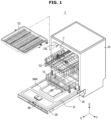
- the dishwasher includes a main body, a washing chamber formed by a tub disposed inside the main body, a storage container disposed inside the washing chamber to store dishes, and a spray unit configured to spray wash water to the storage container.
- the storage container may be usually provided in two or three stages, and the spray unit may be provided in plurality and disposed to correspond to the storage container so as to spray wash water to each place, in which each storage container is disposed.
- the dishwasher may include a washing process, a rinsing process, and a drying process.
- the spray unit may spray wash water, and at the same time, an automatic detergent dispenser may input detergent to the tub. Accordingly, dishes may be washed.
- wash water may be sprayed to remove the detergent.
- moisture remaining in the dishes may be removed.
- the automatic detergent dispenser of the dishwasher may include a storage compartment so as to store various types of detergents, such as powder detergent or liquid detergent, in the storage compartment.
- the storage container is not limited to the shape shown in FIGS. 1 and 2 , and the storage container may not include the upper basket 53 according to the size of the tub 12.
- the storage container may be implemented with the intermediate basket 52 and the lower basket 53.
- the dishwasher 1 may include the washing chamber C, which is a space formed inside the tub 12.
- the washing chamber C may be defined as an inner space of the tub 12.
- the washing chamber C may correspond to a space surrounded by a lower surface 12b, an upper surface 12c and the side surface 12d of the tub 12, and the inner surface 21 of the door 20 when the door 20 closes the tub 12.
- the washing chamber C may refer to a space in which dishes placed in the baskets 51, 52 and 53 are washed by wash water and dried.
- the dishwasher 1 may include a spray device 40 configured to spray wash water.
- the spray device 40 may receive wash water from a sump assembly 70.
- the plurality of spray units 41, 42, and 43 may include a first spray unit 41 arranged under the lower basket 51 in the height direction of the dishwasher 1, a second spray unit 42 arranged under the intermediate basket 52 in the height direction of the dishwasher 1, and a third spray unit 43 arranged above the upper basket 53 in the height direction of the dishwasher 1.
- Each of the plurality of spray units 41, 42, and 43 may be configured to spray wash water while rotating.
- Each of the first spray unit 41, the second spray unit 42, and the third spray unit 43 may be provided to spray wash water while rotating.
- the plurality of spray units 41, 42 and 43 may be referred to as a plurality of spray rotors.
- the first spray unit 41, the second spray unit 42, and the third spray unit 43, respectively, may be referred to as a first spray rotor 41, a second spray rotor 42, and a third spray rotor 43.
- the sump assembly 70 may include a drain pump 60 configured to drain wash water and foreign substances (e.g., food residues) remaining in the sump assembly 70.
- a drain pump 60 configured to drain wash water and foreign substances (e.g., food residues) remaining in the sump assembly 70.
- the sump assembly 70 may pump the collected wash water and supply the wash water to the spray device 40.
- the sump assembly 70 may be connected to the spray device 40 to supply wash water to the spray device 40.
- the sump assembly 70 may be independently connected to the first spray unit 41, the second spray unit 42, and the third spray u7nit 43.
- the sump assembly 70 may be independently connected to connectors connected to the first spray unit 41, the second spray unit 42, and the third spray unit 43.
- the connector may be provided in the shape of a connection port, duct, or the like.
- the dishwasher 1 may include an alternating device (not shown) configured to selectively supply wash water to the spray device 40.
- the alternating device (not shown) may be driven to selectively supply wash water to each connector connected to each of the spray devices 41, 42, and 43.
- the alternating device (not shown) may selectively supply wash water to at least one of a connector connected to the first spray device 41 and a connector connected to the second spray device 42.
- the dishwasher 1 may include a machine room L, which is a space provided below the tub 12.
- the machine room L may be a place in which a component for circulating wash water is disposed.
- the sump assembly 70 may be arranged in the machine room L. Most of the sump assembly 70 may be arranged in the machine room L.
- a volume of the sump assembly 70 a volume of the sump assembly 70 located in the washing chamber C may be less than a volume of the sump assembly 70 located in the machine room L.
- the dishwasher 1 may include an automatic detergent dispenser 1000 configured to input a solid detergent into the tub 12.
- the dishwasher 1 may include a detergent box 90 provided to input not only a solid detergent but also powder detergent or liquid detergent into the tub 12.
- a control device 1900 may control the dishwasher 1 to selectively input the detergent stored in the detergent box 90 into the tub 12 based on the user input obtained from a main control device.
- the information related to the washing mode may include information related to a small amount washing mode in which a small number of dishes is washed or information related to a quick washing mode in which a washing time is minimized.
- the solid detergent means a solid detergent that is formed to have a predetermined shape.
- the solid detergent may have an approximate block shape, and thus the solid detergent may be referred to by various terms such as detergent block and block-type detergent.
- the shape of the solid detergent is not limited to a specific shape or size, and may have various shapes.
- the automatic detergent dispenser 1000 may be provided to allow a plurality of solid detergents to be loaded.
- the automatic detergent dispenser 1000 may be provided to allow one of a plurality of solid detergents to be input into the tub 12 while the dishwasher 1 washes dishes.
- the dishwasher 1 may be provided to wash dishes through a pre-washing operation, a main washing operation, a rinsing operation, and a drying operation.
- the automatic detergent dispenser 1000 may be configured to input a solid detergent into the tub 12 before or at the start of the main washing process.
- the detergent box 90 may be provided to accommodate powder detergent or liquid detergent.
- the detergent box 90 may be provided to allow detergent to be input into the tub 12 while the dishwasher 1 washes dishes.
- the dishwasher 1 may be configured to allow one detergent, which is selected by a user between detergent stored in the detergent box 90 and solid detergents loaded in the automatic detergent dispenser 1000, to be input to the tub 12.
- the automatic detergent dispenser 1000 may be disposed on the inner surface 21 of the door 20.
- the automatic detergent dispenser 1000 may be provided to be coupled to the inner surface 21 of the door 20.
- the detergent box 90 may be disposed on the inner surface 21 of the door 20.
- the automatic detergent dispenser 1000 and the detergent box 90 may be arranged in the third direction Z, which is the vertical direction.
- the automatic detergent dispenser 1000 may be provided to be rotated together with the door 20 by the rotation of the door 20.
- the door 20 When a position in which the door 20 closes the tub 12 is defined as a first position 20A of the door 20, and a position in which the door 20 opens the tub 12 is defined as a second position 20B of the door 20, the door 20 may be configured to open and close the tub 12 by moving between the first position 20A and the second position 20B.
- the second position 20B of the door 20 may be defined as any position among positions at which the door 20 opens the tub 12, and it is appropriate that the second position 20B is a position in which dishes stored in the tub 12 are allowed to be withdrawn to the outside of the tub 12.
- the second position 20B of the door 20 may be a position in which an extension direction of the inner surface 21 of the door 20 corresponds to the first direction X.
- the automatic detergent dispenser 1000 may be interlocked with the door 20 so as to be moved between a first position 1000A of the automatic detergent dispenser 1000 corresponding to the first position 20A of the door 20, and a second position 1000B of the automatic detergent dispenser 1000 corresponding to the second position 20B of the door 20.
- a user can open a storage compartment cover 1140 of the automatic detergent dispenser 1000 and load a plurality of solid detergents into a storage compartment 1200.
- the automatic detergent dispenser 1000 may include a housing 1100.
- the first housing 1110 may be provided to be coupled to the inner surface 21 of the door 20.
- the second housing 1120 may be coupled to the first housing 1110 in the first direction X when the automatic detergent dispenser 1000 is disposed at the first position 1000A.
- the second housing 1120 may form the storage compartment 1200 together with the first housing 1110.
- the second housing 1120 may include a first storage compartment opening 1121 provided to open the storage compartment 1200 to the outside.
- the second housing 1120 may include an inlet 1122 communicating with a seating member 1400 to be described later and configured to allow a solid detergent to be discharged from the automatic detergent dispenser 1000 and introduced into the tub 12.
- components such as the ejector 1300 may be seated on the first housing 1110 and supported by the intermediate housing 1130.
- components such as the ejector 1300 may be seated on the second housing 1120 and supported by the intermediate housing 1130.
- the housing 1100 may include the storage compartment cover 1140 disposed on the second housing 1120 and configured to open and close the storage compartment opening 1121.
- the housing 1100 may include an inlet cover 1150 disposed on the second housing 1120 and configured to open and close the inlet 1122.
- the first housing 1110 may include a control device seating member 1111 disposed in a direction opposite to the direction in which the first housing 1110 is coupled to the second housing 1120, and on which the control device 1900 configured to control the automatic detergent dispenser 1000 is seated.
- control device seating member 1111 may be disposed on an outer side of an inside of the housing 1100 formed by coupling the second housing 1120 to the first housing 1110.
- control device seating member 1111 may be disposed inside the housing 1100 formed by coupling the second housing 1120 to the first housing 1110.
- the transmission member of the seating member door driver 1470 may include a plurality of gears.
- the plurality of gears may transmit a rotational force in one direction to the seating member door 1410.
- the seating member door 1410 may be rotated in one direction by the received rotational force, so as to open the seating member opening 1420 in a state in which the seating member door 1410 closes the seating member opening 1420.
- the plurality of gears may transmit the rotational force in the opposite direction to the seating member door 1410.
- the seating member door 1410 may be rotated in the opposite direction by the received rotational force, so as to close the seating member opening 1420 in a state in which the seating member door 1410 opens the seating member opening 1420.
- the seating member opening 1420 may communicate with the inlet 1122 by the discharge guide 1430.
- One solid detergent located in the seating member inner space 1401 may be discharged from the seating member inner space 1401 through the seating member opening 1420, and then discharged from the seating member opening 1420 to the outside of the automatic detergent dispenser 1000 through the inlet 1122. Accordingly, the solid detergent may be input to the tub 12.
- the seating member 1400 may include the discharge guide 1430 formed between the seating member opening 1420 and the inlet 1122 and provided to guide the movement in which the solid detergent is moved from the seating member opening 1420 to the inlet 1122.
- One solid detergent discharged from the storage compartment 1200 may be temporarily seated on the seating member 1400, and particularly, the solid detergent may be located on the seating surface 1411 of the seating member door 1410 forming the lower surface of the seating member inner space 1401.
- the inlet 1122 may be opened and closed by the inlet cover 1150.
- the inlet cover 1150 may open the inlet 1122 while the solid detergent discharged along the discharge guide 1430 presses the inlet cover 1150.
- the solid detergent may pass through the inlet 1122 while pressing the inlet cover 1150, and then move to the tub 12.
- the solid detergent placed on the seating member door 1410 may be moved downward by gravity, and then discharged to the outside of the seating member inner space 1401 through the seating member opening 1420.
- the storage compartment 1200 may include an intermediate door 1250 configured to open and close the storage compartment outlet 1210.
- the intermediate door 1250 may be configured to prevent a solid detergent, which is loaded into the storage compartment 1200, from being moved to the seating member 1400 by an external force without being discharged from the storage compartment 1200 by the ejector 1300.
- the intermediate door 1250 may be biased in a direction to close the storage compartment outlet 1210.
- the intermediate door 1250 may include an elastic member 1251, and the intermediate door 1250 may be biased toward the storage compartment outlet 1210 by the elastic member 1251 to allow the intermediate door 1250 to close the storage compartment outlet 1210.
- the solid detergent which is pressed by the ejector 1300 and moved to the storage compartment outlet 1210 among the plurality of solid detergents loaded into the storage compartment 1200, may open the intermediate door 1250 by pressing the intermediate door 1250. As the intermediate door 1250 is opened, the solid detergent may be moved to the seating member 1400 through the storage compartment outlet 1210.
- the solid detergent may be blocked by the intermediate door 1250 and thus the solid detergent may not pass through the storage compartment outlet 1210 and may not be discharged from the storage compartment 1200.
- the storage compartment outlet 1210 may be connected to the tub 12 through the seating member 1400 without being directly connected to the tub 12.
- the water remaining in the tub 12 may flow into the storage compartment 1200 through the storage compartment outlet 1210, and thus the plurality of solid detergents loaded inside the storage compartment 1200 may be damaged or deformed by the water.
- the storage compartment outlet 1210 may be provided to be bypassed to the tub 12 through the seating member 1400 without being directly connected to the tub 12.
- the seating member 1400 may open the seating member opening 1420 to allow the seating member inner space 1401 to communicate with the tub 12.
- the seating member door 1410 may close the seating member opening 1420 at a stage when the solid detergent is not input into the tub 12, so as to minimize a flow of water, which remains in the tub 12, into the seating member inner space 1401.
- the seating member sensor 1440 may be provided as a position sensor.
- the seating member sensor 1440 may include an optical sensor.
- the control device 1900 may receive information related to whether the solid detergent is loaded in the storage compartment 1200, whether the soiled detergent is seated on the seating member 1400 after the ejector 1300 is driven in a state in which the solid detergent is loaded in the storage compartment 1200, and whether the solid detergent is discharged from the seating member 1400 after the solid detergent is seated on the seating member 1400, and control the automatic detergent dispenser 1000 based on the received information.
- the control device 1900 may be configured to communicate with the main control device of the dishwasher 1 and configured to allow the controller to control the dishwasher 1 based on the received information.
- control device 1900 may allow the ejector 1300 to be driven again to move the solid detergent to the seating member 1400.
- the control device 1900 may communicate with the main control device, and the controller may control the dishwasher 1 not to perform the washing process of the dishwasher 1 based on a communication value.
- the display may be implemented as a display positioned on the main body 10 of the dishwasher 1.
- the display may be implemented in a separate device configured to communicate with the dishwasher 1.
- the control device 1900 may determine that the solid detergent is discharged from the seating member 1400 and then input to the tub 12, and the control device 1900 may control the automatic detergent dispenser 1000 based on the determination.
- the control device 1900 may communicate with the main control device, and the controller may control the dishwasher 1 to perform the washing process of the dishwasher 1 based on the communication value.
- the control device 1900 may be configured to identify all of the above situations, and thus it is possible to minimize the number of additional sensors configured to detect a position of a solid detergent. That is, even when a position sensor, which is configured to additionally detect a position of the solid detergent, is not placed to the storage compartment 1200 or the discharge guide 1430, the control device 1900 may be configured to determine all of whether the solid detergent is located in the storage compartment 1200, or whether the solid detergent is located in the seating member inner space 1401 or whether the solid detergent is located in the outside of the seating member 1400, by placing the seating member sensor 1440 on the seating member 1400. This will be described later in detail.
- the storage compartment 1200 may be provided in plurality.
- two storage compartments 1200 may be provided.
- the storage compartment 1200 disposed on the left side in the second direction Y with respect to FIG. 8 is defined as a first storage compartment 1200
- a storage compartment 1200' disposed on the right side is defined as a second storage compartment 1200'
- a configuration of the first storage compartment 1200 is defined as a first configuration
- a configuration of the second storage compartment 1200' is defined as a second configuration
- the intermediate door 1250 of the first storage compartment 1200 is defined as a first intermediate door 1250 and an intermediate door 1250' of the second storage compartment 1200' is defined as a second intermediate door 1250'.
- an ejector configured to discharge a solid detergent stored in the first storage compartment 1200 is defined as a first ejector 1300
- an ejector configured to discharge a solid detergent stored in the second storage compartment 1200' is defined as a second ejector 1300'.
- a holder 1500 disposed inside the first storage compartment 1200 is defined as a first holder 1500
- a holder 1500 disposed inside the second storage compartment 1200' is defined as a second holder 1500'.
- the first and second storage compartments 1200 and 1200' may be provided to be spaced apart from each other in the second direction Y.
- the first and second storage compartments 1200 and 1200' include long sides extending in the third direction Z when the automatic detergent dispenser 1000 is disposed at the first position 1000A, respectively. Accordingly, when the first and second storage compartments 1200 and 1200' are provided to be spaced apart from each other in the second direction Y, the first and second storage compartments 1200 and 1200' may be efficiently arranged inside the automatic detergent dispenser 1000.
- first and second storage compartments 1200 and 1200' Due to the first and second storage compartments 1200 and 1200', a user can load a large number of solid detergents into the automatic detergent dispenser 1000 at one time.
- the seating member 1400 may be disposed between the first storage compartment 1200 and the second storage compartment 1200' in the second direction Y.
- the first storage compartment 1200 may be provided to communicate with the seating member 1400 as described above, and the second storage compartment 1200' may also be provided to communicate with the seating member 1400.
- first and second storage compartments 1200 and 1200' may communicate with the tub 12 through a single seating member 1400 arranged between the first storage compartment 1200 and the second storage compartment 1200' in the second direction Y.
- the automatic detergent dispenser 1000 may increase in volume in the second direction Y due to the plurality of seating members.
- the first and second storage compartments 1200 and 1200' may communicate with each other through a single seating member 1400 as described above, and thus it is possible to minimize the length of the automatic detergent dispenser 1000 in the second direction Y.
- the first cam member 1310 may be provided to be rotated in a clockwise direction by interlocking with the first driving motor 1320 and the first transmission member 1330.
- the second storage compartment 1200' may include a second penetration member 1221' formed on the second lower surface 1220' of the second storage compartment 1200' and provided to allow a second pressing portion 1312a' to be moved from the outside of the second storage compartment 1200' to the inside of the second storage compartment 1200'.
- the second penetration member 1221' may be provided to extend not only to the second lower surface 1220' of the second storage compartment 1200' but also to the lower side of a second right surface 1230' and a second left surface 1240' of the second storage compartment 1200'.
- the second pressing portion 1312a' may be rotated by the rotation of the second cam member 1310' and moved into the second storage compartment 1200' through the lower side of the second right surface 1230' and the second penetration member 1221' of the second lower surface 1220', and then moved to the outside of the second storage compartment 1200' through the lower side of the second left surface 1240' and the second penetration member 1221' of the second lower surface 1220'.
- the second pressing portion 1312a' may be provided to be rotated while pressing the solid detergent seated on the second lower surface 1220', so as to allow the solid detergent to be moved to the left side.
- the first rotating axis 1313 of the first cam member 1310 may be disposed between the first left surface 1240 and the first right surface 1230 of the first storage compartment 1200 in the second direction Y.
- the first rotating axis 1313 of the first cam member 1310 may be disposed at the center of the left surface 1240 and the right surface 1230 of the first storage compartment 1200 in the second direction Y.
- a second rotating axis 1313' of the second cam member 1310' may be disposed between the second left surface 1240' and the second right surface 1230' of the second storage compartment 1200' in the second direction Y.
- the second rotating axis 1313' of the second cam member 1310' may be disposed at the center of the second left surface 1240' and the second right surface 1230' of the second storage compartment 1200' in the second direction Y.
- the first and second pressing portions 1312a and 1312a' may pass through the first and second penetration members 1221 and 1221' with a predetermined length or less of the first and second pressing portions 1312a and 1312a' and thus it is difficult for the first and second pressing portions 1312a and 1312a' to stably support the solid detergent, in a section in which the first and second pressing portions 1312a and 1312a' pass through the first and second penetration members 1221 and 1221' by the rotation of the first and second cam members 1310 and 1310'.
- the first and second pressing portions 1312a and 1312a' may pass through the first and second penetration members 1221 and 1221' with a predetermined length or less of the first and second pressing portions 1312a and 1312a' and thus it is difficult for the first and second pressing portions 1312a and 1312a' to stably support the solid detergent loaded into the first and second storage compartments 1200 and 1200'.
- first and second rotating axes 1313 and 1313' of the first and second cam members 1310 and 1310' may be respectively disposed at the center of the first and second storage compartments 1200 and 1200' in the second direction Y in order that the first and second pressing portions 1312a and 1312a' pass through the first and second penetration members 1221 and 1221' and are rotated with a predetermined length or more of the first and second pressing portions 1312a and 1312a', in a section in which the first and second pressing portions 1312a and 1312a' enter or exit the first and second storage compartments 1200 and 1200' through the first and second penetration members 1221 and 1221'.
- the volume of the automatic detergent dispenser 1000 in the second direction Y may increase. Accordingly, it is appropriate that the first and second rotating axes 1313 and 1313' of the first and second cam members 1310 and 1310' are respectively disposed at the center of the first and second storage compartments 1200 and 1200' in the second direction Y.
- the first ejector 1300 and the second ejector 1300' may be provided to be driven in a mirror-symmetrical direction in the second direction Y with respect to the seating member 1400.
- the first cam member 1310 and the second cam member 1310' may be configured to be rotated in opposite directions to each other so as to be mirror symmetrical about the seating member 1400.
- the first ejector 1300 and the second ejector 1300' may be provided to be driven in a mirror-symmetrical direction in the second direction Y with respect to the seating member 1400.
- a width L1 of the first storage compartment 1200 in the second direction Y may be substantially the same as a width L1 of the second storage compartment 1200'.
- the width L1 of the first and second storage compartments 1200 and 1200' in the second direction Y may substantially correspond to a width L3 of the seating member 1400.
- the solid detergent When the solid detergent is discharged from the first and second storage compartments 1200 and 1200 in a state in which the width L3 of the seating member 1400 in the second direction Y is excessively less than the width L1 of the first and second storage compartments 1200 and 1200', the solid detergent may be stuck in the seating member inner space 1401 without being seated on the seating member door 1410.
- the volume of the seating member 1400 in the second direction Y may increase more than necessary and thus the volume of the automatic detergent dispenser 1000 in the second direction Y may increase more than necessary.
- the width L3 of the seating member 1400 may have a length corresponding to the width L1 of the first and second storage compartments 1200 and 1200' having a cross-sectional area S in accordance with the size of the solid detergent, in the second direction Y.
- FIG. 8 is a view illustrating a state in which some components of the automatic detergent dispenser of the dishwasher according to an embodiment are removed
- FIG. 9 is a view illustrating a state in which a solid detergent loaded in a first storage compartment of FIG. 8 is discharged from the first storage compartment
- FIG. 10 is a view illustrating a state in which the solid detergent of FIG. 9 is seated on a seating member
- FIG. 11 is a view illustrating a state in which the solid detergent of FIG. 10 is discharged from the automatic detergent dispenser
- FIG. 12 is a view illustrating a state in which a solid detergent loaded in a second storage compartment of FIG. 8 is discharged from the second storage compartment.
- control device 1900 may control the first ejector 1300 or the second ejector 1300' to allow one of the plurality of solid detergents stacked in one of the first storage compartment 1200 and the second storage compartment 1200' to be moved to the seating member 1400.
- control device 1900 may control the first ejector 1300 to allow the first cam member 1310 to be rotated clockwise.
- control device 1900 may control the second ejector 1300' to allow the second cam member 1310' to be rotated clockwise.
- the control device 1900 may transmit the information that no solid detergent is detected to the main control device.
- the controller may control the dishwasher 1 to allow the dishwasher 1 not to perform the pre-washing operation of the washing process based on the communicated value. This is because, in some cases, a user can open the door 20 to load the solid detergent into the automatic detergent dispenser 1000. Accordingly, the controller may control the dishwasher 1 not to start the washing process itself when no solid detergent is placed in the seating member 1400.
- control device 1900 may control the automatic detergent dispenser 1000 to allow the solid detergent to be automatically input into the tub 12 in response to the dishwasher 1 performing the washing process.
- the seating member sensor 1440 may fail to detect the solid detergent even after the control device 1900 controls the first ejector 1300 to be driven twice.
- control device 1900 may control the second ejector 1300' to be driven.
- the feature of driving the second ejector 1300' by the control device 1900 is the same as the feature of driving the first ejector 1300 by the control device 1900, and thus a description thereof will be omitted.
- the automatic detergent dispenser 1000 may include a storage compartment including a long side extending in the second direction Y, which is the left and right direction of the dishwasher 1.
- a plurality of solid detergents may be stacked and loaded in the second direction Y inside the storage compartment.
- the automatic detergent dispenser 1000 may include a holder configured to move the plurality of solid detergents, which is stacked in the second direction Y inside the storage compartment, to the second direction Y.
- the holder may include an elastic member, and thus the holder may move the plurality of solid detergents to the second direction Y toward a cam member of an ejector.
- the cam member may press one of the plurality of solid detergents to be discharged to the outside of the storage compartment.
- the solid detergent may be discharged to a direction perpendicular to the second direction Y and then moved to the lower side of the storage compartment.
- One solid detergent discharged to the outside of the storage compartment may be introduced into the tub 12 through a seating member or the like.
- the automatic detergent dispenser 1000 when the automatic detergent dispenser 1000 is at the first position 1000A, the plurality of solid detergents is stacked and loaded in the third direction Z, which is the vertical direction, inside the storage compartments 1200 and 1200'.
- the plurality of solid detergents are moved from the top to the bottom along the third direction Z inside the storage compartments 1200 and 1200', and are discharged to the outside of the storage compartments 1200 and 1200' starting from a solid detergent located at a lower position.
- the stacking direction of the plurality of solid detergents is not limited by the term "third direction".
- the stacking direction of the plurality of solid detergents may be referred to as a "first direction” as needed, and even in this case, the term “first direction” may represent the Z direction shown in the drawings according to an embodiment of the disclosure (it is assumed that the automatic detergent dispenser 1000 is at the first position 1000A) and the like.
- the automatic detergent dispenser 1000 according to an embodiment of the present disclosure will be made in detail on the first storage compartment 1200, the first ejector 1300, and the first cam member 1310.
- the following description may be equally applied to the second storage compartment 1200', the second ejector 1300', and the second cam member 1310'. Accordingly, in the following description, detailed configurations and operations of the cam member according to an embodiment of the disclosure will be described by referring to the first storage compartment 1200, the first ejector 1300, the first cam member 1310, and the like as the storage compartment 1200, the ejector 1300, the cam member 1310, and the like.
- FIG. 13 is a view illustrating a cam member of the automatic detergent dispenser of the dishwasher according to an embodiment
- FIG. 14 is an enlarged view of a part of FIG. 9
- FIG. 15 is a view illustrating a state in which the solid detergent of FIG. 8 moves inside the storage compartment
- FIG. 16 is a view illustrating a state in which the cam member rotates in a direction opposite to that shown in FIGS. 10 to 14 in the automatic detergent dispenser of the dishwasher according to an embodiment.
- the automatic detergent dispenser 1000 may include an automatic detergent dispenser 1000 disposed on the door 20 and configured to input a solid detergent to the inside of the tub.
- the automatic detergent dispenser 1000 may include a storage compartment 1200 into which a plurality of solid detergents are loaded, and a cam member 1310 provided to move one of the plurality of solid detergents to the outside of the storage compartment 1200.
- the cam member 1310 may transport one solid detergent among the solid detergents inside the storage compartment 1200 to the outside of the storage compartment 1200.
- the cam member 1310 may be referred to as a "transporting member”.
- the ejector 1300 may include a transporting member that transports a solid detergent inside the storage compartment 1200 to the outside of the storage compartment 1200 by a structure other than a cam structure.
- the transporting member of the ejector 1300 may transport a solid detergent from the inside of the storage compartment 1200 to the outside through a translational motion.
- the transporting member 1310 of the ejector 1300 has a cam structure as shown in the drawings, and for the sake of convenience of description, a "transporting member 1310" is referred to as a "cam member 1310".
- the storage compartment 1200 may be provided to allow a plurality of solid detergents to be stacked and loaded in the third direction Z as described above.
- the cam member 1310 may be provided at a side of the storage compartment 1200 in the third direction Z. Specifically, the cam member 1310 may be provided at a lower side of the storage compartment 1200 when the automatic detergent dispenser 1000 is in the first position 1000A. Accordingly, the cam member 1310 may be provided to move one solid detergent located at the lowest position of the storage compartment 1200 among the plurality of solid detergents to the outside of the storage compartment 1200. However, alternatively, the cam member 1310 may also be provided at an upper side of the storage compartment 1200 as described above.
- the automatic detergent dispenser 1000 may include a holder 1500 provided to maintain a stacked state of the plurality of solid detergents inside the storage compartment 1200.
- the holder 1500 may be located in the third direction Z of the plurality of solid detergents inside the storage compartment 1200, and may be provided to press the plurality of solid detergents in the third direction Z.
- the holder 1500 when a direction in which the plurality of solid detergents are stacked while the automatic detergent dispenser 1000 is located in the first position 1000A is defined as a direction from an upper side of the storage compartment 1200 to a lower side of the storage compartment 1200, the holder 1500 may be referred to as being located at a side in the stacking direction with respect to the plurality of solid detergents. In addition, the holder 1500 may be referred to as being provided to press the plurality of solid detergents in a direction opposite to the stacking direction.
- the cam member 1310 may be referred to as being located at a side in a direction opposite to the stacking direction of the plurality of solid detergents with respect to the storage compartment 1200. That is, the holder 1500 may move the plurality of solid detergents loaded in the storage compartment 1200 toward the cam member 1310. The cam member 1310 may be provided to discharge one of the plurality of solid detergents pressed by the holder 1500 from the storage compartment 1200.
- the cam member 1310 may be rotatably provided with respect to the storage compartment 1200. In other words, the cam member 1310 may be rotatably provided with respect to the housing 1100.
- the cam member 1310 may be provided to, through rotation, press one solid detergent toward the outside of the storage compartment 1200. Alternatively, the cam member 1310 may be provided to, through rotation, guide a movement of the plurality of solid detergents in parallel to the third direction Z inside the storage compartment 1200.
- a rotational direction in which the cam member 1310 rotates to press one solid detergent toward the outside of the storage compartment 1200 or to guide a movement of a plurality of solid detergents in parallel to the third direction Z inside the storage compartment 1200 may be defined as the first rotational direction R1.
- the first rotational direction R1 may be a direction in which the first cam member 1310 rotates clockwise. Conversely, referring to FIGS. 13 to 17 , the first rotational direction R1 may be a direction in which the second cam member 1310' rotates counterclockwise.
- the cam member 1310 may be rotatably provided with respect to the rotating axis 1313.
- the rotating axis 1313 of the cam member 1310 may be disposed at a side in the third direction Z with respect to the storage compartment 1200.
- the rotating axis 1313 of the cam member 1310 may be positioned below the storage compartment 1200.
- the cam member 1310 may be rotatably provided at a lower side of the storage compartment 1200.
- the cam member 1310 may be provided to discharge one solid detergent adjacent to the rotating axis 1313 among the plurality of solid detergents from the storage compartment 1200.
- a hub portion 1311 may be disposed at a lower side of the storage compartment 1200.
- the automatic detergent dispenser 1000 may include power supply devices 1320 and 1330 that supply power to the cam member 1310 so that the cam member 1310 is rotatable.
- the power supply devices 1320 and 1330 may be provided to supply power to the rotating axis 1313 of the cam member 1310.
- the ejector 1300 may include the driving motor 1320 and the transmission member 1330 as components of the power supply devices 1320 and 1330.
- the driving motor 1320 may generate rotational force to drive the cam member 1310
- the transmission member 1330 may transmit the rotational force generated by the driving motor 1320 to the rotating axis 1313 of the cam member 1310.
- the transmission member 1330 may include a plurality of gears, and the plurality of gears may include various types of gears, such as a spur gear, a worm gear, and a bevel gear.
- the cam member 1310 may include a power transmission portion 1314 provided to receive power from the power supply devices 1320 and 1330.
- the power transmission portion 1314 may be formed in the shape of a gear including teeth, and may be provided to mesh with the gear of the transmission member 1330.
- the power transmission portion 1314 may be formed in the shape of a gear centered on the rotating axis 1313. Accordingly, the cam member 1310 may receive power from the power supply devices 1320 and 1330 and may be provided to be rotatable around the rotating axis 1313.
- the cam member 1310 may receive rotational force through various configurations.
- the transmission member 1330 may not include a plurality of gears, but may include only a single gear connected to the driving motor 1320 and meshing with the power transmission portion 1314 of the cam member 1310 to transmit rotational force to the cam member 1310.
- the power transmission portion 1314 of the cam member 1310 may not be provided in the shape of a gear, more specifically, may have a configuration in which the rotating axis 1313 is connected to the center of one gear among a plurality of gears of the transmission member 1330 to receive rotational force.
- the body portion 1312 may be provided to allow one of the plurality of solid detergents stacked inside the storage compartment 1200 to be pressed in a direction different from the third direction Z by the pressing portion 1312a.
- the body portion 1312 may be provided to allow one solid detergent to be pressed in a second direction Y, which is a direction perpendicular to the third direction Z, by the pressing portion 1312a.
- the pressing portion 1312a obliquely extends from the hub portion 1311 only in the first rotational direction R1 with respect to the radial direction of the hub portion 1311.
- the above described issue that one solid detergent pressed by the pressing portion 1312a is lifted upward may not occur.
- a portion of the pressing portion 1312a that is in contact with the solid detergent may only be a portion disposed outside the radial direction, and thus the efficiency of one solid detergent being pressed by the pressing portion 1312a may decrease.
- the pressing portion 1312a may include a first portion 1312aa and a second portion 1312ab extending in different directions.
- the pressing portion 1312a may include the first portion 1312aa formed to extend from the hub portion 1311 and the second portion 1312ab formed to bend and extend from the first portion 1312aa.
- the second portion 1312ab may be formed to bend from one end of the first portion 1312aa and extend in the first rotational direction R1. That is, the second portion 1312ab may be formed to extend from the first portion 1312aa in a direction toward the one solid detergent when the pressing portion 1312a presses one solid detergent.
- the second portion 1312ab may apply a downward external force to the one solid detergent, and may prevent the one solid detergent from being lifted upward when pressed.
- the second portion 1312ab may prevent the one solid detergent from being lifted upward.
- the first portion 1312aa may be formed to obliquely extend from the hub portion 1311 in a direction opposite to the first rotational direction R1 with respect to the radial direction of the hub portion 1311.
- the first portion 1312aa may be formed to extend from the hub portion 1311 in a direction away from the one solid detergent when the pressing portion 1312a may press the one solid detergent.
- the one solid detergent may be sufficiently pressed not only by the second portion 1312ab but also by the first portion 1312aa.
- the second portion 1312ab may be set to bend at a larger angle with respect to the first portion 1312aa, so that the solid detergent may be more effectively prevented from being lifted up when pressed.
- the pressing portion 1312a may be formed to include a concave shape by the first portion 1312aa and the second portion 1312ab.
- a concave-convex shape (not shown), a rib (not shown) or the like may be formed on the pressing portion 1312a to effectively prevent the solid detergent from slipping when pressed.
- the first portion 1312aa may not easily come in contact with one solid detergent, and thus the solid detergent may not be sufficiently pressed by the first portion 1312aa.
- the second portion 1312ab may need to bend at a smaller angle with respect to the first portion 1312aa so as to extend toward the first rotational direction R1.
- the first portion 1312aa may be formed to extend from the hub portion 1311 by a length greater than or equal to an extension length of the second portion 1312ab from the first portion 1312aa. Furthermore, preferably, the extension length of the first portion 1312aa may be formed to be longer than the extension length of the second portion 1312ab.
- the pressing portion 1312a may extend in various directions and may be formed to have various shapes.
- the pressing portion 1312a may be formed to have a convex shape toward the first rotational direction R1.
- the pressing portion 1312a may be formed to extend in a constant direction and have an overall flat shape.
- the pressing portion 1312a may protrude from the hub portion 1311 to have a length substantially corresponding to a length of one solid detergent. More specifically, in the pressing portion 1312a, the distance between one end of the first portion 1312aa adjacent to the hub portion 1311 and one end of the second portion 1312ab opposite to the first portion 1312aa may be provided to correspond to the solid detergent. The pressing portion 1312a may protrude to correspond approximately to the height h of one solid detergent D (see FIG. 7 ).
- the difference between the distance from the rotating axis 1313 to the outer end of the pressing portion 1312a and the distance from the rotating axis 1313 to the inner end of the pressing portion 1312a (or to the hub portion 1311) may correspond approximately to the height h of one solid detergent D.
- the difference between the maximum distance to a second cam region 1310A2 of the cam member 1310 and the distance to a first cam region 1310A1 may correspond approximately to the height h of one solid detergent D.
- the pressing portion 1312a may be formed to press one solid detergent at a position higher than or equal to approximately at least a middle height of the one solid detergent. That is, the pressing portion 1312a may protrude to have a length greater than or equal to approximately the middle position of the height h of one solid detergent D.
- the pressing portion 1312a may be provided with a length suitable for sufficiently pressing one solid detergent without pressing two or more solid detergents due to having an excessively long length.
- the solid detergent may have various sizes depending on the components, functions, or manufacturing companies of the solid detergent, it is not that the pressing portion 1312a has a length exactly corresponding to one solid detergent or greater than or equal to a middle position of one solid detergent.
- the body portion 1312 may press one solid detergent among a plurality of solid detergents stacked and loaded inside the storage compartment 1200 to move the one solid detergent to the outside of the storage compartment 1200.
- the hub portion 1311 and the body portion 1312 may be integrally formed with each other.
- the cam member 1310 may be formed as one part.
- the hub portion 1311 and the body portion 1312 may be components conceptually defining respective portions of the cam member 1310 formed as one part.
- the hub portion 1311 and the body portion 1312 are described assuming that the hub portion 1311 is defined as a disk-shaped component with only a portion of the outer rim exposed, and the body portion 1312 is defined a component radially extending from a portion of the outer rim of the hub portion 1311, but the configuration of the hub portion 1311 and the body portion 1312 is not limited to the definitions.
- the hub portion and the body portion may not be integrally formed with each other, and the hub portion formed to have a smaller radius than the hub portion 1311 shown FIG. 13 and the body portion provided to cover the entire outer rim of the hub part may be coupled to each other to form a cam member.
- the body portion may also be defined as a component extending from a portion of the outer rim of the hub portion, and the hub portion may also be defined as a component whose outer rim is partially exposed to the outside due to absence of the body portion at another portion of the outer rim.
- the cam member includes a disk-shaped hub portion having a constant radius from the rotating axis and a pressing portion protruding radially from the hub portion and configured to press one solid detergent, in which the pressing portion may be formed to radially protrude from a very narrow portion of the outer rim of the hub portion, allowing the rest of the outer rim of the hub portion to be exposed to the outside.
- an effect of moving one of the plurality of solid detergents stacked inside the storage compartment 1200 to the outside of the storage compartment 1200 may be provided.
- the plurality of solid detergents remaining inside the storage compartment 1200 after one solid detergent is discharged may not be properly supported by the cam member due to the steep step difference between the body portion or the pressing portion and the hub portion in a process in which the cam member is rotated, and thus may be rapidly moved in the third direction Z.
- the plurality of solid detergents remaining inside the storage compartment 1200 may be fallen to the bottom of the storage compartment 1200.
- noise and vibration may be generated due to a collision between the plurality of solid detergents and the support surface 1222 of the storage compartment 1200, the life span of the product may be reduced due to a damage to parts, the solid detergent may be damaged, or the stacked state of the plurality of the solid detergent may be disturbed.
- the cam member 1310 may be provided to allow the plurality of solid detergents seated on the outer rim to be moved inside the storage compartment 1200 in parallel with the third direction Z in a stepwise and/or gradual manner as the cam member 1310 rotates in the first rotational direction R1.
- the cam member 1310 may include a plurality of cam regions divided in the first rotational direction R1 on the outer rim of the cam member 1310.
- the plurality of cam regions may include a first cam region 1310A1 and a second cam region 1310A2 positioned at a side of the first cam region 1310A1 in the first rotational direction R1.
- the second cam region 1310A2 may have a length radially extending from the rotating axis 1313 that tends to increase along the first rotational direction R1.
- a portion of the second cam region 1310A2 in contact with the plurality of solid detergents inside the storage compartment 1200 may have a length extending from the rotating axis 1313 that tends to decrease. That is, the second cam region 1310A2 may be formed to guide the solid detergent in the storage compartment 1200 in a direction toward the rotating axis 1313 of the transporting member 1310 during rotation in the first rotational direction R1. Accordingly, the solid detergent stacked inside the storage compartment 1200 may descend in the third direction Z in a stepwise manner.
- the second cam region 1310A2 may include a concave area 1310CA that is concavely recessed inwardly in the radial direction of the cam member 1310.
- the concave area 1310CA may be disposed between the plurality of peak areas 1310PA.
- the concave area 1310CA may be concavely formed on the outer circumferential surface of the body portion 1312.
- the distances of the plurality of solid detergents seated on the second cam region 1310A2 from the rotating axis 1313 of the cam member 1310 may decrease in a stepwise manner.
- the second rotational direction R2 may be a direction in which the first cam member 1310 rotates counterclockwise. Conversely, based on FIGS. 13 to 16 , the second rotational direction R2 may be a direction in which the second cam member 1310' rotates clockwise.
- control device 1900 may recognize that the solid detergent has not been discharged from the storage compartment 1200 and not moved to the seating portion 1400 despite the rotation of the cam member 1310.
- control device 1900 may, upon sensing by the seating member sensor 1440 that the solid detergent has not been seated on the seating member 1400 after the cam member 1310 is driven to rotate in the first rotational direction R1, receive a signal output from the seating member sensor 1440, and based on the received signal, recognize that the solid detergent has not been discharged from the storage compartment 1200.
- control device 1900 may recognize that the solid detergent has not been discharged from the storage compartment 1200 in various ways.
- the control device 1900 may identify that the solid detergent has been caught inside the storage compartment 1200 or between the intermediate door 1250 and the storage compartment 1200.
- control device 1900 may, based on a power consumption of the driving motor 1320 increasing to a value greater than or equal to a reference power consumption (a power consumption required for driving of the driving motor 1320 at normal times) or an increasing load of the driving motor 1320 in a process of rotating the cam member 1310 in the first rotational direction R1, identify that a solid detergent has been caught in the storage compartment 1200.
- a reference power consumption a power consumption required for driving of the driving motor 1320 at normal times
- control device 1900 may, based on recognizing that the solid detergent has not been discharged from the storage compartment 1200 despite the rotation of the cam member 1310 in the first rotational direction R1, identify that the solid detergent has been caught in the storage compartment 1200.
- control device 1900 may control driving of the ejector 1300 such that the cam member 1310 rotates in the second rotational direction R2.
- the plurality of peak areas 1310PA protruding in the radial direction of the cam member 1310 may press the lower surface of the caught solid detergent in the third direction Z.
- the plurality of peak areas 1310PA may press the caught solid detergent in a direction from the outside of the storage compartment 1200 to the inside of the storage compartment 1200.
- the solid detergent caught in the storage compartment 1200 may be released, and then the cam member 1310 may rotate again in the first rotational direction R1 to press one solid detergent and discharge the one solid detergent to the outside of the storage compartment 1200.
- the control device 1900 may, upon recognizing that there is no solid detergent discharged from the storage compartment 1200 even after performing the above process, identify that the solid detergent is still caught inside the storage compartment 1200, or may identify that there is no solid detergent loaded into the storage compartment 1200.
- the configuration of the plurality of cam regions provided on the outer rim of the cam member 1310 is not limited to the above description, and the cam member 1310 may be formed to have an outer circumferential surface in a variety of shapes different from those shown in FIGS. 13 to 16 .
- FIG. 17 is a view illustrating a state in which the storage compartment is closed by an intermediate door after the solid detergent of FIG. 9 is discharged from the first storage compartment.
- the intermediate door 1250 may be provided to close the storage compartment outlet 1210.
- one solid detergent pressed by the cam member 1310 and moved to the storage compartment outlet 1210 may open the intermediate door 1250 while pressing the intermediate door 1250, and as the intermediate door 1250 is opened, may be moved to the seating member 1400 through the storage compartment outlet 1210.
- the intermediate door 1250 may be provided to immediately close the storage compartment outlet 1210.
- the intermediate door 1250 may be biased toward the storage compartment outlet 1210 by the elastic member 1251 such that the intermediate door 1250 closes the storage compartment outlet 1210.
- the intermediate door 1250 may be provided to restrict a movement of the solid detergent inside the storage compartment 1200 to the outside of the storage compartment 1200 by another external force, rather than being discharged by pressing of the cam member 1310.
- the pressing portion 1312a of the cam member 1310 may be provided such that a distance between one end of the pressing portion 1312a in the radial direction of the hub portion 1311 and the rotating axis 1313 of the cam member 1310 is greater than or equal to a distance between the storage compartment outlet 1210 and the rotating axis 1313.
- the pressing portion 1312a may be elongated to pass through the storage compartment outlet 1210 according to the rotation of the cam member 1310.
- the pressing portion 1312a may pass through the storage compartment outlet 1210 immediately after one solid detergent is moved to the seating member 1410 as shown in FIG. 17 .
- the intermediate door 1250 may include a door insertion portion 1250a into which at least a portion of the pressing portion 1312a is insertable, to rapidly close the storage compartment outlet 1210.
- the pressing portion 1312a located in a position passing through the storage compartment outlet 1210 by rotation, may be inserted into the door insertion portion 1250a, and the intermediate door 1250 may be prevented from interfering with the pressing portion 1312a during a process of being closed.
- the door insertion portion 1250a may extend to one end of the intermediate door 1250 in the third direction Z.
- the pressing portion 1312a inserted into the door insertion portion 1250a may be provided to rotate in the first rotational direction R1, and reach the one end of the intermediate door 1250 in the third direction Z, escaping from the door insertion portion 1250a.
- the thickness of the pressing portion 1312a in the first direction X may be smaller than the width of the door insertion portion 1250a in the first direction X.
- FIG. 18 is a view illustrating a state in which some components of the automatic detergent dispenser of the dishwasher according to an embodiment are removed.
- FIG. 18 a detergent automatic detergent dispenser of a dishwasher according to an embodiment will be described.
- components identical to those shown in FIGS. 1 to 17 may be given the same reference numerals, and descriptions thereof may be omitted.
- the automatic detergent dispenser 1000 of the dishwasher 1 may include cam members 2310 and 2310' rotatably provided at one side of the storage compartments 1200 and 1200'.
- the cam members 2310 and 2310' may include a first cam member 2310 disposed on the left side and a second cam member 2310' disposed on the right side with reference to FIG. 18 .
- the first cam member 2310 and the second cam member 2310' may be configured to correspond to each other.
- the first cam member 2310 may be referred to as a cam member.
- the cam member 2310 may be provided to be rotatable around a rotating axis 2313 located at a side of the storage compartment 1200 in the third direction Z.
- the cam member 2310 may include a power transmission portion 2314 provided to receive rotational force from the power supply devices 1320 and 1330.
- the cam member 2310 may include a hub portion 2311 provided to be rotatable around the rotating axis 2313 and a body portion 2312 provided to be rotatable together with the hub portion 2311 and formed to radially extend from a portion of an outer rim of the hub portion 2311.
- the body portion 2312 may include a pressing portion 2312a provided to rotate in the first rotational direction R1 to press one solid detergent toward the outside of the storage compartment 1200.
- the pressing portion 2312a may be provided at one end of the body portion 2312 in the first rotational direction R1.
- the pressing portion 2312a may be formed to extend only in a constant direction from the hub portion 2311, for example, in a radial direction of the hub portion 2311. However, it is not limited thereto, and as an example, the pressing portion 2312a may be formed to have a concavely recessed shape.
- the body portion 2312 may be formed to include a shape in which a length extending from the hub portion 2311 gradually increases along the first rotational direction R1.
- the body portion 2312 may be formed to have a shape in which a distance between an outer rim of the body portion 2312 and the rotating axis 2313 gradually increases along the first rotational direction R1.
- the body portion 2312 may be formed to include a smooth curved surface.
- control device 1900 may control the automatic detergent dispenser 1000 to allow the first ejector 1300 to be driven.
- the guide rail 1290 provided to guide the movement of the holder 1500 may be disposed on the support wall 1271.
- the holder 1500 may be translated in the third direction Z by being guided by the guide rail 1290 disposed on the support wall 1271 and the guide rail disposed on one surface, on which the adjusting member 1270 is not disposed, of the right surface 1230 or the left surface 1240.
- the storage compartment 1200 may include an adjusting member detection sensor configured to detect a position of each of the support walls 1271 and 1271'.
- the adjusting member detection sensor may detect a position in which the support wall 1271 of the first storage compartment 1200 and the support wall 1271' of the second storage compartment 1200' are disposed, and the control device 1900 may be configured to recognize the type of solid detergent loaded in the first storage compartment 1200 and the type of the solid detergent loaded in the second storage compartment 1200' based on the detected value.
- the cam members 1310 and 2310 may be provided to be rotatable about a rotating axis in a direction parallel to the third direction Z. Even when a plurality of solid detergents are stacked in the third direction Z in the storage compartment 1200, the cam members 1310 and 2310 may be disposed at the lower side of the storage compartment 1200 in the third direction Z, The cam members 1310 and 2310 may be provided to press one solid detergent to the outside of the storage compartment 1200 while rotating around the rotating axis in a direction parallel to the third direction Z.
Landscapes
- Chemical & Material Sciences (AREA)
- Life Sciences & Earth Sciences (AREA)
- Engineering & Computer Science (AREA)
- Chemical Kinetics & Catalysis (AREA)
- Oil, Petroleum & Natural Gas (AREA)
- Wood Science & Technology (AREA)
- Organic Chemistry (AREA)
- Washing And Drying Of Tableware (AREA)
Applications Claiming Priority (2)
| Application Number | Priority Date | Filing Date | Title |
|---|---|---|---|
| KR1020220146527A KR20240064455A (ko) | 2022-11-04 | 2022-11-04 | 식기세척기 |
| PCT/KR2023/011804 WO2024096270A1 (ko) | 2022-11-04 | 2023-08-10 | 식기세척기 |
Publications (2)
| Publication Number | Publication Date |
|---|---|
| EP4582001A1 true EP4582001A1 (de) | 2025-07-09 |
| EP4582001A4 EP4582001A4 (de) | 2025-12-31 |
Family
ID=90926695
Family Applications (1)
| Application Number | Title | Priority Date | Filing Date |
|---|---|---|---|
| EP23885967.2A Pending EP4582001A4 (de) | 2022-11-04 | 2023-08-10 | Geschirrspülmaschine |
Country Status (3)
| Country | Link |
|---|---|
| US (1) | US12507861B2 (de) |
| EP (1) | EP4582001A4 (de) |
| CN (1) | CN119816236A (de) |
Families Citing this family (1)
| Publication number | Priority date | Publication date | Assignee | Title |
|---|---|---|---|---|
| CN119907636A (zh) * | 2022-11-04 | 2025-04-29 | 三星电子株式会社 | 洗碗机及其控制方法 |
Family Cites Families (23)
| Publication number | Priority date | Publication date | Assignee | Title |
|---|---|---|---|---|
| US5167350A (en) | 1988-05-02 | 1992-12-01 | Henkel Kommanditgesellschaft Aut Aktien | Detergent dispensing device |
| DE19540958A1 (de) * | 1995-11-03 | 1997-05-07 | Aeg Hausgeraete Gmbh | Dosiervorrichtung |
| DE50007479D1 (de) * | 2000-06-02 | 2004-09-23 | Weigert Chem Fab | Dosiereinrichtung für Geschirrspülreinigertabletten |
| US6701944B2 (en) | 2001-01-25 | 2004-03-09 | Unilever Home & Personal Care Usa, Division Of Conopco, Inc. | Detergent dispenser system |
| GB0101983D0 (en) * | 2001-01-25 | 2001-03-14 | Unilever Plc | Detergent dispenser system |
| US7231928B2 (en) | 2003-05-20 | 2007-06-19 | Whirlpool Corporation | Household dishwasher with bulk wash aid dispenser |
| US7275552B2 (en) | 2003-12-13 | 2007-10-02 | Whirlpool Corporation | Dishwasher with bulk wash aid dispenser |
| KR20070024037A (ko) | 2005-08-25 | 2007-03-02 | 삼성전자주식회사 | 세제공급장치를 갖는 세탁기 |
| US20080276969A1 (en) | 2007-05-07 | 2008-11-13 | Whirlpool Corporation | Appliance with unique locking receptacles |
| US20090090401A1 (en) | 2007-10-05 | 2009-04-09 | Whirlpool Corporation | Appliance with Multiple Source Wash Aid Pump |
| JP2010136795A (ja) * | 2008-12-10 | 2010-06-24 | Panasonic Corp | 食器洗い機 |
| DE102010027994A1 (de) | 2010-04-20 | 2011-10-20 | Henkel Ag & Co. Kgaa | Dosiersystem zur Freisetzung von wenigstens drei unterschiedlichen Zubereitungen während eines Waschprogramms einer Waschmaschine |
| US9861258B2 (en) | 2013-03-15 | 2018-01-09 | Whirlpool Corporation | Dishwasher |
| US9717393B2 (en) | 2014-06-12 | 2017-08-01 | Whirlpool Corporation | Household appliance with bulk unit-dose dispenser |
| CN104264422A (zh) | 2014-09-11 | 2015-01-07 | 合肥荣事达三洋电器股份有限公司 | 一种规则状固体洗涤剂的自动投放装置及其工作方法 |
| KR20170025986A (ko) | 2015-08-31 | 2017-03-08 | 엘지전자 주식회사 | 식기세척기 |
| US11089939B2 (en) | 2018-02-21 | 2021-08-17 | Midea Group Co., Ltd. | Dishwasher with detergent storage |
| US11019982B2 (en) | 2018-12-10 | 2021-06-01 | Midea Group Co., Ltd. | Multiple use detergent dispenser |
| US11284776B2 (en) * | 2018-12-22 | 2022-03-29 | Emz-Hanauer Gmbh & Co. Kgaa | Tablet dosing system and water-carrying domestic cleaning apparatus equipped therewith |
| CN211484457U (zh) | 2019-12-23 | 2020-09-15 | 江苏雷利电机股份有限公司 | 一种固体剂分配器 |
| CN111436874B (zh) | 2020-03-05 | 2022-04-22 | 佛山市顺德区美的洗涤电器制造有限公司 | 控制方法、投放装置、门体组件、家用电器及存储介质 |
| CN213665123U (zh) | 2020-07-31 | 2021-07-13 | 广州立涤科技有限公司 | 一种洗碗机用的清洗剂块智能定量投放装置 |
| DE102021110759A1 (de) | 2020-12-07 | 2022-06-09 | Emz-Hanauer Gmbh & Co. Kgaa | Dosierung eines Feststoff-Reinigungsmittels in einer Haushalts-Geschirrspülmaschine |
-
2023
- 2023-08-10 CN CN202380065970.7A patent/CN119816236A/zh active Pending
- 2023-08-10 EP EP23885967.2A patent/EP4582001A4/de active Pending
- 2023-12-26 US US18/396,283 patent/US12507861B2/en active Active
Also Published As
| Publication number | Publication date |
|---|---|
| EP4582001A4 (de) | 2025-12-31 |
| US12507861B2 (en) | 2025-12-30 |
| CN119816236A (zh) | 2025-04-11 |
| US20240148223A1 (en) | 2024-05-09 |
Similar Documents
| Publication | Publication Date | Title |
|---|---|---|
| US20240148224A1 (en) | Dishwasher | |
| EP4582001A1 (de) | Geschirrspülmaschine | |
| US20250241508A1 (en) | Dish washer | |
| US20250228425A1 (en) | Dishwasher | |
| US12569110B2 (en) | Dishwasher | |
| US12593954B2 (en) | Dishwasher | |
| EP4582004A1 (de) | Geschirrspülmaschine | |
| US12551085B2 (en) | Dishwasher | |
| EP4582000A1 (de) | Geschirrspülmaschine und steuerungsverfahren dafür | |
| US20250228424A1 (en) | Dish washer and control method thereof | |
| CN113677249A (zh) | 洗碗机 | |
| CN113226146B (zh) | 餐具清洗机 | |
| KR20240064455A (ko) | 식기세척기 | |
| EP4434429A1 (de) | Besteckkorb und geschirrspülmaschine damit | |
| KR20240064458A (ko) | 식기세척기 및 그 제어 방법 | |
| KR20240064466A (ko) | 식기세척기 | |
| KR20240064456A (ko) | 식기세척기 | |
| KR20240064463A (ko) | 식기세척기 | |
| KR20240064464A (ko) | 식기세척기 | |
| KR20240064457A (ko) | 식기세척기 | |
| KR20240064465A (ko) | 식기세척기 | |
| US20260060506A1 (en) | Dishwasher | |
| US20260083299A1 (en) | Dishwasher | |
| US20260060505A1 (en) | Dish washer | |
| KR20250122340A (ko) | 식기세척기 |
Legal Events
| Date | Code | Title | Description |
|---|---|---|---|
| STAA | Information on the status of an ep patent application or granted ep patent |
Free format text: STATUS: THE INTERNATIONAL PUBLICATION HAS BEEN MADE |
|
| PUAI | Public reference made under article 153(3) epc to a published international application that has entered the european phase |
Free format text: ORIGINAL CODE: 0009012 |
|
| STAA | Information on the status of an ep patent application or granted ep patent |
Free format text: STATUS: REQUEST FOR EXAMINATION WAS MADE |
|
| 17P | Request for examination filed |
Effective date: 20250331 |
|
| AK | Designated contracting states |
Kind code of ref document: A1 Designated state(s): AL AT BE BG CH CY CZ DE DK EE ES FI FR GB GR HR HU IE IS IT LI LT LU LV MC ME MK MT NL NO PL PT RO RS SE SI SK SM TR |
|
| A4 | Supplementary search report drawn up and despatched |
Effective date: 20251202 |
|
| RIC1 | Information provided on ipc code assigned before grant |
Ipc: A47L 15/44 20060101AFI20251126BHEP Ipc: C11D 17/00 20060101ALI20251126BHEP Ipc: A47L 15/42 20060101ALI20251126BHEP |
|
| DAV | Request for validation of the european patent (deleted) | ||
| DAX | Request for extension of the european patent (deleted) |