EP4581995A1 - Vacuum cleaner station and method for collecting dust performed by vacuum cleaner station - Google Patents
Vacuum cleaner station and method for collecting dust performed by vacuum cleaner station Download PDFInfo
- Publication number
- EP4581995A1 EP4581995A1 EP23900790.9A EP23900790A EP4581995A1 EP 4581995 A1 EP4581995 A1 EP 4581995A1 EP 23900790 A EP23900790 A EP 23900790A EP 4581995 A1 EP4581995 A1 EP 4581995A1
- Authority
- EP
- European Patent Office
- Prior art keywords
- dust
- unit
- compression
- cleaner
- collection
- Prior art date
- Legal status (The legal status is an assumption and is not a legal conclusion. Google has not performed a legal analysis and makes no representation as to the accuracy of the status listed.)
- Pending
Links
Images








Classifications
-
- A—HUMAN NECESSITIES
- A47—FURNITURE; DOMESTIC ARTICLES OR APPLIANCES; COFFEE MILLS; SPICE MILLS; SUCTION CLEANERS IN GENERAL
- A47L—DOMESTIC WASHING OR CLEANING; SUCTION CLEANERS IN GENERAL
- A47L5/00—Structural features of suction cleaners
- A47L5/12—Structural features of suction cleaners with power-driven air-pumps or air-compressors, e.g. driven by motor vehicle engine vacuum
- A47L5/22—Structural features of suction cleaners with power-driven air-pumps or air-compressors, e.g. driven by motor vehicle engine vacuum with rotary fans
- A47L5/24—Hand-supported suction cleaners
- A47L5/26—Hand-supported suction cleaners with driven dust-loosening tools
-
- A—HUMAN NECESSITIES
- A47—FURNITURE; DOMESTIC ARTICLES OR APPLIANCES; COFFEE MILLS; SPICE MILLS; SUCTION CLEANERS IN GENERAL
- A47L—DOMESTIC WASHING OR CLEANING; SUCTION CLEANERS IN GENERAL
- A47L7/00—Suction cleaners adapted for additional purposes; Tables with suction openings for cleaning purposes; Containers for cleaning articles by suction; Suction cleaners adapted to cleaning of brushes; Suction cleaners adapted to taking-up liquids
- A47L7/0095—Suction cleaners or attachments adapted to collect dust or waste from power tools
-
- A—HUMAN NECESSITIES
- A47—FURNITURE; DOMESTIC ARTICLES OR APPLIANCES; COFFEE MILLS; SPICE MILLS; SUCTION CLEANERS IN GENERAL
- A47L—DOMESTIC WASHING OR CLEANING; SUCTION CLEANERS IN GENERAL
- A47L9/00—Details or accessories of suction cleaners, e.g. mechanical means for controlling the suction or for effecting pulsating action; Storing devices specially adapted to suction cleaners or parts thereof; Carrying-vehicles specially adapted for suction cleaners
- A47L9/10—Filters; Dust separators; Dust removal; Automatic exchange of filters
- A47L9/106—Dust removal
- A47L9/108—Dust compression means
-
- A—HUMAN NECESSITIES
- A47—FURNITURE; DOMESTIC ARTICLES OR APPLIANCES; COFFEE MILLS; SPICE MILLS; SUCTION CLEANERS IN GENERAL
- A47L—DOMESTIC WASHING OR CLEANING; SUCTION CLEANERS IN GENERAL
- A47L9/00—Details or accessories of suction cleaners, e.g. mechanical means for controlling the suction or for effecting pulsating action; Storing devices specially adapted to suction cleaners or parts thereof; Carrying-vehicles specially adapted for suction cleaners
- A47L9/10—Filters; Dust separators; Dust removal; Automatic exchange of filters
- A47L9/19—Means for monitoring filtering operation
-
- A—HUMAN NECESSITIES
- A47—FURNITURE; DOMESTIC ARTICLES OR APPLIANCES; COFFEE MILLS; SPICE MILLS; SUCTION CLEANERS IN GENERAL
- A47L—DOMESTIC WASHING OR CLEANING; SUCTION CLEANERS IN GENERAL
- A47L9/00—Details or accessories of suction cleaners, e.g. mechanical means for controlling the suction or for effecting pulsating action; Storing devices specially adapted to suction cleaners or parts thereof; Carrying-vehicles specially adapted for suction cleaners
- A47L9/28—Installation of the electric equipment, e.g. adaptation or attachment to the suction cleaner; Controlling suction cleaners by electric means
- A47L9/2836—Installation of the electric equipment, e.g. adaptation or attachment to the suction cleaner; Controlling suction cleaners by electric means characterised by the parts which are controlled
-
- A—HUMAN NECESSITIES
- A47—FURNITURE; DOMESTIC ARTICLES OR APPLIANCES; COFFEE MILLS; SPICE MILLS; SUCTION CLEANERS IN GENERAL
- A47L—DOMESTIC WASHING OR CLEANING; SUCTION CLEANERS IN GENERAL
- A47L9/00—Details or accessories of suction cleaners, e.g. mechanical means for controlling the suction or for effecting pulsating action; Storing devices specially adapted to suction cleaners or parts thereof; Carrying-vehicles specially adapted for suction cleaners
- A47L9/28—Installation of the electric equipment, e.g. adaptation or attachment to the suction cleaner; Controlling suction cleaners by electric means
- A47L9/2868—Arrangements for power supply of vacuum cleaners or the accessories thereof
- A47L9/2873—Docking units or charging stations
Definitions
- the present invention relates to a cleaner station and a method of collecting dust of the cleaner station. More specifically, the present invention relates to a method of collecting dust of the cleaner station, in which a stop position of a rotation plate after a process of compressing dust is finished is always positioned at a side opposite to a stop position in a previous compressing process so that the dust may be evenly distributed to left and right sides of the rotation plate.
- a cleaner station which is configured to suction and collect dust of the dust bin through a suction force of a dust collection motor to prevent a user from manually removing the dust of the dust bin, is expanding.
- the first patent document discloses a discharging station docked with a robot cleaner and an embodiment of the discharging station including a canister dust bin in the form of a bin and a dust separator.
- a dust separator is formed in a cone shape to use the centrifugal separation principle and included inside the canister.
- dust separated from a multi-stage separation device disposed on an upper portion of the canister is formed to be collected in the canister.
- the canister dust bin disclosed in the first patent document always generates an airflow therein due to the multi-stage separation device which adopts the centrifugal separation principle, and thus a volume of the collected dust becomes large, resulting in a problem that dust storage efficiency is lower than that of a dust bag.
- Korean Patent Registration No. 0906848 is presented.
- the second patent document relates to a vacuum cleaner, and the vacuum cleaner disclosed in the second patent document includes a dust collection unit in which foreign substances are stored, a pressing plate movably provided on a dust collection unit to compress the foreign substances, and a driving motor for moving the pressing plate.
- the dust collection unit further includes a display unit for displaying an emptying time of the compressed foreign substances when a movement range of the pressing plate is within a predetermined range.
- the second patent document describes that the rotation range of the pressing plate is measured to display the dust emptying time, but a specific method of measuring the rotation range of the pressing plate is not presented.
- the dust is compressed by rotating the pressing plate immediately after the dust is collected, and thereafter, a problem that the volume of the dust re-expands as the compressed dust is blown away during the time until the dust is re-collected can occur.
- the present invention is directed to providing a cleaner station and a method of collecting dust, in which it is possible to increase storage efficiency of collected dust.
- the present invention is directed to providing a cleaner station and a method of collecting dust, in which it is possible to improve convenience so that a user may flexibly select a removal time when removing dust collected in a collection unit.
- the present invention is directed to providing a cleaner station and a method of collecting dust, in which it is possible to increase accuracy upon calculating an amount of dust collected in a collection unit.
- a method of collecting dust performed by a cleaner station including a housing coupled to a dust bin of a cleaner, a dust collection motor disposed inside the housing to generate a suction force to suction dust inside the dust bin, and a collection unit in which a space for collecting the dust suctioned from the interior of the dust bin is provided, the method including a cover opening operation of opening a discharging cover of the dust bin so that an interior of the housing communicates with the interior of the dust bin after the dust bin is coupled to the housing, a door opening operation of opening a door disposed on a coupling unit to which the dust bin is coupled, a dust collection operation of collecting dust inside the collection unit by driving the dust collection motor, and a compressing operation of compressing the collected dust by a rotation operation of a compression unit disposed inside the collection unit.
- the compressing operation may include a main compression operation in which the rotation operation of the compression unit is performed after the dust collecting operation, and an initial compression operation in which the rotation operation of the compression unit is performed before the dust collecting operation.
- the initial compression operation may include compressing the collected dust by a rotation plate included in the compression unit and rotating once in a forward or reverse direction.
- the main compression operation may include compressing the collected dust by a rotation plate included in the compression unit and repeating one rotation cycle including forward rotation and reverse rotation a plurality of times.
- the compression time may be set so that the rotation plate rotates a preset minimum compression count or more regardless of an amount of collected dust.
- the second extension 216c may extend from the grip portion to the dust bin 220. At least a part of the second extension 216c may extend in the horizontal direction.
- the manipulation unit 218 may visually display information (e.g., suction strength, a remaining charging level of a battery, and the like) about the operation of the cleaner 200. That is, the manipulation unit 218 may serve as a display device.
- information e.g., suction strength, a remaining charging level of a battery, and the like
- the cleaner 200 may include the dust bin 220.
- the dust bin 220 may communicate with the dust separator 213.
- the dust bin 220 may store the dust separated by the dust separator 213.
- the dust bin 220 may include a dust bin main body 221, a discharging cover 222, a dust bin compression lever 223, and a compression member (not illustrated).
- the dust bin main body 221 may provide a space in which the dust separated by the dust separator 213 may be stored.
- the dust bin main body 221 may be formed in a shape similar to a cylindrical shape.
- the dust bin 220 may include the discharging cover 222.
- the discharging cover 222 may be disposed on the lower surface of the dust bin 220.
- the discharging cover 222 may be provided to open and close one end portion of the dust bin main body 221 in the longitudinal direction. Specifically, the discharging cover 222 may selectively open and close a downward open lower portion of the dust bin 220.
- the discharging cover 222 may include a cover main body 222a and a hinge unit 222b.
- the cover main body 222a may be formed to block a part of the lower surface of the dust bin main body 221.
- the cover main body 222a may rotate downward with respect to the hinge unit 222b.
- the hinge unit 222b may be disposed adjacent to the battery housing 230.
- the hinge unit 222b may be provided with a torsion spring 222d. Accordingly, when the discharging cover 222 is separated from the dust bin main body 221, the cover main body 222a may be supported while rotated about the hinge unit 222b at a predetermined angle or more in the dust bin main body 221 by an elastic force of the torsion spring 222d.
- the compression member (not illustrated) may be disposed inside the dust bin main body 221.
- the compression member may move in an internal space of the dust bin main body 221. Specifically, the compression member may move upward and downward in the dust bin main body 221. Accordingly, the compression member may compress the dust in the dust bin main body 221 downward.
- the compression member may move from the upper portion to the lower portion of the dust bin 220 to remove foreign substances such as the remaining dust in the dust bin 220. Accordingly, it is possible to increase the suction force of the cleaner by preventing the remaining dust from remaining in the dust bin 220.
- bad odors generated by the residue can be removed by preventing the remaining dust from remaining in the dust bin 220.
- the cleaner 200 may include the battery housing 230.
- a battery 240 may be accommodated in the battery housing 230.
- the battery housing 230 may be disposed under the handle 216.
- the battery housing 230 may have a hexahedral shape with an open lower portion.
- a rear surface of the battery housing 230 may be connected to the handle 216.
- the battery housing 230 may include an accommodation portion which is opened downward.
- the battery 240 may be detachably attached through the accommodation portion of the battery housing 230.
- the cleaner 200 may include the battery 240.
- the battery 240 may be detachably coupled to the cleaner 200.
- the battery 240 may be detachably coupled to the battery housing 230.
- the battery 240 may be inserted into the battery housing 230 from the bottom of the battery housing 230. With this configuration, it is possible to improve the portability of the cleaner 200.
- the battery 240 may be provided integrally inside the battery housing 230. In this case, a lower surface of the battery 240 is not exposed to the outside.
- the battery 240 may supply power to the suction motor 214 of the cleaner 200.
- the battery 240 may be disposed under the handle 216.
- the battery 240 may be disposed behind the dust bin 220.
- the lower surface of the battery 240 when the battery 240 is coupled to the battery housing 230, the lower surface of the battery 240 may be exposed to the outside. Since the battery 240 may be disposed on the floor when the cleaner 200 is disposed on the floor, the battery 240 may be immediately separated from the battery housing 230. In addition, since the lower surface of the battery 240 is exposed to the outside and in direct contact with external air of the battery 240, it is possible to improve cooling performance of the battery 240.
- a structure for detachably attaching the battery 240 to the battery housing 230 can be smaller, thereby reducing the overall size of the cleaner 200 and achieving lightweight.
- the cleaner 200 may include the extension pipe 250.
- the extension pipe 250 may communicate with a cleaning module 260.
- the extension pipe 250 may communicate with the main body 210.
- the extension pipe 250 may communicate with the suction unit 212 of the main body 210.
- the extension pipe 250 may be formed in a long cylindrical shape.
- the main body 210 may be connected to the extension pipe 250.
- the main body 210 may be connected to the cleaning module 260 through the extension pipe 250.
- the main body 210 may generate the suction force through the suction motor 214 and provide the suction force to the cleaning module 260 through the extension pipe 250. External dust may flow into the main body 210 through the cleaning module 260 and the extension pipe 250.
- the cleaner 200 may include the cleaning module 260.
- the cleaning module 260 may communicate with the extension pipe 250. Accordingly, external air may pass through the cleaning module 260 and the extension pipe 250 and may be introduced into the main body 210 of the cleaner 200 by the suction force generated from the main body 210 of the cleaner 200.
- the dust in the dust bin 220 of the cleaner 200 may be collected in the collection unit 370 of the cleaner station 300 by gravity.
- the dust in the dust bin 220 may be collected in the collection unit 370 of the cleaner station 300 by the suction force of the dust collection motor 391 disposed inside the cleaner station 300. Accordingly, since the dust in the dust bin may be removed without separate manipulation of the user, user convenience can be provided. In addition, it is possible to eliminate the inconvenience of the user having to empty the dust bin every time. In addition, it is possible to prevent dust from scattering when the user empties the dust bin.
- the cleaner 200 may be coupled to a side surface of a housing 310. Specifically, the main body 210 of the cleaner 200 may be caught on a coupling unit 320. More specifically, the dust bin 220 and the battery housing 230 of the cleaner 200 may be coupled to a coupling surface 321 of the coupling unit 320. An outer circumferential surface of the dust bin main body 221 may be coupled to a dust bin guide surface 322. The suction unit 212 may be coupled to the suction unit guide surface 326 of the coupling unit 320. With this configuration, a center axis of the dust bin 220 may be disposed in a direction parallel to the ground, and the extension pipe 250 may be disposed in a direction perpendicular to the ground.
- the cleaner 200 may be coupled to the cleaner station 300.
- the main body of the cleaner 200 may be coupled to the side surface of the cleaner station 300.
- the dust bin 220 of the cleaner 200 may be coupled to the side surface of the cleaner station 300 and coupled through one side at which the discharging cover 222 is disposed. Accordingly, when the discharging cover 222 is opened, the dust in the dust bin 220 may be collected inside the cleaner station 300 and removed.
- the cleaner station 300 may include the housing 310.
- the housing 310 may form the exterior of the cleaner station 300.
- the housing 310 may be formed in a pillar shape including at least one outer wall surface.
- the housing 310 may be formed in a shape similar to a quadrangular pillar.
- a space which may accommodate the collection unit 370 and a dust suction module 390, may be formed inside the housing 310.
- the bottom surface 311 may support a lower side of the dust suction module 390 in a direction of gravity. That is, the bottom surface 311 may support the lower side of the dust collection motor 391 of the dust suction module 390.
- the bottom surface 311 may be disposed toward the ground.
- the bottom surface 311 may be not only disposed parallel to the ground, but also disposed to be inclined at a predetermined angle with the ground.
- the bottom surface 311 may further include a ground support 311a which increases an area in contact with the ground to prevent the cleaner station 300 from falling down and maintain balance.
- the ground support 311a may be in the form of a plate extending from the bottom surface 311, and one or more frames may be formed to protrude and extend from the bottom surface 311 toward the ground.
- the outer wall surface 312 may be a surface formed in the direction of gravity and may be a surface connected to the bottom surface 311.
- the outer wall surface 312 may be a surface connected perpendicular to the bottom surface 311.
- the outer wall surface 312 may be disposed to be inclined at a predetermined angle with the bottom surface 311.
- the first outer wall surface 312a may be disposed on a front surface of the cleaner station 300.
- the front surface may be a surface on which the cleaner 200 is exposed in a state in which the cleaner 200 is coupled to the cleaner station 300. Accordingly, the first outer wall surface 312a may form an exterior of the front surface of the cleaner station 300.
Landscapes
- Engineering & Computer Science (AREA)
- Mechanical Engineering (AREA)
- Robotics (AREA)
- Electric Vacuum Cleaner (AREA)
- Filters For Electric Vacuum Cleaners (AREA)
Abstract
Description
- The present invention relates to a cleaner station and a method of collecting dust of the cleaner station. More specifically, the present invention relates to a method of collecting dust of the cleaner station, in which a stop position of a rotation plate after a process of compressing dust is finished is always positioned at a side opposite to a stop position in a previous compressing process so that the dust may be evenly distributed to left and right sides of the rotation plate.
- Since a stick cleaner (hereinafter referred to as a "cleaner") has a small capacity of a dust bin which stores collected dust, there is inconvenience for a user to empty the dust bin every time.
- Accordingly, the use of a cleaner station, which is configured to suction and collect dust of the dust bin through a suction force of a dust collection motor to prevent a user from manually removing the dust of the dust bin, is expanding.
- Such a cleaner station includes a housing, a dust collection motor disposed inside the housing, and a dust bag which accommodates the collected dust and is configured to be coupled with a cleaner or a dust bin of the cleaner.
- Since the cleaner station is convenient in that it can automatically empty the dust bin of the cleaner and has the dust bag included in the cleaner station having a greater volume than dust bins provided in most cleaners, there is an advantage of a longer cycle in which dust needs to be processed.
- Meanwhile, the dust bag is consumable, the dust bag needs to be replaced with a new dust bag when filled with dust, thereby causing problems such as inconvenience of requiring periodic replacement, the dust flying during a process of separating the dust bag from the cleaner station due to material characteristics of the dust bag, the burden of the cost of periodically purchasing a new dust bag, and the like.
- In this regard, as a first patent document,
U.S. Patent Registration No. 10595692 - The first patent document discloses a discharging station docked with a robot cleaner and an embodiment of the discharging station including a canister dust bin in the form of a bin and a dust separator.
- In one embodiment disclosed in the first patent document, a dust separator is formed in a cone shape to use the centrifugal separation principle and included inside the canister. In another embodiment disclosed in the first patent document, dust separated from a multi-stage separation device disposed on an upper portion of the canister is formed to be collected in the canister.
- However, the canister dust bin disclosed in the first patent document always generates an airflow therein due to the multi-stage separation device which adopts the centrifugal separation principle, and thus a volume of the collected dust becomes large, resulting in a problem that dust storage efficiency is lower than that of a dust bag.
- As a second patent document,
Korean Patent Registration No. 0906848 - The second patent document relates to a vacuum cleaner, and the vacuum cleaner disclosed in the second patent document includes a dust collection unit in which foreign substances are stored, a pressing plate movably provided on a dust collection unit to compress the foreign substances, and a driving motor for moving the pressing plate.
- In addition, the dust collection unit further includes a display unit for displaying an emptying time of the compressed foreign substances when a movement range of the pressing plate is within a predetermined range.
- According to the second patent document, there is an advantage that dust storage efficiency increases because the dust stored in the dust collection unit is compressed, but the emptying time is displayed on the display unit only when the dust collection unit is filled with dust.
- As in the second patent document, even when the emptying time is displayed on the display unit only when the dust collection unit is filled with dust, in the case of a cleaner, since the dust bin of the cleaner is mostly formed of a transparent material, a user can easily check the amount of stored dust, and thus the user can remove dust at a desired time even before the dust bin is filled with dust.
- On the other hand, since a cleaner station with a dust emptying function is mostly covered with an opaque cover to prevent a dust collection state of the dust collection unit from being exposed to the outside in terms of aesthetics, there is inconvenience that the user needs to directly take the dust collection unit out and check a degree of dust collected in the dust collection unit with his/her eyes in order to check the degree of dust collected in the dust collection unit.
- In addition, as in the second patent document, even when the emptying time is displayed on the display unit only when the dust bin is filled with dust, in the case of the cleaner, since the user can directly feel a degree of a dust suction force decreased during cleaning as the dust bin is being filled with dust, the user can remove the dust at the desired time even before the dust bin is filled with dust.
- On the other hand, in the case of the cleaner station with the dust emptying function, even when the force of suctioning dust from the dust bin decreases, the user cannot feel it directly, and thus there is a concern that the dust removal timing of the dust collection unit can be missed.
- Meanwhile, the second patent document describes that the rotation range of the pressing plate is measured to display the dust emptying time, but a specific method of measuring the rotation range of the pressing plate is not presented.
- In addition, in the second patent document, the dust is compressed by rotating the pressing plate immediately after the dust is collected, and thereafter, a problem that the volume of the dust re-expands as the compressed dust is blown away during the time until the dust is re-collected can occur.
- The present invention is directed to providing a cleaner station and a method of collecting dust, in which it is possible to increase storage efficiency of collected dust.
- In addition, the present invention is directed to providing a cleaner station and a method of collecting dust, in which a user may easily check an amount of collected dust without taking a collection unit out and checking the above amount.
- In addition, the present invention is directed to providing a cleaner station and a method of collecting dust, in which it is possible to improve convenience so that a user may flexibly select a removal time when removing dust collected in a collection unit.
- In addition, the present invention is directed to providing a cleaner station and a method of collecting dust, in which it is possible to increase accuracy upon calculating an amount of dust collected in a collection unit.
- To achieve the above objects, according to one embodiment of the present invention, there is provided a method of collecting dust performed by a cleaner station including a housing coupled to a dust bin of a cleaner, a dust collection motor disposed inside the housing to generate a suction force to suction dust inside the dust bin, and a collection unit in which a space for collecting the dust suctioned from the interior of the dust bin is provided, the method including a cover opening operation of opening a discharging cover of the dust bin so that an interior of the housing communicates with the interior of the dust bin after the dust bin is coupled to the housing, a door opening operation of opening a door disposed on a coupling unit to which the dust bin is coupled, a dust collection operation of collecting dust inside the collection unit by driving the dust collection motor, and a compressing operation of compressing the collected dust by a rotation operation of a compression unit disposed inside the collection unit.
- In one embodiment of the present invention, the compressing operation may include a main compression operation in which the rotation operation of the compression unit is performed after the dust collecting operation, and an initial compression operation in which the rotation operation of the compression unit is performed before the dust collecting operation.
- In one embodiment of the present invention, the initial compression operation may include compressing the collected dust by a rotation plate included in the compression unit and rotating once in a forward or reverse direction.
- In one embodiment of the present invention, the main compression operation may include compressing the collected dust by a rotation plate included in the compression unit and repeating one rotation cycle including forward rotation and reverse rotation a plurality of times.
- In one embodiment of the present invention, in the main compression operation, the rotation plate included in the compression unit may alternately repeat forward rotation and reverse rotation for a preset compression time.
- In one embodiment of the present invention, the compression time may be set so that the rotation plate rotates a preset minimum compression count or more regardless of an amount of collected dust.
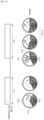
- In one embodiment of the present invention, in the compressing operation, when the main compression operation is finished, the rotation plate included in the compression unit may be disposed at a second position which is a direction opposite to a first position at which the rotation plate starts to rotate in the initial compression operation.
- To achieve the above objects, according to another embodiment of the present invention, there is provided a method of collecting dust performed by a cleaner station including a housing coupled to a dust bin of a cleaner, a dust collection motor disposed inside the housing to generate a suction force to suction dust inside the dust bin, and a collection unit in which a space for collecting the dust suctioned from the interior of the dust bin is provided, the method including a cover opening operation of opening a discharging cover of the dust bin so that an interior of the housing communicates with the interior of the dust bin after the dust bin is coupled to the housing, a door opening operation of opening a door disposed on a coupling unit to which the dust bin is coupled, a dust collection operation of collecting dust inside the collection unit by driving the dust collection motor, and a compressing operation of compressing the collected dust by a rotation operation of a compression unit disposed inside the collection unit, wherein the compression unit includes a fixed plate fixedly disposed at one side of the interior of the collection unit, and a rotation plate formed to compress dust disposed between the rotation plate and the fixed plate while rotating inside the collection unit, and in the main compression operation, a start position, which is a position at which the rotation plate starts to rotate, and a stop position, which is a position at which the rotation plate ends to rotate, are positioned at opposite sides of the fixed plate.
- In another embodiment of the present invention, the compressing operation may include measuring a rotation angle of the rotation plate and calculating an amount of collected dust stored in the collection unit.
- In another embodiment of the present invention, the compressing operation may further include an initial compression operation in which the rotation of the rotation plate is performed before the dust collecting operation when the amount of collected dust stored inside the collection unit is a predetermined amount or more.
- In another embodiment of the present invention, the initial compression operation may include compressing the collected dust by a rotation plate rotating once in a forward or reverse direction.
- According to the present invention, since the compression unit compresses dust while moving in the internal space of the collection unit, it is possible to increase storage efficiency of the dust collected in the collection unit.
- In addition, according to the present invention, since an amount of dust collected in the collection unit is displayed on the display unit, the user can easily check the amount of dust collected in the collection unit without taking the collection unit out and checking the amount of dust.
- In addition, according to the present invention, since the amount of collected dust compressed and stored inside the collection unit is displayed on the display unit as the warning alarm through the plurality of stages, the user can select the appropriate time desired by the user and remove the dust before the collection unit is filled with dust.
- In addition, according to the present invention, since the amount of dust collected in the collection unit is calculated through the rotation angle of the compressing unit and the rotation angle is calculated based on the number of times the pattern formed in the driving gear is changed, it is possible to accurately calculate the amount of dust even when the rotation speed of the compression unit is changed due to the stuck foreign substances or the like.
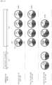
- In addition, according to the present invention, since the stop position of the rotation plate after the process of compressing dust is finished is always positioned at the side opposite to the stop position in the previous compressing process, the dust can be evenly distributed and accumulated at the left and right sides of the rotation plate. Accordingly, it is possible to prevent the problem that the compressed dust blocks the inlet.
- In addition, according to the present invention, since the initial compression operation of compressing the dust scattered inside the collection unit in advance is performed prior to the driving of the dust collection motor before the main compression process, it is possible to widely secure the space in which the dust is accommodated before the dust is collected.
- Effects of the present invention are not limited to the above-described effects, and other effects that are not described will be able to be clearly understood by those skilled in the art from the above detailed description.
-
-
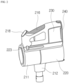
FIG. 1 is a view for describing a cleaner in a cleaner system according to an embodiment of the present invention. -
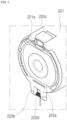
FIG. 2 is a view illustrating the cleaner ofFIG. 1 viewed at another angle. -
FIG. 3 is a view for describing a bottom surface of a dust bin of the cleaner in the cleaner system according to the embodiment of the present invention. -
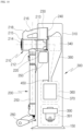
FIG. 4 is a view for describing the cleaner system according to the embodiment of the present invention. -
FIG. 5 is a view for describing a coupling unit in a cleaner station according to an embodiment of the present invention. -
FIG. 6 is a view for describing a fixing unit in the cleaner station according to the embodiment of the present invention. -
FIG. 7 is a view illustrating a state in which a door closes a dust through hole. -
FIG. 8 is a view illustrating a state in which the door opens the dust through hole. -
FIG. 9 is a view for describing a relationship between the cleaner and a cover open unit in the cleaner station according to the embodiment of the present invention. -
FIG. 10 is a view for describing the arrangement between components of the cleaner station according to the embodiment of the present invention. -
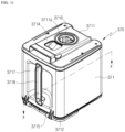
FIG. 11 is a perspective view for describing a collection unit in the cleaner station according to the embodiment of the present invention. -
FIG. 12 is an exploded view separately illustrating components included in the collection unit and components coupled to the collection unit. -
FIG. 13 is a cross-sectional view along line X-X' inFIG. 11 . -
FIG. 14 is a view illustrating a direction in which air is suctioned in a state in which the collection unit is inserted into a housing. -
FIG. 15 is an enlarged view illustrating a driving gear and a transmission gear. -
FIG. 16 is a view for describing a pattern formed on the driving gear. -
FIG. 17 is a view illustrating a relationship between the driving gear and a compression state detection unit. -
FIG. 18 is a view for describing the detection principle of the compression state detection unit. -
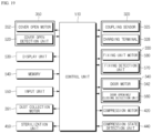
FIG. 19 is a block diagram of the cleaner station according to the embodiment of the present invention. -
FIG. 20 illustrates one embodiment in which an alarm on a dust compression state is guided through a display unit. -
FIG. 21 is a flowchart illustrating a flow of a method of collecting dust of the cleaner station according to the embodiment of the present invention. -
FIG. 22 is a view illustrating an operation sequence of each motor included in the cleaner station in the embodiment ofFIG. 21 . -
FIG. 23 is a view for describing the operation of the compression unit performed in a dust compressing operation ofFIG. 21 in more detail. -
FIG. 24 is a flowchart illustrating a second embodiment of the method of collecting dust of the cleaner station. -
FIG. 25 is a view for describing the operation of the compression unit performed in a dust compressing operation ofFIG. 24 in more detail. - Hereinafter, exemplary embodiments of the present invention will be described in detail with reference to the accompanying drawings.
- Since the present invention may have various changes and various embodiments, specific embodiments are shown in the accompanying drawings and specifically described in the detail descriptions. This is not intended to limit the present invention to specific embodiments and should be construed to include all modifications, equivalents, and substitutes included in the spirit and technical scope of the present invention.
-
FIG. 1 is a view for describing a cleaner in a cleaner system according to an embodiment of the present invention,FIG. 2 is a view illustrating the cleaner ofFIG. 1 viewed at another angle,FIG. 3 is a view for describing a bottom surface of a dust bin of the cleaner in the cleaner system according to the embodiment of the present invention, andFIG. 4 is a view for describing the cleaner system according to the embodiment of the present invention. - Referring to
FIGS. 1 to 4 , acleaner system 3 according to an embodiment of the present invention may include a cleaner 200 and acleaner station 300. - The
cleaner system 3 may include thecleaner station 300. The cleaner 200 may be coupled to thecleaner station 300. The cleaner 200 may be coupled to a side surface of thecleaner station 300. Thecleaner station 300 may remove dust of adust bin 220 of the cleaner 200. - First, a structure of the cleaner 200 will be described with reference to
FIGS. 1 to 3 . - The cleaner 200 may be a cleaner which is manually manipulated by a user. For example, the cleaner 200 may be a hand cleaner or a stick cleaner.
- The cleaner 200 may be caught on the
cleaner station 300. The cleaner 200 may be supported by thecleaner station 300. The cleaner 200 may be coupled to thecleaner station 300. - Meanwhile, in the embodiment of the present invention, a direction of the cleaner 200 may be defined based on when bottom surfaces (lower surfaces) of the
dust bin 220 and abattery housing 230 are disposed on the ground. - In this case, the front may be a direction in which a
suction unit 212 is disposed with respect to asuction motor 214, and the rear may be a direction in which ahandle 216 is disposed with respect to thesuction motor 214. In addition, a direction disposed at the right may be referred to as a right side, and a direction disposed at the left may be referred to as a left side based on when viewing thesuction unit 212 from thesuction motor 214. In addition, in the embodiment of the present invention, an upper side and a lower side may be defined in a direction perpendicular to the ground based on when the bottom surfaces (lower surfaces) of thedust bin 220 and thebattery housing 230 are disposed on the ground. - The cleaner 200 may include a
main body 210. Themain body 210 may include amain body housing 211, thesuction unit 212, adust separator 213, thesuction motor 214, anair discharging cover 215, thehandle 216, and amanipulation unit 218. - The
main body housing 211 may form an exterior of the cleaner 200. Themain body housing 211 may provide a space in which thesuction motor 214 and a filter (not illustrated) may be accommodated. Themain body housing 211 may be formed in a shape similar to a cylinder. - The
suction unit 212 may protrude outward from themain body housing 211. As an example, thesuction unit 212 may be formed in a cylindrical shape with an open interior. Thesuction unit 212 may be coupled to anextension pipe 250. Thesuction unit 212 may provide a flow path (hereinafter referred to as "suction flow path") along which air containing dust may flow. - The
dust separator 213 may communicate with thesuction unit 212. Thedust separator 213 may separate dust suctioned therein through thesuction unit 212. An internal space of thedust separator 213 may communicate with an internal space of thedust bin 220. - For example, the
dust separator 213 may have at least one cyclone unit capable of separating dust by a cyclonic flow. In addition, the internal space of thedust separator 213 may communicate with the suction flow path. Accordingly, the air and dust suctioned through thesuction unit 212 spirally flow along an inner circumferential surface of thedust separator 213. Accordingly, a cyclonic flow may occur in the internal space of thedust separator 213. - The
dust separator 213 is a component which communicates with thesuction unit 212 and adopts the principle of a dust collector using a centrifugal force to separate dust suctioned into themain body 210 through thesuction unit 212. - The
dust separator 213 may further include a secondary cyclone which reseparates dust from the air discharged from the cyclone. In this case, the secondary cyclone may be positioned inside the cyclone to minimize a size of the dust separator. The secondary cyclone may include a plurality of cyclone bodies disposed in parallel. The air discharged from the cyclone may be partitioned into the plurality of cyclone bodies and may pass through the partitioned cyclone bodies. - In this case, an axis of the cyclonic flow of the secondary cyclone may also extend vertically, and an axis of the cyclonic flow of the cyclone and the axis of the cyclonic flow of the secondary cyclone may be coaxial vertically and may be collectively referred to as an axis of the cyclonic flow of the
dust separator 213. - The
suction motor 214 may generate a suction force of suctioning air. Thesuction motor 214 may be accommodated in themain body housing 211. Thesuction motor 214 may generate a suction force by rotation. As an example, thesuction motor 214 may be provided in a shape similar to a cylindrical shape. - The
air discharging cover 215 may be disposed at one side of themain body housing 211 in an axial direction. Theair discharging cover 215 may accommodate a filter for filtering air. For example, theair discharging cover 215 may accommodate a HEPA filter. - An air outlet through which the air suctioned by the suction force of the
suction motor 214 is discharged may be formed on theair discharging cover 215. - A flow guide may be disposed on the
air discharging cover 215. The flow guide may guide a flow of the air discharged through the air outlet. - The
handle 216 may be gripped by a user. Thehandle 216 may be disposed behind thesuction motor 214. As an example, thehandle 216 may be formed in a shape similar to a cylindrical shape. Alternatively, thehandle 216 may be formed in a curved cylindrical shape. Thehandle 216 may be disposed at a predetermined angle with themain body housing 211, thesuction motor 214, or thedust separator 213. - The
handle 216 may include agrip portion 216a formed in a pillar shape to be gripped by the user, afirst extension 216b connected to one end portion of thegrip portion 216a in a longitudinal direction (axial direction) and formed to extend toward thesuction motor 214, and asecond extension 216c connected to the other end portion of thegrip portion 216a in the longitudinal direction (axial direction) and formed to extend toward thedust bin 220. - An upper surface of the
handle 216 may form a partial exterior of an upper surface of the cleaner 200. Accordingly, when the user grips thehandle 216, one component of the cleaner 200 can be prevented from being in contact with an arm of the user. - The
first extension 216b may extend from thegrip portion 216a to themain body housing 211 or thesuction motor 214. At least a part of thefirst extension 216b may extend in a horizontal direction. - The
second extension 216c may extend from the grip portion to thedust bin 220. At least a part of thesecond extension 216c may extend in the horizontal direction. - The
manipulation unit 218 may be disposed on thehandle 216. Themanipulation unit 218 may be disposed on an inclined surface formed in an upper area of thehandle 216. The user may input an operation or stop command of the cleaner 200 through themanipulation unit 218. - The
manipulation unit 218 may visually display information (e.g., suction strength, a remaining charging level of a battery, and the like) about the operation of the cleaner 200. That is, themanipulation unit 218 may serve as a display device. - The cleaner 200 may include the
dust bin 220. Thedust bin 220 may communicate with thedust separator 213. Thedust bin 220 may store the dust separated by thedust separator 213. - The
dust bin 220 may include a dust binmain body 221, a discharging cover 222, a dustbin compression lever 223, and a compression member (not illustrated). - The dust bin
main body 221 may provide a space in which the dust separated by thedust separator 213 may be stored. As an example, the dust binmain body 221 may be formed in a shape similar to a cylindrical shape. - A part of a lower surface (bottom surface) of the dust bin
main body 221 may be opened. In addition, alower surface extension 221a may be formed on the lower surface (bottom surface) of the dust binmain body 221. Thelower surface extension 221a may be formed to block a part of the lower surface of the dust binmain body 221. - The
dust bin 220 may include the discharging cover 222. The discharging cover 222 may be disposed on the lower surface of thedust bin 220. - The discharging cover 222 may be provided to open and close one end portion of the dust bin
main body 221 in the longitudinal direction. Specifically, the discharging cover 222 may selectively open and close a downward open lower portion of thedust bin 220. - The discharging cover 222 may include a cover
main body 222a and ahinge unit 222b. The covermain body 222a may be formed to block a part of the lower surface of the dust binmain body 221. The covermain body 222a may rotate downward with respect to thehinge unit 222b. Thehinge unit 222b may be disposed adjacent to thebattery housing 230. Thehinge unit 222b may be provided with atorsion spring 222d. Accordingly, when the discharging cover 222 is separated from the dust binmain body 221, the covermain body 222a may be supported while rotated about thehinge unit 222b at a predetermined angle or more in the dust binmain body 221 by an elastic force of thetorsion spring 222d. - The discharging cover 222 may be coupled to the
dust bin 220 through hook coupling. Meanwhile, the discharging cover 222 may be separated from thedust bin 220 through acoupling lever 222c. Thecoupling lever 222c may be disposed at the front of the dust bin. Specifically, thecoupling lever 222c may be disposed on a front outer surface of thedust bin 220. When an external force is applied, thecoupling lever 222c may elastically deform a hook formed to extend from the covermain body 222a to release the hook coupling between the covermain body 222a and the dust binmain body 221. - When the discharging cover 222 is closed, the lower surface of the
dust bin 220 may be blocked (sealed) by the discharging cover 222 and thelower surface extension 221a. - The
dust bin 220 may include the dust bin compression lever 223 (seeFIG. 2 ). The dustbin compression lever 223 may be disposed outside thedust bin 220 or thedust separator 213. The dustbin compression lever 223 may be disposed to move upward and downward outside thedust bin 220 or thedust separator 213. The dustbin compression lever 223 may be connected to a compression member (not illustrated). When the dustbin compression lever 223 is moved downward by an external force, the compression member (not illustrated) may also move downward. Accordingly, user convenience can be provided. The compression member (not illustrated) and the dustbin compression lever 223 may be returned to original positions by an elastic member (not illustrated). Specifically, when the external force applied to the dustbin compression lever 223 is removed, the elastic member may move the dustbin compression lever 223 and the compression member (not illustrated) upward. - The compression member (not illustrated) may be disposed inside the dust bin
main body 221. The compression member may move in an internal space of the dust binmain body 221. Specifically, the compression member may move upward and downward in the dust binmain body 221. Accordingly, the compression member may compress the dust in the dust binmain body 221 downward. In addition, when the discharging cover 222 is separated from the dust binmain body 221 and the lower portion of thedust bin 220 is opened, the compression member may move from the upper portion to the lower portion of thedust bin 220 to remove foreign substances such as the remaining dust in thedust bin 220. Accordingly, it is possible to increase the suction force of the cleaner by preventing the remaining dust from remaining in thedust bin 220. In addition, bad odors generated by the residue can be removed by preventing the remaining dust from remaining in thedust bin 220. - The cleaner 200 may include the
battery housing 230. Abattery 240 may be accommodated in thebattery housing 230. Thebattery housing 230 may be disposed under thehandle 216. As an example, thebattery housing 230 may have a hexahedral shape with an open lower portion. A rear surface of thebattery housing 230 may be connected to thehandle 216. - The
battery housing 230 may include an accommodation portion which is opened downward. Thebattery 240 may be detachably attached through the accommodation portion of thebattery housing 230. - The cleaner 200 may include the
battery 240. - For example, the
battery 240 may be detachably coupled to the cleaner 200. Thebattery 240 may be detachably coupled to thebattery housing 230. As an example, thebattery 240 may be inserted into thebattery housing 230 from the bottom of thebattery housing 230. With this configuration, it is possible to improve the portability of the cleaner 200. - Alternatively, the
battery 240 may be provided integrally inside thebattery housing 230. In this case, a lower surface of thebattery 240 is not exposed to the outside. - The
battery 240 may supply power to thesuction motor 214 of the cleaner 200. Thebattery 240 may be disposed under thehandle 216. Thebattery 240 may be disposed behind thedust bin 220. - According to an embodiment, when the
battery 240 is coupled to thebattery housing 230, the lower surface of thebattery 240 may be exposed to the outside. Since thebattery 240 may be disposed on the floor when the cleaner 200 is disposed on the floor, thebattery 240 may be immediately separated from thebattery housing 230. In addition, since the lower surface of thebattery 240 is exposed to the outside and in direct contact with external air of thebattery 240, it is possible to improve cooling performance of thebattery 240. - Meanwhile, when the
battery 240 is integrally fixed to thebattery housing 230, a structure for detachably attaching thebattery 240 to thebattery housing 230 can be smaller, thereby reducing the overall size of the cleaner 200 and achieving lightweight. - The cleaner 200 may include the
extension pipe 250. Theextension pipe 250 may communicate with acleaning module 260. Theextension pipe 250 may communicate with themain body 210. Theextension pipe 250 may communicate with thesuction unit 212 of themain body 210. Theextension pipe 250 may be formed in a long cylindrical shape. - The
main body 210 may be connected to theextension pipe 250. Themain body 210 may be connected to thecleaning module 260 through theextension pipe 250. Themain body 210 may generate the suction force through thesuction motor 214 and provide the suction force to thecleaning module 260 through theextension pipe 250. External dust may flow into themain body 210 through thecleaning module 260 and theextension pipe 250. - The cleaner 200 may include the
cleaning module 260. Thecleaning module 260 may communicate with theextension pipe 250. Accordingly, external air may pass through thecleaning module 260 and theextension pipe 250 and may be introduced into themain body 210 of the cleaner 200 by the suction force generated from themain body 210 of the cleaner 200. - The dust in the
dust bin 220 of the cleaner 200 may be collected in thecollection unit 370 of thecleaner station 300 by gravity. At the same time, the dust in thedust bin 220 may be collected in thecollection unit 370 of thecleaner station 300 by the suction force of thedust collection motor 391 disposed inside thecleaner station 300. Accordingly, since the dust in the dust bin may be removed without separate manipulation of the user, user convenience can be provided. In addition, it is possible to eliminate the inconvenience of the user having to empty the dust bin every time. In addition, it is possible to prevent dust from scattering when the user empties the dust bin. - The cleaner 200 may be coupled to a side surface of a
housing 310. Specifically, themain body 210 of the cleaner 200 may be caught on acoupling unit 320. More specifically, thedust bin 220 and thebattery housing 230 of the cleaner 200 may be coupled to acoupling surface 321 of thecoupling unit 320. An outer circumferential surface of the dust binmain body 221 may be coupled to a dustbin guide surface 322. Thesuction unit 212 may be coupled to the suctionunit guide surface 326 of thecoupling unit 320. With this configuration, a center axis of thedust bin 220 may be disposed in a direction parallel to the ground, and theextension pipe 250 may be disposed in a direction perpendicular to the ground. - Hereinafter, a configuration of the
cleaner station 300 according to the embodiment of the present invention will be described. - Referring to
FIG. 4 , the cleaner 200 may be coupled to thecleaner station 300. Specifically, the main body of the cleaner 200 may be coupled to the side surface of thecleaner station 300. More specifically, thedust bin 220 of the cleaner 200 may be coupled to the side surface of thecleaner station 300 and coupled through one side at which the discharging cover 222 is disposed. Accordingly, when the discharging cover 222 is opened, the dust in thedust bin 220 may be collected inside thecleaner station 300 and removed. - The
cleaner station 300 may include thehousing 310. Thehousing 310 may form the exterior of thecleaner station 300. Specifically, thehousing 310 may be formed in a pillar shape including at least one outer wall surface. As an example, thehousing 310 may be formed in a shape similar to a quadrangular pillar. - A space, which may accommodate the
collection unit 370 and adust suction module 390, may be formed inside thehousing 310. - The
housing 310 may include abottom surface 311, anouter wall surface 312, and anupper surface 313. - The
bottom surface 311 may support a lower side of thedust suction module 390 in a direction of gravity. That is, thebottom surface 311 may support the lower side of thedust collection motor 391 of thedust suction module 390. - In this case, the
bottom surface 311 may be disposed toward the ground. Thebottom surface 311 may be not only disposed parallel to the ground, but also disposed to be inclined at a predetermined angle with the ground. With this configuration, there is an advantage that thedust collection motor 391 can be stably supported and the overall weight can be balanced even when the cleaner 200 is coupled. - Meanwhile, according to an embodiment, the
bottom surface 311 may further include aground support 311a which increases an area in contact with the ground to prevent thecleaner station 300 from falling down and maintain balance. As an example, theground support 311a may be in the form of a plate extending from thebottom surface 311, and one or more frames may be formed to protrude and extend from thebottom surface 311 toward the ground. - The
outer wall surface 312 may be a surface formed in the direction of gravity and may be a surface connected to thebottom surface 311. For example, theouter wall surface 312 may be a surface connected perpendicular to thebottom surface 311. In another embodiment, theouter wall surface 312 may be disposed to be inclined at a predetermined angle with thebottom surface 311. - The
outer wall surface 312 may include at least one surface. As an example, theouter wall surface 312 may include a firstouter wall surface 312a, a second outer wall surface 312b, a thirdouter wall surface 312c, and a fourth outer wall surface 312d. - In this case, in the present embodiment, the first
outer wall surface 312a may be disposed on a front surface of thecleaner station 300. Here, the front surface may be a surface on which the cleaner 200 is exposed in a state in which the cleaner 200 is coupled to thecleaner station 300. Accordingly, the firstouter wall surface 312a may form an exterior of the front surface of thecleaner station 300. - Meanwhile, for understanding of the present embodiment, directions are defined as follows. In the present embodiment, directions may be defined in a state in which the cleaner 200 is coupled to the
cleaner station 300. - When the cleaner 200 is coupled to the
cleaner station 300, a direction in which the cleaner 200 is exposed to the outside of thecleaner station 300 may be referred to as the front. - From another perspective, when the cleaner 200 is coupled to the
cleaner station 300, a direction in which thesuction motor 214 of the cleaner 200 is disposed may be referred to as the front. In addition, a direction opposite to the direction in which thesuction motor 214 is disposed in thecleaner station 300 may be referred to as the rear. - In addition, a surface in a direction facing the front surface based on the internal space of the
housing 310 may be referred to as the rear surface of thecleaner station 300. Accordingly, the rear surface may refer to a direction in which the second outer wall surface 312b is formed. - In addition, when viewing the front surface based on the internal space of the
housing 310, a surface at the left may be referred to as a left surface, and a surface at the right may be referred to as a right surface. Accordingly, the left surface may refer to a direction in which the thirdouter wall surface 312c is formed, and the right surface may refer to the direction in which the fourth outer wall surface 312d is formed. - The first
outer wall surface 312a may be formed not only in a flat shape, but also entirely in a curved shape, and a part thereof may be formed to include a curved surface. - The
coupling unit 320 may be disposed on the firstouter wall surface 312a. With this configuration, the cleaner 200 may be coupled to thecleaner station 300 and supported by thecleaner station 300. A specific configuration of thecoupling unit 320 will be described below. - Meanwhile, a structure in which various types of cleaning
modules 260 used in the cleaner 200 are caught may be added to the firstouter wall surface 312a. - In the present embodiment, the second outer wall surface 312b may be a surface facing the first
outer wall surface 312a. That is, the second outer wall surface 312b may be disposed on the rear surface of thecleaner station 300. The second outer wall surface 312b may form an exterior of the rear surface of thecleaner station 300. - In the present embodiment, the third
outer wall surface 312c and the fourth outer wall surface 312d may be surfaces which connect the firstouter wall surface 312a to the second outer wall surface 312b. In this case, the thirdouter wall surface 312c may be disposed on the left surface of thecleaner station 300, and the fourth outer wall surface 312d may be disposed on the right surface of thecleaner station 300. Alternatively, the thirdouter wall surface 312c may be disposed on the right surface of thecleaner station 300, and the fourth outer wall surface 312d may be disposed on the left surface of thecleaner station 300. - The third
outer wall surface 312c or the fourth outer wall surface 312d may be formed not only in a flat shape, but also entirely in a curved shape, and a part thereof may be formed to include a curved surface. - Meanwhile, a structure in which various types of cleaning
modules 260 used in the cleaner 200 are caught may be added to the thirdouter wall surface 312c or the fourth outer wall surface 312d. - The
upper surface 313 may form an exterior of the upper side of the cleaner station. That is, theupper surface 313 may be a surface which is disposed at the uppermost side of the cleaner station in the direction of gravity and exposed to the outside in the cleaner station. - For reference, in the present embodiment, an upper side and a lower side may be an upper side and a lower side, respectively, in the direction of gravity (in a direction perpendicular to the ground) in a state in which the
cleaner station 300 is installed on the ground. - In this case, the
upper surface 313 may be disposed not only parallel to the ground, but also to be inclined at a predetermined angle with the ground. - A
display unit 530 may be disposed on theupper surface 313. As an example, thedisplay unit 530 may display the state of thecleaner station 300 and the state of the cleaner 200 and also display information such as a cleaning progress, a map of a cleaning zone, and the like. - Meanwhile, according to an embodiment, the
upper surface 313 may be provided separately from theouter wall surface 312. In this case, when theupper surface 313 is separated, a battery separated from the cleaner 200 may be accommodated in the internal space surrounded by theouter wall surface 312 and provided with a terminal (not illustrated) for charging the separated battery. -
FIG. 5 is a view for describing a coupling unit in a cleaner station according to an embodiment of the present invention. - Referring to
FIG. 5 , thecleaner station 300 may include thecoupling unit 320 to be coupled to the cleaner 200. Specifically, thecoupling unit 320 may be disposed on the firstouter wall surface 312a, and thedust bin 220 of the cleaner 200 may be coupled. Thecoupling unit 320 may also be coupled to themain body 210 and thebattery housing 230 of the cleaner 200 along with thedust bin 220. - The
coupling unit 320 may include thecoupling surface 321. Thecoupling surface 321 may be disposed on a side surface of thehousing 310. As an example, thecoupling surface 321 may be a surface formed in a groove shape which is concave from the firstouter wall surface 312a to the interior of thecleaner station 300. That is, thecoupling surface 321 may be a surface formed by forming a step with the firstouter wall surface 312a. - The cleaner 200 may be coupled to the
coupling surface 321. As an example, thecoupling surface 321 may be in contact with the lower surfaces of thedust bin 220 and thebattery housing 230 of the cleaner 200. Here, the lower surface may be a surface toward the ground when the user uses the cleaner 200 or arranges the cleaner 200 on the ground. - As an example, an angle formed by the
coupling surface 321 and the ground may be a right angle. Accordingly, when the cleaner 200 is coupled to thecoupling surface 321, it is possible to minimize a space of thecleaner station 300. - As another example, the
coupling surface 321 may be disposed to be inclined at a predetermined angle with the ground. Accordingly, when the cleaner 200 is coupled to thecoupling surface 321, thecleaner station 300 can be stably supported. - A dust through
hole 321a may be formed in thecoupling surface 321 so that external air of thehousing 310 flows into thehousing 310. The dust throughhole 321a may be formed in a hole shape corresponding to the shape of thedust bin 220 so that the dust in thedust bin 220 flows into thecollection unit 370. The dust throughhole 321a may be formed to correspond to the shape of the discharging cover 222 of thedust bin 220. The dust throughhole 321a may be formed to communicate with aflow path unit 380 to be described below (seeFIG. 8 ). - The
coupling unit 320 may include the dustbin guide surface 322. The dustbin guide surface 322 may be disposed on the firstouter wall surface 312a. The dustbin guide surface 322 may be connected to the firstouter wall surface 312a. In addition, the dustbin guide surface 322 may be connected to thecoupling surface 321. - The dust
bin guide surface 322 may be formed in a shape corresponding to the outer surface of thedust bin 220. The front outer surface of thedust bin 220 may be coupled to the dustbin guide surface 322. Accordingly, the convenience of coupling the cleaner 200 to thecoupling surface 321 can be provided. - Meanwhile, a
protrusion movement hole 322a may be formed in the dustbin guide surface 322, and apush protrusion 351 to be described below may move linearly along theprotrusion movement hole 322a (seeFIG. 11 ). In addition, agear box 355 for accommodating a gear and the like of a coveropen unit 350 to be described below may be provided under the dustbin guide surface 322 in the direction of gravity. In this case, aguide space 322b in which thepush protrusion 351 may move may be formed between a lower surface of the dustbin guide surface 322 and an upper surface of thegear box 355. In addition, theguide space 322b may communicate with a first flow path 381 through abypass hole 322c. That is, theprotrusion movement hole 322a, theguide space 322b, thebypass hole 322c, and the first flow path 381 may form one flow path. With this configuration, when thedust collection motor 391 is operated in a state in which thedust bin 220 is coupled to thecoupling unit 320, there is an advantage that dust and the like remaining in thedust bin 220 and the dustbin guide surface 322 may be suctioned through the flow path. - The
coupling unit 320 may include a guide protrusion 323. The guide protrusion 323 may be disposed on thecoupling surface 321. The guide protrusion 323 may protrude upward from thecoupling surface 321. Two guide protrusions 323 may be disposed to be spaced apart from each other. A distance between the two guide protrusions 323 spaced apart from each other may correspond to a width of thebattery housing 230 of the cleaner 200. Accordingly, the convenience of coupling the cleaner 200 to thecoupling surface 321 can be provided. - The
coupling unit 320 may include a couplingunit side wall 324. The couplingunit side wall 324 may be a wall surface disposed on both side surfaces of thecoupling surface 321 and connected perpendicular to thecoupling surface 321. The couplingunit side wall 324 may be connected to the firstouter wall surface 312a. In addition, the couplingunit side wall 324 may form a surface connected to the dustbin guide surface 322. Accordingly, the cleaner 200 can be stably accommodated. - The
coupling unit 320 may include a coupling sensor. The coupling sensor may detect whether the cleaner 200 is coupled to thecoupling unit 320. - The coupling sensor may include a contact sensor. As an example, the coupling sensor may include a micro switch. In this case, the coupling sensor may be disposed on the guide protrusion 323. Accordingly, when the
battery housing 230 or thebattery 240 of the cleaner 200 is coupled between the pair of guide protrusions 323, thecleanser 200 may be in contact with the coupling sensor 125, and the coupling sensor may detect that the cleaner 200 has been coupled. - Meanwhile, the coupling sensor may include a non-contact sensor. As an example, the coupling sensor may include an infrared (IR) sensor. In this case, the coupling sensor may be disposed on the coupling
unit side wall 324. Accordingly, when thedust bin 220 or themain body 210 of the cleaner 200 reaches thecoupling surface 321 after passing through the couplingunit side wall 324, the coupling sensor may detect the presence of thedust bin 220 or themain body 210. - In a state in which the cleaner 200 is coupled to the
cleaner station 300, the coupling sensor may face thedust bin 220 or thebattery housing 230 of the cleaner 200. - The coupling sensor may be a unit for determining whether power is applied to the
battery 240 of the cleaner 200 and whether the cleaner 200 has been coupled. - The
coupling unit 320 may include a suctionunit guide surface 326. The suctionunit guide surface 326 may be disposed on the firstouter wall surface 312a. The suctionunit guide surface 326 may be connected to the dustbin guide surface 322. Thesuction unit 212 may be coupled to the suctionunit guide surface 326. A shape of the suctionunit guide surface 326 may be formed in a shape corresponding to the shape of thesuction unit 212. - The
coupling unit 320 may further include a fixingmember entrance hole 327. The fixingmember entrance hole 327 may be formed in the form of a long hole along the couplingunit side wall 324 so that the fixingmember 331 enters and exits. - With this configuration, when the user couples the cleaner 200 to the
coupling unit 320 of thecleaner station 300, themain body 210 of the cleaner 200 can be stably disposed on thecoupling unit 320 by the dustbin guide surface 322, the guide protrusion 323, and the suctionunit guide surface 326. Accordingly, the convenience of coupling thedust bin 220 and thebattery housing 230 of the cleaner 200 to thecoupling surface 321 can be provided. - Meanwhile, the
cleaner station 300 may further include a chargingterminal 328. The chargingterminal 328 may be disposed on thecoupling unit 320. The chargingterminal 328 may be electrically connected to the cleaner 200 coupled to thecoupling unit 320. The chargingterminal 328 may supply power to the battery of the cleaner 200 coupled to thecoupling unit 320. - In addition, the
cleaner station 300 may further include a side door. The side door may be disposed in thehousing 310. The side door may selectively expose thecollection unit 370 to the outside. Accordingly, the user can easily remove thecollection unit 370 from thecleaner station 300. -
FIG. 6 is a view for describing a fixing unit in the cleaner station according to the embodiment of the present invention. - Referring to
FIG. 6 , thecleaner station 300 of the present invention may include a fixingunit 330. The fixingunit 330 may be disposed on the couplingunit side wall 324. In addition, the fixingunit 330 may be disposed on the rear surface of thecoupling surface 321. The fixingunit 330 may fix the cleaner 200 coupled to thecoupling surface 321. Specifically, the fixingunit 330 may fix thedust bin 220 and thebattery housing 230 of the cleaner 200 coupled to thecoupling surface 321. - The fixing
unit 330 may include a fixingmember 331 for fixing thedust bin 220 and thebattery housing 230 of the cleaner 200, and a fixingunit motor 580 for driving the fixingmember 331. In addition, the fixingunit 330 may further include a fixingunit link 335 for transmitting the power of the fixingunit motor 580 to the fixingmember 331. - The fixing
member 331 may be disposed on the couplingunit side wall 324 and provided to reciprocate on the couplingunit side wall 324 to fix thedust bin 220. Specifically, the fixingmember 331 may be accommodated inside the fixingmember entrance hole 327. - The fixing
member 331 may be disposed at each of both sides of thecoupling unit 320. As an example, a pair of two fixingmembers 331 may be disposed symmetrically with respect to thecoupling surface 321. - The fixing
unit motor 580 may provide power for moving the fixingmember 331. - The fixing
unit link 335 may convert a rotational force of the fixingunit motor 580 into the reciprocating movement of the fixingunit member 331. - When the cleaner 200 is coupled, a fixing
sealer 336 may be disposed on the dustbin guide surface 322 to airtighten thedust bin 220. With this configuration, when thedust bin 220 of the cleaner 200 is coupled, the fixingsealer 336 may be pressed by the weight of the cleaner 200, and thedust bin 220 and the dustbin guide surface 322 may be sealed. - The fixing
sealer 336 may be disposed on a virtual extension line of the fixingmember 331. With this configuration, when the fixingunit motor 580 is operated so that the fixingmember 331 presses thedust bin 220, a perimeter of thedust bin 220 at the same height may be sealed. - According to an embodiment, the fixing
sealer 336 may be disposed on the dustbin guide surface 322 in a bent line shape corresponding to the arrangement of the coveropen unit 350 to be described below. - Accordingly, when the
main body 210 of the cleaner 200 is disposed on thecoupling unit 320, the fixingunit 330 may fix themain body 210 of the cleaner 200. Specifically, when thecoupling sensor 325 detects that themain body 210 of the cleaner 200 is coupled to thecoupling unit 320 of thecleaner station 300, the fixingunit motor 580 may move the fixingmember 331 to fix themain body 210 of the cleaner 200. - Accordingly, it is possible to increase the suction force of the cleaner by preventing the remaining dust from remaining in the dust bin. In addition, bad odors generated by the residue can be removed by preventing the remaining dust from remaining in the dust bin.
-
FIGS. 7 and8 are views for describing a relationship between the cleaner and a door unit in the cleaner station according to the embodiment of the present invention,FIG. 7 is a view illustrating a state in which a door closes a dust through hole, andFIG. 8 is a view illustrating a state in which the door opens the dust through hole. - Referring to
FIGS. 7 and8 , thecleaner station 300 of the present invention may include adoor unit 340. Thedoor unit 340 may be formed to open and close the dust throughhole 321a. - The
door unit 340 may include adoor 341, adoor motor 342, and adoor arm 343. - The
door 341 may be hinge-coupled to thecoupling surface 321 to open and close the dust throughhole 321a. Thedoor 341 may include a doormain body 341a. - The door
main body 341a may be formed in a shape which may block the dust throughhole 321a. As an example, the doormain body 341a may be formed in a shape similar to a disk shape. - Based on a state in which the door
main body 341a blocks the dust throughhole 321a, a hinge unit may be disposed above thedoor body 341a, and anarm coupling portion 341b may be disposed under the doormain body 341a. - The door
main body 341a may be formed in a shape which may airtighten the dust throughhole 321a. As an example, an outer surface of the doormain body 341a, which is exposed outward from thecleaner station 300, is formed to have a diameter corresponding to a diameter of the dust throughhole 321a, and an inner surface of the doormain body 341a, which is disposed inside thecleaner station 300, is formed to have a diameter greater than the diameter of the dust throughhole 321a. In addition, a step may occur between the outer surface and inner surface of the doormain body 341a. Meanwhile, at least one reinforcing rib for connecting the hinge unit to thearm coupling portion 341b and reinforcing support strength of the doormain body 341a may be formed to protrude from the inner surface of the doormain body 341a. - The hinge unit may be a unit for hinge-coupling the
door 341 to thecoupling surface 321. The hinge unit may be disposed at an upper end portion of the doormain body 341a and coupled to thecoupling surface 321. - The
arm coupling portion 341b may be a portion to which thedoor arm 343 is rotatably coupled. Thearm coupling portion 341b may be disposed under the doormain body 341a, rotatably coupled to the doormain body 341a, and rotatably coupled to thedoor arm 343. - With this configuration, in a state in which the
door 341 closes the dust throughhole 321a, when thedoor arm 343 pulls the doormain body 341a, the doormain body 341a may move while rotating about the hinge unit inward from thecleaner station 300 to open the dust throughhole 321a. Meanwhile, in a state in which the dust throughhole 321a is opened, when thedoor arm 343 pushes the doormain body 341a, the doormain body 341a may move while rotating about thehinge unit 222b outward from thecleaner station 300 to block the dust throughhole 321a. - Meanwhile, in a state in which the cleaner 200 is coupled to the
cleaner station 300 and the discharging cover 222 is separated from the dust binmain body 221, thedoor 341 may be in contact with the discharging cover 222. In addition, as thedoor 341 rotates, the discharging cover 222 may be rotated in conjunction with thedoor 341. - The
door motor 342 may provide power for rotating thedoor 341. Specifically, thedoor motor 342 may rotate thedoor arm 343 in a forward or reverse direction. Here, the forward direction may be a direction in which thedoor arm 343 pulls thedoor 341. Accordingly, when thedoor arm 343 rotates in the forward direction, the dust throughhole 321a may be opened. In addition, the reverse direction may be a direction in which thedoor arm 343 pushes thedoor 341. Accordingly, when thedoor arm 343 rotates in the reverse direction, at least a part of the dust throughhole 321a may be closed. The forward direction may be a direction opposite to the reverse direction. - The
door arm 343 may connect thedoor 341 to thedoor motor 342 and open and close thedoor 341 using the power generated from thedoor motor 342. - As an example, the
door arm 343 may include afirst door arm 343a and asecond door arm 343b. One end portion of thefirst door arm 343a may be coupled to thedoor motor 342. Thefirst door arm 343a may be rotated by the power of thedoor motor 342. The other end portion of thefirst door arm 343a may be rotatably coupled to thesecond door arm 343b. Thefirst door arm 343a may transmit the force transmitted from thedoor motor 342 to thesecond door arm 343b. One end portion of thesecond door arm 343b may be coupled to thefirst door arm 343a. The other end portion of thesecond door arm 343b may be coupled to thedoor 341. Thesecond door arm 343b may open and close the dust throughhole 321a by pushing or pulling thedoor 341. - The
door unit 340 may also be opened when the discharging cover 222 of the cleaner 200 is opened. In addition, when thedoor unit 340 is closed, the discharging cover 222 of the cleaner 200 may also be closed in conjunction with thedoor unit 340. - When the dust in the
dust bin 220 of the cleaner 200 is removed, thedoor motor 342 may rotate thedoor 341 to couple the discharging cover 222 to the dust binmain body 221. Specifically, thedoor motor 342 may rotate thedoor 341 about thehinge unit 222b, and thedoor 341 rotating about thehinge unit 222b may push the discharging cover 222 toward the dust binmain body 221. -
FIG. 9 is a view for describing a relationship between the cleaner and a cover open unit in the cleaner station according to the embodiment of the present invention. - Referring to
FIG. 9 , thecleaner station 300 according to the present invention may include the coveropen unit 350. The coveropen unit 350 may be disposed on thecoupling unit 320 to open the discharging cover 222 of the cleaner 200. - The cover
open unit 350 may include thepush protrusion 351, a coveropen motor 352, a coveropen gear 353, and thegear box 355. - The
push protrusion 351 may move to press thecoupling lever 222c when the cleaner 200 is coupled. - The
push protrusion 351 may be disposed on the dustbin guide surface 322. Specifically, the protrusion movement hole may be formed in the dustbin guide surface 322, and thepush protrusion 351 may be exposed to the outside after passing through the protrusion movement hole. - The
push protrusion 351 may be disposed at a position at which it may push thecoupling lever 222c when the cleaner 200 is coupled. That is, thecoupling lever 222c may be disposed on the protrusion movement hole. In addition, thecoupling lever 222c may be disposed on a movement area of thepush protrusion 351. - The
push protrusion 351 may linearly reciprocate to press thecoupling lever 222c. Specifically, thepush protrusion 351 may be coupled to thegear box 355 to guide linear movement. Thepush protrusion 351 may be coupled to the coveropen gear 353 and moved together by the movement of the coveropen gear 353. - The cover
open motor 352 may provide power for moving thepush protrusion 351. Specifically, the coveropen motor 352 may rotate a motor shaft in the forward or reverse direction. Here, the forward direction may be a direction in which thepush protrusion 351 presses thecoupling lever 222c. In addition, the reverse direction may be a direction in which thepush protrusion 351 pressing thecoupling lever 222c is returned to an original position. The forward direction may be a direction opposite to the reverse direction. - The cover
open gear 353 may be coupled to the coveropen motor 352 to move thepush protrusion 351 using the power of the coveropen motor 352. Specifically, the coveropen gear 353 may be accommodated inside thegear box 355. Adriving gear 353a of the coveropen gear 353 may be coupled to the motor shaft of the coveropen motor 352 to receive power. A drivengear 353b of the coveropen gear 353 may be coupled to thepush protrusion 351 to move thepush protrusion 351. As an example, the drivengear 353b may be provided in the form of a rack gear, engaged with thedriving gear 353a, and may receive power from thedriving gear 353a. - In this case, the discharging cover 222 may be provided with the
torsion spring 222d. The discharging cover 222 may be rotated at a predetermined angle or more by an elastic force of thetorsion spring 222d and supported at the rotated position. Accordingly, the discharging cover 222 may be opened so that the dust throughhole 321a may communicate with the interior of thedust bin 220. - The
gear box 355 may be provided inside thehousing 310, disposed under thecoupling unit 320 in the direction of gravity, and may accommodate the coveropen gear 353 therein. - According to the present invention, the
dust bin 220 may be opened by the coveropen unit 350 without the user separately opening the discharging cover 222 of the cleaner, thereby improving convenience. - In addition, since the discharging cover 222 is opened in a state in which the cleaner 200 is coupled to the
cleaner station 300, it is possible to prevent the scattering of dust. -
FIG. 10 is a view for describing the arrangement between components of thecleaner station 300 according to the embodiment of the present invention. - Referring to
FIG. 10 , the coveropen unit 350 is disposed under thecoupling unit 320, and theflow path 380 is disposed behind thecoupling unit 320 and the coveropen unit 350. - Hereinafter, the flow path extending from the
coupling unit 320 to thecollection unit 370 is referred to as a first flow path 381. Thecollection unit 370 in which dust is collected is connected to and disposed at a lower end portion of the first flow path 381. - The
cleaner station 300 may further include achamber 360 in which a space for accommodating thecollection unit 370 is formed. In this case, thecollection unit 370 may be detachably provided in thechamber 360. Thechamber 360 may be a component which is detachably provided in thehousing 310 or may be an accommodation space of thecollection unit 370, which is formed integrally with thehousing 310. - A
sterilization unit 450 may be disposed on thechamber 360. - The
sterilization unit 450 is a component which is provided to sterilize the dust collected in thecollection unit 370. Thesterilization unit 450 may include a light source for emitting sterilization light and a protective panel disposed under the light source to protect the light source. - In a possible embodiment, the light source and the protective panel may be coupled to the
chamber 360 in the form which is accommodated in a separately provided sterilization unit housing. Alternatively, in a possible embodiment, the light source and the protective panel may be coupled to thechamber 360 in the form which is accommodated in a space formed by bending a part of an upper surface of thechamber 360. - The coupling form of the
sterilization unit 450 and thechamber 360 is not limited to one embodiment as long as the light source of thesterilization unit 450 is disposed to emit sterilization light toward thecollection unit 370. - Here, the light source may include at least one light emitting diode (LED) capable of emitting sterilization light having sterilization power capable of removing bacteria. The sterilization light emitted by the light source may have a wavelength that varies depending on the type of the LED.
- For example, the light source may be an LED that emits ultraviolet light having a UV-C wavelength range. The ultraviolet light is classified as UV-A (315 nm to 400 nm), UV-B (280 nm to 315 nm), and UV-C (200 nm to 280 nm) depending on a wavelength, and among them, ultraviolet light in the UV-C range can damage a DNA double helix of microorganisms and suppress the proliferation of the microorganisms.
- Alternatively, as another example, the light source may be an LED which emits visible light having a wavelength of 405 nm. Blue light having a wavelength of 405 nm has a wavelength in a boundary area between visible light and ultraviolet light and has been proven to have sterilization power.
- The protective panel may be disposed to be spaced a predetermined distance from the light source to prevent damage to the light source. In this case, the protective panel may be formed of a material which maximizes the transmittance of the light source. As an example, the protective panel may be formed of quartz. It is known that quartz does not interfere with the transmission of ultraviolet light in the UV-C range.
- The
cleaner station 300 according to the present invention has an advantage that, by having the sterilizingunit 450, thecleaner station 300 can be hygienically managed even when the dust suctioned from thedust bin 220 of the cleaner 200 is stored in thecollection unit 370 for a long time. - Meanwhile, although not illustrated in
FIG. 10 , the fixingunit 330 and thedoor unit 340 are disposed adjacent to thecoupling unit 320, which has already been described with reference toFIGS. 6 to 8 . - The
cleaner station 300 further includes thecollection unit 370. - The
collection unit 370 may be detachably coupled to thechamber 360. Thecollection unit 370 is provided with an accommodation space to collect the dust suctioned from the interior of thedust bin 220 by thedust collection motor 391. -
FIG. 11 is a perspective view for describing thecollection unit 370 in thecleaner station 300 according to the embodiment of the present invention,FIG. 12 is an exploded view separately illustrating components included in thecollection unit 370 and components coupled to thecollection unit 370, andFIG. 13 is a cross-sectional view along line X-X' inFIG. 11 . - Referring to
FIGS. 11 to 13 , thecollection unit 370 may include acollection unit body 371, a collection unitinner wall 372, and acyclone 373. - The
collection unit body 371 forms an exterior of a space for accommodating dust. In a possible embodiment, thecollection unit body 371 may have a substantially hexahedral shape. In another possible embodiment, thecollection unit body 371 may have a substantially cylindrical shape. - A
transmissive panel 3714 may be disposed on anupper surface 3711 of thecollection unit body 371. - When the
collection unit 370 is coupled to the interior of thechamber 360, thetransmissive panel 3714 is disposed at a position corresponding to a position at which thesterilization unit 450 to be described below is disposed. That is, when thecollection unit 370 is inserted into thechamber 360, thesterilization unit 450 and thetransmissive panel 3714 are disposed to face each other. - In addition, the
transmissive panel 3714 is formed of a material which allows sterilization light emitted from thesterilization unit 450 to transmit toward an interior of thecollection unit body 371. As an example, thetransmissive panel 3714 may be formed of a poly methyl methacrylate (PMMA) material. - A
collection unit hinge 3715 may be disposed at one side of an edge of alower surface 3712 of thecollection unit body 371. When thelower surface 3712 of thecollection unit body 371 rotates about thecollection unit hinge 3715, the interior of thecollection unit body 371 may be opened. Accordingly, the user may discharge the dust collected in thecollection unit body 371 and remove the dust to the outside. - An
inlet 3711a may be formed on theupper surface 3711 of thecollection unit body 371 so that air is introduced from a flow path. As an example, theinlet 3711a may be circular. The first flow path 381 is connected to an upper side of theinlet 3711a. Accordingly, air suctioned by the suction force of thedust collection motor 391 may flow into thecollection unit body 371. Theinlet 3711a may be disposed above a first accommodation space S1 to be described below. - An
inlet cover 3716 may be coupled to theinlet 3711a. Theinlet cover 3716 may be opened by the suction force of thedust collection motor 391. That is, theinlet cover 3716 may be opened toward the internal space (specifically, the first accommodation space S1) of thecollection unit body 371. Theinlet cover 3716 may maintain a state of closing theinlet 3711a when thedust collection motor 391 is not driven and, when thedust collection motor 391 starts to drive, theinlet cover 3716 may open theinlet 3711a. - To this end, the
inlet cover 3716 may be provided with a means for applying a restoring force in a direction of closing theinlet 3711a. The means for applying a restoring force may be, for example, an elastic member, a torsion spring, or the like. With this configuration, in a state in which the suction force is not applied, theinlet cover 3716 always closes theinlet 3711a and prevents odors, contamination, bacteria, and the like which may occur inside thecollection unit 370 from spreading to the first flow path 381. - A
handle 3718 may be disposed on a front surface (or at a front) of thecollection unit body 371. Thehandle 3718 is a component which is gripped by the user so that thecollection unit 370 may be drawn out of thechamber 360. The user can easily draw thecollection unit 370 out of thechamber 360 by gripping thehandle 3718 and pulling thecollection unit 370 forward. - A
finger groove 3717 may be provided in thecollection unit body 371 so that the user can easily grip thehandle 3718. Thefinger groove 3717 is formed as a groove into which a finger of the user may be inserted. Thefinger groove 3717 is formed in a shape in which thecollection body 371 is recessed toward the internal space of thecollection unit 370. With this configuration, thehandle 3718 can be prevented from being formed to excessively protrude outward from thecollection unit body 371, thereby contributing to miniaturizing thecleaner station 300. - The collection unit
inner wall 372 may be disposed inside the accommodation space of thecollection unit body 371. The collection unitinner wall 372 may partition the accommodation space of thecollection unit body 371 into two separate spaces. The collection unitinner wall 372 may be disposed in a direction perpendicular to the ground. - The collection unit
inner wall 372 may be provided with amesh net 3721. For example, the mesh net 3721 may form a part of the collection unitinner wall 372. That is, when air flows from one side to the other side of the partitioned accommodation space, the air may pass through themesh net 3721. - Meanwhile, the accommodation space inside the
collection unit 370 is partitioned into the first accommodation space S1 and a second accommodation space S2 by the collection unitinner wall 372. - A compression unit 410 to be described below may be disposed in the first accommodation space S1. The
cyclone 373 may be disposed in the second accommodation space S2. Air suctioned from the outside through the first flow path 381 first flows into the first accommodation space S1, passes through themesh net 3721, and flows into the second accommodation space S2. - Accordingly, relatively large dust may be filtered by the
mesh net 3721. The filtered large dust is collected and stored at a lower side of the first accommodation space S1. - The
cyclone 373 may be provided as a plurality of cyclones. For example, a conic or cylindrical cyclone body may be provided as at least two or more cyclones. - Each cyclone body includes an
inlet body 3731 disposed so that the air which has passed through themesh net 3721 is introduced. Each cyclone body further includes anoutlet body 3732 connected to a dischargingflow path 374. The dischargingflow path 374 is a flow path connected to thedust collection motor 391 side and is a flow path forming a part of a second flow path 382 to be described below. - Air is suctioned from the
outlet body 3732 by the suction force applied to the dischargingflow path 374, and a cyclonic flow is generated in theinlet body 3731. By such a cyclonic flow, fine dust may be filtered from the air which has passed through themesh net 3721. - From another perspective, the first accommodation space S1 may be defined as the dust collection space S1 as a space in which the suctioned dust is primarily accommodated and stored.
- The mesh net 3721 may be disposed at one side of the dust collection space S1. The mesh net 3721 may be formed as a part of a wall surface defining the dust collection space. That is, the mesh net 3721 may form a part of an outer wall surrounding the dust collection space S1.
- Dust is filtered from the air flowing after passing through the mesh net 3721 in the dust collection space S1 through the
cyclone 373. - The
cleaner station 300 may include theflow path unit 380. - Referring back to
FIG. 10 , theflow path unit 380 is defined as a passage along which air and foreign substances discharged from thedust bin 220 of the cleaner 200 flow. Theflow path unit 380 may include the first flow path 381 connecting thedust bin 220 to thecollection unit 370 and the second flow path 382 connecting thecollection unit 370 to thedust collection motor 391. - The first flow path 381 may be disposed behind the
coupling surface 321. The first flow path 381 may be a space formed between thedust bin 220 of the cleaner 200 and thecollection unit body 371 so that air flows. For example, the first flow path 381 may be a space formed by being surrounded by a structure. For example, the first flow path 381 may be an internal space of a hollow tube. - When the cleaner 200 is coupled to the
cleaner station 300 and the dust throughhole 321a is opened, the first flow path 381 may include afirst area 381a communicating with the internal space of thedust bin 220 and asecond area 381b allowing thefirst area 381a to communicate with the dust separator 213 (seeFIG. 8 ) - Accordingly, when the
dust collection motor 391 is operated, the dust in thedust bin 220 of the cleaner 200 may flow to thecollection unit body 371 through the first flow path 381. - The second flow path 382 may connect the
collection unit 370 to thedust suction module 390. That is, air from which dust is separated while passing through thecollection unit 370 may be guided to thedust collection motor 391 through the second flow path 382. - The second flow path 382 may be a space formed between the
collection unit body 371 and thedust suction module 390 so that air flows. The second flow path 382 may be formed by being surrounded by a structure. A part of the second flow path 382 may be formed inside thecollection unit body 371. The above part is formed to be the same as the component which is previously referred to the dischargingflow path 374. The dischargingpath 374 may be disposed in front of the collection unit body 371 (seeFIG. 13 ). - The
cleaner station 300 may include thedust suction module 390. - Referring back to
FIG. 10 , thedust suction module 390 may include thedust collection motor 391. Thedust collection motor 391 may be disposed under thecollection unit 370. Thedust collection motor 391 may generate a suction force in theflow path unit 380. Accordingly, a suction force capable of suctioning dust into thedust bin 220 of the cleaner 200 is provided. - The
dust suction module 390 may further include a HEPA filter (not illustrated). The HEPA filter may be disposed at a rear end (based on an airflow path) of thedust collection motor 391. Accordingly, clean air is discharged to the outside of thehousing 310. - The
cleaner station 300 may include the compression unit 410. The compression unit 410 is a component which is provided to compress the dust collected in thecollection unit 370. - Referring to
FIGS. 12 and13 , the compression unit 410 is disposed inside the accommodation space of thecollection unit body 371. More specifically, the compression unit 410 is disposed inside the first accommodation space S1 of thecollection unit body 371. - The compression unit 410 is disposed to be movable inside the
collection unit body 371. The compression unit 410 may move in a direction which compresses the dust collected inside the first accommodation space S1. In a possible embodiment, the compression unit 410 may be disposed to be rotatably in the first accommodation space S1. In another possible embodiment, the compression unit 410 may be disposed to be linearly movable in the first accommodation space S1. - Hereinafter, as a representative embodiment (see
FIGS. 12 and13 ), an embodiment in which the compression unit 410 rotates and compresses the dust will be described. - The compression unit 410 may be rotated about an axis disposed in a longitudinal direction inside the collection unit body 371 (in the first accommodation space S1). More specifically, the compression unit 410 may include a
rotational shaft member 411, afixed plate 412, and arotation plate 413. - The
rotational shaft member 411 may be disposed in a vertical direction inside thecollection unit body 371, that is, in the first accommodation space S1. Therotational shaft member 411 may be rotated by receiving power from acompression motor 420 to be described below. A center axis of therotational shaft member 411 may form a coaxial axis with a center axis of the first accommodation space S1. - A lower end portion of the
rotational shaft member 411 may be connected to and supported by a bottom surface of the first accommodation space S1. An upper end portion of therotational shaft member 411 may be spaced a predetermined distance from theinlet 3711a not to interfere with the opening of the inlet cover 3716 (seeFIG. 14 ). - The fixed
plate 412 may be fixedly disposed at one side of the interior of thecollection unit 370. More specifically, the fixedplate 412 may be disposed in the vertical direction in the first accommodation space S1 and fixedly coupled to one side of an inner circumferential surface of thecollection unit body 371 forming the first accommodation space S1. The fixedplate 412 may be in a shape of a quadrangular plate. The fixedplate 412 may be disposed at a side opposite to themesh net 3721. - The fixed
plate 412 may completely or partially shield the first accommodation space S1 and compress dust which is pushed and moved by the rotation of therotation plate 413 along with therotation plate 413. - The
rotation plate 413 may be connected to and disposed on an outer circumferential surface of therotational shaft member 411 and may rotate along with therotational shaft member 411. More specifically, therotation plate 413 may be rotatably disposed between the inner circumferential surface of thecollection unit body 371 forming the first accommodation space S1 and the outer circumferential surface of therotational shaft member 411. - A shape of the
rotation plate 413 may be basically a quadrangular flat plate and modified to a shape which avoids interference with other components disposed in the first accommodation space S1. For example, when theinlet cover 3716 opens theinlet 3711a, a cut portion may be formed at an upper end portion of therotation plate 413 not to interfere with a rotation radius of the inlet cover 3716 (seeFIG. 14 ). - The
rotation plate 413 may rotate in both the forward and reverse directions. Based on a state of viewing the first accommodation space S1 from the top (i.e., a state of viewing thecollection unit 370 from the top), clockwise rotation may be defined as forward rotation, and counterclockwise rotation may be defined as reverse rotation. - When the
rotation plate 413 rotates forward, one surface of therotation plate 413 and one surface of the fixedplate 412 meet to compress dust. Likewise, when therotation plate 413 rotates in the reverse direction, the other surface of therotation plate 413 and the other surface of the fixedplate 412 meet to compress dust. That is, some of the compressed dust are present near the one surface of the fixedplate 412, and the rest is present near the other surface of the fixedplate 412. - The compression unit 410 may further include a cleaning
member 414. - Referring to
FIG. 13 , the cleaningmember 414 is coupled to an end portion of therotation plate 413 at a side opposite to the side at which therotational shaft member 411 is disposed. That is, one end portion of therotation plate 413 is coupled to therotational shaft member 411, and the other end portion is coupled to the cleaningmember 414. - The cleaning
member 414 may be provided to rotate along with therotation plate 413 while coming into contact with themesh net 3721. More specifically, one edge of the cleaningmember 414 may be disposed in contact with one surface of the mesh net 3721 (seeFIG. 14 ). - Accordingly, the cleaning
member 414 may rotate while scraping the mesh net 3721 when rotating along with therotation plate 413, and foreign substances stuck to the mesh net 3721 may be removed. The cleaningmember 414 may be, for example, a scrubber formed of a rubber material. -
FIG. 14 is a view illustrating a direction in which air is suctioned in a state in which thecollection unit 370 is inserted into thehousing 310. - The air, which has flowed into the first accommodation space S1 of the
collection unit body 371 through the first flow path 381, passes through the mesh net 3721 so that large dust is separated, and the air from which the large dust is separated flows into the second accommodation space S2. - Thereafter, the air, which has flowed into the second accommodation space S2, passes through the
cyclone 373 so that even fine dust is separated, and the air from which the fine dust is separated flows into the dischargingflow path 374 provided in thecollection unit body 371. - The air discharged from the discharging
flow path 374 passes through aprefilter 470 and flows to thedust collection motor 391. - Here, the
prefilter 470 is a component which is disposed between thedust collection motor 391 and thecollection unit 370 and serves to filter dust from the air flowing to thedust collection motor 391 one more to protect thedust collection motor 391. Theprefilter 470 is disposed on the second flow path 382, and more specifically, is disposed outside the dischargingpath 374 provided on thecollection unit body 371 to filter the air discharged from thecollection unit body 371. - The
cleaner station 300 may include acompression motor 420 and apower transmission unit 430. Thecompression motor 420 and thepower transmission unit 430 are components for generating power for moving the compression unit 410 and transmitting the power to the compression unit 410. - The
compression motor 420 and thepower transmission unit 430 are disposed outside the accommodation space of thecollection unit body 371. - The
compression motor 420 generates power for rotating the compression unit 410. Thecompression motor 420 is provided as a motor capable of forward and reverse rotation. That is, as thecompression motor 420, a motor capable of rotating in both directions is used. - Accordingly, the
rotation plate 413 may perform the forward rotation and the reverse rotation, and as therotation plate 413 performs the forward rotation and the reverse rotation, compressed foreign substances accumulate on both side surfaces of the fixedplate 412. - In this way, to enable the forward and reverse rotation of the
compression motor 420, as thecompression motor 420, a synchronous motor may be used. Such a synchronous motor is configured to enable forward and reverse rotation by itself, and when a force applied to thecompression motor 420 while thecompression motor 420 rotates in one direction exceeds a set value, the rotation of thecompression motor 420 is switched to the other direction. - At this time, the force applied to the
compression motor 420 is a resistance force (torque) generated as therotation plate 413 presses dust, and when the resistance force reaches a set value, the direction of the rotation of thecompression motor 420 is formed to be changed. - Since other technologies for the synchronous motor are generally known in the field of a motor technology, detailed description thereof will be omitted.
- The
power transmission unit 430 is disposed between the compression unit 410 and thecompression motor 420 to transmit the power generated by the rotation of thecompression motor 420 to the compression unit 410. - More specifically, the
power transmission unit 430 includes adriving gear 431 rotated by the power of thecompression motor 420. Thedriving gear 431 may be connected to a motor shaft of thecompression motor 420. - The
power transmission unit 430 further includes atransmission gear 432 which is gear-engaged with thedriving gear 431, receives the power of thecompression motor 420 from thedriving gear 431, and transmits the power to the compression unit 410. - The
driving gear 431 will be described below with reference toFIG. 16 , and first, thetransmission gear 432 will be described as follows. -
FIG. 15 is an enlarged view of thedriving gear 431 and thetransmission gear 432. - Referring to
FIGS. 12 and15 , thetransmission gear 432 may be connected to therotational shaft member 411 of the compression unit 410.Gear teeth 4322 gear-engaged with thedriving gear 431 are disposed on a lower outer circumference of thetransmission gear 432. Atransmission gear shaft 4321 coaxially connected to therotational shaft member 411 is disposed at an upper center of thetransmission gear 432. - The
transmission gear shaft 4321 may be inserted into the accommodation space of thecollection unit body 371 through a hole formed in a lower surface of thecollection unit body 371. Thetransmission gear shaft 4321 may be formed to be inserted into a hollow formed in therotational shaft member 411. That is, a size of an outer circumferential diameter of thetransmission gear shaft 4321 may be formed to be smaller than a size of an outer circumferential diameter of therotational shaft member 411. - A mechanical structure, which engages the
transmission gear shaft 4321 and therotational shaft member 411, may be formed on thetransmission gear shaft 4321 and therotational shaft member 411 to rotate at the same angular speed. For example, the mechanical structure may be a protrusion and groove structure. - Meanwhile, the
driving gear 431 may be coupled to thehousing 310, and thetransmission gear 432 may be coupled to thecollection unit 370. Thedriving gear 431 and thetransmission gear 432 may have a structure which is engaged with each other and may be detachably attached to thehousing 310 in a state in which only thetransmission gear 432 is coupled to thecollection unit 370. - That is, the
compression motor 420 and thedriving gear 431 may have a structure which is rotatably coupled to thechamber 360 and cannot be detached from the chamber 360 (the housing 410). On the other hand, thetransmission gear 432 may be rotatably coupled to thecollection unit 370 and may be detachably attached to the chamber 360 (the housing 310). - With this configuration, the user may naturally gear-engage the
transmission gear 432 with thedriving gear 431 by only an operation of pushing thecollection unit 370 into thechamber 360. - When the
collection unit 370 is inserted into thechamber 360, the power of thecompression motor 420 may be transmitted to the compression unit 410 via thedriving gear 431 and thetransmission gear 432. - When the
collection unit 370 is drawn out of thechamber 360, the gear-engagement between thetransmission gear 432 and thedriving gear 431 may be released. Furthermore, when thetransmission gear 432 is separated from therotational shaft member 411 and the lower surface of thecollection unit body 371 is opened, the dust collected inside the accommodation space of thecollection unit body 371 can be easily removed by the user. -
FIG. 16 is a view for describing apattern 4314 formed on thedriving gear 431. - Referring to
FIG. 16 , thedriving gear 431 may include a gear body 4311, a shaft connection part 4312, andgear teeth 4313. - The gear body 4311 forms an exterior of the
driving gear 431. Thegear teeth 4313 gear-engaged with thegear teeth 4322 of thetransmission gear 432 are formed and disposed on the gear body 4311. Thepatterns 4314 in which protrusions and grooves are alternately formed continuously are formed on a lower circumference of the gear body 4311. - An upper diameter of the gear body 4311 on which the
gear teeth 4313 are disposed and a lower diameter of the gear body 4311 on which thepatterns 4314 are formed may be different in size. - The shaft connection part 4312 connected to the motor shaft of the
compression motor 420 is formed at the center of the gear body 4311. The shaft connection part 4312 may be formed and disposed in a cylindrical shape inside the gear body 4311. A hole having a shape corresponding to the motor shaft may be formed in the shaft connection part 4312 so that the motor shaft may be inserted therein. Accordingly, when thecompression motor 420 rotates, thedriving gear 431 also rotates. A plurality of ribs 4315 may be radially disposed on an outer circumferential surface of the shaft connection part 4312 to support the shape of the shaft connection part 4312. - The
pattern 4314 formed on thedriving gear 431 may be formed so that widths of a protrusion and a groove adjacent to each other are different. - The protrusion and groove formed on the
pattern 4314 may be defined as phases which are distinguished from each other according to the size of the formed width. In this case, the order in which the phases of thepattern 4314 are disposed may be formed to be different in a first direction of the circumference of the gear body 4311 and a second direction opposite to the first direction. - More specifically, an example thereof will be described as follows.
- As in the embodiment illustrated in
FIG. 16 , thepattern 4314 may be formed of a set of four phases. Here, a first phase and a third phase may be formed in the form of a protrusion, and a second phase and a fourth phase may be formed in the form of a groove. That is, the protrusion and the groove may be formed alternately. - Here, widths of the first to fourth phases may be formed to be all different, and the phases may be distinguished from each other through the size of the width. Describing the embodiment illustrated in
FIG. 16 as an example, a protrusion with a width of Pt_d1 (mm) may be defined as the first phase, a groove with a width of Pt_d2 (mm) may be defined as the second phase, a protrusion with a width of Pt_d3 (mm) may be defined as the third phase, and a groove with a width of Pt_d4 (mm) may be defined as the fourth phase. - The arrangement order of the phases may be repeated in the order of 1-2-3-4 when viewing the gear body 4311 of the
driving gear 431 moving in the first direction d1. Accordingly, when viewing the gear body 4311 of thedriving gear 431 moving in the second direction d2 which is a direction opposite to the first direction d1, the phases are repeated in the order of 4-3-2-1. - In this way, through the arrangement of the
directional patterns 4314 formed on thedriving gear 431, a compressionstate detection unit 440 to be described below may detect whether thedriving gear 431 is currently rotating in the first direction d1 or the second direction d2. Since the rotation of thedriving gear 431 directly leads to the rotation of the compression unit 410, a rotation direction of the compression unit 410 is also determined through a rotation direction of thedriving gear 431. - In addition, a rotation angle of the
driving gear 431 may be calculated based on the number ofpatterns 4314 detected during the rotation of thedriving gear 431. As will be described below, the rotation angle calculated in the embodiment of the present invention is calculated based on the number ofpatterns 4314 detected by the compressionstate detection unit 440 and is not related to a rotation speed of thedriving gear 431 or the compression unit 410. - That is, since the rotation angle is directly calculated by detecting a state in which the mechanical structure of the
driving gear 431 is physically rotated rather than indirect calculation based on the rotation speed in calculating the rotation angle, the rotation angle can be calculated more accurately. - Meanwhile, in the representative embodiment of the present invention, an example in which the morphological pattern for detecting the rotation direction and angle of the compression unit 410 is formed on the
driving gear 431 has been described, but in another possible embodiment, the pattern may be formed on thetransmission gear 432. - When the pattern is formed on the
transmission gear 432, thetransmission gear 432 may be separated from thehousing 310 along with thecollection unit 370. This is advantageous in terms of maintenance when an error occurs upon detecting the pattern. -
FIG. 17 is a view illustrating a relationship between the drivinggear 431 and the compressionstate detection unit 440, andFIG. 18 is a view for describing the detection principle of the compressionstate detection unit 440. - The
cleaner station 300 may include the compressionstate detection unit 440. - The compression
state detection unit 440 is disposed adjacent to thedriving gear 431. The compressionstate detection unit 440 may detect the rotation direction and the rotation speed rotated in the rotation direction of the compression unit 410 using thepattern 4314 formed on thedriving gear 431. - As an example, the compression
state detection unit 440 may be formed as a photo interrupter. In this case, the compressionstate detection unit 440 includes a light-receiving unit and a light-emitting unit to have thepattern 4314 of thedriving gear 431 interposed therebetween. As is well known, the photo interrupter is a sensor which integrates a photodiode and a phototransistor, and the light-receiving unit of the photo interrupter is formed as a phototransistor and the light-emitting unit is formed as a photodiode. - Referring to
FIGS. 17 and 18 , it can be seen that, when the protrusion pattern (the first phase or the third phase) is disposed between the light-receiving unit and the light-emitting unit, the transmission of infrared light is blocked. When the groove pattern (the second phase or the fourth phase) is disposed between the light-receiving unit and the light-emitting unit, infrared light is transmitted to a base of the phototransistor. - When the infrared light is transmitted, a high signal (or an On signal) is transmitted to a
control unit 510 to be described below. When the infrared light is blocked, a low signal (or an Off signal) is transmitted to thecontrol unit 510. Thecontrol unit 510 may determine the phase of thepattern 4314 currently being detected based on the number of counted received signals. -
FIG. 19 is a block diagram of thecleaner station 300 according to the embodiment of the present invention. - Referring to
FIG. 19 , thecleaner station 300 may further include thecontrol unit 510 for controlling each component of thecleaner station 300. Thecontrol unit 510 may be mounted on a printed circuit board. - The
controller 510 may include all types of devices capable of processing data, such as a processor. Here, the term "processor" may be, for example, a data processing device built into hardware, which has a physically structured circuit to perform a function expressed by code or commands included in a program. As an example of the data processing device built into hardware, processing devices such as a microprocessor, a central processing unit (CPU), a processor core, a multiprocessor, an application-specific integrated circuit (ASIC), and a field programmable gate array (FPGA) may be included, but the scope of the present invention is limited thereto. - When the
coupling sensor 325 detects the coupling of the cleaner 200, thecoupling sensor 325 may transmit a signal indicating that the cleaner 200 has been coupled to thecoupling unit 320 to thecontrol unit 510. In this case, thecontrol unit 510 may receive the signal of thecoupling sensor 325 and determine that the cleaner 200 has been coupled to thecoupling unit 320. - In addition, when the charging
terminal 328 supplies power to thebattery 240 of the cleaner 200, thecontrol unit 510 may determine that the cleaner 200 has been coupled to thecoupling unit 320. - When determining that the cleaner 200 has been coupled to the
coupling unit 320, thecontrol unit 510 may control a fixingunit motor 580 to rotate in a forward direction to fix the cleaner 200 to thecoupling unit 320. - The
cleaner station 300 may further include a fixingdetection unit 570 for transmitting, to thecontrol unit 510, a signal indicating that the cleaner 200 has been fixed to thecoupling unit 320 when the fixingmember 331 or the fixingunit link 335 moves to a predetermined fixing point FP1. - The
control unit 510 may receive the signal indicating that the cleaner 200 has been fixed from the fixingdetection unit 570 and determine that the cleaner 200 has been fixed to thecoupling unit 320. When it is determined that the cleaner 200 has been fixed, thecontrol unit 510 may stop the driving of the fixingunit motor 580. - Meanwhile, when the emptying of the
dust bin 220 is finished, thecontrol unit 510 may control the fixingunit motor 580 to rotate in the reverse direction to release the fixing of the cleaner 200 to thecoupling unit 320 - The
control unit 510 may control thedoor motor 342 to rotate in the forward direction to open thedoor 341 of thecleaner station 300. - The
cleaner station 300 may further include a door opening/closing detection unit 560 for transmitting, to thecontrol unit 510, a signal indicating that thedoor 341 has been opened when thedoor 341 or thedoor arm 343 reaches a predetermined open position DPI. - The
control unit 510 may receive the signal from the door opening/closing detection unit 560 and determine that thedoor 341 is opened. When it is determined that thedoor 341 has been opened, thecontrol unit 510 may control the driving of thedoor motor 342 to stop. - Meanwhile, when the emptying of the
dust bin 220 is finished, thecontrol unit 510 may control thedoor motor 342 to rotate in the reverse direction to close thedoor 341. - The
control unit 510 may control the driving of the coveropen motor 352 to open the discharging cover 222 of the cleaner 200. - The
cleaner station 300 may further include a coveropen detection unit 520 for transmitting, to thecontrol unit 510, a signal indicating that the discharging cover 222 has been opened when thepush protrusion 351 reaches a predetermined open position CP1. - The
control unit 510 may receive the signal from the coveropen detection unit 520 and determine that the discharging cover 222 is opened. When it is determined that the discharging cover 222 has been opened, thecontrol unit 510 may control the driving of the coveropen motor 352 to stop. - The
control unit 510 may control thesterilization unit 450. As an example, thecontrol unit 510 may turn on the light source of thesterilization unit 450 after dust is collected in thecollection unit 370 or at a predetermined time interval to sterilize viruses, microorganisms, or the like present inside thecollection unit 370. - The
control unit 510 may control the driving of thedust collection motor 391. Thecontrol unit 510 may control thedust collection motor 391 to drive for a predetermined time so that the dust inside thedust bin 220 is suctioned into thecollection unit 370. - The
control unit 510 may control thecompression motor 420. Thecontrol unit 510 may control thecompression motor 420 to drive for a predetermined number of times or more and/or a predetermined time or longer so that the dust collected inside thecollection unit 370 is compressed. - When it is determined that the cleaner 200 is coupled to the
coupling unit 320, thecontrol unit 510 may control thecompression motor 420 to drive. Thecontrol unit 510 may control thecompression motor 420 to drive after dust collection is finished and the driving of thedust collection motor 391 is stopped. - The
control unit 510 may calculate the amount of collected dust stored in thecollection unit 370. In an embodiment of the present invention, the amount of collected dust may be calculated from the rotation angle of thedriving gear 431 or the compression unit 410 detected by the compressionstate detection unit 440. - As described above, the compression
state detection unit 440 may detect a change inpattern 4314 of thedriving gear 431 and generate on/off signals. The on signal corresponds to a high signal, and the off signal corresponds to a low signal. - The
control unit 510 may receive the signal transmitted by the compressionstate detection unit 440 and determine the phase of thepattern 4314 of thecurrent driving gear 431. - The phase may be determined through the number of signals counted according to a detection signal and detection resolution of the compression
state detection unit 440. For example, in the embodiment ofFIG. 16 , the number of counted high signals of the fourth phase is greater than the number of counted high signals of the second phase. For example, in the embodiment ofFIG. 16 , the number of counted low signals of the third phase is greater than the number of counted low signals of the first phase. - Accordingly, the
control unit 510 may determine the number of times a change in phase detected by the compressionstate detection unit 440 and calculate the rotation angle of thedriving gear 431 based on the number of times a change in phase. - More specifically, it is assumed that N different phases form one set and M sets are formed on the
driving gear 431. - When the
driving gear 431 rotates and passes one set, the rotation angle is obtained as 360/M(°). When this is re-divided by N, the rotation angle corresponding to one phase may be approximately obtained. - In a case in which N=4 (phase) and M=30 (set) as in the embodiment of
FIG. 16 , a rotation angle of a set of phases is 12°, and a rotation angle of one phase is calculated as about 3°. In this case, since an error caused by the different widths of the phases is not large, the same rotation angle may be applied uniformly to the rotation angle of one phase. - The
control unit 510 may set the forward rotation and reverse rotation of thecompression motor 420 to one cycle and calculate the amount of collected dust using an average value of the rotation angle of the compression unit 410 rotating in the forward direction and the rotation angle of the compression unit 410 rotating in the reverse direction. - When the
compression motor 420 rotates in the forward direction (clockwise), thedriving gear 431 rotates in the first direction d1 (clockwise). When thecompression motor 420 rotates in the reverse direction (counterclockwise), thedriving gear 431 rotates in the second direction d2 (counterclockwise). - When the
driving gear 431 rotates in the first direction d1, thetransmission gear 432 engaged with thedriving gear 431 rotates in the second direction d2, and therotation plate 413 of the compression unit 410, which is coaxially connected to thetransmission gear 432, rotates in the second direction d2. Since thetransmission gear 432 and therotational shaft member 411 of the compression unit 410 are coaxially connected, when thecompression motor 420 rotates clockwise, which is the forward direction, therotation plate 413 rotates counterclockwise. - Likewise, when the
driving gear 431 rotates in the second direction d2, thetransmission gear 432 rotates in the first direction d1, and therotation plate 413 of the compression unit 410 also rotates in the first direction d1. That is, when thecompression motor 420 rotates counterclockwise, which is the reverse direction, therotation plate 413 rotates clockwise. - Meanwhile, clockwise cw and counterclockwise ccw, which are described in the specification of the present invention, are based on a state of viewing the
cleaner station 300 from the top. - As described above, the rotation angle of the compression unit 410 is calculated by the number of times a change in phase of the
pattern 4314 formed on thedriving gear 431. When the forward rotation angle of the compression unit 410 calculated by thecontrol unit 510 is calculated as 80° and the reverse rotation angle thereof is calculated as 70°, thecontrol unit 510 may determine that the rotation angle of the compression unit 410 is 75° which is an average value. - In this way, when the average value of the forward and reverse rotation angles is determined to be the rotation angle of the compression unit 410, calculation reliability for the rotation angle can be further increased.
- The
control unit 510 may calculate the amount of collected dust as a percentage through the rotation angle of the compression unit 410. For example, when the rotation angle of the compression unit 410 is 180°, the amount of collected dust is calculated as 50%. - The
control unit 510 may match the amount of collected dust with a preset stage and classify the amount of collected dust. - For example, when the rotation angle of the compression unit 410 is greater than 234°, it may be classified as a dust
collection amount stage 1 corresponding to a "non-collected dust stage." - For example, when the rotation angle of the compression unit 410 is greater than 180° and 234° or less, it may be classified as a dust
collection amount stage 2. - For example, when the rotation angle of the compression unit 410 is greater than 126° and 180° or less, it may be classified as a dust
collection amount stage 3. - For example, when the rotation angle of the compression unit 410 is greater than 72° and 126° or less, it may be classified as a dust
collection amount stage 4. - For example, when the rotation angle of the compression unit 410 is 72° or less, it may be classified as a dust collection amount stage 5 corresponding to a "full dust stage."
- The above criteria for classifying the amount of collected dust and the number of classified stages are only illustrative and may be appropriately changed according to a design.
- When the calculated amount of collected dust corresponds to the last stage among the preset multiple stages, the
control unit 510 may control thedust collection motor 391 not to drive. The last stage corresponds to, for example, the dust collection amount stage 5. In this case, thecontrol unit 510 may not drive thedust collection motor 391 even when the cleaner 200 is coupled to thecoupling unit 320. - The
control unit 510 may control thedisplay unit 530. Thecontrol unit 510 may display various types of pieces of information related to the driving of thecleaner station 300 on thedisplay unit 530. - For example, the information may include the progress of emptying the
dust bin 220 of the cleaner 200, a degree of charging of the cleaner 200, guidance for a currently driving component, a degree of compression of dust, and the like. - The
control unit 510 may display an alarm on thedisplay unit 530 in the preset multiple stages according to the amount of collected dust, which is collected in thecollection unit 370. For example, thecontrol unit 510 may divide an alarm on a dust compression state into a plurality of stages according to the amount of collected dust and display the divided alarms on thedisplay unit 530. - In addition, the
control unit 510 may display the inoperability of thedust collection motor 391 on thedisplay unit 530 and call attention to the user so that the user may remove the dust collected in thecollection unit 370 at an appropriate time. - Referring back to
FIG. 19 , thecleaner station 300 may further include amemory 540. In thememory 540, an application program for driving thecleaner station 300 and various types of related data may be stored. - Preset values related to driving the
cleaner station 300 described in the present specification may be stored in thememory 540. - The
memory 540 may include magnetic storage media or flash storage media, but the scope of the present invention is not limited thereto. Thememory 540 may include an internal memory and/or an external memory and include volatile memories such as a DRAM, an SRAM, or an SDRAM, non-volatile memories such as a one-time programmable ROM (OTPROM), a PROM, an EPROM, an EEPROM, a mask ROM, a flash ROM, a NAND flash memory, or a NOR flash memory, flash drives such as an SSD, a compact flash (CF) card, a SD card, a Micro-SD card, a Mini-SD card, an XD card, or a memory stick, or storage devices such as a HDD. - The
memory 540 may be included in thecontrol unit 510 or provided as a separate component. - The
cleaner station 300 may further include aninput unit 550. Theinput unit 550 generates key input data input by the user to control the operation of thecleaner station 300. To this end, theinput unit 550 may be composed of a key pad, a dome switch, a touch pad (static pressure/electrostatic), and the like. In particular, when the touch pad forms a layered structure with thedisplay unit 530, it may be referred to as a touch screen. - The
input unit 550 and/or thedisplay unit 530 may be disposed on theupper surface 313 of thehousing 310. -
FIG. 20 illustrates one embodiment in which an alarm on a dust compression state is guided through thedisplay unit 530. - As in the embodiment of
FIG. 20 , thecontrol unit 510 may display an alarm on the dust compression state in three stages on thedisplay unit 530. The amount of collected dust corresponding to each alarm stage illustrated inFIG. 20 is one example and may be appropriately changed. In addition, the component referred to as a "dust bin" inFIG. 20 corresponds to thecollection unit 370 described in the present specification. - In this way, when the alarm on the dust compression state is displayed in multiple stages, there is an advantage that the user may know how much dust is currently collected in the
collection unit 370. In addition, there is an advantage that the user may remove the dust at an appropriate time according to preference even before thecollection unit 370 is filled with dust. For example, the user may remove the dust in thecollection unit 370 when a first alarm (analarm 60% filled in the example ofFIG. 20 ) is displayed before the inoperability of thedust collection motor 391 occurs due to thedust collection unit 370 filled with dust. - Hereinafter, as one embodiment of the present invention, a method of collecting dust performed by the
cleaner station 300 will be described. - First, a first embodiment of the method of collecting dust will be described with reference to
FIGS. 21 to 23 as follows. -
FIG. 21 is a flowchart illustrating a first embodiment of the method of collecting dust of thecleaner station 300.FIG. 22 is a view illustrating an operation sequence of each motor included in thecleaner station 300 in the embodiment ofFIG. 21 .FIG. 23 is a view for describing the operation of the compression unit 410 performed in a dust compressing operation S160 ofFIG. 21 in more detail. - Referring to
FIG. 21 , the method of collecting dust of thecleaner station 300 includes a dust bin coupling operation S110. - This operation S110 is an operation of coupling, by a user, the
dust bin 220 of the cleaner 200 to the housing 310 (specifically, the coupling unit 320) of thecleaner station 300. - In a possible embodiment, the
dust bin 220 may be coupled to thecoupling unit 320 while coupled to the cleaner 200. In another possible embodiment, thedust bin 220 may be coupled to thecoupling unit 320 while separated from the cleaner 200. - In this operation S110, the
coupling sensor 325 may detect the coupling of the cleaner 200. Thecoupling sensor 325 may transmit a signal indicating that the cleaner 200 has been coupled to thecoupling unit 320 to thecontrol unit 510. In this case, thecontrol unit 510 may receive the signal of thecoupling sensor 325 and determine that the cleaner 200 has been coupled to thecoupling unit 320. - In addition, when the charging
terminal 328 supplies power to thebattery 240 of the cleaner 200, thecontrol unit 510 may determine that thedust bin 220 of the cleaner 200 has been coupled to thecoupling unit 320. - In a possible embodiment, whether the
dust bin 220 is coupled may be determined using thecoupling sensor 325 and the chargingterminal 328 simultaneously or using one of them. - The method of collecting dust of the
cleaner station 300 may further include a dust bin fixing operation S120. - This operation S120 is an operation performed after the
dust bin 220 of the cleaner 200 is coupled to thecoupling unit 320, and by fixing thedust bin 220 to thecoupling unit 320, thedust bin 220 can be prevented from shaking during a dust collection process performed subsequently. - In this operation S120, when determining that the
dust bin 220 has been coupled to thecoupling unit 320, thecontrol unit 510 may control the fixingunit motor 580 to rotate in the forward direction to fix thedust bin 220 of the cleaner 200 to thecoupling unit 320. - The
control unit 510 may receive the signal indicating that the cleaner 200 has been fixed to thecoupling unit 320 from the fixingdetection unit 570 and determine that the cleaner 200 has been fixed to thecoupling unit 320. When it is determined that the cleaner 200 has been fixed, thecontrol unit 510 may stop the driving of the fixingunit motor 580. - More specifically, the
control unit 510 may control the fixingunit motor 580 to drive in the forward direction so that the fixingmember 331 fixes thedust bin 220 to thecoupling unit 320. - At this time, when the fixing
member 331 or the fixingunit link 335 moves to the dust bin fixing position FP1, the fixingdetection unit 570 may transmit a signal indicating that thedust bin 220 has been fixed to thecoupling unit 320 to thecontrol unit 510. Accordingly, when receiving the signal from the fixingdetection unit 570, thecontrol unit 510 may determine that the cleaner 200 has been fixed to thecoupling unit 320 and control the driving of the fixingunit motor 580 to stop. - In another possible embodiment, the
control unit 510 may control the fixingunit motor 580 to drive in the forward direction for a preset fixed time tf and then stop the driving of the fixingunit motor 580. For example, thecontrol unit 510 may drive the fixingunit motor 580 in the forward direction for the fixed time tf of 4 seconds or more and 5 seconds or less and then stop the driving of the fixing unit motor 580 (seeFIG. 22 ). - The method of collecting dust of the
cleaner station 300 may further include a cover opening operation S130. - This operation S130 is performed after the
dust bin 220 is coupled to thecoupling unit 320 of thehousing 310 and is an operation of opening the dust binmain body 221 by the rotation operation of the discharging cover 222 so that the interior of thehousing 310 communicates with the interior of thedust bin 220. - In a possible embodiment, the cover opening operation S130 may be performed after the dust bin fixing operation S120.
- In this operation S130, the
control unit 510 may control the coveropen motor 352 to rotate in the forward direction to open the discharging cover 222 of the cleaner 200. - The
control unit 510 may receive a discharging cover open signal from the coveropen detection unit 520 and determine that the discharging cover 222 is opened. When it is determined that the discharging cover 222 has been opened, thecontrol unit 510 may control the driving of the coveropen motor 352 to stop. - More specifically, when the
control unit 510 drives the coveropen motor 352 in the forward direction, thepush protrusion 351 may move from the initial position to a position at which it presses thecoupling lever 222c. Accordingly, by the movement of thecoupling lever 222c, the hook coupling between the discharging cover 222 and the dust binmain body 221 is released, and the discharging cover 222 may rotate to open one surface of the dust binmain body 221. - Meanwhile, before the
push protrusion 351 presses thecoupling lever 222c, the coveropen detection unit 520 may transmit a signal indicating that thepush protrusion 351 is positioned at the initial position to thecontrol unit 510. - When the cover
open motor 352 is driven and thepush protrusion 351 starts to move to press thecoupling lever 222c, the coveropen detection unit 520 may transmit a signal indicating that thepush protrusion 351 has moved away from the initial position to thecontrol unit 510. Thecontrol unit 510 may receive such a signal and determine that the coveropen unit 350 has been operated normally. - The
control unit 510 may drive the coveropen motor 352 in the forward direction for a cover open time tc1, which is longer than or equal to the time required to press thecoupling lever 222c, to separate the discharging cover 222 from the dust binmain body 221. Thereafter, thecontrol unit 510 may switch the rotation direction of the coveropen motor 352 to the reverse direction for a preset rotation direction change time tc2 and then drive the coveropen motor 352 in the reverse direction for a preset protrusion return time tc3. As a result, thepush protrusion 351 may return to the initial position again (seeFIG. 22 ). - For example, the cover open time tc1 and the protrusion return time tc3 may be set to a time of 4 seconds or more and 5 seconds or less. The time may be set based on a movement distance and speed of the
push protrusion 351. For example, the rotation direction change time tc2 may be set to a time of 2 seconds or more and 3 seconds or less. - Meanwhile, the
control unit 510 may receive a signal indicating that thepush protrusion 351 has returned to the initial position from the coveropen detection unit 520, and in this case, thecontrol unit 510 may control the driving of the coveropen motor 352 to stop. - The method of collecting dust of the
cleaner station 300 may further include a door opening operation S140. - This operation S140 is performed after the
dust bin 220 is coupled to thecoupling unit 320 of thehousing 310 and is an operation of opening thedoor 341 disposed on thecoupling unit 320. In a possible embodiment, the door opening operation S140 may be performed after the dust bin fixing operation S120. - In a possible embodiment, the door opening operation S140 may be performed simultaneously with the cover opening operation S130 (see
FIG. 22 ). - In this operation S140, the
control unit 510 may control thedoor motor 342 to rotate in the forward direction to open thedoor 341 of thecleaner station 300. - More specifically, when the
control unit 510 controls thedoor motor 342 to rotate in the forward direction, thedoor 341 is rotated to open the dust throughhole 321a. That is, in this operation, thecontrol unit 510 may rotate thedoor 341 to open the dust throughhole 321a. - Meanwhile, in a possible embodiment, the
control unit 510 may receive a signal indicating that thedust bin 220 has been fixed from the fixingdetection unit 570 and, after a preset time has elapsed, thecontrol unit 510 may control thedoor motor 342 to drive in the forward direction. For example, thecontrol unit 510 may drive thedoor motor 342 after a time of 0.5 seconds or more and 1.5 seconds or less has elapsed since thedust bin 220 is fixed. - With this configuration, in the cover opening operation S130, the
door 341 may be opened after waiting for the time required for thepush protrusion 351 to start to press thecoupling lever 222c. In addition, the discharging cover 222 and thedoor 341 may be opened at similar times. When the discharging cover 222 is opened after thedoor 341 is opened at the maximum angle, the discharging cover 222 may hit thedoor 341, causing damage to the component. Conversely, when thedoor 341 is not opened even while thepush protrusion 351 is pressing thecoupling lever 222c, the dust binmain body 221 may not be opened. The above configuration can prevent the occurrence of such a problem. - Meanwhile, the
control unit 510 may open the dust throughhole 321a by rotating thedoor 341 in stages. More specifically, thecontrol unit 510 may rotate thedoor 341 at a preset first open angle θ1, then stop the rotation of thedoor 341 for a predetermined time, and further rotate thedoor 341 at a preset second open angle θ2 (seeFIG. 22 ). - The sum of the first open angle θ1 and the second open angle θ2 becomes the maximum rotation angle of the
door 341. The second open angle θ2 may be greater than the first open angle θ1. For example, the first open angle θ1 may be 25 degrees or more and 35 degrees or less. For example, the second open angle θ2 may be 45 degrees or more and 55 degrees or less. - As a result, when the cover open operation S130 and the door open operation S140 are performed, the discharging cover 222 of the
dust bin 220 rotates to open one surface of the dust binmain body 221, and thedoor 341 rotates to also open the dust throughhole 321a so that the internal space of thedust bin 220 communicates with the internal space (specifically, the first flow path 381) of thehousing 310. - In addition, when the
door arm 343 moves to the preset door open position DP1, the door opening/closing detection unit 560 may detect the above movement and transmit a signal for the detected movement to thecontrol unit 510. Accordingly, thecontrol unit 510 may determine that thedoor 341 has been opened and control the driving of thedoor motor 342 to stop. - The method of collecting dust of the
cleaner station 300 may further include a dust collecting operation S150. - This operation S150 is performed after the interior of the
housing 310 communicates with the interior of the dust binmain body 221 and is an operation of driving thedust collection motor 391 to collect dust in thecollection unit 370. - In this operation S150, the
control unit 510 may operate thedust collection motor 391 when a preset dust collection waiting time tw has elapsed. Here, both the open of the discharging cover and the open of thedoor 341 need to be completed for the dust collection waiting time tw. For example, thecontrol unit 510 may control thedust collection motor 391 to drive when 6 seconds or more and 7 seconds or less have elapsed since the fixing of thedust bin 220 is completed. For example, thecontrol unit 510 may control thedust collection motor 391 to drive when 10 seconds or more and 11 seconds or less have elapsed since thedust bin 220 is coupled to thecoupling unit 320. - The
control unit 510 may gradually increase the rotation speed of thedust collection motor 391 to a preset dust collection speed Ws for a preset suction increase time tsi. For example, thecontrol unit 510 may gradually increase the rotation speed of thedust collection motor 391 to the dust collection speed Ws for a time of 3 seconds or more and 5 seconds or less. Accordingly, it is possible to protect thedust collection motor 391 and increase the lifetime of thedust collection motor 391. - In this operation, the
control unit 510 may operate thedust collection motor 391 to rotate at the dust collection speed Ws for a preset dust collection time ts2. For example, in the dust collecting operation, thecontrol unit 510 may operate thedust collection motor 391 to rotate at the dust collection speed Ws for a time of 14 seconds or more and 16 seconds or less, but the present invention is not limited thereto, and the dust collection time ts1 may be set by being changed according to the output of thedust collection motor 391 and the amount of dust stored inside thedust bin 220. - In this operation, the dust inside the
dust bin 220 may pass through the dust throughhole 321a and theflow path unit 380 and may be collected in thecollection unit 370. Accordingly, the user may remove the dust inside thedust bin 220 without separate manipulation, thereby improving user convenience. - Meanwhile, dust and hair remaining in the
coupling unit 320 after the dust collecting operation S150 may be additionally collected. The additional dust collection may be performed by thecontrol unit 510 closing thedoor 341 and rotating thedust collection motor 391 at a speed lower than the dust collection speed Ws for the preset additional dust collection time ts2. Accordingly, it is possible to remove residual dust, which has not been removed in the dust collecting operation S150, by concentrating a negative pressure on thebypass hole 322c. - After the dust collecting operation S150 is completed or after additional dust collection is completed, the
control unit 510 may control thedust collection motor 391 to stop. - At this time, the
control unit 510 may gradually reduce the rotation speed of thedust collection motor 391 for a preset suction decrease time tsd. Accordingly, it is possible to protect thedust collection motor 391 and increase the lifetime of thedust collection motor 391. - The method of collecting dust of the
cleaner station 300 may further include a compressing operation S160. - This operation S160 is an operation of compressing the collected dust by the rotation operation of the compression unit 410 disposed inside the
collection unit 370. - In this operation S160, the
control unit 510 may control thecompression motor 420 to rotate in the forward or reverse direction, and thus the compression unit 410 may rotate in the forward or reverse direction to compress the dust. Here, the forward direction of thecompression motor 420 and the compression unit 410 is defined as clockwise CW and the reverse direction thereof is defined as counterclockwise CCW based on a state of viewing thecleaner station 300 from the top. - In the embodiment described above with reference to
FIG. 12 , when thecompression motor 420 rotates in the forward direction, the compression unit 410 rotates in the reverse direction, and when thecompression motor 420 rotates in the reverse direction, the compression unit 410 rotates in the forward direction. - The compression operation S160 may include an initial compression operation S161 in which the rotation operation of the compression unit 410 is performed before the dust collecting operation S150.
- More specifically, in the initial compression operation S161, the
rotation plate 413 included in the compression unit 410 rotates once in the forward or reverse direction to compress the collected dust. In the initial compression operation S161, thecontrol unit 510 may control thecompression motor 420 to rotate only once in the forward or reverse direction and then stop thecompression motor 420. That is, thecompression motor 420 rotates for an initial compression time tp1, and the initial compression time tp1 is not a preset time and varies depending on the amount of dust stored inside thecollection unit 370. - For example, when a small amount of dust is stored inside the
collection unit 370, tp1 becomes longer, and when a large amount of dust is stored, tp1 becomes shorter. - Meanwhile, the initial compression operation S161 may be performed at the same time while the
control unit 510 detects that thedust bin 220 of the cleaner 200 is coupled to thecoupling unit 320. That is, the initial compression operation S161 may be performed while at least one of the fixing operation S120, the cover opening operation S130, and the door opening operation S140 is performed. The initial compression operation S161 may be finished before the dust collecting operation S150 starts. - When a volume of the compressed dust re-expands for some reason (e.g., when the cleaner station is vibrated and the compressed dust is scattered inside the collection unit), there is a problem that the space capable of accommodating dust in the next dust collecting operation becomes narrow. However, when the initial compression operation S161 is performed, even in such a case, it is possible to widely secure the space for accommodating the dust collected in the dust collecting operation S150.
- Meanwhile, since the initial compression operation S161 is not performed prior to other operations S120, S130, and S140 performed before the dust collecting operation S150 but is performed simultaneously with one or more of the other operations, it is possible to prevent the entire stroke time for dust emptying from excessively increasing.
- The compressing operation S160 may include an initial compression operation S162 in which the rotation operation of the compression unit 410 is performed after the dust collecting operation S150.
- More specifically, in the main compression operation S162, the
rotation plate 413 included in the compression unit 410 repeats one rotation cycle including forward rotation and reverse rotation a plurality of times to compress the collected dust. In the main compression operation S162, thecompression motor 420 rotates in one direction, and when the force applied to thecompression motor 420 is a set value or more while the dust is compressed, the rotation direction is changed to the other direction. That is, in the main compression operation S162, the rotation of the compression unit 410 (specifically, therotation plate 413 of the compression unit 410) is repeatedly performed in the forward and reverse directions alternately. - In a possible embodiment, the main compression operation S162 may be performed simultaneously with the above additional dust collection. The simultaneous execution of the additional dust collection and the main compression operation S162 is possible because the amount of dust collected in the additional dust collecting operation is very small, and in this case, it is possible to prevent the entire stroke time from increasing excessively.
- The rotation of the compression unit 410 in the main compression operation S162 may be performed for a preset compression time tp2. Here, the compression time tp2 may be set so that the
rotation plate 413 rotates a preset minimum compression count regardless of the amount of collected dust. For example, the minimum compression count may be 5 times or more, and the compression time tp2 may be 40 seconds or more. The minimum compression count and the compression time may be appropriately changed in terms of design. - In this way, the dust inside the
collection unit 370 can be effectively compressed by pre-setting the minimum criteria for the compression time and the compression count. In addition, since the compression time is fixed and the amount of stored dust gradually increases, as the amount of collected dust increases, the number of rotation cycles of the compression unit 410 also increases. That is, as the amount of collected dust increases, the compressed dust is compressed a plurality of times, and thus the dust inside thecollection unit 370 can be compressed more effectively. - Meanwhile, when the compression time has elapsed (S163), the
control unit 510 may control thecompression motor 420 to stop not to drive any more. - The compression unit 410 stops after repeating the rotation cycle including forward rotation and reverse rotation a plurality of times. In this way, when the compression unit 410 rotates on the basis of a cycle, after the compressing operation is finished, the
rotation plate 413 is disposed at a second position which is a direction opposite to a first position at which therotation plate 413 starts to rotate in the initial compression operation S161. - More specifically, referring to the embodiment illustrated in
FIG. 23 , therotation plate 413 which starts to rotate at the first position (left of the fixed plate 412) in the initial compression operation S161 is disposed at the second position (right of the fixed plate 412) after multiple rotation cycles are finished in the main compression operation S162. - When a position at which the
rotation plate 413 stops after the compressing operation is finished is disposed at the same position as when the compressing operation starts, a problem that dust accumulates to be biased to the left or right side of the fixedplate 412 may occur. This may lead to a phenomenon in which the flow path is blocked by the compressed dust. - However, in an embodiment of the present invention, since the position of the
rotation plate 413 when the compressing operation starts (a start position of therotation plate 413 or a stop position of therotation plate 413 in the previous compressing operation) and the position of therotation plate 413 when the compressing operation is finished (the stop position of the rotation plate 413) are formed to be positioned at opposite sides, dust accumulates evenly at both the left and right sides of the fixedplate 412. Accordingly, the above problem is prevented. - In the main compression operation S162, the
control unit 510 may calculate the amount of collected dust stored in thecollection unit 370. As described above, in an embodiment of the present invention, the amount of collected dust may be calculated from the rotation angle of thedriving gear 431 or the compression unit 410 detected by the compressionstate detection unit 440. - In the main compression operation S162, the
control unit 510 may match the calculated amount of collected dust with a preset dust collection amount stage and classify the calculated amount of collected dust. - Detailed description of the calculation of the amount of collected dust and the classification of the amount of collected dust have already been described with reference to
FIGS. 16 to 18 , and thus will be omitted here. - The method of collecting dust of the
cleaner station 300 may further include a door and cover closing operation S170. - This operation S170 is performed after the dust collecting process is finished and is an operation of closing, by the
door 341, the dust throughhole 321a by driving thedoor motor 342. - In this operation, the
control unit 510 may control thedoor motor 342 to rotate in the reverse direction so that thedoor 341 closes the dust throughhole 321a. More specifically, when a preset suction end time tse has elapsed since the driving of thedust collection motor 391 is finished, thecontrol unit 510 may control thedoor motor 342 to rotate in the reverse direction so that the dust throughhole 321a is closed by thedoor 341. - In the embodiment in which the additional dust collection is performed, since the
door 341 has already closed the dust throughhole 321a, thecontrol unit 510 may rotate thedoor 341 in the forward direction and then re-rotate thedoor 341 in the reverse direction. That is, thecontrol unit 510 may control thedoor 341 to re-open and then close the dust throughhole 321a. - In this way, the case in which the already closed dust through
hole 321a is reopened and closed is to reliably close the dust throughhole 321a by re-opening and closing the dust throughhole 321a because, when the additional dust collection is performed, the negative pressure may be applied to thedoor 341 to finely open the dust throughhole 321a. - Meanwhile, when the
control unit 510 controls thedoor motor 342 to rotate in the reverse direction, thedoor 341 may push the discharging cover 222 outward from thehousing 310, and at a time point at which thedoor 341 closes the dust throughhole 321a, the discharging cover 222 may be re-coupled to the dust binmain body 221. - The method of collecting dust of the
cleaner station 300 may further include a fixation releasing operation S180. - This operation S180 is performed after the
door 341 closes the dust throughhole 321a and is an operation of releasing the fixation of thedust bin 220 fixed to thecoupling unit 320 by driving the fixingunit motor 580. - More specifically, in this operation, when receiving a signal indicating that the
door 341 has closed the dust throughhole 321a from the door opening/closing detection unit 560, thecontrol unit 510 may control the fixingunit motor 580 to rotate in the reverse direction to release the fixation of thedust bin 220. - In a possible embodiment, the
control unit 510 may control the fixingunit motor 580 to drive for a preset fixation releasing time tf. For example, thecontrol unit 510 may control the fixingunit motor 580 in the reverse direction for a time of 4 seconds or more and 5 seconds or less. - When the fixation releasing operation S180 is performed, the user may separate the cleaner 200 from the
housing 310 or separate thedust bin 220 from thehousing 310. The user may perform cleaning using the cleaner 200 in which the dust in thedust bin 220 has been removed. - Next, a second embodiment of the method of collecting dust will be described with reference to
FIGS. 24 and25 as follows. -
FIG. 24 is a flowchart illustrating a second embodiment of the method of collecting dust of thecleaner station 300.FIG. 25 is a view for describing the operation of the compression unit 410 performed in a dust compressing operation S260 ofFIG. 24 in more detail. - Referring to
FIG. 24 , the second embodiment of the method of collecting dust of thecleaner station 300 may include a dust bin coupling operation S210 and a dust bin fixing operation S220. - Since the contents of the operations S210 and S220 are the same as those of the dust bin coupling operation S110 and the dust bin fixing operation S120 of the first embodiment, overlapping description thereof will be omitted here.
- As the characteristics of the second embodiment which differs from the first embodiment, the second embodiment of the method of collecting dust of the
cleaner station 300 may further include an initial compression necessity determining operation S230. - This operation S230 may be performed simultaneously with the dust bin fixing operation S220 or after the dust bin fixing operation S220 is performed.
- In this operation S230, the
control unit 510 may determine whether initial compression is required based on the amount of collected dust calculated immediately before thecleaner station 300 is driven. For example, when the rotation angle of the compression unit 410 is 126° or less, that is, when the amount of collected dust is 65% or more, it may be determined that initial compression is required. - In this operation S230, the
control unit 510 may determine whether initial compression is required based on the dust collection amount stage calculated immediately before thecleaner station 300 is driven. For example, in the case of the dustcollection amount stage 4, it may be determined that initial compression is required. - That is, whether the initial compression is required may be determined based on whether the amount of collected dust is a predetermined amount or more.
- Accordingly, when the dust accumulated inside the collection unit increases to the predetermined amount or more, the initial compression operation may be performed, thereby more largely securing the dust accommodation space.
- Referring to
FIG. 24 , the second embodiment of the method of collecting dust of thecleaner station 300 may further include a cover opening operation S240, a door opening operation S250, and a dust collecting operation S260. - Since the contents of the operations S240, S250, and S260 are the same as those of the cover opening operation S130, the door opening operation S140, and the dust collecting operation S150 of the first embodiment, overlapping description thereof will be omitted here.
- Referring to
FIG. 24 , the second embodiment of the method of collecting dust of thecleaner station 300 may further include a compressing operation S270. - A difference between this operation S270 and the compressing operation S160 of the first embodiment is that in the first embodiment, the initial compression operation S161 is necessarily performed, but whether to perform the initial compression operation S271 is optional.
- In the initial compression necessity determining operation S230, when it is determined that the amount of collected dust is the predetermined amount or more and thus the initial compression is required, the initial compression operation S271 is performed.
- The initial compression operation S271 is not performed prior to the other operations S220, S240, and S250 performed before the dust collecting operation S260 but may be performed simultaneously with one or more of the other operations.
- Since the content of the initial compression operation S271 is the same as that of the initial compression operation S161 of the first embodiment except for an optional operation, overlapping description thereof will be omitted here.
- In the initial compression necessity determining operation S230, when it is determined that the amount of collected dust is smaller than the predetermined amount and thus the initial compression is not required, the initial compression operation S271 is not performed, and only the main compression operation S272 is performed after the dust collecting operation S260.
- The main compression operation S272 of the second embodiment is characterized in that, for the entire stroke of the compressing operation S270 (including the initial compression operation S271 when performed), the start position, which is the position at which the
rotation plate 413 starts to rotate, and the stop position, which is the position at which therotation plate 413 ends, are positioned at the opposite sides. - Referring to
FIG. 25 , in an Nth driving cycle, which is an arbitrary driving cycle (here, the driving cycle is a concept including the entire stroke from operations S210 to S290) of thecleaner station 300, an example in which the start position of therotation plate 413 is positioned at the left side of the fixedplate 412 and the stop position thereof is positioned at the right side of the fixedplate 412. - In this case, in the main compression operation S272, in the case of the rotation of the
rotation plate 413, one cycle rotation including clockwise cw rotation and counterclockwise ccw rotation is repeated one or more times. The present embodiment is characterized in that the number of rotation cycles may be set to an appropriate value, and the start position and stop position of therotation plate 413 are positioned at opposite sides of the fixedplate 412. - Continuously referring to
FIG. 25 , in an (N+1)th driving cycle of thecleaner station 300, the start position of therotation plate 413 is the same as the stop position of the previous driving cycle (Nth driving cycle). Even in the (N+1)th driving cycle, the start position and stop position of therotation plate 413 are positioned at the opposite sides of the fixedplate 412. - The example illustrated in
FIG. 25 illustrates a case in which the amount of collected dust in the (N+1)th driving cycle of thecleaner station 300 is the predetermined amount or more and thus the initial compression is required in the next driving cycle ((N+2)th driving cycle). - In the (N+2)th driving cycle of the
cleaner station 300, the start position of therotation plate 413 is the start position in the initial compressing operation S271. The start position of therotation plate 413 is the same as the stop position of the previous driving cycle ((N+1)th cycle). - Even in the (N+2)th driving cycle, the start position and stop position of the
rotation plate 413 are positioned at the opposite sides of the fixedplate 412. To this end, in the main compression operation after the initial compressing operation is performed, the rotation of therotation plate 413 is performed one more or one less. - Meanwhile, in the initial compression operation S271 of the second embodiment, the
rotation plate 413 has been described as being rotated once clockwise or counterclockwise, but in the initial compression operation S271, therotation plate 413 may perform one cycle rotation including clockwise cw rotation and counterclockwise ccw rotation. - In the second embodiment, as long as the start position and stop position of the
rotation plate 413 are positioned at the opposite sides of the fixedplate 412, the number of rotations of therotation plate 413 in the initial compression operation and the number of rotations of therotation plate 413 in the main compression operation may be changed to appropriate values. - In addition to the above contents, since detailed contents such as the dust compressing method and the method of calculating the amount of collected dust in the compressing operation S270 are the same as those of the compressing operation S160 of the first embodiment, overlapping description thereof will be omitted here.
- In the same manner as in the first embodiment, when the preset compression time has elapsed (S273), the
control unit 510 may control thecompression motor 420 to stop not to drive any more. - The second embodiment of the method of collecting dust of the
cleaner station 300 may further include a door and cover closing operation S280 and a fixation releasing operation S290. - Since the contents of the operations S280 and S290 are the same as those of the door and cover closing operation S170 and the fixation releasing operation S180 of the first embodiment, overlapping description thereof will be omitted here.
- When the fixation releasing operation S290 is performed, the user may separate the cleaner 200 from the
housing 310 or separate thedust bin 220 from thehousing 310. The user may perform cleaning using the cleaner 200 in which the dust in thedust bin 220 has been removed. - Meanwhile, in an embodiment of the present invention, the
cleaner system 3 may further include a display device in addition to the cleaner 200 and thecleaner station 300. - The display device may display an alarm in a plurality of preset stages according to the amount of collected dust calculated from the rotation angle detected by the compression
state detection unit 440. - In a possible embodiment, the display device may be a device for visually displaying driving information about the operation of the
cleaner station 300. As an example, the display device may be thedisplay unit 530 of thecleaner station 300. - In addition, the driving information about the operation of the
cleaner station 300 may further include information (while collecting, charging, compressing, or the like dust) about the currently performed operation in addition to the alarm according to the amount of collected dust. - Alternatively, in a possible embodiment, the display device may be a device for visually displaying the driving information about the operation of the cleaner 200. As an example, the display device may be the
manipulation unit 218 of the cleaner 200. In this embodiment, the information about the amount of collected dust may be transmitted from thecleaner station 300 to the cleaner 200 through wired or wireless communication. - In addition, the driving information about the operation of the cleaner 200 may further include information about the suction force of the cleaner, information about a remaining battery level of the cleaner, and the like in addition to the alarm according to the amount of collected dust.
- Alternatively, in a possible embodiment, the display device may be a portable terminal 600. In this case, the display device may be a portable wireless communication electronic device, for example, an external mobile phone, a PDA, a laptop computer, a digital camera, a game console, an e-book, or the like. In this embodiment, the information about the amount of collected dust may be transmitted from the
cleaner station 300 to the terminal 600 through wireless communication. - Meanwhile, the display device is not limited to one of the above-described embodiments and may be included in two or more components. That is, the amount of collected dust may be selectively displayed on one of the cleaner 200, the
cleaner station 300, and the terminal 600, but may be displayed on two or more components or all components. - As described above, according to the present invention, since the compression unit compresses the dust while moving in the internal space of the collection unit, it is possible to increase the storage efficiency of the dust collected in the collection unit.
- In addition, according to the present invention, since an amount of dust collected in the collection unit is displayed on the display unit, the user can easily check the amount of dust collected in the collection unit without taking the collection unit out and checking the amount of dust.
- In addition, according to the present invention, since the amount of collected dust compressed and stored inside the collection unit is displayed on the display unit as the warning alarm through the plurality of stages, the user can select the appropriate time desired by the user and remove the dust before the collection unit is filled with dust.
- In addition, according to the present invention, since the amount of dust collected in the collection unit is calculated through the rotation angle of the compressing unit and the rotation angle is calculated based on the number of times the pattern formed in the driving gear is changed, it is possible to accurately calculate the amount of dust even when the rotation speed of the compression unit is changed due to the stuck foreign substances or the like.
- Effects of the present invention are not limited to the above-described effects, and other effects that are not described will be able to be clearly understood by those skilled in the art from the above detailed description.
Claims (10)
- A method of collecting dust performed by a cleaner station including a housing coupled to a dust bin of a cleaner, a dust collection motor disposed inside the housing to generate a suction force to suction dust inside the dust bin, and a collection unit in which a space for collecting the dust suctioned from the interior of the dust bin is provided, the method comprising:a cover opening operation of opening a discharging cover of the dust bin so that an interior of the housing communicates with the interior of the dust bin after the dust bin is coupled to the housing;a door opening operation of opening a door disposed on a coupling unit to which the dust bin is coupled;a dust collection operation of collecting dust inside the collection unit by driving the dust collection motor; anda compressing operation of compressing the collected dust by a rotation operation of a compression unit disposed inside the collection unit,wherein the compressing operation includes:a main compression operation in which the rotation operation of the compression unit is performed after the dust collecting operation; andan initial compression operation in which the rotation operation of the compression unit is performed before the dust collecting operation.
- The method of claim 1, wherein the initial compression operation includes compressing the collected dust by a rotation plate included in the compression unit and rotating once in a forward or reverse direction.
- The method of claim 1, wherein the main compression operation includes compressing the collected dust by a rotation plate included in the compression unit and repeating one rotation cycle including forward rotation and reverse rotation a plurality of times.
- The method of claim 1, wherein, in the main compression operation, the rotation plate included in the compression unit alternately repeats forward rotation and reverse rotation for a preset compression time.
- The method of claim 4, wherein the compression time is set so that the rotation plate rotates a preset minimum compression count or more regardless of an amount of collected dust.
- The method of claim 1, wherein, in the compressing operation, when the main compression operation is finished, the rotation plate included in the compression unit is disposed at a second position which is a direction opposite to a first position at which the rotation plate starts to rotate in the initial compression operation.
- A method of collecting dust performed by a cleaner station including a housing coupled to a dust bin of a cleaner, a dust collection motor disposed inside the housing to generate a suction force to suction dust inside the dust bin, and a collection unit in which a space for collecting the dust suctioned from the interior of the dust bin is provided, the method comprising:a cover opening operation of opening a discharging cover of the dust bin so that an interior of the housing communicates with the interior of the dust bin after the dust bin is coupled to the housing;a door opening operation of opening a door disposed on a coupling unit to which the dust bin is coupled;a dust collection operation of collecting dust inside the collection unit by driving the dust collection motor; anda compressing operation of compressing the collected dust by a rotation operation of a compression unit disposed inside the collection unit,wherein the compression unit includes:a fixed plate fixedly disposed at one side of the interior of the collection unit; anda rotation plate formed to compress dust disposed between the rotation plate and the fixed plate while rotating inside the collection unit, andin the compressing operation, a start position, which is a position at which the rotation plate starts to rotate, and a stop position, which is a position at which the rotation plate ends to rotate, are positioned at opposite sides of the fixed plate.
- The method of claim 7, wherein the compressing operation includes measuring a rotation angle of the rotation plate and calculating an amount of collected dust stored in the collection unit.
- The method of claim 7, wherein the compressing operation further includes an initial compression operation in which the rotation of the rotation plate is performed before the dust collecting operation when the amount of collected dust stored inside the collection unit is a predetermined amount or more.
- The method of claim 9, wherein the initial compression operation includes compressing the collected dust by a rotation plate rotating once in a forward or reverse direction.
Applications Claiming Priority (2)
| Application Number | Priority Date | Filing Date | Title |
|---|---|---|---|
| KR1020220171652A KR102890120B1 (en) | 2022-12-09 | 2022-12-09 | Cleaner station and the dust collection method using the cleaner station |
| PCT/KR2023/006992 WO2024122766A1 (en) | 2022-12-09 | 2023-05-23 | Vacuum cleaner station and method for collecting dust performed by vacuum cleaner station |
Publications (1)
| Publication Number | Publication Date |
|---|---|
| EP4581995A1 true EP4581995A1 (en) | 2025-07-09 |
Family
ID=91379508
Family Applications (1)
| Application Number | Title | Priority Date | Filing Date |
|---|---|---|---|
| EP23900790.9A Pending EP4581995A1 (en) | 2022-12-09 | 2023-05-23 | Vacuum cleaner station and method for collecting dust performed by vacuum cleaner station |
Country Status (5)
| Country | Link |
|---|---|
| EP (1) | EP4581995A1 (en) |
| KR (1) | KR102890120B1 (en) |
| CN (1) | CN119789804A (en) |
| AU (1) | AU2023391498A1 (en) |
| WO (1) | WO2024122766A1 (en) |
Family Cites Families (9)
| Publication number | Priority date | Publication date | Assignee | Title |
|---|---|---|---|---|
| KR100595692B1 (en) | 2004-11-05 | 2006-07-03 | 엘지전자 주식회사 | Mobile communication terminal with Bluetooth communication function |
| KR100906849B1 (en) * | 2006-09-06 | 2009-07-08 | 엘지전자 주식회사 | Vacuum cleaner and its control method |
| KR100906848B1 (en) | 2006-05-20 | 2009-07-08 | 엘지전자 주식회사 | Vacuum cleaner |
| KR100871486B1 (en) * | 2006-02-22 | 2008-12-05 | 엘지전자 주식회사 | Dust collector and vacuum cleaner having same |
| JP4940873B2 (en) * | 2006-10-04 | 2012-05-30 | パナソニック株式会社 | Electric vacuum cleaner |
| KR101984571B1 (en) * | 2012-02-09 | 2019-05-31 | 엘지전자 주식회사 | A robot cleaner comprising dust compressing fucuntion and a control method thereof |
| CN107405031B (en) | 2014-12-24 | 2020-10-02 | 美国 iRobot 公司 | emptying station |
| KR20220073946A (en) * | 2020-11-27 | 2022-06-03 | 엘지전자 주식회사 | Station for cleaner |
| KR102440910B1 (en) * | 2021-01-13 | 2022-09-07 | 엘지전자 주식회사 | Cleaner station, cleaner system and controlling method thereof |
-
2022
- 2022-12-09 KR KR1020220171652A patent/KR102890120B1/en active Active
-
2023
- 2023-05-23 CN CN202380062003.5A patent/CN119789804A/en active Pending
- 2023-05-23 WO PCT/KR2023/006992 patent/WO2024122766A1/en not_active Ceased
- 2023-05-23 EP EP23900790.9A patent/EP4581995A1/en active Pending
- 2023-05-23 AU AU2023391498A patent/AU2023391498A1/en active Pending
Also Published As
| Publication number | Publication date |
|---|---|
| KR20240086275A (en) | 2024-06-18 |
| KR102890120B1 (en) | 2025-11-25 |
| WO2024122766A1 (en) | 2024-06-13 |
| AU2023391498A1 (en) | 2025-04-10 |
| CN119789804A (en) | 2025-04-08 |
Similar Documents
| Publication | Publication Date | Title |
|---|---|---|
| KR102452456B1 (en) | Cleaning device having vacuum cleaner and docking station | |
| KR102440910B1 (en) | Cleaner station, cleaner system and controlling method thereof | |
| KR100869003B1 (en) | Vacuum cleaner | |
| EP4573999A1 (en) | Cleaner station and cleaner station dust collection method | |
| EP4403084A1 (en) | Cleaner system and control method therefor | |
| EP4581995A1 (en) | Vacuum cleaner station and method for collecting dust performed by vacuum cleaner station | |
| EP4403085A1 (en) | Cleaner system and control method therefor | |
| KR20220110709A (en) | Cleaner station, cleaner system including same, and residual dust removal method using the cleaner system | |
| EP4595855A1 (en) | Vacuum cleaner station | |
| TWI835196B (en) | Cleaner station | |
| AU2022306644B2 (en) | Cleaner station | |
| KR102712603B1 (en) | Cleaner station | |
| TWI893892B (en) | Cleaner system | |
| EP4613167A1 (en) | Vacuum cleaner station | |
| CN121985897A (en) | Vacuum cleaner system |
Legal Events
| Date | Code | Title | Description |
|---|---|---|---|
| STAA | Information on the status of an ep patent application or granted ep patent |
Free format text: STATUS: THE INTERNATIONAL PUBLICATION HAS BEEN MADE |
|
| PUAI | Public reference made under article 153(3) epc to a published international application that has entered the european phase |
Free format text: ORIGINAL CODE: 0009012 |
|
| STAA | Information on the status of an ep patent application or granted ep patent |
Free format text: STATUS: REQUEST FOR EXAMINATION WAS MADE |
|
| 17P | Request for examination filed |
Effective date: 20250404 |
|
| AK | Designated contracting states |
Kind code of ref document: A1 Designated state(s): AL AT BE BG CH CY CZ DE DK EE ES FI FR GB GR HR HU IE IS IT LI LT LU LV MC ME MK MT NL NO PL PT RO RS SE SI SK SM TR |
|
| RIC1 | Information provided on ipc code assigned before grant |
Ipc: A47L 9/28 20060101AFI20251205BHEP Ipc: A47L 9/10 20060101ALI20251205BHEP Ipc: A47L 7/00 20060101ALI20251205BHEP |
|
| DAV | Request for validation of the european patent (deleted) | ||
| DAX | Request for extension of the european patent (deleted) |