EP4581995A1 - Staubsaugerstation und verfahren zum sammeln von staub mit der staubsaugerstation - Google Patents
Staubsaugerstation und verfahren zum sammeln von staub mit der staubsaugerstation Download PDFInfo
- Publication number
- EP4581995A1 EP4581995A1 EP23900790.9A EP23900790A EP4581995A1 EP 4581995 A1 EP4581995 A1 EP 4581995A1 EP 23900790 A EP23900790 A EP 23900790A EP 4581995 A1 EP4581995 A1 EP 4581995A1
- Authority
- EP
- European Patent Office
- Prior art keywords
- dust
- unit
- compression
- cleaner
- collection
- Prior art date
- Legal status (The legal status is an assumption and is not a legal conclusion. Google has not performed a legal analysis and makes no representation as to the accuracy of the status listed.)
- Pending
Links
Images








Classifications
-
- A—HUMAN NECESSITIES
- A47—FURNITURE; DOMESTIC ARTICLES OR APPLIANCES; COFFEE MILLS; SPICE MILLS; SUCTION CLEANERS IN GENERAL
- A47L—DOMESTIC WASHING OR CLEANING; SUCTION CLEANERS IN GENERAL
- A47L5/00—Structural features of suction cleaners
- A47L5/12—Structural features of suction cleaners with power-driven air-pumps or air-compressors, e.g. driven by motor vehicle engine vacuum
- A47L5/22—Structural features of suction cleaners with power-driven air-pumps or air-compressors, e.g. driven by motor vehicle engine vacuum with rotary fans
- A47L5/24—Hand-supported suction cleaners
- A47L5/26—Hand-supported suction cleaners with driven dust-loosening tools
-
- A—HUMAN NECESSITIES
- A47—FURNITURE; DOMESTIC ARTICLES OR APPLIANCES; COFFEE MILLS; SPICE MILLS; SUCTION CLEANERS IN GENERAL
- A47L—DOMESTIC WASHING OR CLEANING; SUCTION CLEANERS IN GENERAL
- A47L7/00—Suction cleaners adapted for additional purposes; Tables with suction openings for cleaning purposes; Containers for cleaning articles by suction; Suction cleaners adapted to cleaning of brushes; Suction cleaners adapted to taking-up liquids
- A47L7/0095—Suction cleaners or attachments adapted to collect dust or waste from power tools
-
- A—HUMAN NECESSITIES
- A47—FURNITURE; DOMESTIC ARTICLES OR APPLIANCES; COFFEE MILLS; SPICE MILLS; SUCTION CLEANERS IN GENERAL
- A47L—DOMESTIC WASHING OR CLEANING; SUCTION CLEANERS IN GENERAL
- A47L9/00—Details or accessories of suction cleaners, e.g. mechanical means for controlling the suction or for effecting pulsating action; Storing devices specially adapted to suction cleaners or parts thereof; Carrying-vehicles specially adapted for suction cleaners
- A47L9/10—Filters; Dust separators; Dust removal; Automatic exchange of filters
- A47L9/106—Dust removal
- A47L9/108—Dust compression means
-
- A—HUMAN NECESSITIES
- A47—FURNITURE; DOMESTIC ARTICLES OR APPLIANCES; COFFEE MILLS; SPICE MILLS; SUCTION CLEANERS IN GENERAL
- A47L—DOMESTIC WASHING OR CLEANING; SUCTION CLEANERS IN GENERAL
- A47L9/00—Details or accessories of suction cleaners, e.g. mechanical means for controlling the suction or for effecting pulsating action; Storing devices specially adapted to suction cleaners or parts thereof; Carrying-vehicles specially adapted for suction cleaners
- A47L9/10—Filters; Dust separators; Dust removal; Automatic exchange of filters
- A47L9/19—Means for monitoring filtering operation
-
- A—HUMAN NECESSITIES
- A47—FURNITURE; DOMESTIC ARTICLES OR APPLIANCES; COFFEE MILLS; SPICE MILLS; SUCTION CLEANERS IN GENERAL
- A47L—DOMESTIC WASHING OR CLEANING; SUCTION CLEANERS IN GENERAL
- A47L9/00—Details or accessories of suction cleaners, e.g. mechanical means for controlling the suction or for effecting pulsating action; Storing devices specially adapted to suction cleaners or parts thereof; Carrying-vehicles specially adapted for suction cleaners
- A47L9/28—Installation of the electric equipment, e.g. adaptation or attachment to the suction cleaner; Controlling suction cleaners by electric means
- A47L9/2836—Installation of the electric equipment, e.g. adaptation or attachment to the suction cleaner; Controlling suction cleaners by electric means characterised by the parts which are controlled
-
- A—HUMAN NECESSITIES
- A47—FURNITURE; DOMESTIC ARTICLES OR APPLIANCES; COFFEE MILLS; SPICE MILLS; SUCTION CLEANERS IN GENERAL
- A47L—DOMESTIC WASHING OR CLEANING; SUCTION CLEANERS IN GENERAL
- A47L9/00—Details or accessories of suction cleaners, e.g. mechanical means for controlling the suction or for effecting pulsating action; Storing devices specially adapted to suction cleaners or parts thereof; Carrying-vehicles specially adapted for suction cleaners
- A47L9/28—Installation of the electric equipment, e.g. adaptation or attachment to the suction cleaner; Controlling suction cleaners by electric means
- A47L9/2868—Arrangements for power supply of vacuum cleaners or the accessories thereof
- A47L9/2873—Docking units or charging stations
Definitions
- the present invention relates to a cleaner station and a method of collecting dust of the cleaner station. More specifically, the present invention relates to a method of collecting dust of the cleaner station, in which a stop position of a rotation plate after a process of compressing dust is finished is always positioned at a side opposite to a stop position in a previous compressing process so that the dust may be evenly distributed to left and right sides of the rotation plate.
- a cleaner station which is configured to suction and collect dust of the dust bin through a suction force of a dust collection motor to prevent a user from manually removing the dust of the dust bin, is expanding.
- the first patent document discloses a discharging station docked with a robot cleaner and an embodiment of the discharging station including a canister dust bin in the form of a bin and a dust separator.
- a dust separator is formed in a cone shape to use the centrifugal separation principle and included inside the canister.
- dust separated from a multi-stage separation device disposed on an upper portion of the canister is formed to be collected in the canister.
- the canister dust bin disclosed in the first patent document always generates an airflow therein due to the multi-stage separation device which adopts the centrifugal separation principle, and thus a volume of the collected dust becomes large, resulting in a problem that dust storage efficiency is lower than that of a dust bag.
- Korean Patent Registration No. 0906848 is presented.
- the second patent document relates to a vacuum cleaner, and the vacuum cleaner disclosed in the second patent document includes a dust collection unit in which foreign substances are stored, a pressing plate movably provided on a dust collection unit to compress the foreign substances, and a driving motor for moving the pressing plate.
- the dust collection unit further includes a display unit for displaying an emptying time of the compressed foreign substances when a movement range of the pressing plate is within a predetermined range.
- the second patent document describes that the rotation range of the pressing plate is measured to display the dust emptying time, but a specific method of measuring the rotation range of the pressing plate is not presented.
- the dust is compressed by rotating the pressing plate immediately after the dust is collected, and thereafter, a problem that the volume of the dust re-expands as the compressed dust is blown away during the time until the dust is re-collected can occur.
- the present invention is directed to providing a cleaner station and a method of collecting dust, in which it is possible to increase storage efficiency of collected dust.
- the present invention is directed to providing a cleaner station and a method of collecting dust, in which it is possible to improve convenience so that a user may flexibly select a removal time when removing dust collected in a collection unit.
- the present invention is directed to providing a cleaner station and a method of collecting dust, in which it is possible to increase accuracy upon calculating an amount of dust collected in a collection unit.
- a method of collecting dust performed by a cleaner station including a housing coupled to a dust bin of a cleaner, a dust collection motor disposed inside the housing to generate a suction force to suction dust inside the dust bin, and a collection unit in which a space for collecting the dust suctioned from the interior of the dust bin is provided, the method including a cover opening operation of opening a discharging cover of the dust bin so that an interior of the housing communicates with the interior of the dust bin after the dust bin is coupled to the housing, a door opening operation of opening a door disposed on a coupling unit to which the dust bin is coupled, a dust collection operation of collecting dust inside the collection unit by driving the dust collection motor, and a compressing operation of compressing the collected dust by a rotation operation of a compression unit disposed inside the collection unit.
- the compressing operation may include a main compression operation in which the rotation operation of the compression unit is performed after the dust collecting operation, and an initial compression operation in which the rotation operation of the compression unit is performed before the dust collecting operation.
- the initial compression operation may include compressing the collected dust by a rotation plate included in the compression unit and rotating once in a forward or reverse direction.
- the main compression operation may include compressing the collected dust by a rotation plate included in the compression unit and repeating one rotation cycle including forward rotation and reverse rotation a plurality of times.
- the compression time may be set so that the rotation plate rotates a preset minimum compression count or more regardless of an amount of collected dust.
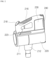
- the second extension 216c may extend from the grip portion to the dust bin 220. At least a part of the second extension 216c may extend in the horizontal direction.
- the manipulation unit 218 may visually display information (e.g., suction strength, a remaining charging level of a battery, and the like) about the operation of the cleaner 200. That is, the manipulation unit 218 may serve as a display device.
- information e.g., suction strength, a remaining charging level of a battery, and the like
- the cleaner 200 may include the dust bin 220.
- the dust bin 220 may communicate with the dust separator 213.
- the dust bin 220 may store the dust separated by the dust separator 213.
- the dust bin 220 may include a dust bin main body 221, a discharging cover 222, a dust bin compression lever 223, and a compression member (not illustrated).
- the dust bin main body 221 may provide a space in which the dust separated by the dust separator 213 may be stored.
- the dust bin main body 221 may be formed in a shape similar to a cylindrical shape.
- the dust bin 220 may include the discharging cover 222.
- the discharging cover 222 may be disposed on the lower surface of the dust bin 220.
- the discharging cover 222 may be provided to open and close one end portion of the dust bin main body 221 in the longitudinal direction. Specifically, the discharging cover 222 may selectively open and close a downward open lower portion of the dust bin 220.
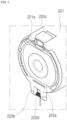
- the discharging cover 222 may include a cover main body 222a and a hinge unit 222b.
- the cover main body 222a may be formed to block a part of the lower surface of the dust bin main body 221.
- the cover main body 222a may rotate downward with respect to the hinge unit 222b.
- the hinge unit 222b may be disposed adjacent to the battery housing 230.
- the hinge unit 222b may be provided with a torsion spring 222d. Accordingly, when the discharging cover 222 is separated from the dust bin main body 221, the cover main body 222a may be supported while rotated about the hinge unit 222b at a predetermined angle or more in the dust bin main body 221 by an elastic force of the torsion spring 222d.
- the compression member (not illustrated) may be disposed inside the dust bin main body 221.
- the compression member may move in an internal space of the dust bin main body 221. Specifically, the compression member may move upward and downward in the dust bin main body 221. Accordingly, the compression member may compress the dust in the dust bin main body 221 downward.
- the compression member may move from the upper portion to the lower portion of the dust bin 220 to remove foreign substances such as the remaining dust in the dust bin 220. Accordingly, it is possible to increase the suction force of the cleaner by preventing the remaining dust from remaining in the dust bin 220.
- bad odors generated by the residue can be removed by preventing the remaining dust from remaining in the dust bin 220.
- the cleaner 200 may include the battery housing 230.
- a battery 240 may be accommodated in the battery housing 230.
- the battery housing 230 may be disposed under the handle 216.
- the battery housing 230 may have a hexahedral shape with an open lower portion.
- a rear surface of the battery housing 230 may be connected to the handle 216.
- the battery housing 230 may include an accommodation portion which is opened downward.
- the battery 240 may be detachably attached through the accommodation portion of the battery housing 230.
- the cleaner 200 may include the battery 240.
- the battery 240 may be detachably coupled to the cleaner 200.
- the battery 240 may be detachably coupled to the battery housing 230.
- the battery 240 may be inserted into the battery housing 230 from the bottom of the battery housing 230. With this configuration, it is possible to improve the portability of the cleaner 200.
- the battery 240 may be provided integrally inside the battery housing 230. In this case, a lower surface of the battery 240 is not exposed to the outside.
- the battery 240 may supply power to the suction motor 214 of the cleaner 200.
- the battery 240 may be disposed under the handle 216.
- the battery 240 may be disposed behind the dust bin 220.
- the lower surface of the battery 240 when the battery 240 is coupled to the battery housing 230, the lower surface of the battery 240 may be exposed to the outside. Since the battery 240 may be disposed on the floor when the cleaner 200 is disposed on the floor, the battery 240 may be immediately separated from the battery housing 230. In addition, since the lower surface of the battery 240 is exposed to the outside and in direct contact with external air of the battery 240, it is possible to improve cooling performance of the battery 240.
- a structure for detachably attaching the battery 240 to the battery housing 230 can be smaller, thereby reducing the overall size of the cleaner 200 and achieving lightweight.
- the cleaner 200 may include the extension pipe 250.
- the extension pipe 250 may communicate with a cleaning module 260.
- the extension pipe 250 may communicate with the main body 210.
- the extension pipe 250 may communicate with the suction unit 212 of the main body 210.
- the extension pipe 250 may be formed in a long cylindrical shape.
- the main body 210 may be connected to the extension pipe 250.
- the main body 210 may be connected to the cleaning module 260 through the extension pipe 250.
- the main body 210 may generate the suction force through the suction motor 214 and provide the suction force to the cleaning module 260 through the extension pipe 250. External dust may flow into the main body 210 through the cleaning module 260 and the extension pipe 250.
- the cleaner 200 may include the cleaning module 260.
- the cleaning module 260 may communicate with the extension pipe 250. Accordingly, external air may pass through the cleaning module 260 and the extension pipe 250 and may be introduced into the main body 210 of the cleaner 200 by the suction force generated from the main body 210 of the cleaner 200.
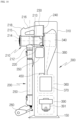
- the dust in the dust bin 220 of the cleaner 200 may be collected in the collection unit 370 of the cleaner station 300 by gravity.
- the dust in the dust bin 220 may be collected in the collection unit 370 of the cleaner station 300 by the suction force of the dust collection motor 391 disposed inside the cleaner station 300. Accordingly, since the dust in the dust bin may be removed without separate manipulation of the user, user convenience can be provided. In addition, it is possible to eliminate the inconvenience of the user having to empty the dust bin every time. In addition, it is possible to prevent dust from scattering when the user empties the dust bin.
- the cleaner 200 may be coupled to a side surface of a housing 310. Specifically, the main body 210 of the cleaner 200 may be caught on a coupling unit 320. More specifically, the dust bin 220 and the battery housing 230 of the cleaner 200 may be coupled to a coupling surface 321 of the coupling unit 320. An outer circumferential surface of the dust bin main body 221 may be coupled to a dust bin guide surface 322. The suction unit 212 may be coupled to the suction unit guide surface 326 of the coupling unit 320. With this configuration, a center axis of the dust bin 220 may be disposed in a direction parallel to the ground, and the extension pipe 250 may be disposed in a direction perpendicular to the ground.
- the cleaner 200 may be coupled to the cleaner station 300.
- the main body of the cleaner 200 may be coupled to the side surface of the cleaner station 300.
- the dust bin 220 of the cleaner 200 may be coupled to the side surface of the cleaner station 300 and coupled through one side at which the discharging cover 222 is disposed. Accordingly, when the discharging cover 222 is opened, the dust in the dust bin 220 may be collected inside the cleaner station 300 and removed.
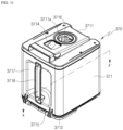
- the cleaner station 300 may include the housing 310.
- the housing 310 may form the exterior of the cleaner station 300.
- the housing 310 may be formed in a pillar shape including at least one outer wall surface.
- the housing 310 may be formed in a shape similar to a quadrangular pillar.
- a space which may accommodate the collection unit 370 and a dust suction module 390, may be formed inside the housing 310.
- the bottom surface 311 may support a lower side of the dust suction module 390 in a direction of gravity. That is, the bottom surface 311 may support the lower side of the dust collection motor 391 of the dust suction module 390.
- the bottom surface 311 may be disposed toward the ground.
- the bottom surface 311 may be not only disposed parallel to the ground, but also disposed to be inclined at a predetermined angle with the ground.
- the bottom surface 311 may further include a ground support 311a which increases an area in contact with the ground to prevent the cleaner station 300 from falling down and maintain balance.
- the ground support 311a may be in the form of a plate extending from the bottom surface 311, and one or more frames may be formed to protrude and extend from the bottom surface 311 toward the ground.
- the outer wall surface 312 may be a surface formed in the direction of gravity and may be a surface connected to the bottom surface 311.
- the outer wall surface 312 may be a surface connected perpendicular to the bottom surface 311.
- the outer wall surface 312 may be disposed to be inclined at a predetermined angle with the bottom surface 311.
- the first outer wall surface 312a may be disposed on a front surface of the cleaner station 300.
- the front surface may be a surface on which the cleaner 200 is exposed in a state in which the cleaner 200 is coupled to the cleaner station 300. Accordingly, the first outer wall surface 312a may form an exterior of the front surface of the cleaner station 300.
Landscapes
- Engineering & Computer Science (AREA)
- Mechanical Engineering (AREA)
- Robotics (AREA)
- Electric Vacuum Cleaner (AREA)
- Filters For Electric Vacuum Cleaners (AREA)
Applications Claiming Priority (2)
| Application Number | Priority Date | Filing Date | Title |
|---|---|---|---|
| KR1020220171652A KR102890120B1 (ko) | 2022-12-09 | 2022-12-09 | 청소기 스테이션 및 청소기 스테이션의 먼지 집진 방법 |
| PCT/KR2023/006992 WO2024122766A1 (ko) | 2022-12-09 | 2023-05-23 | 청소기 스테이션 및 청소기 스테이션의 먼지 집진 방법 |
Publications (1)
| Publication Number | Publication Date |
|---|---|
| EP4581995A1 true EP4581995A1 (de) | 2025-07-09 |
Family
ID=91379508
Family Applications (1)
| Application Number | Title | Priority Date | Filing Date |
|---|---|---|---|
| EP23900790.9A Pending EP4581995A1 (de) | 2022-12-09 | 2023-05-23 | Staubsaugerstation und verfahren zum sammeln von staub mit der staubsaugerstation |
Country Status (5)
| Country | Link |
|---|---|
| EP (1) | EP4581995A1 (de) |
| KR (1) | KR102890120B1 (de) |
| CN (1) | CN119789804A (de) |
| AU (1) | AU2023391498A1 (de) |
| WO (1) | WO2024122766A1 (de) |
Family Cites Families (9)
| Publication number | Priority date | Publication date | Assignee | Title |
|---|---|---|---|---|
| KR100595692B1 (ko) | 2004-11-05 | 2006-07-03 | 엘지전자 주식회사 | 블루투스 통신기능을 구비한 이동통신 단말기 |
| KR100906849B1 (ko) * | 2006-09-06 | 2009-07-08 | 엘지전자 주식회사 | 진공 청소기 및 그의 제어 방법 |
| KR100906848B1 (ko) | 2006-05-20 | 2009-07-08 | 엘지전자 주식회사 | 진공 청소기 |
| KR100871486B1 (ko) * | 2006-02-22 | 2008-12-05 | 엘지전자 주식회사 | 집진장치 및 이를 가지는 진공 청소기 |
| JP4940873B2 (ja) * | 2006-10-04 | 2012-05-30 | パナソニック株式会社 | 電気掃除機 |
| KR101984571B1 (ko) * | 2012-02-09 | 2019-05-31 | 엘지전자 주식회사 | 먼지 압축 기능을 구비하는 로봇청소기 및 그 제어방법 |
| CN107405031B (zh) | 2014-12-24 | 2020-10-02 | 美国 iRobot 公司 | 排空站 |
| KR20220073946A (ko) * | 2020-11-27 | 2022-06-03 | 엘지전자 주식회사 | 청소기 스테이션 |
| KR102440910B1 (ko) * | 2021-01-13 | 2022-09-07 | 엘지전자 주식회사 | 청소기 스테이션, 청소기 시스템 및 그 제어방법 |
-
2022
- 2022-12-09 KR KR1020220171652A patent/KR102890120B1/ko active Active
-
2023
- 2023-05-23 CN CN202380062003.5A patent/CN119789804A/zh active Pending
- 2023-05-23 WO PCT/KR2023/006992 patent/WO2024122766A1/ko not_active Ceased
- 2023-05-23 EP EP23900790.9A patent/EP4581995A1/de active Pending
- 2023-05-23 AU AU2023391498A patent/AU2023391498A1/en active Pending
Also Published As
| Publication number | Publication date |
|---|---|
| KR20240086275A (ko) | 2024-06-18 |
| KR102890120B1 (ko) | 2025-11-25 |
| WO2024122766A1 (ko) | 2024-06-13 |
| AU2023391498A1 (en) | 2025-04-10 |
| CN119789804A (zh) | 2025-04-08 |
Similar Documents
| Publication | Publication Date | Title |
|---|---|---|
| KR102452456B1 (ko) | 진공 청소기와 도킹 스테이션을 포함하는 청소 장치 | |
| KR102440910B1 (ko) | 청소기 스테이션, 청소기 시스템 및 그 제어방법 | |
| KR100869003B1 (ko) | 진공청소기 | |
| EP4573999A1 (de) | Reinigungsstation und staubsammelverfahren für reinigungsstation | |
| EP4403084A1 (de) | Reinigungssystem und steuerungsverfahren dafür | |
| EP4581995A1 (de) | Staubsaugerstation und verfahren zum sammeln von staub mit der staubsaugerstation | |
| EP4403085A1 (de) | Reinigungssystem und steuerungsverfahren dafür | |
| KR20220110709A (ko) | 청소기 스테이션 및 이를 포함하는 청소기 시스템과, 청소기 시스템을 이용한 잔여 먼지 제거 방법 | |
| EP4595855A1 (de) | Staubsaugerstation | |
| TWI835196B (zh) | 吸塵器停靠站 | |
| AU2022306644B2 (en) | Cleaner station | |
| KR102712603B1 (ko) | 청소기 스테이션 | |
| TWI893892B (zh) | 吸塵器系統 | |
| EP4613167A1 (de) | Staubsaugerstation | |
| CN121985897A (en) | Vacuum cleaner system |
Legal Events
| Date | Code | Title | Description |
|---|---|---|---|
| STAA | Information on the status of an ep patent application or granted ep patent |
Free format text: STATUS: THE INTERNATIONAL PUBLICATION HAS BEEN MADE |
|
| PUAI | Public reference made under article 153(3) epc to a published international application that has entered the european phase |
Free format text: ORIGINAL CODE: 0009012 |
|
| STAA | Information on the status of an ep patent application or granted ep patent |
Free format text: STATUS: REQUEST FOR EXAMINATION WAS MADE |
|
| 17P | Request for examination filed |
Effective date: 20250404 |
|
| AK | Designated contracting states |
Kind code of ref document: A1 Designated state(s): AL AT BE BG CH CY CZ DE DK EE ES FI FR GB GR HR HU IE IS IT LI LT LU LV MC ME MK MT NL NO PL PT RO RS SE SI SK SM TR |
|
| RIC1 | Information provided on ipc code assigned before grant |
Ipc: A47L 9/28 20060101AFI20251205BHEP Ipc: A47L 9/10 20060101ALI20251205BHEP Ipc: A47L 7/00 20060101ALI20251205BHEP |
|
| DAV | Request for validation of the european patent (deleted) | ||
| DAX | Request for extension of the european patent (deleted) |