EP4581972A1 - Helm - Google Patents
Helm Download PDFInfo
- Publication number
- EP4581972A1 EP4581972A1 EP25161847.6A EP25161847A EP4581972A1 EP 4581972 A1 EP4581972 A1 EP 4581972A1 EP 25161847 A EP25161847 A EP 25161847A EP 4581972 A1 EP4581972 A1 EP 4581972A1
- Authority
- EP
- European Patent Office
- Prior art keywords
- shell
- helmet
- segments
- segment
- wearer
- Prior art date
- Legal status (The legal status is an assumption and is not a legal conclusion. Google has not performed a legal analysis and makes no representation as to the accuracy of the status listed.)
- Pending
Links
Images





Classifications
-
- A—HUMAN NECESSITIES
- A42—HEADWEAR
- A42B—HATS; HEAD COVERINGS
- A42B3/00—Helmets; Helmet covers ; Other protective head coverings
- A42B3/04—Parts, details or accessories of helmets
- A42B3/06—Impact-absorbing shells, e.g. of crash helmets
-
- A—HUMAN NECESSITIES
- A42—HEADWEAR
- A42B—HATS; HEAD COVERINGS
- A42B3/00—Helmets; Helmet covers ; Other protective head coverings
- A42B3/04—Parts, details or accessories of helmets
- A42B3/06—Impact-absorbing shells, e.g. of crash helmets
- A42B3/062—Impact-absorbing shells, e.g. of crash helmets with reinforcing means
- A42B3/063—Impact-absorbing shells, e.g. of crash helmets with reinforcing means using layered structures
- A42B3/064—Impact-absorbing shells, e.g. of crash helmets with reinforcing means using layered structures with relative movement between layers
-
- A—HUMAN NECESSITIES
- A42—HEADWEAR
- A42B—HATS; HEAD COVERINGS
- A42B3/00—Helmets; Helmet covers ; Other protective head coverings
- A42B3/04—Parts, details or accessories of helmets
- A42B3/10—Linings
- A42B3/12—Cushioning devices
- A42B3/125—Cushioning devices with a padded structure, e.g. foam
- A42B3/127—Cushioning devices with a padded structure, e.g. foam with removable or adjustable pads
Definitions
- the present invention relates to helmets.
- the invention relates to helmets with a plurality of internal shell segments that can slide with respect to each other and also with respect to an outer shell.
- Helmets are known for use in various activities. These activities include combat and industrial purposes, such as protective helmets for soldiers and hard-hats or helmets used by builders, mine-workers, or operators of industrial machinery for example. Helmets are also common in sporting activities. For example, protective helmets may be used in ice hockey, cycling, motorcycling, motor-car racing, skiing, snow-boarding, skating, skateboarding, equestrian activities, American football, baseball, rugby, cricket, lacrosse, climbing, golf, airsoft and paintballing.
- Helmets can be of fixed size or adjustable, to fit different sizes and shapes of head.
- the adjustability can be provided by moving parts of the helmet to change the outer and inner dimensions of the helmet. This can be achieved by having a helmet with two or more parts which can move with respect to each other.
- the helmet is provided with an attachment device for fixing the helmet to the user's head, and it is the attachment device that can vary in dimension to fit the user's head whilst the main body or shell of the helmet remains the same size.
- comfort padding within the helmet can act as the attachment device.
- the attachment device can also be provided in the form of a plurality of physically separate parts, for example a plurality of comfort pads which are not interconnected with each other.
- Such attachment devices for seating the helmet on a user's head may be used together with additional strapping (such as a chin strap) to further secure the helmet in place. Combinations of these adjustment mechanisms are also possible.
- Helmets are often made of an outer shell, that is usually hard and made of a plastic or a composite material, and an energy absorbing layer called a liner.
- a protective helmet has to be designed so as to satisfy certain legal requirements which relate to inter alia the maximum acceleration that may occur in the centre of gravity of the brain at a specified load.
- tests are performed, in which what is known as a dummy skull equipped with a helmet is subjected to a radial blow towards the head. This has resulted in modern helmets having good energy- absorption capacity in the case of blows radially against the skull.
- Progress has also been made (e.g.
- Such oblique impacts result in both translational acceleration and angular acceleration of the brain.
- Angular acceleration causes the brain to rotate within the skull creating injuries on bodily elements connecting the brain to the skull and also to the brain itself.
- rotational injuries include concussion, subdural haematomas (SDH), bleeding as a consequence of blood vessels rapturing, and diffuse axonal injuries (DAI), which can be summarized as nerve fibres being over stretched as a consequence of high shear deformations in the brain tissue.
- SDH subdural haematomas
- DAI diffuse axonal injuries
- SDH SDH
- DAI DAI
- US 2007/0157370 discloses a helmet with an outer shell split into segments, with an internal, continuous, foam liner.
- the out shell segments are joined to the liner so as to allow a slight sliding between the foam liner and at least a part of the shell segments.
- splitting the outer shell into segments potentially allows for the outer shell to be snagged on passing branches etc.
- WO 2015/089646 discloses the use of internal pad members positioned at different locations within a helmet.
- the pad members may have layers that shear with respect to each other.
- the pad members are only present at discrete locations and do not provide a continuous liner within the helmet.
- US 2014/0090155 discloses a helmet in which an inner liner comprises one or more pads.
- an inner liner comprises one or more pads.
- lateral pads at the side of the helmet can slide.
- other pads within the helmet do not slide.
- US 2012/0047635 discloses a helmet with damping elements arranged within a liner. At least some of those damping elements can be attached to the surrounding shell by attaching means of the hook and loop type (i.e. Velcro ® ). As such, this does not allow for any practical sliding between the shell and the damping elements in an impact situation.
- Velcro ® the hook and loop type
- a helmet optionally comprising one or more of: an outer shell; an inner shell lining an inner surface of the outer shell and formed from an energy absorbing material configured to protect against a radial component of an impact to the wearer's head; and a low friction sliding interface between the inner shell and the outer shell configured to facilitate sliding of the inner shell relative to the outer shell in response to an impact to the wearer's head to protect against a tangential component of the impact; wherein the inner shell comprises a plurality of shell segments each shell segment being configured to slide relative to the outer shell at the sliding interface and each shell segment being configured to slide independently of each other shell segment.
- the inner shell By providing the inner shell as a complete liner formed of segments, the entirety of the user's head is protected in the case of oblique impacts. Further, as individual segments can move, without being constrained by regions of the inner shell elsewhere in the helmet, it is possible to more reliably provide the protection against oblique impacts. That is, if for any reason the inner shell is prevented from sliding with respect to the outer shell in one area/segment, other areas/segments will still be able to slide, which may not be possible if the inner shell is provided as a single piece.
- the at least two shell segments can be connected to each other by a connector configured to allow the two shell segments to slide independently of each other.
- the connector allows movement between the two shell segments, such that each can slide with respect to the outer shell without the other segment necessarily sliding with respect to the outer shell (or, at least, not necessarily sliding in the same direction).
- the connector can be arranged between the at least two shell segments.
- the connector can comprise a resilient structure.
- the connector can be a separate component to the at least two shell segments.
- the connector can includes a layer of material connected at an inner or outer surface of the inner shell to the at least two shell segments and which spans a space between the at least two shell segments.
- the connector can be connected at an outer surface of the inner shell and covers the shell segments to form the low friction sliding interface with the outer shell.
- the connector can be a part of the inner shell co-formed with the at least two shell segments between the at least two shell segments and formed so as to have a lower stiffness than the at least two shell segments so as to allow the at least two shell segments to move relative to each other.
- the connector can comprise apertures in the energy absorbing material forming the part of the inner shell configured to provide the lower stiffness of the connector compared to the at least two shell segments, wherein the energy absorbing material defining the apertures forms a resilient structure.
- the apertures can be circular in cross-section.
- the aforementioned resilient structure can comprise at least one angular portion between the at least two shell segments, an angle of said angular portion being configured to change to allow relative movement between the at least two shell segments.
- the resilient structure can comprise at least one inflected portion between the at least two shell segments, an inflection amount of said angular portion being configured to change to allow relative movement between the at least two shell segments.
- the resilient structure can comprise at least one loop-like portion between the at least two shell segments, the shape of said loop-like portion being configured to change to allow relative movement between the at least two shell segments.
- the resilient structure can comprise at least two intersecting parts between the at least two shell segments, an angle at which said at least two intersecting parts intersect being configured to change to allow relative movement between the at least two shell segments.
- the resilient structure can comprise at least straight portion between the at least two shell segments, the straight portion being configured to bend to allow relative movement between the at least two shell segments.
- the helmet can comprise front and rear shell segments arranged to cover front and rear parts of the wearer's head respectively.
- One of the front shell segment or rear shell segment can comprise a protruding portion configured to protrude into a cut-out portion of the other of the front shell segment and the rear shell segment.
- the protruding portion can be surrounded on opposing sides by lateral portions of the one of the front shell segment or rear shell segment comprising the protruding portion wherein the protruding portion and the lateral portions are separated by respective gaps in the one of the front shell segment or rear shell segment comprising the protruding portion.
- a distal edge of the protruding portion cam be arced or flat.
- the front shell segment can be an elongate shell segment extending across the front of the helmet from side to side arranged to cover the wearer's forehead and the rear shell segment is arranged to cover rear, left and right portions of the wearer's head and optionally the crown of the wearer's head.
- the helmet can comprise left and right side shell segments arranged to cover left and right sides the wearer's head respectively.
- the helmet can comprise a central shell segment arranged to cover the crown of the wearer's head.
- One of the front shell segment and the rear shell segment can surround the central shell segment.
- the central shell segment can be oval.
- Adjacent shell segments can have a complementary shape.
- connecting members 5 can be varied (for example, being positioned away from the edge portion, and connecting the outer shell 2 and the inner shell 3 through the sliding layer 4).
- the outer shell 2 is preferably relatively thin and strong so as to withstand impact of various types.
- the outer shell 2 could be made of a polymer material such as polycarbonate (PC), polyvinylchloride (PVC) or acrylonitrile butadiene styrene (ABS) for example.
- the polymer material can be fibre-reinforced, using materials such as glass-fibre, Aramid, Twaron, carbon-fibre or Kevlar.
- Inner shell 3 is designed for absorbing the energy of an impact.
- Other elements of the helmet 1 will absorb that energy to a limited extend (e.g. the hard outer shell 2 or so-called 'comfort padding' provided within the inner shell 3), but that is not their primary purpose and their contribution to the energy absorption is minimal compared to the energy absorption of the inner shell 3.
- comfort padding may be made of 'compressible' materials, and as such considered as 'energy absorbing' in other contexts, it is well recognised in the field of helmets that compressible materials are not necessarily 'energy absorbing' in the sense of absorbing a meaningful amount of energy during an impact, for the purposes of reducing the harm to the wearer of the helmet.
- sliding layer 4 or sliding facilitator for example oil, Teflon, microspheres, air, rubber, polycarbonate (PC), a fabric material such as felt, etc.
- a layer may have a thickness of roughly 0.1-5 mm, but other thicknesses can also be used, depending on the material selected and the performance desired.
- the number of sliding layers and their positioning can also be varied, and an example of this is discussed below (with reference to Fig. 3B ).
- connecting members 5 use can be made of, for example, deformable strips of plastic or metal which are anchored in the outer shell and the inner shell in a suitable manner.
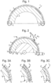
- Fig. 2 shows the functioning principle of protective helmet 1, in which the helmet 1 and a skull 10 of a wearer are assumed to be semi-cylindrical, with the skull 10 being mounted on a longitudinal axis 11. Torsional force and torque are transmitted to the skull 10 when the helmet 1 is subjected to an oblique impact K.
- the impact force K gives rise to both a tangential force K T and a radial force K R against the protective helmet 1.
- only the helmet-rotating tangential force K T and its effect are of interest.
- the force K gives rise to a displacement 12 of the outer shell 2 relative to the inner shell 3, the connecting members 5 being deformed.
- a reduction in the torsional force transmitted to the skull 10 of roughly 25% can be obtained with such an arrangement. This is a result of the sliding motion between the inner shell 3 and the outer shell 2 reducing the amount of energy which is transferred into radial acceleration.
- Sliding motion can also occur in the circumferential direction of the protective helmet 1, although this is not depicted. This can be as a consequence of circumferential angular rotation between the outer shell 2 and the inner shell 3 (i.e. during an impact the outer shell 2 can be rotated by a circumferential angle relative to the inner shell 3).
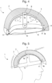
- Fig. 4 depicts a second helmet 1 of the sort discussed in WO 2011/139224 , which is also intended for providing protection against oblique impacts.
- This type of helmet could also be any of the types of helmet discussed above.
- helmet 1 comprises an energy absorbing layer 3, similar to the inner shell 3 of the helmet of Fig. 1 .
- the outer surface of the energy absorbing layer 3 may be provided from the same material as the energy absorbing layer 3 (i.e. there may be no additional outer shell), or the outer surface could be a rigid shell 2 (see Fig. 5 ) equivalent to the outer shell 2 of the helmet shown in Fig. 1 .
- the rigid shell 2 may be made from a different material than the energy absorbing layer 3.
- the helmet 1 of Fig. 4 has a plurality of vents 7, which are optional, extending through both the energy absorbing layer 3 and the outer shell 2, thereby allowing airflow through the helmet 1.
- An attachment device 13 is provided, for attachment of the helmet 1 to a wearer's head. As previously discussed, this may be desirable when energy absorbing layer 3 and rigid shell 2 cannot be adjusted in size, as it allows for the different size heads to be accommodated by adjusting the size of the attachment device 13.
- the attachment device 13 could be made of an elastic or semi-elastic polymer material, such as PC, ABS, PVC or PTFE, or a natural fibre material such as cotton cloth. For example, a cap of textile or a net could form the attachment device 13.
- the attachment device 13 is shown as comprising a headband portion with further strap portions extending from the front, back, left and right sides, the particular configuration of the attachment device 13 can vary according to the configuration of the helmet. In some cases the attachment device may be more like a continuous (shaped) sheet, perhaps with holes or gaps, e.g. corresponding to the positions of vents 7, to allow air-flow through the helmet.
- Fig. 4 also depicts an optional adjustment device 6 for adjusting the diameter of the head band of the attachment device 13 for the particular wearer.
- the head band could be an elastic head band in which case the adjustment device 6 could be excluded.
- a sliding facilitator 4 is provided radially inwards of the energy absorbing layer 3.
- the sliding facilitator 4 is adapted to slide against the energy absorbing layer or against the attachment device 13 that is provided for attaching the helmet to a wearer's head.
- the sliding facilitator 4 is provided to assist sliding of the energy absorbing layer 3 in relation to an attachment device 13, in the same manner as discussed above.
- the sliding facilitator 4 may be a material having a low coefficient of friction, or may be coated with such a material.
- the sliding facilitator may be provided on or integrated with the innermost sided of the energy absorbing layer 3, facing the attachment device 13.
- the sliding facilitator 4 is provided radially inwards of the energy absorbing layer 3.
- the sliding facilitator can also be provided radially outwards of the attachment device 13.
- the attachment device 13 can be fixed to the energy absorbing layer 3 and/ or the outer shell 2 by means of fixing members 5, such as the four fixing members 5a, 5b, 5c and 5d in Fig. 4 .
- fixing members 5 such as the four fixing members 5a, 5b, 5c and 5d in Fig. 4 .
- These may be adapted to absorb energy by deforming in an elastic, semi-elastic or plastic way. However, this is not essential. Further, even where this feature is present, the amount of energy absorbed is usually minimal in comparison to the energy absorbed by the energy absorbing layer 3 during an impact.
- Fig. 5 shows an embodiment of a helmet similar to the helmet in Fig. 4 , when placed on a wearers' head.
- the helmet 1 of Fig. 5 comprises a hard outer shell 2 made from a different material than the energy absorbing layer 3.
- the attachment device 13 is fixed to the energy absorbing layer 3 by means of two fixing members 5a, 5b, which are adapted to absorb energy and forces elastically, semi-elastically or plastically.
- a frontal oblique impact I creating a rotational force to the helmet is shown in Fig. 5 .
- the oblique impact I causes the energy absorbing layer 3 to slide in relation to the attachment device 13.
- the attachment device 13 is fixed to the energy absorbing layer 3 by means of the fixing members 5a, 5b.
- the fixing members 5 can absorb the rotational forces by deforming elastically or semi-elastically. In other arrangements, the deformation may be plastic, even resulting in the severing of one or more of the fixing members 5. In the case of plastic deformation, at least the fixing members 5 will need to be replaced after an impact. In some cases a combination of plastic and elastic deformation in the fixing members 5 may occur, i.e. some fixing members 5 rupture, absorbing energy plastically, whilst other fixing members deform and absorb forces elastically.
- the energy absorbing layer 3 acts as an impact absorber by compressing, in the same way as the inner shell of the Fig. 1 helmet. If an outer shell 2 is used, it will help spread out the impact energy over the energy absorbing layer 3.
- the sliding facilitator 4 will also allow sliding between the attachment device and the energy absorbing layer. This allows for a controlled way to dissipate energy that would otherwise be transmitted as rotational energy to the brain.
- the energy can be dissipated by friction heat, energy absorbing layer deformation or deformation or displacement of the fixing members.
- the reduced energy transmission results in reduced rotational acceleration affecting the brain, thus reducing the rotation of the brain within the skull.
- the risk of rotational injuries such as subdural haematomas, SDH, blood vessel rapturing, concussions and DAI is thereby reduced.
- FIGS. 1-5 depict helmets 1 in which the inner shell/energy absorbing layer 3 is constructed from a single piece.
- helmets 1 having the features depicted in, and described with reference to, Figs. 1-5 may also have a split inner shell 3 as described further below.
- Fig. 6 shows a side view of an inner shell 3 that may be incorporated into a helmet 1 such as depicted in Figs. 1-5 .
- the inner shell 3 can completely line the inner surface of an outer shell 2.
- the inner shell 3 is formed from an energy absorbing material configured to protect against a radial component of an impact to the wearer's head.
- Fig. 6 shows an example of an inner shell 3 which comprises front and rear shell segments 30, which are arranged to cover front and rear parts of the wearer's head respectively.
- the front segment 30 is an elongate shell segment extending across the front of the helmet from side to side arranged to cover the wearer's forehead.
- the rear shell segment 30 is arranged, in this example, to cover rear, left and right portions of the wearer's head and also the crown of the wearer's head.
- the front shells segment 30 could extend to the cover the crown of the wearer's head instead of the back shell segment 30.
- the shell segments 30 can have a complementary shape so that they substantially entirely line the inner surface of the outer shell 2.
- Fig. 7 shows a top view of an alternative arrangement, in which the inner shell 3 incorporates further shell segments 30 (N.B in Fig. 7 , the connectors 20 are not explicitly shown).
- central shell segment 30 arranged to sit at the top of the wearer's head in use i.e. a segment arranged to cover the wearer's crown).
- the rear segment 30 surrounds the central segment 30. These two segments are connected by a connector 20 extending around the periphery of the central segment 30. As such, the central segment 30 is able to move in all directions with respect to the rear segment 30. However, the front segment 30 is only configured to move horizontally (as depicted in Fig. 8B ), so as to move left and right around a wearer's head. In other words, this segment 30 does not move up and down, in use, with respect to the user's eyes. To implement this, connectors 20 are provided at the left and right ends of the front segment 30, but there is no connector between the front and rear segments. Instead, a sliding interface is provided between the front and rear segments.
- Fig 18 also illustrates an attachment point 40 used on the projection from the rear segment 30, which is discussed in more detail with reference to Figs. 11a and 11b below.
- Fig. 9 illustrates how the multiple shell segments 30 may be provided within an actual helmet, in this case an American football helmet.
- the front segment 30 extends across the front of the helmet from side to side, to cover the wearer's forehead, and also extends to cover the wearer's crown.
- the rear shell segment 30 is arranged, in this example, to wrap around from the top of one side, around the back of the head, to the top of the other side.
- Left and right segments are provided to cover the bottom side portions of the wearer's head (the right segment, from the wearer's perspective, is not visible in Fig 9 , due to the orientation of the helmet).
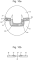
- Figs. 10A and 10B illustrate further detail with respect to the form of the connectors 20.
- Fig. 10A shows a view of an inner shell 3 made up of two shell segments 30, as viewed from the bottom/inside of the shell. That is, there is a front segment 30 comprising a protruding region configured to protrude into a cut-out portion of the rear shell segment.
- the protruding portion is surrounded on opposing sides by lateral portions of the front shell segment 30 (i.e. the segment 30 comprising the protruding portion), and the protruding portion and the lateral portions are separated by gaps in the front shell segment 30.
- the inverse arrangement, with the protruding portion being in the rear part of a rear shell segment 30 is also possible.
- the distal edge of the protruding section can be substantially flat, as shown in Fig. 10A or arced as shown in Fig. 14 for example.
- a connector 20 joins the two shell segments 30.
- Connector 20 in this example includes flange portions 21 which partially overlap with the two shell segments 30.
- the flange portions 21 act as a layer of material that can be connected to the inner or outer surface of the inner shell 3 to the shell segments 30.
- the connector 20 further comprises a resilient structure 22 that connects the flange portions 21, and thus spans the space between the shell segments 30.
- the connector 20 comprises parts 20A, 20B, 20C and 20D each having different forms of the resilient structure 22.
- part 20A has a resilient structure 22 comprising loops, providing apertures within the resilient structure through the loops and between the points where the edge of the loops meet the flanges 21.
- the point of contact between adjacent loops also provides angular portions between the shell segments 30.
- the angle of the angular potions can change, as the shape of the loops are changed by being squashed or stretched, to allow the surrounding shell segments 30 to independently slide with respect to an outer shell 2, by permitting relative movement between the shell segments 30.
- the adjacent loop structure can also be considered as two intersecting wave structures, with the angle of intersection changing to allow relative movement between the shell segments 30.
- the resilient structure 22 comprises a series of substantially rectangular apertures, with struts or straight portions extending between the flanges 21. As shown, the apertures are not perfect rectangles, with the edges of the apertures being slightly curved. This results in the strut portions narrowing towards the centre of the resilient structure 22. This assists with allowing the struts to bend to allow relative movement between the two shell segments 30.
- the resilient member 22 includes some apertures which are triangular rather than quadrilateral. Once again, this results in intersecting struts reaching between the two shell segments 30 (i.e. from one flange 21 to the other). However, in this case, the intersecting parts extend at an angle which again assists with allowing relative movement between the at least two shell segments 30 by allowing bending by changing the angle between the intersecting parts and the surrounding shell segments 30.
- the resilient structure 22 is provided by a series of circular or oval apertures. In a manner similar to that of part 20B, this results in intersecting struts between the two shell segments 30, with those intersecting struts narrowing towards the centre of the resilient structure 22.
- the particular form of the resilient structure 22 can be any structure which allows relative movement between the at least two shell segments to facilitate the shell segments 30 to slide independently of each other with respect to an outer shell 2. This can be done by providing an angular portion between the at least two shell segments, an inflected portion between the at least two shell segments or intersecting parts between the at least two shell segments.
- Fig. 10B shows a cross-section through two adjacent shell segments 30 and a connector 20 connecting the two shell segments 30. It can be seen that the flange 21 is only provided on one side of the shell segment 30, in this example. This is preferably the inner side of the inner shell 3, thereby providing an uninterrupted outer surface to avoid interfering with the sliding interface 4 arranged between the inner shell 3 and the outer shell 2.
- Fig. 10B also shows one method of attaching the connectors 20 to the shell segments 30, by using some form of pin or bolt 23. However, any means for affixing the connector 20 to the shell segments 30 may be used. This can include other types of mechanical fixing means, or chemical fixing means such as the use of an adhesive or glue.
- Figs. 11A and 11B illustrate how an inner shell 3 composed of segments 30 may be attached within the helmet 1.
- Fig. 11A shows a top view of an inner shell 3, which is composed of five shell segments 30, connected by connectors 20.
- Each shell segment 30 is provided with at least one attachment point 40.
- Attachment point 40 can be used to provide a sliding attachment to the surface surrounding the outer surface of the inner shell 3.
- that may be a low friction layer 4 acting as a low friction sliding interface between the inner shell 3 and the outer shell 2.
- the sliding attachment between the inner shell segments 30 and the layer 4 allows for the shell segments 30 to move relative to each other, as well as to slide independently with respect to the outer shell 2 and the sliding facilitator 4.
- the sliding attachment used at attachment points 40 may be any type of appropriate attachment.
- the connectors discussed in PCT/EP2017/055591 may be used. Those connectors provide a pocket on one part to be connected, within which a plate of material can slide. The plate of material is attached to the part to be connected through an appropriate means, resulting in the two sides of the connection being slidingly connected.
- Other methods of attachment could include some form of elastic connection, for example.
- a continuous low friction sliding layer 4 is provided, spanning the gap between two inner shell segments 30.
- the low friction layer 4 can act as the connector 20, without any additional parts. That is, in this example, the low friction layer 4 connects the segments 30 in a way that allows independent sliding of the shell segments 30.
- the shell segments 30 are connected at an outer surface of the inner shell 3 by a layer of material that also covers the inner shell 3 and forms the low friction sliding interface 4 within the outer shell 2.
- Fig. 14 shows an alternative method of providing the connectors 20.
- the connectors are co-formed with the individual inner shell segments 30, such that the segments 30 and the connectors 20 are also created together from the same material.
- the connectors 20 can be areas of relative weakness / lower stiffness compared to the segments 30, and can thus deform to allow relative movement of the shell segments with respect to each other.
- connecting regions 20 can be formed with apertures, e.g. of substantially circular cross-section, passing through them to provide the lower stiffness. The material through which the apertures pass form the resilient structure 22 of the connector 20.
- FIG. 15 Another alternative is shown in Fig. 15 , in which an intermediate shell 50 is provided between the segments 30 of inner shell 3 and the outer shell 2.
- intermediate layer 50 could act as a connector for segments of the inner layer 32, with the segments 30 being relatively fixed to intermediate layer 50.
- the parts of intermediate layer 50 acting as the connectors 20, may be structurally weakened in the same way as illustrated in Fig. 14 , for example, but this is not necessary.
- the low friction sliding interface 4 would be between the intermediate layer 50 and the outer shell 2, and thus between the inner shell 3 and the outer shell 2.
- the segments 30 of the inner shell 3 may be able to slide relative to the intermediate shell 50.
- separate connectors 20 may be provided between the segments of inner shell 50.
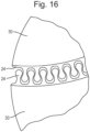
- Fig. 16 illustrates a type of connector 24 made up of two interlocking pieces.
- the interlocking connector pieces 24 may be made of elastic and/or flexible material.
- the segments 30 may be made of a foam material, whilst the connector pieces 24 are made of a more solid, but still flexible, plastic material. That allows one of the pieces 24 to be attached to each of the neighbouring segments 30 (e.g. by any means for affixing, as discussed in connection with the connector 20 of Fig. 10b ) and then the two pieces 24 to be snapped/clicked together.
- the connector pieces 24 When the connector pieces 24 are in the interlocked arrangement, they function like the previously discussed connectors 20 to allow relative movement between the two shell segments 30.
Landscapes
- Helmets And Other Head Coverings (AREA)
Applications Claiming Priority (4)
| Application Number | Priority Date | Filing Date | Title |
|---|---|---|---|
| GBGB1717190.1A GB201717190D0 (en) | 2017-10-19 | 2017-10-19 | Helmet |
| GBGB1800186.7A GB201800186D0 (en) | 2018-01-05 | 2018-01-05 | Helmet |
| PCT/EP2018/077491 WO2019076689A1 (en) | 2017-10-19 | 2018-10-09 | HELMET |
| EP18785587.9A EP3697242B1 (de) | 2017-10-19 | 2018-10-09 | Helm |
Related Parent Applications (2)
| Application Number | Title | Priority Date | Filing Date |
|---|---|---|---|
| EP18785587.9A Division EP3697242B1 (de) | 2017-10-19 | 2018-10-09 | Helm |
| EP18785587.9A Division-Into EP3697242B1 (de) | 2017-10-19 | 2018-10-09 | Helm |
Publications (1)
| Publication Number | Publication Date |
|---|---|
| EP4581972A1 true EP4581972A1 (de) | 2025-07-09 |
Family
ID=63834017
Family Applications (2)
| Application Number | Title | Priority Date | Filing Date |
|---|---|---|---|
| EP25161847.6A Pending EP4581972A1 (de) | 2017-10-19 | 2018-10-09 | Helm |
| EP18785587.9A Active EP3697242B1 (de) | 2017-10-19 | 2018-10-09 | Helm |
Family Applications After (1)
| Application Number | Title | Priority Date | Filing Date |
|---|---|---|---|
| EP18785587.9A Active EP3697242B1 (de) | 2017-10-19 | 2018-10-09 | Helm |
Country Status (8)
| Country | Link |
|---|---|
| US (1) | US11839254B2 (de) |
| EP (2) | EP4581972A1 (de) |
| JP (1) | JP7047112B2 (de) |
| CN (1) | CN111511239B (de) |
| CA (1) | CA3079284C (de) |
| ES (1) | ES3024634T3 (de) |
| TW (1) | TWI712371B (de) |
| WO (1) | WO2019076689A1 (de) |
Families Citing this family (13)
| Publication number | Priority date | Publication date | Assignee | Title |
|---|---|---|---|---|
| CN111565805B (zh) | 2017-11-01 | 2023-02-28 | 反普通私人有限公司 | 冲击保护系统 |
| KR102142990B1 (ko) * | 2020-01-03 | 2020-08-10 | 주식회사 네이처모빌리티 | 가변형 헬멧 |
| US20210378342A1 (en) * | 2020-06-08 | 2021-12-09 | Impact Technologies, Llc | Headgear assemblies and headgear liners having friction-reducing interface elements |
| USD1115179S1 (en) | 2020-09-23 | 2026-02-24 | Studson, Inc. | Protective helmet |
| USD995924S1 (en) | 2021-03-17 | 2023-08-15 | Studson, Inc. | Protective helmet |
| USD995925S1 (en) | 2020-09-23 | 2023-08-15 | Studson, Inc. | Protective helmet |
| USD1004850S1 (en) | 2021-03-17 | 2023-11-14 | Studson, Inc. | Protective helmet |
| TWI752869B (zh) * | 2021-04-21 | 2022-01-11 | 陳重光 | 一種用於作為頭盔內襯之結構 |
| GB202107484D0 (en) * | 2021-05-26 | 2021-07-07 | Mips Ab | Shell, kit, helmet and methods of manufacture of a shell |
| WO2023106453A1 (ko) * | 2021-12-09 | 2023-06-15 | 김병진 | 야구 경기용 헬멧 |
| GB202215847D0 (en) * | 2022-10-26 | 2022-12-07 | Mips Ab | Part of a protective apparatus and protective apparatus |
| US20240324710A1 (en) * | 2023-03-27 | 2024-10-03 | Michael Horgan | Helmet |
| WO2025104347A1 (en) * | 2023-11-16 | 2025-05-22 | Hexr Ltd | Protection device with a reactive structure |
Citations (9)
| Publication number | Priority date | Publication date | Assignee | Title |
|---|---|---|---|---|
| WO2001045526A1 (en) | 1998-06-23 | 2001-06-28 | Neuroprevention Scandinavia Ab | Protective helmet |
| US20040117896A1 (en) * | 2002-10-04 | 2004-06-24 | Madey Steven M. | Load diversion method and apparatus for head protective devices |
| US20060059606A1 (en) * | 2004-09-22 | 2006-03-23 | Xenith Athletics, Inc. | Multilayer air-cushion shell with energy-absorbing layer for use in the construction of protective headgear |
| US20070157370A1 (en) | 2004-01-28 | 2007-07-12 | Pascal Joubert Des Ouches | Semi-rigid protective helmet |
| WO2011139224A1 (en) | 2010-05-07 | 2011-11-10 | Mips Ab | Helmet with sliding facilitator arranged at energy absorbing layer |
| US20120047635A1 (en) | 2009-02-13 | 2012-03-01 | Kuji Sports Ltd | Deformable safety helmet |
| US20140090155A1 (en) | 2011-05-05 | 2014-04-03 | James Michael Johnston | Systems and methods for attenuating rotational acceleration of the head |
| US20150157083A1 (en) * | 2013-12-06 | 2015-06-11 | Bell Sports, Inc. | Multi-layer helmet and method for making the same |
| WO2015089646A1 (en) | 2013-12-19 | 2015-06-25 | Bauer Hockey Corp. | Helmet for impact protection |
Family Cites Families (22)
| Publication number | Priority date | Publication date | Assignee | Title |
|---|---|---|---|---|
| US6292952B1 (en) * | 1998-09-25 | 2001-09-25 | Sportscope, Inc. | Insert-molded helmet |
| US6681403B2 (en) * | 2000-03-13 | 2004-01-27 | Robert M. Lyden | Shin-guard, helmet, and articles of protective equipment including light cure material |
| DE10020300A1 (de) * | 2000-04-26 | 2001-10-31 | Plim Cooperation Ltd | Einstellbarer Helm |
| US6996856B2 (en) * | 2002-09-09 | 2006-02-14 | Puchalski Ione G | Protective head covering having impact absorbing crumple zone |
| ES2326250B1 (es) * | 2007-11-15 | 2010-06-01 | Taexpa, S.L. | Sistema de amortiguacion direccionable para cuerpos receptores de presiones o impactos. |
| US20090260133A1 (en) | 2008-04-18 | 2009-10-22 | Del Rosario John A | Impact Absorbing Frame and Layered Structure System for Safety Helmets |
| SE536246C2 (sv) * | 2010-01-13 | 2013-07-16 | Mips Ab | Mellanliggande lager av friktionsminskande material |
| DE112011104130A5 (de) * | 2010-09-09 | 2013-09-12 | Oliver Schimpf | Schutzhelm; Verfahren zur Verminderung oder Verhinderung einer Kopfverletzung |
| WO2012109381A1 (en) | 2011-02-09 | 2012-08-16 | Innovation Dynamics LLC | Helmet omnidirectional energy management systems |
| WO2013000095A1 (en) | 2011-06-30 | 2013-01-03 | Simon Fraser University | Impact diverting mechanism |
| CA2784316C (en) | 2011-07-27 | 2013-10-01 | Bauer Hockey Corp. | Sports helmet with rotational impact protection |
| US10178889B2 (en) | 2011-08-01 | 2019-01-15 | Brian Wacter | Customizable head protection |
| US20130174329A1 (en) * | 2012-01-10 | 2013-07-11 | Poc Ventures | Protective Helmet Cap |
| US10149511B2 (en) | 2012-09-28 | 2018-12-11 | Matscitechno Licensing Company | Protective headgear system |
| US10039335B2 (en) * | 2012-11-29 | 2018-08-07 | Bell Sports, Inc. | Multi-component helmet construction |
| US9924756B2 (en) * | 2013-12-09 | 2018-03-27 | Stephen Craig Hyman | Total contact helmet |
| JP6715846B2 (ja) | 2014-12-23 | 2020-07-01 | サフィーロ・ソシエタ・アツィオナリア・ファブリカ・イタリアナ・ラボラツィオーネ・オッチアリ・エス・ピー・エー | スポーツ用、特にスキーをするときに使用する保護ヘルメット |
| EP3117726B1 (de) | 2015-07-17 | 2018-07-18 | Anomaly Action Sports S.r.l. | Schutzhelm |
| US9961952B2 (en) | 2015-08-17 | 2018-05-08 | Bauer Hockey, Llc | Helmet for impact protection |
| US20170188648A1 (en) | 2016-01-06 | 2017-07-06 | Geoffrey Paul Larrabee | Layered Helmet |
| CN205456344U (zh) | 2016-01-22 | 2016-08-17 | 王众北 | 一种新型的防御头盔 |
| US10342280B2 (en) * | 2017-11-30 | 2019-07-09 | Diffusion Technology Research, LLC | Protective helmet |
-
2018
- 2018-10-09 ES ES18785587T patent/ES3024634T3/es active Active
- 2018-10-09 EP EP25161847.6A patent/EP4581972A1/de active Pending
- 2018-10-09 JP JP2020542502A patent/JP7047112B2/ja active Active
- 2018-10-09 EP EP18785587.9A patent/EP3697242B1/de active Active
- 2018-10-09 WO PCT/EP2018/077491 patent/WO2019076689A1/en not_active Ceased
- 2018-10-09 US US16/757,085 patent/US11839254B2/en active Active
- 2018-10-09 CN CN201880068521.7A patent/CN111511239B/zh active Active
- 2018-10-09 CA CA3079284A patent/CA3079284C/en active Active
- 2018-10-19 TW TW107136886A patent/TWI712371B/zh active
Patent Citations (9)
| Publication number | Priority date | Publication date | Assignee | Title |
|---|---|---|---|---|
| WO2001045526A1 (en) | 1998-06-23 | 2001-06-28 | Neuroprevention Scandinavia Ab | Protective helmet |
| US20040117896A1 (en) * | 2002-10-04 | 2004-06-24 | Madey Steven M. | Load diversion method and apparatus for head protective devices |
| US20070157370A1 (en) | 2004-01-28 | 2007-07-12 | Pascal Joubert Des Ouches | Semi-rigid protective helmet |
| US20060059606A1 (en) * | 2004-09-22 | 2006-03-23 | Xenith Athletics, Inc. | Multilayer air-cushion shell with energy-absorbing layer for use in the construction of protective headgear |
| US20120047635A1 (en) | 2009-02-13 | 2012-03-01 | Kuji Sports Ltd | Deformable safety helmet |
| WO2011139224A1 (en) | 2010-05-07 | 2011-11-10 | Mips Ab | Helmet with sliding facilitator arranged at energy absorbing layer |
| US20140090155A1 (en) | 2011-05-05 | 2014-04-03 | James Michael Johnston | Systems and methods for attenuating rotational acceleration of the head |
| US20150157083A1 (en) * | 2013-12-06 | 2015-06-11 | Bell Sports, Inc. | Multi-layer helmet and method for making the same |
| WO2015089646A1 (en) | 2013-12-19 | 2015-06-25 | Bauer Hockey Corp. | Helmet for impact protection |
Also Published As
| Publication number | Publication date |
|---|---|
| EP3697242C0 (de) | 2025-04-16 |
| ES3024634T3 (en) | 2025-06-04 |
| WO2019076689A1 (en) | 2019-04-25 |
| US20200260813A1 (en) | 2020-08-20 |
| TWI712371B (zh) | 2020-12-11 |
| TW201922128A (zh) | 2019-06-16 |
| CA3079284A1 (en) | 2019-04-25 |
| CN111511239A (zh) | 2020-08-07 |
| JP2020537718A (ja) | 2020-12-24 |
| US11839254B2 (en) | 2023-12-12 |
| JP7047112B2 (ja) | 2022-04-04 |
| EP3697242B1 (de) | 2025-04-16 |
| CN111511239B (zh) | 2023-03-28 |
| CA3079284C (en) | 2023-09-19 |
| EP3697242A1 (de) | 2020-08-26 |
Similar Documents
| Publication | Publication Date | Title |
|---|---|---|
| EP3697242B1 (de) | Helm | |
| EP3256016B1 (de) | Helm, auskleidung für helm, komfortpolsterung für einen helm und verbinder | |
| EP3481244B1 (de) | Verbinder | |
| US11771167B2 (en) | Connector | |
| EP3876776B1 (de) | Verbinder | |
| US12256796B2 (en) | Helmet | |
| US20220071332A1 (en) | Connector for helmet and helmet including such a connector | |
| EP3873286B1 (de) | Wangenpolster für helm |
Legal Events
| Date | Code | Title | Description |
|---|---|---|---|
| PUAI | Public reference made under article 153(3) epc to a published international application that has entered the european phase |
Free format text: ORIGINAL CODE: 0009012 |
|
| STAA | Information on the status of an ep patent application or granted ep patent |
Free format text: STATUS: THE APPLICATION HAS BEEN PUBLISHED |
|
| AC | Divisional application: reference to earlier application |
Ref document number: 3697242 Country of ref document: EP Kind code of ref document: P |
|
| AK | Designated contracting states |
Kind code of ref document: A1 Designated state(s): AL AT BE BG CH CY CZ DE DK EE ES FI FR GB GR HR HU IE IS IT LI LT LU LV MC MK MT NL NO PL PT RO RS SE SI SK SM TR |
|
| STAA | Information on the status of an ep patent application or granted ep patent |
Free format text: STATUS: REQUEST FOR EXAMINATION WAS MADE |
|
| 17P | Request for examination filed |
Effective date: 20250930 |
|
| STAA | Information on the status of an ep patent application or granted ep patent |
Free format text: STATUS: EXAMINATION IS IN PROGRESS |
|
| 17Q | First examination report despatched |
Effective date: 20260522 |