EP4581951A1 - Electronic atomization device, power source mechanism for electronic atomization device, and circuit board - Google Patents
Electronic atomization device, power source mechanism for electronic atomization device, and circuit board Download PDFInfo
- Publication number
- EP4581951A1 EP4581951A1 EP23876521.8A EP23876521A EP4581951A1 EP 4581951 A1 EP4581951 A1 EP 4581951A1 EP 23876521 A EP23876521 A EP 23876521A EP 4581951 A1 EP4581951 A1 EP 4581951A1
- Authority
- EP
- European Patent Office
- Prior art keywords
- atomization device
- electronic atomization
- battery cell
- circuit board
- extending
- Prior art date
- Legal status (The legal status is an assumption and is not a legal conclusion. Google has not performed a legal analysis and makes no representation as to the accuracy of the status listed.)
- Pending
Links
Images








Classifications
-
- A—HUMAN NECESSITIES
- A24—TOBACCO; CIGARS; CIGARETTES; SIMULATED SMOKING DEVICES; SMOKERS' REQUISITES
- A24F—SMOKERS' REQUISITES; MATCH BOXES; SIMULATED SMOKING DEVICES
- A24F40/00—Electrically operated smoking devices; Component parts thereof; Manufacture thereof; Maintenance or testing thereof; Charging means specially adapted therefor
- A24F40/40—Constructional details, e.g. connection of cartridges and battery parts
- A24F40/46—Shape or structure of electric heating means
-
- A—HUMAN NECESSITIES
- A24—TOBACCO; CIGARS; CIGARETTES; SIMULATED SMOKING DEVICES; SMOKERS' REQUISITES
- A24F—SMOKERS' REQUISITES; MATCH BOXES; SIMULATED SMOKING DEVICES
- A24F40/00—Electrically operated smoking devices; Component parts thereof; Manufacture thereof; Maintenance or testing thereof; Charging means specially adapted therefor
- A24F40/40—Constructional details, e.g. connection of cartridges and battery parts
-
- A—HUMAN NECESSITIES
- A24—TOBACCO; CIGARS; CIGARETTES; SIMULATED SMOKING DEVICES; SMOKERS' REQUISITES
- A24F—SMOKERS' REQUISITES; MATCH BOXES; SIMULATED SMOKING DEVICES
- A24F40/00—Electrically operated smoking devices; Component parts thereof; Manufacture thereof; Maintenance or testing thereof; Charging means specially adapted therefor
- A24F40/50—Control or monitoring
- A24F40/51—Arrangement of sensors
-
- H—ELECTRICITY
- H05—ELECTRIC TECHNIQUES NOT OTHERWISE PROVIDED FOR
- H05K—PRINTED CIRCUITS; CASINGS OR CONSTRUCTIONAL DETAILS OF ELECTRIC APPARATUS; MANUFACTURE OF ASSEMBLAGES OF ELECTRICAL COMPONENTS
- H05K1/00—Printed circuits
- H05K1/02—Details
- H05K1/0277—Bendability or stretchability details
- H05K1/0278—Rigid circuit boards or rigid supports of circuit boards locally made bendable, e.g. by removal or replacement of material
-
- H—ELECTRICITY
- H05—ELECTRIC TECHNIQUES NOT OTHERWISE PROVIDED FOR
- H05K—PRINTED CIRCUITS; CASINGS OR CONSTRUCTIONAL DETAILS OF ELECTRIC APPARATUS; MANUFACTURE OF ASSEMBLAGES OF ELECTRICAL COMPONENTS
- H05K1/00—Printed circuits
- H05K1/02—Details
- H05K1/14—Structural association of two or more printed circuits
- H05K1/147—Structural association of two or more printed circuits at least one of the printed circuits being bent or folded, e.g. by using a flexible printed circuit
-
- A—HUMAN NECESSITIES
- A24—TOBACCO; CIGARS; CIGARETTES; SIMULATED SMOKING DEVICES; SMOKERS' REQUISITES
- A24F—SMOKERS' REQUISITES; MATCH BOXES; SIMULATED SMOKING DEVICES
- A24F40/00—Electrically operated smoking devices; Component parts thereof; Manufacture thereof; Maintenance or testing thereof; Charging means specially adapted therefor
- A24F40/10—Devices using liquid inhalable precursors
-
- A—HUMAN NECESSITIES
- A24—TOBACCO; CIGARS; CIGARETTES; SIMULATED SMOKING DEVICES; SMOKERS' REQUISITES
- A24F—SMOKERS' REQUISITES; MATCH BOXES; SIMULATED SMOKING DEVICES
- A24F40/00—Electrically operated smoking devices; Component parts thereof; Manufacture thereof; Maintenance or testing thereof; Charging means specially adapted therefor
- A24F40/90—Arrangements or methods specially adapted for charging batteries thereof
Definitions
- Embodiments of the present application relate to the field of electronic atomization technologies, and in particular, to an electronic atomization device, a power supply mechanism for the electronic atomization device, and a circuit board for the electronic atomization device.
- an example of such products is a heating device, which releases compounds by heating rather than burning materials.
- the material may be tobacco or other non-tobacco products. These non-tobacco products may or may not include nicotine.
- aerosol-providing articles are provided, for example, a so-called electronic atomization device. These electronic atomization devices usually include a liquid aerosol-forming matrix. The liquid aerosol-forming matrix is heated to be atomized, thus forming an inhalable aerosol.
- the electronic atomization device includes a near end and a far end which face away from each other in a length direction, where the third portion is closer to the far end than the second portion.
- the second portion and/or the third portion are substantially perpendicular to the first portion.
- the second portion and the third portion are perpendicular to each other; alternatively, the second portion and the third portion are parallel to each other.
- any two of the first portion, the second portion, and the third portion are perpendicular to each other.
- the electronic atomization device further includes:
- the electronic atomization device further includes: a first air hole, penetrating through two opposite sides of the second portion, to provide a channel for communicating the first sensing surface to the airflow of the air channel, where the first sensing surface covers the first air hole.
- the air channel includes: a first channel portion close to the first sensing surface and a second channel portion facing away from the first sensing surface; and an angle is formed between the first channel portion and the second channel portion, or the first channel portion and the second channel portion are vertically arranged.
- the air channel includes: a first channel portion close to the first sensing surface and a second channel portion facing away from the first sensing surface; and a cross-sectional area of the first channel portion is smaller than a cross-sectional area of the second channel portion.
- the seal element at least includes:
- the seal element further includes:
- the second air hole deviates from a center of the seal element.
- the seal element at least partially extends into the air channel.
- the seal element includes:
- the electronic atomization device includes:
- a distance between the retaining wall and the first side is greater than a distance between the retaining wall and the second side.
- a distance between the retaining wall and the first side is between 10 mm and 20 mm; and/or a distance between the retaining wall and the second side is between 5 mm and 10 mm.
- the electronic atomization device further includes: a fastening component, at least partially accommodated between the first portion and the second side, to securely press the first portion against the retaining wall.
- At least one convex post extending toward the second side is arranged on the retaining wall; and a hole through which the convex post passes is provided in the first portion.
- Another embodiment of the present application further provides an electronic atomization device, including a first side and a second side which face away from each other in a width direction, and:
- Another embodiment of the present application further provides an electronic atomization device, including a first side and a second side which face away from each other in a width direction, and:
- Another embodiment of the present application further provides an electronic atomization device, including a first side and a second side which face away from each other in a width direction, and:
- Another embodiment of the present application further provides an electronic atomization device, including a first side and a second side which face away from each other in a width direction, and:
- Another embodiment of the present application further provides an electronic atomization device, including a first side and a second side which face away from each other in a width direction, and:
- Still another embodiment of the present application further provides power supply mechanism for an electronic atomization device, configured to supply power to the electronic atomization device, and including a first side and a second side which face away from each other in a width direction, and:
- Yet another embodiment of the present application further provides a circuit board for the electronic atomization device, having a first end and a second end that deviate from each other in a length direction, and a first side and a second side that extend between the first end and the second end and deviate from each other, where the circuit board includes:
- the circuit board assembly is divided into a plurality of portions, which is advantageous for preparation and assembling.
- An embodiment of the present application provides an electronic atomization device, configured to heat a liquid aerosol-forming matrix to form an aerosol for inhalation.
- the aerosol-forming matrix may be a solid or a colloid.
- the electronic atomization device includes an atomizer 100 for storing a liquid aerosol-forming matrix and atomizing the liquid aerosol-forming matrix to form an aerosol, and a power supply mechanism 200 for supplying power to the atomizer 100.
- the atomizer 100 includes:
- the power supply mechanism 200 includes: a receiving cavity 27 arranged at one end in a length direction and configured to receive and accommodate at least a portion of the atomizer 100; and an electrical contact 23 at least partially exposed out of a surface of the receiving cavity 27 and configured to supply power to the atomizer 100 when at least a portion of the atomizer 100 is received and accommodated in the power supply mechanism 200.
- the electrical contact 11 is arranged at an end portion of the atomizer 100 opposite to the power supply mechanism 200 in the length direction, so that when at least a portion of the atomizer 100 is received in the receiving cavity 27, the electrical contact 11 is in contact with and abuts against the electrical contact 23 to conduct electricity.
- a seal element 26 is arranged in the power supply mechanism 200, and at least a portion of an internal space of the power supply mechanism 200 is separated through the seal element 26 to form the above receiving cavity 27.
- the seal element 26 is configured to extend in a cross section direction of the power supply mechanism 200, and is optionally prepared by using a flexible material such as silica gel, so as to prevent the liquid aerosol-forming matrix seeping from the atomizer 100 to the receiving cavity 27 from flowing into the power supply mechanism 200.
- the power supply mechanism 200 further includes a battery cell 21 for supplying power; and a circuit board assembly 30, which operably guides a current between the battery cell 21 and the electrical contact 23.
- a length dimension d11 of the shell 210 is between 70 mm and 100 mm.
- a width dimension d21 of the shell 210 is between 15 mm and 25 mm.
- a thickness dimension d31 of the shell 210 is between 8 mm and 15 mm.
- the shell 210 further includes: a first side 2130 and a second side 2140 that face away from each other in a width direction.
- the shell 210 is provided with: an air inlet 213, configured to allow, when a user puffs on the atomizer 100, external air to enter the receiving cavity 27 and further enter the atomizer 100, as shown by arrow R2 in FIG. 2 and FIG. 3 .
- the air inlet 213 is located on or arranged on the first side 2130 and/or the second side 2140.
- the air inlet 213 in the width direction of the power supply mechanism 200, the air inlet 213 is substantially flush with an end portion of the receiving cavity 27 that faces away from the near end 2110.
- the shell 210 is provided with: an input element 211 operated by a user to form an input signal. Then, the power supply mechanism 200 selectively switches between a locked state and an unlocked state according to the input signal of the user. For example, in the locked state, the power supply mechanism 200 is prevented from outputting power to the atomizer 100, and in the unlocked state, the power supply mechanism 200 is allowed to output power to the atomizer 100.
- the input element 211 is selected from a mechanical button, a film button, a mechanical switch, a rotary encoder, a dial, a knob, a capacitive touch button, a resistive touch button, an operating lever, a slider, a trigger button, a touch screen, and a magnetic switch.
- the input element 211 is, for example, a mechanical button.
- the power supply mechanism 200 controls, according to an input signal of the input element 211, for example, a pressing action or event performed by a user using the mechanical button, to lock or unlock the power supply mechanism 200.
- the shell 210 is provided with: a light source hole 212, configured to allow light emitted by a light source 41 to pass through the shell 210 through the light source hole 212, so as to be received by a user.
- a user may observe a light-emitting state of the light source 41 through the light source hole 212, to determine a current battery level of the power supply mechanism 200.
- a plurality of light sources 41 are provided.
- One or more of the light sources 41 may be turned on to emit light, to prompt a user of different battery levels of the power supply mechanism 200.
- four light sources 41 are provided, which are arranged in sequence in the length direction.
- the four light sources 41 may be made to emit light simultaneously, so as to inform a user that a current battery level is full or is relatively sufficient.
- only one of the light sources 41 is made to emit light, to inform the user that a current battery level is low, so as to prompt the user of charging.
- only two or three of the light sources 41 may be made to emit light simultaneously, to prompt the user of a current battery level.
- the light sources 41 include light-emitting diodes (LEDs).
- the input element 211 and the light source hole 212 are both arranged on the second side 2140. In some embodiments, the light source hole 212 is closer to the near end 2110 than the input element 211. In addition, the input element 211 and the light source hole 212 avoid the receiving cavity 27. Alternatively, the input element 211 and the light source hole 212 are closer to the far end 2120 than the receiving cavity 27.
- the power supply mechanism 200 includes: a battery cell 21, configured to supply power.
- the battery cell 21 is a direct current battery cell.
- a direct current supply voltage provided by the battery cell 21 ranges from about 2.5 V to about 9.0 V, and a direct current provided by the battery cell 21 ranges from about 2.5 A to about 20 A.
- a direct current supply voltage provided by the battery cell 21 ranges from 3.5V to about 5.0V.
- the power supply mechanism 200 includes: a support 250, configured to provide a support for the components in the shell 210.
- the support 250 is configured to be a lengthwise shape extending inside the shell 210 in the length direction of the power supply mechanism 200.
- the support 250 is moulded by a mouldable material such as an organic polymer.
- the organic polymer is, for example, various types of plastic (e.g. polycarbonate and PEEK).
- the support 250 includes: a first support part 251, a second support part 252, and a third support part 253 which are arranged in sequence in the length direction.
- the first support part 251 is close to the near end 2110, and the third support part 253 is close to the far end 2120.
- One side of the second support part 252 facing or close to the front side 2150 and one side of the third support part 253 facing or close to the front side 2150 are provided with openings or are opened.
- the first support part 251 is perpendicular to the length direction.
- the first support part 251 is configured to support and maintain the electrical contact 23.
- the second support part 252 is configured to at least partially accommodate and maintain the battery cell 21.
- the third support part 253 is configured to at least partially accommodate and maintain the charging interface 24.
- the first support part 251 is further configured to support and maintain the seal element 26.
- the seal element 26 may surround or encircle an end surface or a peripheral side surface of the first support part 251 that faces the near end 2110.
- the first support part 251 is provided with a groove 2511 surrounding the first support part 251 in a circumferential direction.
- the seal element 26 may be an annular silicon ring or the like. The first support part 251 is enclosed and sleeved in the groove 2511, to provide sealing between the shell 210 and the first support part 251.
- the electrical contact 23 is a conductive elastic pin extending in the length direction of the power supply mechanism 200.
- the electrical contact 23 is at least partially compressible.
- the electrical contact 23 is maintained on the first support part 251, so as to be supported by the first support part 251.
- the support 250 is directly integrally moulded around the electrical contact 23.
- the electrical contact 23 passes through the first support part 251 in the length direction of the power supply mechanism 200. The electrical contact 23 passes through from one side of the first support part 251 facing or close to the near end 2110 to the other side in the length direction of the power supply mechanism 200.
- the first support part 251 is provided with a contact hole 2512 that passes through from one side of the first support part 251 facing or close to the near end 2110 to the other side, and the electrical contact 23 is at least partially accommodated and maintained in the contact hole 2512.
- a groove 2514 is further arranged on one side of the first support part 251 facing the near end 2110, to accommodate and maintain a magnetic element 28.
- the magnetic element 28 When the atomizer 100 is at least partially received in the receiving cavity 27, the magnetic element 28 is in magnetic attraction with the atomizer 100, so that the atomizer 100 is stably received in the receiving cavity 27.
- the magnetic element 28 is, for example, a magnetic body or a magnetic metal that is in magnetic attraction with a magnetic body.
- the second support part 252 is opened toward or close to the front side 2150, and the battery cell 21 is at least partially accommodated and maintained in the second support part 252.
- the third support part 253 is opened toward or close to the front side 2150, and the charging interface 24 is at least partially accommodated and maintained in the second support part 253.
- the support 250 is further provided with a partition wall 2535 extending in a direction perpendicular to the length direction, and the second support part 252 and the third support part 253 are separated and defined by the partition wall 2535.
- the partition wall 2535 has an upper side surface facing the second support part 252 and a lower side surface facing the third support part 253.
- the support 250 is further provided with a spacing space 254 defined between the first support part 251 and the second support part 252.
- the spacing space 254 is configured to partially accommodate and maintain a portion of the circuit board assembly 30.
- the sensor 50 is mounted or arranged in the spacing space 254.
- the power supply mechanism 200 includes: a charging circuit board 60 which is thin and sheet-like or plate-like.
- the charging circuit board 60 is, for example, a hard printed circuit board (PCB) or a soft PCB board.
- the charging interface 24 is directly fixed or fastened on the charging circuit board 60 in a soldered manner or the like.
- the charging circuit board 60 is provided with: a battery cell connection portion 64, which is, for example, a bonding pad or an electrical contact, and is configured to solder a positive electrode/a negative electrode of the battery cell 21 for connection to conduct electricity.
- the battery cell connection portion 64 is connected to the charging interface 24 through a conductive line printed or arranged on the charging circuit board 60, so that during use, the charging interface 24 is connected to a positive electrode/negative electrode of the battery cell 21 through the conductive line on the charging circuit board 60 to form electrical conduction, to charge the battery cell 21.
- the battery cell connection portion 64 is located on one side of the charging circuit board 60 facing away from the charging interface 24.
- the battery cell connection portion 64 has a shape or a color different from that of another portion on a surface of the charging circuit board 60, which is advantageous for being identified and located by a device such as a color sensor or human eyes.
- the battery cell connection portion 64 is silver or a silver gray, and another portion on the surface of the charging circuit board 60 is green.
- the charging circuit board 60 is provided with: a charging integrated circuit (IC), for example, a common L4066 charging IC, a charging IC (SimTech), a CV1055P charging IC, an S083 charging IC prepared by using a single ASIC, and the like.
- IC charging integrated circuit
- the charging IC is configured to monitor and control charging on the battery cell 21.
- the charging circuit board 60 is maintained at the third support part 253 of the support 250. Moreover, after assembling, the charging interface 24 is covered or blocked by the charging circuit board 60 at the opening of the third support part 253.
- the charging circuit board 60 is fastened to the third support part 253 through a fastening component.
- a screw base 2531 and a screw seat 2532 are arranged on the third support part 253 of the support 250.
- the charging circuit board 60 is provided with a screw hole 61 and a screw hole 62.
- a screw 611 is connected to the screw seat 2531 through the screw hole 61
- a screw 621 is connected to the screw seat 2532 through the screw hole 62, so as to fasten the charging circuit board 60 to the third support part 253 of the support 250.
- the charging circuit board 60 is further provided with: a positioning hole 63, arranged away from a center of the charging circuit board 60, to position the charging circuit board 60 during assembling.
- a positioning convex post 2533 is arranged on the third support part 253. During assembling, the positioning convex post 2533 passes through the positioning hole 63 of the charging circuit board 60 for positioning during assembling.
- a plurality of convex teeth 2534 are further arranged on the third support part 253, to allow the charging interface 24 to abut against for being stopped when the charging interface 24 is accommodated in the third support part 253 by the opening.
- the plurality of convex teeth 2534 are parallel to each other or away from each other.
- the charging circuit board 60 is provided with: a circuit connection portion 65, which is, for example, a bonding pad or an electrical contact, and is configured to be connected to the circuit board assembly 30.
- the circuit connection portion 65 includes a plurality of bonding pads 651, so that the circuit board assembly 30 is soldered on the bonding pads 651 to form an electrical connection to the charging circuit board 60.
- the circuit connection portion 65 is far away from the far end 2120.
- the circuit connection portion 65 is arranged on one side of the charging circuit board 60 facing away from the charging interface 24.
- the circuit connection portion 65 also has a shape and/or a color different from that of the charging circuit board 60 and/or that of the battery cell connection portion 64.
- the circuit connection portion 65 is rectangular and gold or golden yellow.
- the battery cell connection portion 64 is basically silver and round, which is advantageous for being identified and positioned by a device or human eyes.
- the power supply mechanism 200 includes a charging assembly.
- the charging assembly includes the charging circuit board 60, the charging interface 24, the battery cell connection portion 64, and the circuit connection portion 65.
- the charging assembly is configured to charge the battery cell 21.
- the power supply mechanism 200 further includes: the circuit board assembly 30, configured to control operations of the power supply mechanism 200.
- the circuit board assembly 30 includes: a first portion 31, extending in the length direction of the power supply mechanism 200.
- the first portion 31 is close to the second side 2140 in the width direction.
- the first portion 31 is parallel to the length direction and the thickness direction, and perpendicular to the width direction.
- the first portion 31 is configured to be located between the battery cell 21 and the second side 2140 in the width direction of the power supply mechanism 200. In addition, the first portion 31 is substantially adjacent or close to the second side 2140, and is at least closer to the second side 2140 than the battery cell 21. In addition, an extension dimension of the first portion 31 in the length direction of the power supply mechanism 200 is greater than an extension dimension of the battery cell 21 in the length direction of the power supply mechanism 200. Alternatively, an extension length of the first portion 31 is greater than a length of the battery cell 21. For example, in some embodiments, an extension length of the first portion 31 is greater than a length of the battery cell 21 by 5 mm to 15 mm.
- a light source 41 is arranged on a surface of the first portion 31 close to or facing the second side 2140. One or more light sources 41 may be included. A plurality of light sources 41 are arranged in sequence in a length direction of the first portion 31.
- an MCU controller 43 is further arranged on the surface of the first portion 31 close to or facing the second side 2140.
- the MCU controller 43 is configured to control, according to a sensing result of the sensor 50, the power supply mechanism 200 to output power to the atomizer 100.
- the MCU controller 43 is further configured to obtain a positive electrode voltage or an output voltage of the battery cell 21, to determine a charge level or a battery level of the battery cell 21.
- the MCU controller 43 is configured to:
- the input response unit 42 is located between the light sources 41 and the MCU controller 43.
- the contact connection portion 322 and the contact connection portion 323 are respectively arranged on two sides of the sensor 50.
- the sensor 50 is located between the contact connection portion 322 and the contact connection portion 323.
- the circuit board assembly 30 is connected to the electrical contact 23 through the second portion 32, thereby supplying power to or outputting power to the atomizer 100.
- the MCU controller 43 controls, by using the sensing result of the sensor 50 arranged on the second portion 32, power to be supplied or output to the atomizer 100.
- the first portion 31 and/or the second portion 32 and/or the third portion 33 and/or the fourth portion 34 are/is formed by bending an organic polymer layer.
- the first portion 31 and/or the second portion 32 and/or the third portion 33 and/or the fourth portion 34 are/is formed by bending a bendable sheet-like matrix, such as a polyimide sheet, a thin film, or a stainless steel sheet.
- first portion 31 and/or the second portion 32 and/or the third portion 33 and/or the fourth portion 34 are/is connected to each other after being separately prepared or obtained.
- first portion 31 and/or the second portion 32 and/or the third portion 33 and/or the fourth portion 34 are/is connected to each other after being separately prepared or obtained.
- the senor 50 is also constructed into a cube.
- the sensor 50 has a length of about 2 mm to 3.5 mm, a width of about 1.5 mm to 2.5 mm, and a thickness of about 0.6 mm to 1.4 mm.
- a volume of the sensor 50 is less than 12 mm3.
- the sensor 50 includes:
- the sensor 50 is configured to convert a difference between a pressure sensed by the first sensing surface 510 and a pressure sensed by the second sensing surface 520 into a corresponding voltage signal. Namely, the sensor 50 is configured to generate a voltage signal corresponding to a pressure difference between the environmental atmospheric pressure and the pressure caused by the airflow flowing through the electronic atomization device during the inhalation of the user.
- the senor 50 is a micro electro mechanical system (MEMS)-based sensor.
- MEMS micro electro mechanical system
- This type of sensor 50 can generate, by sensing pressures in different directions, voltage signals reflecting their pressure differences.
- the first sensing surface 510 and the second sensing surface 520 face away from each other in a thickness direction of the sensor 50.
- a magnitude of the voltage signal is linear or proportional to a magnitude of the pressure difference.
- the MCU controller 43 controls, based on the voltage signal generated by the sensor 50, the battery cell 21 to output power to the atomizer 100. For example, in an embodiment, the MCU controller 43 controls, when the voltage signal generated by the sensor 50 is greater than a preset threshold, the battery cell 21 to output power to the atomizer 100. Alternatively, for example, in another embodiment, the MCU controller 43 controls, based on the voltage signal generated by the sensor 50, the battery cell 21 to output power related to the magnitude of the voltage signal to the atomizer 100. For example, if the voltage signal is greater, the power output by the battery cell 21 controlled by the MCU controller 43 to the atomizer 100 is higher. If the voltage signal is less, the power output by the battery cell 21 controlled by the MCU controller 43 to the atomizer 100 is lower.
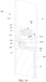
- FIG. 7 The design of an air path for pressure sensing of the sensor 50 is shown in FIG. 7 , FIG. 9 to FIG. 12 , and FIG. 14 .
- a first air hole 327 penetrating through the second portion 32, and a first channel portion 2542 and a second channel portion 2515 that are defined by the support 250 performs airflow communication between the first sensing surface 510 of the sensor 50 and the receiving cavity 27, to sense the pressure of the airflow during the inhalation of the user, for example, as shown by arrow R3 in FIG. 4 .
- arrow R3 the design of an air path for pressure sensing of the sensor 50
- a cross-sectional area of the first channel portion 2542 is larger than a cross-sectional area of the second channel portion 2515.
- the first channel portion 2542 is perpendicular to the second channel portion 2515.
- the first channel portion 2542 is located between the battery cell 21 and the first support part 251.
- the electronic atomization device includes an air channel.
- the air channel includes a first channel portion 2542 and a second channel portion 2515.
- a seal element 29, to provide sealing between the second portion 32 and the first channel portion 2542/wall 2543 of the support 250.
- the seal element 29 is made of a soft material such as silicone.
- the seal element 29 includes: a base portion 291 basically extending flatly and straightly, and an extension portion 292 extending out of one side of the base portion 291.
- the base portion 291 is basically a sheet or the like.
- the base portion 291 has a first surface 2910 and a second surface 2920 that face away from each other.
- the extension portion 292 extends in a manner that the second surface 2920 faces away from the first surface 2910.
- extension portion 292 protrudes out of the base portion 291.
- the base portion 291 is provided with a second air hole 293 which penetrates from the first surface 2910 to the second surface 2920.
- the first surface 2910 of the base portion 291 abuts against or is bonded to the wall 2543 for defining the first channel portion 2542.
- the second surface 2920 abuts against or is bonded to the second portion 32.
- the base portion 291 provides airtight sealing between the second portion 32 and the wall 2543.
- the second air hole 293 is aligned with the first air hole 327 in the second portion 32.
- the second air hole 293 and the first air hole 327 together provide a communication path between the first sensing surface 510 of the sensor 50 and the first channel portion 2542.
- the extension portion 292 at least partially extends into the first channel portion 2542 defined by the wall 2543, which is advantageous for assembling and positioning.
- the extension portion 292 is substantially U-shaped or has a U-shaped cross section.
- An opening 2922 is formed in one side of the extension portion 292 facing away from the base portion 291, and an opening 2921 is also formed in one side of the extension portion 292 close to the first support part 251 of the support 250.
- the extension portion 292 is arranged around a portion of the second air hole 293.
- the base portion 291 is at least partially pressed or compressed between the second portion 32 and the wall 2543, which is advantageous for improving the airtightness.
- At least one first convex rib 2911 having a closed ring shape is arranged on the first surface 2910 of the base portion 291, and the first convex rib 2911 surrounds the extension portion 292 and/or the second air hole 293 and/or the first channel portion 2542.
- At least one second convex rib 2912 having a closed ring shape is arranged on the second surface 2920 of the base portion 291, and the second convex rib 2912 surrounds the second air hole 293 and/or the first air hole 327.
- the second air hole 293 deviates from the center of the base portion 291. For example, as shown in FIG. 11 and FIG. 12 , the second air hole 293 is closer to the opening 2921.
- the second convex rib 2912 abuts against a surface of the second portion 32.
- the first convex rib 2911 abuts against the wall 2543 of the first channel portion 2542.
- An interference fit region of the base portion 291 of the seal element 29 formed by the first convex rib 2911 and the second convex rib 2912 is advantageous for improving the airtightness.
- the second sensing surface 520 of the sensor 50 is exposed. Specifically, the second sensing surface 520 is exposed in the spacing space 254, and then is communicated with an external environmental atmosphere through a gap or an assembling gap in the power supply mechanism 200.
- FIG. 15 to FIG. 17 are schematic diagrams of a power supply mechanism 200 according to another embodiment.
- a second portion 32a extending from a first portion 31a is parallel to a width direction and a thickness direction of the power supply mechanism 200 and perpendicular to a length direction of the power supply mechanism 200.
- the second portion 32a has an upper side and a lower side that face away from each other in the thickness direction.
- a first sensing surface 510a of a sensor 50a is arranged on or combined with a lower side surface of the second portion 32a.
- an upper side surface of the second portion 32a is arranged or provided with a contact assembly, including: an electrical contact 23a, and a contact holder 22a moulded around the electrical contact 23a by a mouldable material such as plastic.
- the electrical contact 23a is integrated with the contact holder 22a, and the contact holder 22a directly surrounds and maintains the electrical contact 23a.
- the electrical contact 23a penetrates through the contact holder 22a in the length direction of the power supply mechanism 200.
- the electrical contact 23a is partially exposed out of an upper side surface of the contact holder 22a, and the electrical contact 23a further partially passes through to a lower side surface of the contact holder 22a.
- the portion of the electrical contact 23a passing through to the lower side surface of the contact holder 22a further penetrates from an upper side of the second portion 32a to a lower side of the second portion 32a, and is soldered on the lower side surface of the second portion 32a through a soldering material such as soldering tin, thereby forming an electrical connection to the second portion 32a.
- a first support part 251a of the support 250a defines a side opening 2513a facing or close to the front side 2150.
- the contact holder 22a is accommodated and maintained in the side opening 2513a, so that the contact holder 22a is combined with or fastened to the first support part 251a of the support 250a.
- the contact holder 22a is provided with one or more clamping projections 221a surrounding the contact holder 22a.
- a clamping slot 2516a is provided in an inner wall of the side opening 2513a of the first support part 251a of the support 250a, so that the clamping projections 221a of the contact holder 22a extend into the clamping slot 2516a, to securely connect or maintain the contact holder 22a in the side opening 2513a.
- the second portion 32a is located in the spacing space 254a, and abuts against the lower side surface of the first support part 251a facing the second support part 252a.
- the seal element 26a includes: an end wall 2610a, and an annular peripheral side wall 2620a extending from the end wall 2610a.
- the peripheral side wall 2620a surrounds and encloses the first support part 251a in a circumferential direction, to provide sealing between the support 250a and the shell 210.
- the end wall 2610a abuts against and covers a surface of the first support part 251a adjacent to the receiving cavity 27.
- the end wall 2610a of the seal element 26a is further defined with:
- the end wall 2610a of the seal element 26a is further defined with: a groove 2611a, where the avoidance hole 261a is located in the groove 2611a.
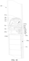
- the sensor 50a On an airflow path sensed by the sensor 50a, as shown in FIG. 15 to FIG. 18 , the sensor 50a is arranged on the lower side surface of the second portion 32a.
- the sensor 50a is generally a cube, and the sensor 50a has a first sensing surface 510a and a second sensing surface 520a that face away from each other.
- the first sensing surface 510a abuts against or is bonded to the lower side surface of the second portion 32a.
- the sensor 50a deviates from a central axis of the power supply mechanism 200. Specifically, the sensor 50a is close to the rear side 2160.
- the second portion 32a is provided with a first air hole 327a penetrating through the second portion 32a.
- the first sensing surface 510a is opposite to the first air hole 327a.
- a contact assembly combined with an upper surface of the second portion 32a is arranged to avoid the first air hole 327a.
- the electrical contact 23a and the contact holder 22a are arranged to avoid the first air hole 327a.
- the channel 2515a is arranged on the first support part 251a of the support 250, and is communicated with the receiving cavity 27.
- the channel 2515a extends in the length direction of the power supply mechanism 200. In the length direction of the power supply mechanism 200, the channel 2515a is aligned with the first air hole 327a.
- the channel 2515a is spaced apart from the first air hole 327a, and there is a space between them.
- the channel 2515a is isolated from the side opening 2513a. Alternatively, the channel 2515a and the side opening 2513a are spaced apart.
- a seal element 29a is arranged between the channel 2515a of the first support part 251a and the first air hole 327a of the second portion 32a.
- the seal element 29a is configured to: provide a path of airflow communication between the channel 2515a and the first air hole 327a, and provide airtight sealing.
- the seal element 29a is approximately square, and abuts against and is combined between the upper side surface of the second portion 32a and the channel 2515a.
- the contact holder 22a is provided with an accommodating cavity 222a facing the rear side 2160, and the seal element 29a at least partially extends into the accommodating cavity 222a for maintenance.
- the seal element 29a is roughly constructed into a block.
- the seal element 29a includes a portion 291a and a portion 292a that are arranged in sequence in the length direction.
- an extension length of the portion 291a is greater than an extension length of the portion 292a
- a thickness of the portion 291a is greater than a thickness of the portion 292a.
- a width of the portion 291a is less than a width of the portion 292a.
- a second air hole 293a that penetrates through the portion 291a in the thickness direction is provided in the portion 291a.
- the portion 291a partially extends into the accommodating cavity 222a, so as to fix the seal element 29a.
- the second air hole 293a is aligned with the channel 2515a and/or the first air hole 327a, thereby communicating the channel 2515a with the first air hole 327a.
- the portion 292a extends out of and abuts against an edge of the second portion 32a, to achieve a stop function, so as to prevent the portion 291a from moving.
- the portion 291a includes a side first surface 2910a and a side second surface 2920a that face away from each other in the thickness direction. After assembling, the side first surface 2910a abuts against the first support part 251a, and the side second surface 2920a abuts against and is bonded to the upper side surface of the second portion 32a.
- At least one closed annular first convex rib 2911a surrounding the second air hole 293a and/or the channel 2515a is arranged on the side first surface 2910a.
- At least one closed annular second convex rib 2912a surrounding the second air hole 293a and/or the first air hole 327a is arranged on the side first surface 2910a. Then, after assembling, the first convex rib 2911a and the second convex rib 2912a are pressed and compressed, to define interference fit between the portion 291a of the seal element 29a and the second portion 32a and/or the first support part 251a, which is advantageous for airtightness.
- the seal element 70a at least partially covers and surrounds or encloses the sensor 50a, to improve the sensing sensitivity and accuracy of the second sensing surface 520a.
- the seal element 70a has a plurality of grooves adjacent to the lower side surface of the second portion 32a, such as a groove 72a, a groove 73a, and a groove 74a.
- the sensor 50a After assembling, the sensor 50a at least partially extends into or is accommodated in the groove 72a, to avoid that the second sensing surface 520a of the sensor 50a is bonded or sealed by the seal element 70a.
- the second sensing surface 520a of the sensor 50a is spaced from an inner bottom wall of the groove 72a of the seal element 70a.
- circuit board assembly 30a further includes:
- the first circuit board and/or the second circuit board and/or the third circuit board may be hard PCBs or soft PCBs. In some implementations, the first circuit board and/or the second circuit board and/or the third circuit board may be independently prepared or obtained and then connected through flat flexible cables. Alternatively, in some other implementations, the first circuit board and/or the second circuit board and/or the third circuit board are/is formed by bending different portions of another foldable or bendable circuit board.
Landscapes
- Engineering & Computer Science (AREA)
- Microelectronics & Electronic Packaging (AREA)
- Secondary Cells (AREA)
- Charge And Discharge Circuits For Batteries Or The Like (AREA)
Abstract
Description
- This application claims priority to
Chinese Patent Application No. 202211262392.X, filed with the China National Intellectual Property Administration on October 14, 2022 - Embodiments of the present application relate to the field of electronic atomization technologies, and in particular, to an electronic atomization device, a power supply mechanism for the electronic atomization device, and a circuit board for the electronic atomization device.
- Tobacco products (such as cigarettes, cigars, and the like) burn tobacco during use to produce tobacco smoke. Attempts are made to replace these tobacco-burning products by making products that release compounds without burning.
- An example of such products is a heating device, which releases compounds by heating rather than burning materials. For example, the material may be tobacco or other non-tobacco products. These non-tobacco products may or may not include nicotine. In another example, aerosol-providing articles are provided, for example, a so-called electronic atomization device. These electronic atomization devices usually include a liquid aerosol-forming matrix. The liquid aerosol-forming matrix is heated to be atomized, thus forming an inhalable aerosol.
- An embodiment of the present application provides an electronic atomization device, including a first side and a second side which face away from each other in a width direction, and:
- a heating element, configured to heat an aerosol-forming matrix to form an aerosol;
- a battery cell, configured to supply power; and
- a charging assembly, configured to charge the battery cell; and
- a circuit board assembly, at least including:
- a first portion, located between the battery cell and the second side in the width direction of the electronic atomization device, where a controller is arranged on the first portion, and the controller is configured to control the battery cell to supply electric power to the heating element;
- a second portion, extending from the first portion toward the first side, where the second portion is configured to be electrically connected to the heating element, to output the electric power of the battery cell to the heating element; and
- a third portion, extending from the first portion toward the first side, where the third portion is connected to the charging assembly.
- In some other implementations, the electronic atomization device includes a near end and a far end which face away from each other in a length direction, where the third portion is closer to the far end than the second portion.
- In some other implementations, the second portion and/or the third portion are substantially perpendicular to the first portion.
- In some other implementations, the second portion and the third portion are perpendicular to each other;
alternatively, the second portion and the third portion are parallel to each other. - In some other implementations, any two of the first portion, the second portion, and the third portion are perpendicular to each other.
- In some other implementations, the first portion is arranged perpendicular to the width direction of the electronic atomization device.
- In some other implementations, the second portion and the third portion are arranged on a same side of the first portion in a thickness direction of the electronic atomization device.
- In some other implementations, a length dimension of the first portion extending in the length direction of the electronic atomization device is greater than a width dimension of the second portion extending in the width direction of the electronic atomization device.
- In some other implementations, the length dimension of the first portion is between 40 mm and 60 mm;
- and/or a width dimension of the second portion is between 10 mm and 18 mm;
- and/or a width dimension of the third portion is between 6 mm and 12 mm.
- In some other implementations, the controller is arranged on a surface of the first portion that faces away from the battery cell.
- In some other implementations, the circuit board assembly further includes:
- a fourth portion, extending from the first portion toward the first side; a temperature sensor abutting against or adjacent to the battery cell is arranged on the fourth portion, to sense a temperature of the battery cell; and
- the controller is configured to prevent or reduce the electric power output by the battery cell when a temperature sensed by the temperature sensor is greater than a preset threshold.
- In some other implementations, the temperature sensor is combined with or arranged on a surface of the fourth portion that faces away from the battery cell.
- In some other implementations, the fourth portion is located between the second portion and the third portion in the length direction of the electronic atomization device.
- In some other implementations, a width dimension of the fourth portion extending in the width direction of the electronic atomization device is less than a width dimension of the second portion or the third portion extending in the width direction of the electronic atomization device.
- In some other implementations, the circuit board assembly further includes:
- a fourth portion, extending from the first portion toward the first side; a thermistor abutting against or adjacent to the battery cell is arranged on the fourth portion; and
- the controller is configured to prevent or reduce the battery cell from outputting electric power when an electrical characteristic of the thermistor exceeds a preset threshold.
- In some other implementations, the electrical characteristic includes a voltage value and/or a resistance value.
- In some other implementations, the electronic atomization device further includes:
- a plurality of light sources, configured to emit light,
- where the controller is configured to control, based on a change in a positive electrode voltage or an output voltage of the battery cell, the plurality of light sources to emit light in different quantities.
- In some other implementations, the controller is configured to:
- control, when the positive electrode voltage or the output voltage of the battery cell is greater than a first threshold, the plurality of light sources to emit light in a first quantity; and
- control, when the positive electrode voltage or the output voltage of the battery cell is less than the first threshold, the plurality of light sources to emit light in a second quantity; and the second quantity is less than the first quantity.
- In some other implementations, the electronic atomization device further includes:
one or more light sources, configured to emit light, where the one or more light sources are arranged on a surface of the first portion that faces the second side. - In some other implementations, the circuit board assembly includes:
at least one substrate layer, and a conductive line and/or an electronic device arranged on the substrate layer; and the first portion, the second portion, or the third portion includes a portion of the substrate layer. - In some other implementations, the substrate layer includes at least one of a polyimide layer, a polytetrafluoroethylene layer, a polycarbonate layer, a polyester layer, an aluminum foil layer, and a stainless steel layer.
- In some other implementations, hardness of the first portion is greater than hardness of the second portion and/or the third portion.
- In some other implementations, the first portion at least includes:
- a soft first substrate layer; and
- a hard second substrate layer.
- In some other implementations, the first portion includes a stainless steel layer.
- In some other implementations, the second portion and/or the third portion includes an organic polymer layer.
- In some other implementations, the first portion, the second portion, and the third portion are formed by bending a sheet base material.
- In some other implementations, the second portion is in non-contact with the battery cell;
and/or the third portion at least partially abuts against or is at least partially combined with a surface of the battery cell. - In some other implementations, the second portion is located between the battery cell and the near end.
- In some other implementations, the electronic atomization device further includes:
an electrical contact, electrically connected between the second portion and the heating element, where during use, the second portion is in conductive connection to the heating element through the electrical contact, to output the electric power of the battery cell to the heating element. - In some other implementations, the second portion is provided with:
a contact connection portion, identified by a color or a pattern; and the electrical contact is electrically connected to the contact connection portion to form electrical conduction with the second portion. - In some other implementations, the contact connection portion is identified and defined by a circle pattern that is formed on the second portion and has an identifiable color.
- In some other implementations, the electronic atomization device further includes:
- a sensor, arranged or combined on the second portion, to sense an airflow flowing through the electronic atomization device during inhalation of a user;
- the contact connection portion includes a first contact connection portion and a second contact connection portion that are spaced apart; and the sensor is located between the first contact connection portion and the second contact connection portion.
- In some other implementations, the electronic atomization device further includes:
- a support, a first support part and a second support part that are arranged in the length direction of the electronic atomization device, where the first support part is closer to the near end than the second support part;
- the electrical contact is at least partially maintained at the first support part; and
- the battery cell is at least partially maintained at the second support part.
- In some other implementations, the first support part is moulded by a mouldable material and at least partially surrounds the electrical contact.
- In some other implementations, the second portion is at least partially accommodated between the first support part and the second support part.
- In some other implementations, the electronic atomization device further includes:
- a sensor, arranged or combined on the second portion, to sense a change in an airflow flowing through the electronic atomization device during inhalation of a user; and
- the controller is configured to control, based on a sensing result of the sensor, the battery cell to supply the electric power to the heating element.
- In some other implementations, the electronic atomization device further includes:
- a sensor, arranged or combined on the second portion, to sense a pressure difference between a pressure, caused by an airflow flowing through the electronic atomization device during inhalation of a user, and an environmental atmospheric pressure,
- where the controller is configured to control, based on the pressure difference, the battery cell to supply the electric power to the heating element.
- In some other implementations, the controller is configured to control, when the pressure difference is greater than a preset threshold, the battery cell to supply the electric power to the heating element.
- In some other implementations, the controller is configured to control the battery cell to supply the electric power to the heating element proportionally or linearly according to the pressure difference.
- In some other implementations, a volume of the sensor is less than 12 mm3.
- In some other implementations, the sensor has a length of 2 to 3.5 mm, a width of 1.5 to 2.5 mm, and a thickness of 0.6 to 1.4 mm.
- In some other implementations, the sensor is a micro electro mechanical system (MEMS)-based sensor.
- In some other implementations, the sensor is arranged in a manner of deviating from a central axis of the electronic atomization device.
- In some other implementations, the sensor is basically square; and
the sensor is perpendicular to the length direction of the electronic atomization device, or the sensor is parallel to the length direction of the electronic atomization device. - In some other implementations, the sensor includes:
- a first sensing surface, configured to sense the pressure caused by the airflow flowing through the electronic atomization device during the inhalation of the user; and a second sensing surface, configured to sense the environmental atmospheric pressure, where
- the first sensing surface is combined with or abuts against the second portion; and
- the second sensing surface is at least partially exposed inside the electronic atomization device.
- In some other implementations, the second portion includes a soft substrate layer made of an organic polymer material; and
the first sensing surface is at least partially combined with the substrate layer, so that at least a portion of the substrate layer provides airtight sealing between the second portion and the first sensing surface. - In some other implementations, the electronic atomization device further includes:
- a support, configured to accommodate or maintain the battery cell; and
- an air channel, at least partially defined on the support, to provide a channel for communicating the first sensing surface to the airflow flowing through the electronic atomization device during the inhalation.
- In some other implementations, the electronic atomization device further includes:
a flexible seal element, at least partially located between the second portion and the support and surrounding the air channel, to provide sealing between the second portion and the air channel. - In some other implementations, the electronic atomization device further includes:
a first air hole, penetrating through two opposite sides of the second portion, to provide a channel for communicating the first sensing surface to the airflow of the air channel, where the first sensing surface covers the first air hole. - In some other implementations, the air channel includes: a first channel portion close to the first sensing surface and a second channel portion facing away from the first sensing surface; and
an angle is formed between the first channel portion and the second channel portion, or the first channel portion and the second channel portion are vertically arranged. - In some other implementations, the air channel includes: a first channel portion close to the first sensing surface and a second channel portion facing away from the first sensing surface; and a cross-sectional area of the first channel portion is smaller than a cross-sectional area of the second channel portion.
- In some other implementations, the seal element at least includes:
- a first surface, abutting against or combined with the second portion;
- a second surface, abutting against or combined with the support; and
- a second air hole, extending from the first surface to the second surface, to provide a channel for communicating the first sensing surface with the airflow of the air channel.
- In some other implementations, the seal element further includes:
- a first convex rib, located on the first surface, where the first convex rib defines at least one closed ring surrounding the second air hole;
- and/or a second convex rib, located on the second surface, where the second convex rib defines at least one closed ring surrounding the second air hole and/or the air channel.
- In some other implementations, the second air hole deviates from a center of the seal element.
- In some other implementations, the seal element at least partially extends into the air channel.
- In some other implementations, the seal element includes:
- a base portion, at least partially located between the second portion and the support and surrounding the air channel, to provide sealing between the second portion and the air channel; and
- an extension portion, extending away from the base portion and at least partially extending into the air channel.
- In some other implementations, the electronic atomization device includes:
- a retaining wall, extending in the length direction of the electronic atomization device and arranged substantially perpendicular to the width direction of the electronic atomization device,
- where the battery cell is at least partially accommodated between the retaining wall and the first side and abuts against the retaining wall; and
- the first portion is at least partially accommodated between the retaining wall and the second side and abuts against the retaining wall.
- In some other implementations, a distance between the retaining wall and the first side is greater than a distance between the retaining wall and the second side.
- In some other implementations, a distance between the retaining wall and the first side is between 10 mm and 20 mm;
and/or a distance between the retaining wall and the second side is between 5 mm and 10 mm. - In some other implementations, the electronic atomization device further includes:
a fastening component, at least partially accommodated between the first portion and the second side, to securely press the first portion against the retaining wall. - In some other implementations, at least one convex post extending toward the second side is arranged on the retaining wall; and
a hole through which the convex post passes is provided in the first portion. - In some other implementations, the first portion and the second portion are connected through a flat flexible cable;
and/or the first portion is connected to the third portion through a flat flexible cable. - In some other implementations, the charging assembly includes:
- a charging circuit board and a charging interface combined with the charging circuit board;
- a surface of the charging circuit board facing away from the charging interface is provided with:
- a battery cell connection portion, where a positive electrode and negative electrode of the battery cell are connected to the battery cell connection portion; and
- a circuit connection portion, where the third portion is connected to the circuit connection portion.
- In some other implementations, the battery cell connection portion and the circuit connection portion have different shapes and/or colors.
- Another embodiment of the present application further provides an electronic atomization device, including a first side and a second side which face away from each other in a width direction, and:
- a heating element, configured to heat an aerosol-forming matrix to form an aerosol;
- a battery cell, configured to supply power;
- a charging assembly, configured to charge the battery cell; and
- a circuit board assembly, at least including:
- a first portion, located between the battery cell and the second side in the width direction of the electronic atomization device, where a controller is arranged on the first portion, and the controller is configured to control the battery cell to supply electric power to the heating element;
- a second portion, extending from the first portion toward the first side, where a sensor is arranged on the second portion, to sense an airflow flowing through the electronic atomization device during inhalation of a user; and
- a third portion, extending from the first portion toward the first side, where the third portion is connected to the charging assembly.
- Another embodiment of the present application further provides an electronic atomization device, including a first side and a second side which face away from each other in a width direction, and:
- a heating element, configured to heat an aerosol-forming matrix to form an aerosol;
- a battery cell, configured to supply power;
- a charging assembly, configured to charge the battery cell; and
- a circuit board assembly, at least including:
- a first portion, located between the battery cell and the second side in the width direction of the electronic atomization device, where a controller is arranged on the first portion and at least configured to control the battery cell to supply electric power to the heating element;
- a second portion, extending from the first portion toward the first side, to output the electric power of the battery cell to the heating element,
- a third portion, extending from the first portion toward the first side, where the third portion is connected to the charging assembly; and
- any two of the first portion, the second portion, and the third portion are perpendicular to each other.
- Another embodiment of the present application further provides an electronic atomization device, including a first side and a second side which face away from each other in a width direction, and:
- a heating element, configured to heat an aerosol-forming matrix to form an aerosol;
- a battery cell, configured to supply power;
- a circuit board assembly, at least including:
- a first portion, located between the battery cell and the second side in the width direction of the electronic atomization device, where a controller is arranged on the first portion and at least configured to control the battery cell to supply electric power to the heating element;
- a second portion, extending from the first portion toward the first side, to output the electric power of the battery cell to the heating element,
- where the first portion includes a stainless steel layer and a flexible organic polymer layer combined with the stainless steel layer.
- Another embodiment of the present application further provides an electronic atomization device, including a first side and a second side which face away from each other in a width direction, and:
- a heating element, configured to heat an aerosol-forming matrix to form an aerosol;
- a battery cell, configured to supply power;
- a first circuit board, located between the battery cell and the second side in the width direction of the electronic atomization device, where a first circuit board is configured to control the battery cell to supply electric power to the heating element; and
- a second circuit board, located between the heating element and the battery cell in a length direction of the electronic atomization device, where a sensor is arranged on the second circuit board, to sense an airflow flowing through the electronic atomization device during inhalation of a user; and
- the first circuit board and the second circuit board are connected through a flat flexible cable.
- Another embodiment of the present application further provides an electronic atomization device, including a first side and a second side which face away from each other in a width direction, and:
- a heating element, configured to heat an aerosol-forming matrix to form an aerosol;
- a battery cell, configured to supply power;
- a circuit board assembly, at least including:
- a first portion, located between the battery cell and the second side in the width direction of the electronic atomization device, where a controller is arranged on the first portion and at least configured to control the battery cell to supply electric power to the heating element;
- a second portion, extending from the first portion toward the first side, where a sensor is arranged on the second portion, to sense an airflow flowing through the electronic atomization device during inhalation of a user; and
- a retaining wall, extending in the length direction of the electronic atomization device and arranged substantially perpendicular to the width direction of the electronic atomization device,
- where the battery cell is at least partially accommodated or maintained between the retaining wall and the first side and abuts against the retaining wall; and
- the first portion is at least partially accommodated or maintained between the retaining wall and the second side and abuts against the retaining wall.
- Still another embodiment of the present application further provides power supply mechanism for an electronic atomization device, configured to supply power to the electronic atomization device, and including a first side and a second side which face away from each other in a width direction, and:
- a receiving cavity, configured to receive at least a portion of the atomizer;
- a battery cell, configured to supply power;
- a charging assembly, configured to charge the battery cell; and
- a circuit board assembly, at least including:
- a first portion, located between the battery cell and the second side in the width direction of the power supply mechanism, where a controller being arranged on the first portion and at least configured to control the battery cell to supply electric power to the atomizer;
- a second portion, extending from the first portion toward the first side, where the second portion being configured to output the electric power of the battery cell to the atomizer; and
- a third portion, extending from the first portion toward the first side in the width direction of the power supply mechanism, where the third portion is connected to the charging assembly.
- Yet another embodiment of the present application further provides a circuit board for the electronic atomization device, having a first end and a second end that deviate from each other in a length direction, and a first side and a second side that extend between the first end and the second end and deviate from each other, where the circuit board includes:
- a first portion, extending between the first end and the second end, where a controller is arranged on the first portion;
- a second portion, extending from the first portion toward the first side and being close to the first end, where a sensor for sensing an airflow is arranged on the second portion; and
- a third portion, extending from the first portion toward the first side and being close to the second end, where the third portion is configured to be connected to a charging assembly that charges the electronic atomization device.
- According to the foregoing electronic atomization device, the circuit board assembly is divided into a plurality of portions, which is advantageous for preparation and assembling.
- One or more embodiments are exemplarily described with reference to the corresponding figures in the accompanying drawings, and the descriptions are not to be construed as limiting the embodiments. Elements in the accompanying drawings that have same reference numerals are represented as similar elements, and unless otherwise particularly stated, the figures in the accompanying drawings are not drawn to scale.
-
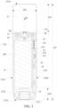
FIG. 1 is a schematic diagram of an electronic atomization device according to an embodiment; -
FIG. 2 is a schematic structural diagram of a power supply mechanism inFIG. 1 according to an embodiment; -
FIG. 3 is a schematic cross-sectional view of a power supply mechanism inFIG. 1 in one angle; -
FIG. 4 is a schematic exploded diagram of the power supply mechanism inFIG. 3 in one angle; -
FIG. 5 is a schematic exploded diagram of some components of the power supply mechanism inFIG. 4 in another angle; -
FIG. 6 is a schematic exploded diagram of some components of the power supply mechanism inFIG. 4 in another angle; -
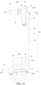
FIG. 7 is a schematic diagram of some components of the power supply mechanism inFIG. 4 after assembling, in one angle; -
FIG. 8 is a schematic diagram of some components of the power supply mechanism inFIG. 4 after assembling in another angle; -
FIG. 9 is a schematic diagram of a support inFIG. 4 from another perspective. -
FIG. 10 is a schematic diagram of a circuit board assembly inFIG. 4 in another angle; -
FIG. 11 is a schematic diagram of a seal element inFIG. 6 in one angle; -
FIG. 12 is a schematic diagram of a seal element inFIG. 6 in another angle; -
FIG. 13 is a schematic cross-sectional diagram of a portion of a circuit component; -
FIG. 14 is a schematic cross-sectional view of a power supply mechanism inFIG. 1 in another angle; -
FIG. 15 is a schematic exploded view of some components of a power supply mechanism device according to another embodiment in one angle; -
FIG. 16 is a schematic exploded diagram of some components of the power supply mechanism inFIG. 15 in another angle; -
FIG. 17 is a schematic exploded diagram of some components of the power supply mechanism inFIG. 15 in another angle; -
FIG. 18 is a schematic exploded diagram of the power supply mechanism inFIG. 15 in another angle; -
FIG. 19 is a schematic diagram of a seal element inFIG. 17 in another angle; -
FIG. 20 is a schematic diagram of a seal element inFIG. 19 in another angle; and -
FIG. 21 is a schematic diagram of a seal element inFIG. 16 in another angle. - For ease of understanding of the present application, the present application is described below in more detail with reference to accompanying drawings and specific implementations.
- An embodiment of the present application provides an electronic atomization device, configured to heat a liquid aerosol-forming matrix to form an aerosol for inhalation. Alternatively, in some other embodiments, the aerosol-forming matrix may be a solid or a colloid.
- An embodiment of the present application provides an electronic atomization device. Referring to
FIG. 1 , the electronic atomization device includes anatomizer 100 for storing a liquid aerosol-forming matrix and atomizing the liquid aerosol-forming matrix to form an aerosol, and apower supply mechanism 200 for supplying power to theatomizer 100. - In an optional implementation, for example, as shown in
FIG. 1 , theatomizer 100 includes: - a
liquid storage cavity 12 configured to store a liquid aerosol-forming matrix; - a
heating element 13 configured to heat and atomize the liquid aerosol-forming matrix to form an aerosol; - and an
electrical contact 11 electrically connected to theheating element 13, to guide a current on theheating element 13 during use. - In an optional implementation, for example, as shown in
FIG. 1 , thepower supply mechanism 200 includes: a receivingcavity 27 arranged at one end in a length direction and configured to receive and accommodate at least a portion of theatomizer 100; and anelectrical contact 23 at least partially exposed out of a surface of the receivingcavity 27 and configured to supply power to theatomizer 100 when at least a portion of theatomizer 100 is received and accommodated in thepower supply mechanism 200. - According to the implementation shown in
FIG. 1 , theelectrical contact 11 is arranged at an end portion of theatomizer 100 opposite to thepower supply mechanism 200 in the length direction, so that when at least a portion of theatomizer 100 is received in the receivingcavity 27, theelectrical contact 11 is in contact with and abuts against theelectrical contact 23 to conduct electricity. - A
seal element 26 is arranged in thepower supply mechanism 200, and at least a portion of an internal space of thepower supply mechanism 200 is separated through theseal element 26 to form the above receivingcavity 27. In the implementation shown inFIG. 1 , theseal element 26 is configured to extend in a cross section direction of thepower supply mechanism 200, and is optionally prepared by using a flexible material such as silica gel, so as to prevent the liquid aerosol-forming matrix seeping from theatomizer 100 to the receivingcavity 27 from flowing into thepower supply mechanism 200. - In the implementation shown in
FIG. 1 , thepower supply mechanism 200 further includes abattery cell 21 for supplying power; and acircuit board assembly 30, which operably guides a current between thebattery cell 21 and theelectrical contact 23. - During use, the
power supply mechanism 200 includes asensor 50, configured to sense an inhalation airflow generated by theatomizer 100 during inhalation, so that thecircuit board assembly 30 controls thebattery cell 21, based on a detection signal of thesensor 50, to supply power to theatomizer 100. - Further, in the implementation shown in
FIG. 1 , a charginginterface 24 is arranged on the other end of thepower supply mechanism 200 facing away from the receivingcavity 27, and is configured to supply power to thebattery cell 21. The charginginterface 24 is a USB Type-C interface. Alternatively, in some other changed embodiments, the charginginterface 24 may further use a USB 2.0 interface, a USB 3.0 interface, or a USB 4-pin interface. - The embodiments in
FIG. 2 to FIG. 3 show schematic structural diagrams of thepower supply mechanism 200 inFIG. 1 according to an embodiment, including:
ashell 210 which is lengthwise cylindrical. In addition, during implementation, a length of theshell 210 is greater than a width, and the width is greater than a thickness, so that theshell 210 is constructed into a flat shape. - In addition, in some implementations, a length dimension d11 of the
shell 210 is between 70 mm and 100 mm. In addition, a width dimension d21 of theshell 210 is between 15 mm and 25 mm. Moreover, a thickness dimension d31 of theshell 210 is between 8 mm and 15 mm. - In some examples, the
shell 210 may be formed by a metal or alloy such as stainless steel or aluminum. Other suitable materials including various types of plastic (e.g. polycarbonate), metal-plating over plastic, ceramic, and the like may alternatively be used. - The
shell 210 includes anear end 2110 and afar end 2120 that face away from each other in the length direction. During use, thenear end 2110 is an end portion for accommodating and receiving theatomizer 100, and thefar end 2120 is an end portion for being connected to an external charging device, to charge thepower supply mechanism 200. - The
shell 210 has afront side 2150 and arear side 2160 that face away from each other in a thickness direction. Theshell 210 has asurface 2111 at thenear end 2110, and thesurface 2111 is inclined. Specifically, as shown by arrow R1 inFIG. 2 , thesurface 2111 is obliquely arranged from thefront side 2150 to therear side 2160 in the thickness direction. Specifically, a distance d11 between thefront side 2150 of thesurface 2111 and thefar end 2120 is the length dimension d11 of theshell 210. In addition, a distance d12 between therear side 2160 of thesurface 2111 and thefar end 2120 is less than the length dimension d11 of theshell 210. A distance d12 between therear side 2160 of thesurface 2111 and thefar end 2120 is between 75 mm and 95 mm. - The receiving
cavity 27 of thepower supply mechanism 200 is opened at thenear end 2110, to receive theatomizer 100. In addition, an extension dimension d13 of the receivingcavity 27 in the length direction of thepower supply mechanism 200 is between 20 mm to 30 mm. - The
shell 210 has anopening 2122 located at thefar end 2120, to expose the charginginterface 24. In addition, theshell 210 has asection 2122 close to or located at thefar end 2120. A width dimension and/or a thickness dimension of thesection 2122 gradually decreases in a direction close to thefar end 2120, so that a portion of theshell 210 close to thefar end 2120 has a gradually contracted or gathered shape. In addition, in some embodiments, an extension length d14 of thesection 2122 is between 8 mm to 20 mm. - In addition, further, as shown in
FIG. 2 andFIG. 3 , theshell 210 further includes:
afirst side 2130 and asecond side 2140 that face away from each other in a width direction. - Further, as shown in
FIG. 2 andFIG. 3 , theshell 210 is provided with:
anair inlet 213, configured to allow, when a user puffs on theatomizer 100, external air to enter the receivingcavity 27 and further enter theatomizer 100, as shown by arrow R2 inFIG. 2 andFIG. 3 . Theair inlet 213 is located on or arranged on thefirst side 2130 and/or thesecond side 2140. In addition, in the embodiment shown inFIG. 3 , in the width direction of thepower supply mechanism 200, theair inlet 213 is substantially flush with an end portion of the receivingcavity 27 that faces away from thenear end 2110. - Further, as shown in
FIG. 2 andFIG. 3 , theshell 210 is provided with:
aninput element 211 operated by a user to form an input signal. Then, thepower supply mechanism 200 selectively switches between a locked state and an unlocked state according to the input signal of the user. For example, in the locked state, thepower supply mechanism 200 is prevented from outputting power to theatomizer 100, and in the unlocked state, thepower supply mechanism 200 is allowed to output power to theatomizer 100. - In some other implementations, the
input element 211 is selected from a mechanical button, a film button, a mechanical switch, a rotary encoder, a dial, a knob, a capacitive touch button, a resistive touch button, an operating lever, a slider, a trigger button, a touch screen, and a magnetic switch. In the implementations shown inFIG. 2 andFIG. 3 , theinput element 211 is, for example, a mechanical button. Thepower supply mechanism 200 controls, according to an input signal of theinput element 211, for example, a pressing action or event performed by a user using the mechanical button, to lock or unlock thepower supply mechanism 200. - Further, as shown in
FIG. 2 andFIG. 3 , theshell 210 is provided with:
alight source hole 212, configured to allow light emitted by alight source 41 to pass through theshell 210 through thelight source hole 212, so as to be received by a user. In some implementations, a user may observe a light-emitting state of thelight source 41 through thelight source hole 212, to determine a current battery level of thepower supply mechanism 200. - In some embodiments, a plurality of
light sources 41 are provided. One or more of thelight sources 41 may be turned on to emit light, to prompt a user of different battery levels of thepower supply mechanism 200. For example, in a specific embodiment, fourlight sources 41 are provided, which are arranged in sequence in the length direction. During implementation, the fourlight sources 41 may be made to emit light simultaneously, so as to inform a user that a current battery level is full or is relatively sufficient. In addition, only one of thelight sources 41 is made to emit light, to inform the user that a current battery level is low, so as to prompt the user of charging. In addition, only two or three of thelight sources 41 may be made to emit light simultaneously, to prompt the user of a current battery level. For example, when three of thelight sources 41 emit light simultaneously, it indicates that a current battery level is less than a battery level when the four light sources emit light simultaneously and greater than a battery level when two of thelight sources 41 emit light simultaneously. For another example, when two of thelight sources 41 emit light simultaneously, it indicates that a current battery level is less than a battery level when three light sources emit light simultaneously and greater than a battery level when only one light source emits light. - In some embodiments, the
light sources 41 include light-emitting diodes (LEDs). - In addition, in some embodiments, the
input element 211 and thelight source hole 212 are both arranged on thesecond side 2140. In some embodiments, thelight source hole 212 is closer to thenear end 2110 than theinput element 211. In addition, theinput element 211 and thelight source hole 212 avoid the receivingcavity 27. Alternatively, theinput element 211 and thelight source hole 212 are closer to thefar end 2120 than the receivingcavity 27. - Further, as shown in
FIG. 3 to FIG. 8 , thepower supply mechanism 200 includes:
abattery cell 21, configured to supply power. In this implementation, thebattery cell 21 is a direct current battery cell. In an optional embodiment, a direct current supply voltage provided by thebattery cell 21 ranges from about 2.5 V to about 9.0 V, and a direct current provided by thebattery cell 21 ranges from about 2.5 A to about 20 A. For example, in a specific implementation, a direct current supply voltage provided by thebattery cell 21 ranges from 3.5V to about 5.0V. - Further, as shown in
FIG. 3 to FIG. 9 , thepower supply mechanism 200 includes:
asupport 250, configured to provide a support for the components in theshell 210. Thesupport 250 is configured to be a lengthwise shape extending inside theshell 210 in the length direction of thepower supply mechanism 200. Thesupport 250 is moulded by a mouldable material such as an organic polymer. The organic polymer is, for example, various types of plastic (e.g. polycarbonate and PEEK). - The
support 250 includes: afirst support part 251, asecond support part 252, and athird support part 253 which are arranged in sequence in the length direction. Thefirst support part 251 is close to thenear end 2110, and thethird support part 253 is close to thefar end 2120. One side of thesecond support part 252 facing or close to thefront side 2150 and one side of thethird support part 253 facing or close to thefront side 2150 are provided with openings or are opened. In addition, thefirst support part 251 is perpendicular to the length direction. - During implementation, the
first support part 251 is configured to support and maintain theelectrical contact 23. Thesecond support part 252 is configured to at least partially accommodate and maintain thebattery cell 21. Thethird support part 253 is configured to at least partially accommodate and maintain the charginginterface 24. In addition, during implementation, thefirst support part 251 is further configured to support and maintain theseal element 26. Specifically, theseal element 26 may surround or encircle an end surface or a peripheral side surface of thefirst support part 251 that faces thenear end 2110. For example, as shown inFIG. 5 , thefirst support part 251 is provided with agroove 2511 surrounding thefirst support part 251 in a circumferential direction. During assembling, theseal element 26 may be an annular silicon ring or the like. Thefirst support part 251 is enclosed and sleeved in thegroove 2511, to provide sealing between theshell 210 and thefirst support part 251. - During implementation, the
electrical contact 23 is a conductive elastic pin extending in the length direction of thepower supply mechanism 200. Theelectrical contact 23 is at least partially compressible. In addition, theelectrical contact 23 is maintained on thefirst support part 251, so as to be supported by thefirst support part 251. Alternatively, thesupport 250 is directly integrally moulded around theelectrical contact 23. In addition, during implementation, theelectrical contact 23 passes through thefirst support part 251 in the length direction of thepower supply mechanism 200. Theelectrical contact 23 passes through from one side of thefirst support part 251 facing or close to thenear end 2110 to the other side in the length direction of thepower supply mechanism 200. - In addition, during implementation, the
first support part 251 is provided with acontact hole 2512 that passes through from one side of thefirst support part 251 facing or close to thenear end 2110 to the other side, and theelectrical contact 23 is at least partially accommodated and maintained in thecontact hole 2512. Agroove 2514 is further arranged on one side of thefirst support part 251 facing thenear end 2110, to accommodate and maintain amagnetic element 28. - When the
atomizer 100 is at least partially received in the receivingcavity 27, themagnetic element 28 is in magnetic attraction with theatomizer 100, so that theatomizer 100 is stably received in the receivingcavity 27. In some embodiments, themagnetic element 28 is, for example, a magnetic body or a magnetic metal that is in magnetic attraction with a magnetic body. - In addition, during implementation, the
second support part 252 is opened toward or close to thefront side 2150, and thebattery cell 21 is at least partially accommodated and maintained in thesecond support part 252. In addition, during implementation, thethird support part 253 is opened toward or close to thefront side 2150, and the charginginterface 24 is at least partially accommodated and maintained in thesecond support part 253. - The
support 250 is further provided with apartition wall 2535 extending in a direction perpendicular to the length direction, and thesecond support part 252 and thethird support part 253 are separated and defined by thepartition wall 2535. Thepartition wall 2535 has an upper side surface facing thesecond support part 252 and a lower side surface facing thethird support part 253. After assembling, thebattery cell 21 abuts against the upper side surface of thepartition wall 2535. In addition, the charginginterface 24 abuts against the lower side surface of thepartition wall 2535. - In addition, the
support 250 is further provided with aspacing space 254 defined between thefirst support part 251 and thesecond support part 252. Thespacing space 254 is configured to partially accommodate and maintain a portion of thecircuit board assembly 30. Alternatively, thesensor 50 is mounted or arranged in thespacing space 254. - In addition, further as shown in
FIG. 3 to FIG. 9 , thepower supply mechanism 200 includes:
a chargingcircuit board 60 which is thin and sheet-like or plate-like. The chargingcircuit board 60 is, for example, a hard printed circuit board (PCB) or a soft PCB board. The charginginterface 24 is directly fixed or fastened on the chargingcircuit board 60 in a soldered manner or the like. - The charging
circuit board 60 is provided with:
a batterycell connection portion 64, which is, for example, a bonding pad or an electrical contact, and is configured to solder a positive electrode/a negative electrode of thebattery cell 21 for connection to conduct electricity. The batterycell connection portion 64 is connected to the charginginterface 24 through a conductive line printed or arranged on the chargingcircuit board 60, so that during use, the charginginterface 24 is connected to a positive electrode/negative electrode of thebattery cell 21 through the conductive line on the chargingcircuit board 60 to form electrical conduction, to charge thebattery cell 21. In addition, during implementation, the batterycell connection portion 64 is located on one side of the chargingcircuit board 60 facing away from the charginginterface 24. The batterycell connection portion 64 has a shape or a color different from that of another portion on a surface of the chargingcircuit board 60, which is advantageous for being identified and located by a device such as a color sensor or human eyes. For example, in some specific embodiments, the batterycell connection portion 64 is silver or a silver gray, and another portion on the surface of the chargingcircuit board 60 is green. - The charging
circuit board 60 is provided with: a charging integrated circuit (IC), for example, a common L4066 charging IC, a charging IC (SimTech), a CV1055P charging IC, an S083 charging IC prepared by using a single ASIC, and the like. The charging IC is configured to monitor and control charging on thebattery cell 21. - Further, after assembling, the charging
circuit board 60 is maintained at thethird support part 253 of thesupport 250. Moreover, after assembling, the charginginterface 24 is covered or blocked by the chargingcircuit board 60 at the opening of thethird support part 253. - In some other implementations, the charging
circuit board 60 is fastened to thethird support part 253 through a fastening component. For example, in specific implementations ofFIG. 4 to FIG. 8 , ascrew base 2531 and ascrew seat 2532 are arranged on thethird support part 253 of thesupport 250. The chargingcircuit board 60 is provided with ascrew hole 61 and ascrew hole 62. During assembling, ascrew 611 is connected to thescrew seat 2531 through thescrew hole 61, and ascrew 621 is connected to thescrew seat 2532 through thescrew hole 62, so as to fasten the chargingcircuit board 60 to thethird support part 253 of thesupport 250. - The charging
circuit board 60 is further provided with:
apositioning hole 63, arranged away from a center of the chargingcircuit board 60, to position the chargingcircuit board 60 during assembling. A positioningconvex post 2533 is arranged on thethird support part 253. During assembling, the positioningconvex post 2533 passes through thepositioning hole 63 of the chargingcircuit board 60 for positioning during assembling. In addition, during implementation, a plurality ofconvex teeth 2534 are further arranged on thethird support part 253, to allow the charginginterface 24 to abut against for being stopped when the charginginterface 24 is accommodated in thethird support part 253 by the opening. The plurality ofconvex teeth 2534 are parallel to each other or away from each other. - In addition, further, as shown in
FIG. 4 to FIG. 8 , the chargingcircuit board 60 is provided with:
acircuit connection portion 65, ,which is, for example, a bonding pad or an electrical contact, and is configured to be connected to thecircuit board assembly 30. For example, inFIG. 4 to FIG. 8 , thecircuit connection portion 65 includes a plurality ofbonding pads 651, so that thecircuit board assembly 30 is soldered on thebonding pads 651 to form an electrical connection to the chargingcircuit board 60. In addition, thecircuit connection portion 65 is far away from thefar end 2120. In addition, thecircuit connection portion 65 is arranged on one side of the chargingcircuit board 60 facing away from the charginginterface 24. Similarly, thecircuit connection portion 65 also has a shape and/or a color different from that of the chargingcircuit board 60 and/or that of the batterycell connection portion 64. For example, in a specific embodiment, thecircuit connection portion 65 is rectangular and gold or golden yellow. The batterycell connection portion 64 is basically silver and round, which is advantageous for being identified and positioned by a device or human eyes. - In some embodiments, the
power supply mechanism 200 includes a charging assembly. The charging assembly includes the chargingcircuit board 60, the charginginterface 24, the batterycell connection portion 64, and thecircuit connection portion 65. The charging assembly is configured to charge thebattery cell 21. - In addition, further, as shown in
FIG. 4 to FIG. 8 andFIG. 10 , thepower supply mechanism 200 further includes:
thecircuit board assembly 30, configured to control operations of thepower supply mechanism 200. Thecircuit board assembly 30 includes:
afirst portion 31, extending in the length direction of thepower supply mechanism 200. In addition, thefirst portion 31 is close to thesecond side 2140 in the width direction. Thefirst portion 31 is parallel to the length direction and the thickness direction, and perpendicular to the width direction. - In addition, the
first portion 31 is configured to be located between thebattery cell 21 and thesecond side 2140 in the width direction of thepower supply mechanism 200. In addition, thefirst portion 31 is substantially adjacent or close to thesecond side 2140, and is at least closer to thesecond side 2140 than thebattery cell 21. In addition, an extension dimension of thefirst portion 31 in the length direction of thepower supply mechanism 200 is greater than an extension dimension of thebattery cell 21 in the length direction of thepower supply mechanism 200. Alternatively, an extension length of thefirst portion 31 is greater than a length of thebattery cell 21. For example, in some embodiments, an extension length of thefirst portion 31 is greater than a length of thebattery cell 21 by 5 mm to 15 mm. - A
light source 41 is arranged on a surface of thefirst portion 31 close to or facing thesecond side 2140. One or morelight sources 41 may be included. A plurality oflight sources 41 are arranged in sequence in a length direction of thefirst portion 31. - Moreover, an
MCU controller 43 is further arranged on the surface of thefirst portion 31 close to or facing thesecond side 2140. TheMCU controller 43 is configured to control, according to a sensing result of thesensor 50, thepower supply mechanism 200 to output power to theatomizer 100. - Moreover, the
MCU controller 43 is further configured to obtain a positive electrode voltage or an output voltage of thebattery cell 21, to determine a charge level or a battery level of thebattery cell 21. In addition, theMCU controller 43 is configured to: - when the positive electrode voltage or the output voltage of the
battery cell 21 is greater than a first threshold, control all the plurality oflight sources 41 to emit light, to prompt a user that a battery level of thebattery cell 21 is at a relatively full or sufficient first level; and - when the positive electrode voltage or the output voltage of the
battery cell 21 is less than a second threshold, control only one of the plurality oflight sources 41 to be turned on and emit light, to prompt a user that the battery level of thebattery cell 21 is at a relatively low second level; and - when the positive electrode voltage or the output voltage of the
battery cell 21 is less than the first threshold and is greater than the second threshold, control a quantity of light sources that emit light among the plurality oflight sources 41 to be greater than one and less than a total quantity of thelight sources 41, to prompt a user that the battery level of thebattery cell 21 is at a third level that is lower than the first level and higher than the second level. - In addition, an
input response unit 42 is further arranged on the surface of thefirst portion 31 close to or facing thesecond side 2140, to generate an electrical signal such as a high-level signal in response to or according to an operation performed by the user using theinput element 211. Thepower supply mechanism 200 determines, according to the electrical signal, the operation performed by the user using theinput element 211, to lock or unlock thepower supply mechanism 200. In some implementations, theinput response unit 42 is a common button switch circuit, and can generate an input electrical signal in response to or according to a pressing operation performed by a user on theinput element 211. - In addition, the
input response unit 42 is located between thelight sources 41 and theMCU controller 43. - Moreover, for mounting and fixing of the
first portion 31, referring toFIG. 4 to FIG. 9 , thesupport part 250 of thesupport 250 has aretaining wall 255 extending flatly and straightly in the length direction. The retainingwall 255 is parallel to the length direction and the thickness direction, and perpendicular to the width direction. Alternatively, the retainingwall 255 that extends flatly and straightly is parallel to thefirst portion 31. During implementation, the retainingwall 255 defines acircuit mounting space 2530 of thesupport 250 close to thesecond side 2140. Thefirst portion 31 is mounted in thecircuit mounting space 2530 and abuts against or bonded to a surface of theretaining wall 255 exposed in thecircuit mounting space 2530. - Moreover, in some embodiments, the retaining
wall 255 is closer to thesecond side 2140 and away from thefirst side 2130. For example, during implementation, a distance between the retainingwall 255 and thesecond side 2140 is about 5 mm to 10 mm, and a distance between the retainingwall 255 and thefirst side 2130 is about 10 mm to 20 mm. - During implementation, the
second support part 252 is separated by the retainingwall 255 into a battery cell assembling space for accommodating thebattery cell 21, and acircuit mounting space 2530 at least partially for mounting and accommodating thecircuit board assembly 30 and/or thefirst portion 31, and the battery cell assembling space and thecircuit mounting space 2530 are located on two sides of theretaining wall 255. In addition, the battery cell assembling space is located between the retainingwall 255 and thefirst side 2130, and thecircuit mounting space 2530 is located between the retainingwall 255 and thesecond side 2140. In addition, apparently, a volume of the battery cell assembling space is greater than a volume of thecircuit mounting space 2530. - For fixing and assembling of the
first portion 31, thepower supply mechanism 200 further includes:
afastening component 230. Thefastening component 230 is adjacent to thesecond side 2140. - The
fastening component 230 clamps or fastens thefirst portion 31 to theretaining wall 255 of thesupport 250 and/or thecircuit mounting space 2530 from thesecond side 2140. - The
fastening component 230 is moulded by a mouldable material such as plastic including a polycarbonate, ceramic, and metal. - The
fastening component 230 extends lengthwise in the length direction of thepower supply mechanism 200, and has an extension length of about 12 mm to 18 mm. An extension length of thefastening component 230 is substantially equal to an extension length of thefirst portion 31. - A
hook 231 and ahook 232 are arranged on one side of thefastening component 230 adjacent to therear side 2160. Thehook 231 and thehook 232 are spaced apart in the length direction of thefastening component 230. Correspondingly, aclamping slot 257 matched with thehook 231 and aclamping slot 258 matched with thehook 232 are arranged on one side of thesupport 250 adjacent to therear side 2160, so that thefastening component 230 is in fastened connection with thesupport 250. After assembling, thefastening component 230 is accommodated and maintained in thecircuit mounting space 2530. - Further as shown in
FIG. 6 , aconvex post 2551 and aconvex post 2552 that extend toward thesecond side 2140 are arranged on theretaining wall 255. Thefirst portion 31 has ahole 351 for theconvex post 2551 to pass through, and ahole 352 for theconvex post 2552 to pass through. Ahole 234 for theconvex post 2551 to pass through and ahole 235 for theconvex post 2552 to pass through are provided in thefastening component 230. After assembling, it is advantageous for positioning during assembling through the cooperation between theconvex post 2551 and theholes convex post 2552 and theholes - Further, the
fastening component 230 is further provided with alight channel 233 which is opposite to thelight source 41 and thelight source hole 212, and located between thelight source 41 and thelight source hole 212, so as to provide an illumination path through which light emitted by thelight source 41 is irradiated or transmitted to thelight source hole 212. - Further, the
fastening component 230 is further provided with atransmission element 270. It is located between theinput element 211 and theinput response unit 42, to transmit an operation performed by a user on theinput element 211 to theinput response unit 42. For example, thetransmission element 270 is a movable component, and can be pressed or operated by the user to perform activation on theinput element 211, thereby transmitting a pressure of the user to theinput response unit 42. - Further, as shown in
FIG. 4 to FIG. 8 andFIG. 10 , thecircuit board assembly 30 further includes:
asecond portion 32, extending from thefirst portion 31 toward thefirst side 2130 in the width direction. - Moreover, the
second portion 32 is arranged at an end portion of thefirst portion 31 close to or facing thenear end 2110. - In addition, the
second portion 32 is thin and sheet-like or plate-like. Thesecond portion 32 is parallel to the length direction and the width direction, and perpendicular to the thickness direction. - After assembling, the
second portion 32 is located in thespacing space 254 between thefirst support part 251 and thesecond support part 252. Thespacing space 254 is opened close to thefront side 2150 of thepower supply mechanism 200, and thespacing space 254 is closed close to therear side 2160 of thepower supply mechanism 200. After assembling, thesecond portion 32 is close to thefront side 2150. Alternatively, thesecond portion 32 extends from an opening of thespacing space 254 close to thefront side 2150 or is mounted in thespacing space 254. Namely, after assembling, thesecond portion 32 and the opening defined by thesecond support part 252 are located on the same side. Specifically, as shown inFIG. 5 andFIG. 7 , after penetrating through thesecond portion 32 in the thickness direction through a fastener such as ascrew 321, thesecond portion 32 is connected to thescrew seat 2541 of thesupport 250 arranged in thespacing space 254, to connect and fasten thesecond portion 32 to thesupport 250. After assembling, the fastener such as thescrew 32 or a hole such as a screw hole penetrating through thesecond portion 32 is far away from or faces away from thefirst portion 31. Moreover, after assembling, thesecond portion 32 abuts against thescrew seat 2541. - Alternatively, in some other changed embodiments, any one of the
second portion 32, thethird portion 33, and thefourth portion 34 is arranged on two sides of a width of thefirst portion 31 relative to the other two portions. Alternatively, one of thesecond portion 32, thethird portion 33, and thefourth portion 34 is close to or located on thefront side 2150, and the other two portions are close to therear side 2160. - The
second portion 32 is located at an end portion of thefirst portion 31 close to or facing thenear end 2110. Alternatively, thesecond portion 32 is formed by the end portion, extending in the width direction, of the first portion 311 close to or facing thenear end 2110. - The
sensor 50 is arranged on thesecond portion 32. Specifically, as shown inFIG. 5 andFIG. 7 , thesensor 50 is arranged on the surface of thesecond portion 32 close to or facing thefront side 2150. - The
second portion 32 is further provided with acontact connection portion 322 and acontact connection portion 323, such as a bonding pad or a contact pad. A region of thecontact connection portion 322 and thecontact connection portion 323 is identified by a graphic or a pattern printed or formed on the surface of thesecond portion 32, to facilitate identification and positioning. For example, during implementation, thecontact connection portion 322 and thecontact connection portion 323 are defined by a white circle pattern printed on the surface of thesecond portion 32, or a pattern or graphics with another identifiable color, so as to prompt a device or a producer to solder or connect theelectrical contact 23 in thecontact connection portion 322 and thecontact connection portion 323 that are defined by the white circle. Each of thecontact connection portion 322 and thecontact connection portion 323 that are defined by the white circle has a diameter of about 3 mm to 6 mm. - During implementation, the
second portion 32 is provided with a conductive line that is formed by printing or the like, so as to electrically connect thecontact connection portion 322, thecontact connection portion 323, thesensor 50, and the like to thefirst portion 31 and/or theMCU controller 43. - The
contact connection portion 322 and thecontact connection portion 323 are respectively arranged on two sides of thesensor 50. Alternatively, thesensor 50 is located between thecontact connection portion 322 and thecontact connection portion 323. In addition, during implementation, thecircuit board assembly 30 is connected to theelectrical contact 23 through thesecond portion 32, thereby supplying power to or outputting power to theatomizer 100. In addition, during implementation, theMCU controller 43 controls, by using the sensing result of thesensor 50 arranged on thesecond portion 32, power to be supplied or output to theatomizer 100. - Further, as shown in
FIG. 4 to FIG. 8 andFIG. 10 , thecircuit board assembly 30 further includes:
athird portion 33, extending from thefirst portion 31 toward thefirst side 2130 in the width direction. - Moreover, the
third portion 33 is arranged at an end portion of thefirst portion 31 close to or facing thefar end 2120. - In addition, the
third portion 33 is thin and sheet-like or plate-like. Thethird portion 33 is parallel to the length direction and the width direction, and perpendicular to the thickness direction. - The
third portion 33 is configured to electrically connect thefirst portion 31 to the chargingcircuit board 60. - As shown in
FIG. 7 , thethird portion 33 includes: - a
section 331, abutting against or bonded to a surface of thebattery cell 21; - a
section 333, abutting against or bonded to the chargingcircuit board 60 and connected to thecircuit connection portion 65 for conduction, where during implementation, a plurality ofbonding pads 3331 are arranged on thesection 333, so as to be soldered to thebonding pads 651 on thecircuit connection portion 65, thereby achieving a conductive connection between the chargingcircuit board 60 and thecircuit board assembly 30; after connection, thebattery cell 21 supplies power to thecircuit board assembly 30; and - a
section 332, located between thesection 331 and thesection 333. - Further, as shown in
FIG. 4 to FIG. 8 andFIG. 10 , thecircuit board assembly 30 further includes: - a
fourth portion 34, extending from thefirst portion 31 toward thefirst side 2130 in the width direction; and - a
temperature sensor 341, arranged on or bonded to thefourth portion 34 and adjacent to thebattery cell 21, to sense a temperature of thebattery cell 21. - Correspondingly, the
temperature sensor 341 is connected to theMCU controller 43 through conductive lines formed on thefirst portion 31 and thefourth portion 34. During implementation, theMCU controller 43 may obtain or monitor a sensing result of thetemperature sensor 341. Moreover, theMCU controller 43 is configured to prevent or reduce the electric power output by thebattery cell 21 to another component and/or thecircuit board assembly 30 and/or theatomizer 100 when the temperature of thebattery cell 21 sensed by thetemperature sensor 341 is greater than a preset threshold. - In some embodiments, the
temperature sensor 341 may be a thermistor type temperature sensor such as a PT1000 temperature sensor, or a thermocouple type temperature sensor. Alternatively, thetemperature sensor 341 is a thermistor, such as a thermistor with a positive resistance temperature coefficient or a thermistor with a negative resistance temperature coefficient. Moreover, the thermistor is combined with or adjacent to thebattery cell 21, so that theMCU controller 43 can determine a temperature of thebattery cell 21 by sampling or obtaining an electrical characteristic such as a resistance or a voltage of the thermistor, so that theMCU controller 43 reduces or prevents thebattery cell 21 from outputting electric power when the electrical characteristic of the thermistor exceeds a preset threshold. - During implementation, an extension dimension of the
fourth portion 34 in the width direction of thepower supply mechanism 200 is less than an extension dimension of thethird portion 33 in the width direction of thepower supply mechanism 200. Moreover, an extension dimension of thethird portion 33 in the width direction of thepower supply mechanism 200 is less than an extension dimension of thesecond portion 32 in the width direction of thepower supply mechanism 200. - During implementation, the
temperature sensor 341 is combined with or arranged on a surface of thefourth portion 34 facing away from thebattery cell 21. Moreover, a surface of thefourth portion 34 facing or combined with thebattery cell 21 is smooth. Moreover, the surface of thefourth portion 34 facing or combined with thebattery cell 21 does not include an electronic device such as a resistor, a capacitor, and a chip. - The
second portion 32, thethird portion 33, and thefourth portion 34 are located on the same side of thefirst portion 31. For example, thesecond portion 32, thethird portion 33, and thefourth portion 34 are all arranged on one side of thefirst portion 31 close to therear side 2160. - Further, as shown in
FIG. 10 , an extension dimension d31 of thefirst portion 31 in the length direction of thepower supply mechanism 200 is about 40 mm to 60 mm. A width dimension of thefirst portion 31 is about between 4 mm and 10 mm. A thickness dimension of thefirst portion 31 is about between 0.4 mm and 1.2 mm. - Further, as shown in
FIG. 10 , an extension dimension d32 of thesecond portion 32 in the width direction of thepower supply mechanism 200 is about between 10 mm and 18 mm. A width dimension of thesecond portion 32 is about between 2 mm and 5 mm. The thickness dimension of thefirst portion 31 is about between 0.5 mm to 1.5mm. - Further, as shown in
FIG. 10 , an extension dimension d33 of thethird portion 33 in the width direction of thepower supply mechanism 200 is about between 6 mm and 12 mm. A thickness dimension of thethird portion 33 is about between 0.5 mm and 1.5 mm. - Further, as shown in
FIG. 10 , an extension dimension d34 of thefourth portion 34 in the width direction of thepower supply mechanism 200 is about between 3 mm and 8 mm. - In addition, during implementation, the
second portion 32 and/or thethird portion 33 and/or thefourth portion 34 are/is basically perpendicular to thefirst portion 31. Thesecond portion 32, thethird portion 33, and thefourth portion 34 are basically parallel to each other. - In addition, in the length direction of the
power supply mechanism 200, thefourth portion 34 is located between thesecond portion 32 and thethird portion 33. - Further, as shown in
FIG. 10 , a surface, facing or close to thebattery cell 21, of thefirst portion 31 of thecircuit board assembly 30 is smooth. Alternatively, thelight source 41, theMCU controller 43, or an electronic device such as a resistor or a capacitor is located only on the surface of thefirst portion 31 facing or close to thesecond side 2140, so that the surface of thefirst portion 31 facing or close to thesecond side 2140 is bumpy. Moreover, the surface of thefirst portion 31 facing or close to thebattery cell 21 is not provided with an electronic device such as a resistor or a capacitor. - In some implementations, the
first portion 31 and/or thesecond portion 32 and/or thethird portion 33 and/or thefourth portion 34 of thecircuit board assembly 30 includes one or more layers. In some implementations, the one or more layers may include at least one of a polyimide layer, a polytetrafluoroethylene layer, a polycarbonate layer, a polyester layer, an aluminum foil layer, a stainless steel layer, and the like. - In some embodiments, one or more layers in the
first portion 31 and/or thesecond portion 32 and/or thethird portion 33 and/or thefourth portion 34 are soft. Alternatively, in some implementations, one or more layers in thefirst portion 31 and/or thesecond portion 32 and/or thethird portion 33 and/or thefourth portion 34 are hard. - For example,
FIG. 13 is a schematic cross-sectional diagram of afirst portion 31 in an embodiment. Thefirst portion 31 includes at least two layers. Specifically: asoft substrate layer 3110 and ahard substrate layer 3120. Moreover, thelight source 41, theMCU controller 43, the conductive line, the electronic device, and the like are all combined on a surface of thesoft substrate layer 3110. Where:
Thesoft substrate layer 3110 is a flexible organic polymer layer such as a polyimide layer. - The
hard substrate layer 3120 is, for example, stainless steel, an aluminum foil, or an organic polymer such as polytetrafluoroethylene or polycarbonate. - In some embodiments, one or more layers in the
first portion 31 and/or thesecond portion 32 and/or thethird portion 33 and/or thefourth portion 34 are adhered through a thermosetting adhesive. In some specific embodiments, the thermosetting adhesive includes an epoxy adhesive. For example, in some implementations, after a surface of thehard substrate layer 3120 is covered with a liquid epoxy adhesive, thesoft substrate layer 3110 then covers the surface of thehard substrate layer 3120, and the epoxy adhesive is heated to be solidified, so that thesoft substrate layer 3110 and thehard substrate layer 3120 are adhered and fastened. - In some embodiments, hardness of the
hard substrate layer 3120 in thefirst portion 31 is greater than hardness of one or more layers in thesecond portion 32 and/or thethird portion 33 and/or thefourth portion 34. - Alternatively, in some other embodiments, in some embodiments, hardness of the
first portion 31 is greater than hardness of thesecond portion 32 and/or thethird portion 33 and/or thefourth portion 34. Alternatively, in some embodiments, thefirst portion 31 is hard. Alternatively, thefirst portion 31 includes a stainlesssteel substrate layer 3120. Thesecond portion 32 and/or thethird portion 33 and/or thefourth portion 34 are/is soft, and thesecond portion 32 and/or thethird portion 33 and/or thefourth portion 34 may include only one or more organic polymer layers. - Alternatively, in some other changed embodiments, the
first portion 31 and/or thesecond portion 32 and/or thethird portion 33 and/or thefourth portion 34 are/is formed by bending an organic polymer layer. For example, in some embodiments, thefirst portion 31 and/or thesecond portion 32 and/or thethird portion 33 and/or thefourth portion 34 are/is formed by bending a bendable sheet-like matrix, such as a polyimide sheet, a thin film, or a stainless steel sheet. - Alternatively, in some other changed embodiments, the
first portion 31 and/or thesecond portion 32 and/or thethird portion 33 and/or thefourth portion 34 are/is connected to each other after being separately prepared or obtained. For example: - The
first portion 31 includes a first circuit board which may be a soft flexible printed circuit (FPC) board or a hard printed circuit board (PCB). - The
second portion 32 includes a second circuit board which may be a soft FPC board or a hard PCB. - The
third portion 33 includes a third circuit board which may be a soft FPC board or a hard PCB. - The first circuit board, the second circuit board, and the third circuit board are independently prepared and obtained. The second circuit board including the
second portion 32 is connected to the first circuit board of thefirst portion 31 through a flatflexible cable 3210. The third circuit board including thethird portion 33 is connected to the first circuit board of thefirst portion 31 through a flatflexible cable 3310. - After assembling, the charging
interface 24 and thethird portion 33 are respectively connected to the chargingcircuit board 60 on two surfaces of the chargingcircuit board 60 back on to each other. - Further, as shown in
FIG. 7 ,FIG. 9 to FIG. 12 , andFIG. 14 , thesensor 50 is also constructed into a cube. In some specific embodiments, thesensor 50 has a length of about 2 mm to 3.5 mm, a width of about 1.5 mm to 2.5 mm, and a thickness of about 0.6 mm to 1.4 mm. A volume of thesensor 50 is less than 12 mm3. In this implementation, thesensor 50 includes: - a
first sensing surface 510, which is in airflow communication with theair inlet 213 after assembling and is then configured to sense a pressure caused by an airflow flowing through the electronic atomization device during inhalation of a user; and - a
second sensing surface 520, which is isolated from the airflow flowing through the electronic atomization device during the inhalation of the user, where thesecond sensing surface 520 is exposed in thespacing space 254, and thespacing space 254 is communicated with environmental atmosphere through an assembling void or gap in thepower supply mechanism 200. During use, thesecond sensing surface 520 is configured to sense an environmental atmospheric pressure. - The
sensor 50 is configured to convert a difference between a pressure sensed by thefirst sensing surface 510 and a pressure sensed by thesecond sensing surface 520 into a corresponding voltage signal. Namely, thesensor 50 is configured to generate a voltage signal corresponding to a pressure difference between the environmental atmospheric pressure and the pressure caused by the airflow flowing through the electronic atomization device during the inhalation of the user. - In some specific embodiments, the
sensor 50 is a micro electro mechanical system (MEMS)-based sensor. This type ofsensor 50 can generate, by sensing pressures in different directions, voltage signals reflecting their pressure differences. During implementation, thefirst sensing surface 510 and thesecond sensing surface 520 face away from each other in a thickness direction of thesensor 50. In some implementations, a magnitude of the voltage signal is linear or proportional to a magnitude of the pressure difference. - The
MCU controller 43 controls, based on the voltage signal generated by thesensor 50, thebattery cell 21 to output power to theatomizer 100. For example, in an embodiment, theMCU controller 43 controls, when the voltage signal generated by thesensor 50 is greater than a preset threshold, thebattery cell 21 to output power to theatomizer 100. Alternatively, for example, in another embodiment, theMCU controller 43 controls, based on the voltage signal generated by thesensor 50, thebattery cell 21 to output power related to the magnitude of the voltage signal to theatomizer 100. For example, if the voltage signal is greater, the power output by thebattery cell 21 controlled by theMCU controller 43 to theatomizer 100 is higher. If the voltage signal is less, the power output by thebattery cell 21 controlled by theMCU controller 43 to theatomizer 100 is lower. - Specifically, The design of an air path for pressure sensing of the
sensor 50 is shown inFIG. 7 ,FIG. 9 to FIG. 12 , andFIG. 14 . Afirst air hole 327 penetrating through thesecond portion 32, and afirst channel portion 2542 and asecond channel portion 2515 that are defined by thesupport 250 performs airflow communication between thefirst sensing surface 510 of thesensor 50 and the receivingcavity 27, to sense the pressure of the airflow during the inhalation of the user, for example, as shown by arrow R3 inFIG. 4 . Specifically: - The
first air hole 327 penetrates from one side of thesecond portion 32 facing thefront side 2150 to the other side of thesecond portion 32 facing therear side 2160. Thefirst sensing surface 510 of thesensor 50 is combined to one side of thesecond portion 32 adjacent to or facing thefront side 2150. - The
second channel portion 2515 is defined on thefirst support part 251 of thesupport 250, and extends away from the receivingcavity 27 from a surface of thefirst support part 251 adjacent to or facing the receivingcavity 27. Moreover, thesecond channel portion 2515 deviates from a central axis of thepower supply mechanism 200. For example, thesecond channel portion 2515 is close to therear side 2160. A port of thesecond channel portion 2515 facing or adjacent to the receivingcavity 27 is exposed. Thefirst channel portion 2542 is defined by anannular wall 2543 located in thespacing space 254. Namely, thefirst channel portion 2542 is defined in thespacing space 254 of thesupport 250, and thefirst channel portion 2542 extends from thesecond channel portion 2515 toward thefront side 2150 in the thickness direction of thepower supply mechanism 200. In addition, thefirst channel portion 2542 communicates with thefirst air hole 327. - In some implementations, a cross-sectional area of the
first channel portion 2542 is larger than a cross-sectional area of thesecond channel portion 2515. Thefirst channel portion 2542 is perpendicular to thesecond channel portion 2515. In addition, in some embodiments, thefirst channel portion 2542 is located between thebattery cell 21 and thefirst support part 251. - In some embodiments, the electronic atomization device includes an air channel. The air channel includes a
first channel portion 2542 and asecond channel portion 2515. - Further, as shown in
FIG. 7 ,FIG. 9 to FIG. 12 , andFIG. 14 , between thesecond portion 32 and awall 2543 for defining thefirst channel portion 2542, there is:
aseal element 29, to provide sealing between thesecond portion 32 and thefirst channel portion 2542/wall 2543 of thesupport 250. Theseal element 29 is made of a soft material such as silicone. Specifically, theseal element 29 includes: abase portion 291 basically extending flatly and straightly, and anextension portion 292 extending out of one side of thebase portion 291. Where:
Thebase portion 291 is basically a sheet or the like. Thebase portion 291 has afirst surface 2910 and asecond surface 2920 that face away from each other. Theextension portion 292 extends in a manner that thesecond surface 2920 faces away from thefirst surface 2910. - Moreover, the
extension portion 292 protrudes out of thebase portion 291. - The
base portion 291 is provided with asecond air hole 293 which penetrates from thefirst surface 2910 to thesecond surface 2920. - After assembling, the
first surface 2910 of thebase portion 291 abuts against or is bonded to thewall 2543 for defining thefirst channel portion 2542. Thesecond surface 2920 abuts against or is bonded to thesecond portion 32. Then, after assembling, thebase portion 291 provides airtight sealing between thesecond portion 32 and thewall 2543. Thesecond air hole 293 is aligned with thefirst air hole 327 in thesecond portion 32. Thesecond air hole 293 and thefirst air hole 327 together provide a communication path between thefirst sensing surface 510 of thesensor 50 and thefirst channel portion 2542. - During assembling, the
extension portion 292 at least partially extends into thefirst channel portion 2542 defined by thewall 2543, which is advantageous for assembling and positioning. - During assembling, the
extension portion 292 is substantially U-shaped or has a U-shaped cross section. Anopening 2922 is formed in one side of theextension portion 292 facing away from thebase portion 291, and anopening 2921 is also formed in one side of theextension portion 292 close to thefirst support part 251 of thesupport 250. Moreover, theextension portion 292 is arranged around a portion of thesecond air hole 293. - After assembling, the
base portion 291 is at least partially pressed or compressed between thesecond portion 32 and thewall 2543, which is advantageous for improving the airtightness. - As shown in
FIG. 11 and FIG. 12 , at least one firstconvex rib 2911 having a closed ring shape is arranged on thefirst surface 2910 of thebase portion 291, and the firstconvex rib 2911 surrounds theextension portion 292 and/or thesecond air hole 293 and/or thefirst channel portion 2542. At least one secondconvex rib 2912 having a closed ring shape is arranged on thesecond surface 2920 of thebase portion 291, and the secondconvex rib 2912 surrounds thesecond air hole 293 and/or thefirst air hole 327. - During implementation, the
second air hole 293 deviates from the center of thebase portion 291. For example, as shown inFIG. 11 and FIG. 12 , thesecond air hole 293 is closer to theopening 2921. - After assembling, the second
convex rib 2912 abuts against a surface of thesecond portion 32. The firstconvex rib 2911 abuts against thewall 2543 of thefirst channel portion 2542. An interference fit region of thebase portion 291 of theseal element 29 formed by the firstconvex rib 2911 and the secondconvex rib 2912 is advantageous for improving the airtightness. - Further, the
second sensing surface 520 of thesensor 50 is exposed. Specifically, thesecond sensing surface 520 is exposed in thespacing space 254, and then is communicated with an external environmental atmosphere through a gap or an assembling gap in thepower supply mechanism 200. - Further,
FIG. 15 to FIG. 17 are schematic diagrams of apower supply mechanism 200 according to another embodiment. As shown inFIG. 15 to FIG. 17 , asecond portion 32a extending from afirst portion 31a is parallel to a width direction and a thickness direction of thepower supply mechanism 200 and perpendicular to a length direction of thepower supply mechanism 200. Thesecond portion 32a has an upper side and a lower side that face away from each other in the thickness direction. Afirst sensing surface 510a of asensor 50a is arranged on or combined with a lower side surface of thesecond portion 32a. - In this embodiment, an upper side surface of the
second portion 32a is arranged or provided with a contact assembly, including: anelectrical contact 23a, and acontact holder 22a moulded around theelectrical contact 23a by a mouldable material such as plastic. Theelectrical contact 23a is integrated with thecontact holder 22a, and thecontact holder 22a directly surrounds and maintains theelectrical contact 23a. - In this embodiment, the
electrical contact 23a penetrates through thecontact holder 22a in the length direction of thepower supply mechanism 200. In addition, theelectrical contact 23a is partially exposed out of an upper side surface of thecontact holder 22a, and theelectrical contact 23a further partially passes through to a lower side surface of thecontact holder 22a. - During assembling, the portion of the
electrical contact 23a passing through to the lower side surface of thecontact holder 22a further penetrates from an upper side of thesecond portion 32a to a lower side of thesecond portion 32a, and is soldered on the lower side surface of thesecond portion 32a through a soldering material such as soldering tin, thereby forming an electrical connection to thesecond portion 32a. - Correspondingly, a first support part 251a of the
support 250a defines aside opening 2513a facing or close to thefront side 2150. During assembling, thecontact holder 22a is accommodated and maintained in theside opening 2513a, so that thecontact holder 22a is combined with or fastened to the first support part 251a of thesupport 250a. Specifically, thecontact holder 22a is provided with one ormore clamping projections 221a surrounding thecontact holder 22a. Aclamping slot 2516a is provided in an inner wall of theside opening 2513a of the first support part 251a of thesupport 250a, so that the clampingprojections 221a of thecontact holder 22a extend into theclamping slot 2516a, to securely connect or maintain thecontact holder 22a in theside opening 2513a. - Similarly, there is a
spacing space 254a between the first support part 251a of thesupport 250 and asecond support part 252a of thesupport 250a. After assembling, thesecond portion 32a is located in thespacing space 254a, and abuts against the lower side surface of the first support part 251a facing thesecond support part 252a. - In this embodiment, the
seal element 26a includes:
anend wall 2610a, and an annularperipheral side wall 2620a extending from theend wall 2610a. During assembling, theperipheral side wall 2620a surrounds and encloses the first support part 251a in a circumferential direction, to provide sealing between thesupport 250a and theshell 210. Theend wall 2610a abuts against and covers a surface of the first support part 251a adjacent to the receivingcavity 27. - The
end wall 2610a of theseal element 26a is further defined with: - an
avoidance hole 261a, opposite to a port of achannel 2515a on the first support part 251a, to avoid or bare the port of thechannel 2515a; - a
contact hole 262a, configured to enable theelectrical contact 23a to enter the receivingcavity 27 through theend wall 2610a; and - an
avoidance hole 264a, opposite to amagnetic element 28a, to expose themagnetic element 28a accommodated and maintained at the first support part 251a. - The
end wall 2610a of theseal element 26a is further defined with:
agroove 2611a, where theavoidance hole 261a is located in thegroove 2611a. - On an airflow path sensed by the
sensor 50a, as shown inFIG. 15 to FIG. 18 , thesensor 50a is arranged on the lower side surface of thesecond portion 32a. Thesensor 50a is generally a cube, and thesensor 50a has afirst sensing surface 510a and asecond sensing surface 520a that face away from each other. During implementation, thefirst sensing surface 510a abuts against or is bonded to the lower side surface of thesecond portion 32a. In the arrangement, thesensor 50a deviates from a central axis of thepower supply mechanism 200. Specifically, thesensor 50a is close to therear side 2160. - Correspondingly, the
second portion 32a is provided with afirst air hole 327a penetrating through thesecond portion 32a. Certainly, after assembling, thefirst sensing surface 510a is opposite to thefirst air hole 327a. A contact assembly combined with an upper surface of thesecond portion 32a is arranged to avoid thefirst air hole 327a. Namely, theelectrical contact 23a and thecontact holder 22a are arranged to avoid thefirst air hole 327a. - The
channel 2515a is arranged on the first support part 251a of thesupport 250, and is communicated with the receivingcavity 27. Thechannel 2515a extends in the length direction of thepower supply mechanism 200. In the length direction of thepower supply mechanism 200, thechannel 2515a is aligned with thefirst air hole 327a. Thechannel 2515a is spaced apart from thefirst air hole 327a, and there is a space between them. Thechannel 2515a is isolated from theside opening 2513a. Alternatively, thechannel 2515a and theside opening 2513a are spaced apart. - After assembling, a
seal element 29a is arranged between thechannel 2515a of the first support part 251a and thefirst air hole 327a of thesecond portion 32a. Theseal element 29a is configured to: provide a path of airflow communication between thechannel 2515a and thefirst air hole 327a, and provide airtight sealing. - During mounting and fixing of the
seal element 29a, theseal element 29a is approximately square, and abuts against and is combined between the upper side surface of thesecond portion 32a and thechannel 2515a. During assembling, thecontact holder 22a is provided with anaccommodating cavity 222a facing therear side 2160, and theseal element 29a at least partially extends into theaccommodating cavity 222a for maintenance. - Specifically, for a structure of the
seal element 29a, as shown inFIG. 19 and FIG. 20 , theseal element 29a is roughly constructed into a block. Theseal element 29a includes aportion 291a and aportion 292a that are arranged in sequence in the length direction. In the design, an extension length of theportion 291a is greater than an extension length of theportion 292a, and a thickness of theportion 291a is greater than a thickness of theportion 292a. A width of theportion 291a is less than a width of theportion 292a. - A
second air hole 293a that penetrates through theportion 291a in the thickness direction is provided in theportion 291a. During assembling, theportion 291a partially extends into theaccommodating cavity 222a, so as to fix theseal element 29a. Thesecond air hole 293a is aligned with thechannel 2515a and/or thefirst air hole 327a, thereby communicating thechannel 2515a with thefirst air hole 327a. Theportion 292a extends out of and abuts against an edge of thesecond portion 32a, to achieve a stop function, so as to prevent theportion 291a from moving. - The
portion 291a includes a sidefirst surface 2910a and a sidesecond surface 2920a that face away from each other in the thickness direction. After assembling, the sidefirst surface 2910a abuts against the first support part 251a, and the sidesecond surface 2920a abuts against and is bonded to the upper side surface of thesecond portion 32a. - At least one closed annular first
convex rib 2911a surrounding thesecond air hole 293a and/or thechannel 2515a is arranged on the sidefirst surface 2910a. At least one closed annular secondconvex rib 2912a surrounding thesecond air hole 293a and/or thefirst air hole 327a is arranged on the sidefirst surface 2910a. Then, after assembling, the firstconvex rib 2911a and the secondconvex rib 2912a are pressed and compressed, to define interference fit between theportion 291a of theseal element 29a and thesecond portion 32a and/or the first support part 251a, which is advantageous for airtightness. - Then, after assembling, the
first sensing surface 510a of thesensor 50a is in airflow communication with the receivingcavity 27 and/or theair inlet 213 through thefirst air hole 327a, thesecond air hole 293a, and thechannel 2515a, to sense a pressure of an airflow inhaled by a user. - After assembling, the
second sensing surface 520a of thesensor 50a is at least partially exposed in thespacing space 254a, and is communicated with an environmental atmosphere through the assembling gap, the gap, or the like in thepower supply mechanism 200, to sense an environmental atmospheric pressure. - In a further implementation, the
support 250a has apartition wall 2520a located between thespacing space 254a and thesecond support part 252a, to define and separate thespacing space 254a from thesecond support part 252a. Thespacing space 254a of thesupport 250a further has anopening 259a facing or adjacent to therear side 2160. Aflexible seal element 70a at least partially extends into thespacing space 254a from theopening 259a, and is located between the lower side surface of thesecond portion 32a and thepartition wall 2520a. During implementation, theseal element 70a at least partially supports thesecond portion 32a, to prevent the flexiblesecond portion 32a from being pressed to deform. - The
seal element 70a at least partially covers and surrounds or encloses thesensor 50a, to improve the sensing sensitivity and accuracy of thesecond sensing surface 520a. - During implementation, the
seal element 70a has a plurality of grooves adjacent to the lower side surface of thesecond portion 32a, such as agroove 72a, agroove 73a, and agroove 74a. After assembling, thesensor 50a at least partially extends into or is accommodated in thegroove 72a, to avoid that thesecond sensing surface 520a of thesensor 50a is bonded or sealed by theseal element 70a. InFIG. 18 , thesecond sensing surface 520a of thesensor 50a is spaced from an inner bottom wall of thegroove 72a of theseal element 70a. - The
groove 73a and thegroove 74a are configured to accommodate and avoid one or more electronic devices such as a resistor and a capacitor that are arranged on the lower side surface of thesecond portion 32a. Theseal element 70a further has anend wall 71a for blocking or covering theopening 259a, to block or cover theopening 259a after assembling. - Similarly, the
power supply mechanism 200 in this embodiment further includes:
a charginginterface 24a, and acharging circuit board 60a electrically connected to the charginginterface 24a. - Correspondingly, the
circuit board assembly 30a further includes: - a
first portion 31a extending in the length direction, to arrange a light source 41a, aninput response unit 42, anMCU controller 43a, an electronic device, and the like; and - a
third portion 33a extending from thefirst portion 31a. Thethird portion 33a is connected to the chargingcircuit board 60a. - In this implementation, any two of the
first portion 31a, thesecond portion 32a, and thethird portion 33a of thecircuit board assembly 30a are perpendicular to each other. - In some implementations, the
first portion 31a and thesecond portion 32a may be flat and straight. Thethird portion 33a may be at least partially curved. - Similarly, the
power supply mechanism 200 in this embodiment further includes:
afastening component 230a adjacent to thesecond side 2140. Thefastening component 230a clamps or fastens thefirst portion 31a to theretaining wall 255a of thesupport 250a from thesecond side 2140. - Alternatively, in some other implementations, the
circuit board assembly 30 includes: - a first circuit board, defining the
first portion 31a; - a second circuit board, defining the
second portion 32a; and - a third circuit board defining the
third portion 33a. - The first circuit board and/or the second circuit board and/or the third circuit board may be hard PCBs or soft PCBs. In some implementations, the first circuit board and/or the second circuit board and/or the third circuit board may be independently prepared or obtained and then connected through flat flexible cables. Alternatively, in some other implementations, the first circuit board and/or the second circuit board and/or the third circuit board are/is formed by bending different portions of another foldable or bendable circuit board.
- It should be noted that, the specification and the accompanying drawings of the present application illustrate preferred embodiments of the present application, but the present application is not limited to the embodiments described in this specification. Further, a person of ordinary skill in the art may make improvements or modifications according to the foregoing description, and all the improvements and modifications shall fall within the protection scope of the appended claims of the present application.
Claims (71)
- An electronic atomization device, comprising a first side and a second side which face away from each other in a width direction, and:a heating element, configured to heat an aerosol-forming matrix to form an aerosol;a battery cell, configured to supply power;a charging assembly, configured to charge the battery cell; anda circuit board assembly, at least comprising:a first portion, located between the battery cell and the second side in the width direction of the electronic atomization device, wherein a controller is arranged on the first portion, and the controller is configured to control the battery cell to supply electric power to the heating element;a second portion, extending from the first portion toward the first side, wherein the second portion is configured to be electrically connected to the heating element, to output the electric power of the battery cell to the heating element; anda third portion, extending from the first portion toward the first side, wherein the third portion is connected to the charging assembly.
- The electronic atomization device according to claim 1, comprising a near end and a far end which face away from each other in a length direction, wherein the third portion is closer to the far end than the second portion.
- The electronic atomization device according to claim 1 or 2, wherein the second portion and/or the third portion are substantially perpendicular to the first portion.
- The electronic atomization device according to claim 1 or 2, wherein the second portion and the third portion are perpendicular to each other;
alternatively, the second portion and the third portion are parallel to each other. - The electronic atomization device according to claim 1 or 2, wherein any two of the first portion, the second portion, and the third portion are perpendicular to each other.
- The electronic atomization device according to claim 1 or 2, wherein the first portion is arranged perpendicular to the width direction of the electronic atomization device.
- The electronic atomization device according to claim 1 or 2, wherein the second portion and the third portion are arranged on a same side of the first portion in a thickness direction of the electronic atomization device.
- The electronic atomization device according to claim 1 or 2, wherein a length dimension of the first portion extending in the length direction of the electronic atomization device is greater than a width dimension of the second portion extending in the width direction of the electronic atomization device.
- The electronic atomization device according to claim 8, wherein the length dimension of the first portion is between 40 mm and 60 mm;and/or a width dimension of the second portion is between 10 mm and 18 mm;and/or a width dimension of the third portion is between 6 mm and 12 mm.
- The electronic atomization device according to claim 1 or 2, wherein the controller is arranged on a surface of the first portion that faces away from the battery cell.
- The electronic atomization device according to claim 1 or 2, wherein the circuit board assembly further comprises:a fourth portion, extending from the first portion toward the first side; a temperature sensor abutting against or adjacent to the battery cell is arranged on the fourth portion, to sense a temperature of the battery cell; andthe controller is configured to prevent or reduce the electric power output by the battery cell when a temperature sensed by the temperature sensor is greater than a preset threshold.
- The electronic atomization device according to claim 11, wherein the temperature sensor is combined with or arranged on a surface of the fourth portion that faces away from the battery cell.
- The electronic atomization device according to claim 11, wherein the fourth portion is located between the second portion and the third portion in the length direction of the electronic atomization device.
- The electronic atomization device according to claim 11, wherein a width dimension of the fourth portion extending in the width direction of the electronic atomization device is less than a width dimension of the second portion or the third portion extending in the width direction of the electronic atomization device.
- The electronic atomization device according to claim 1 or 2, wherein the circuit board assembly further comprises:a fourth portion, extending from the first portion toward the first side; a thermistor abutting against or adjacent to the battery cell is arranged on the fourth portion; andthe controller is configured to prevent or reduce the battery cell from outputting electric power when an electrical characteristic of the thermistor exceeds a preset threshold.
- The electronic atomization device according to claim 15, wherein the electrical characteristic comprises a voltage value and/or a resistance value.
- The electronic atomization device according to claim 1 or 2, further comprising:a plurality of light sources, configured to emit light,wherein the controller is configured to control, based on a change in a positive electrode voltage or an output voltage of the battery cell, the plurality of light sources to emit light in different quantities.
- The electronic atomization device according to claim 17, wherein the controller is configured to:control, when the positive electrode voltage or the output voltage of the battery cell is greater than a first threshold, the plurality of light sources to emit light in a first quantity; andcontrol, when the positive electrode voltage or the output voltage of the battery cell is less than the first threshold, the plurality of light sources to emit light in a second quantity; and the second quantity is less than the first quantity.
- The electronic atomization device according to claim 1 or 2, further comprising:
one or more light sources, configured to emit light, wherein the one or more light sources are arranged on a surface of the first portion that faces the second side. - The electronic atomization device according to claim 1 or 2, wherein the circuit board assembly comprises:
at least one substrate layer, and a conductive line and/or an electronic device arranged on the substrate layer; and the first portion, the second portion, or the third portion comprises a portion of the substrate layer. - The electronic atomization device according to claim 20, wherein the substrate layer comprises at least one of a polyimide layer, a polytetrafluoroethylene layer, a polycarbonate layer, a polyester layer, an aluminum foil layer, and a stainless steel layer.
- The electronic atomization device according to claim 1 or 2, wherein hardness of the first portion is greater than hardness of the second portion and/or the third portion.
- The electronic atomization device according to claim 1 or 2, wherein the first portion at least comprises:a soft first substrate layer; anda hard second substrate layer.
- The electronic atomization device according to claim 1 or 2, wherein the first portion comprises a stainless steel layer.
- The electronic atomization device according to claim 1 or 2, wherein the second portion and/or the third portion comprises an organic polymer layer.
- The electronic atomization device according to claim 1 or 2, wherein the first portion, the second portion, and the third portion are formed by bending a sheet base material.
- The electronic atomization device according to claim 1 or 2, wherein the second portion is in non-contact with the battery cell;
and/or the third portion at least partially abuts against or is at least partially combined with a surface of the battery cell. - The electronic atomization device according to claim 2, wherein the second portion is located between the battery cell and the near end.
- The electronic atomization device according to claim 2, further comprising:
an electrical contact, electrically connected between the second portion and the heating element, wherein during use, the second portion is in conductive connection to the heating element through the electrical contact, to output the electric power of the battery cell to the heating element. - The electronic atomization device according to claim 29, wherein the second portion is provided with:
a contact connection portion, identified by a color or a pattern; and the electrical contact is electrically connected to the contact connection portion to form electrical conduction with the second portion. - The electronic atomization device according to claim 30, wherein the contact connection portion is identified and defined by a circle pattern that is formed on the second portion and has an identifiable color.
- The electronic atomization device according to claim 30, further comprising:a sensor, arranged or combined on the second portion, to sense an airflow flowing through the electronic atomization device during inhalation of a user;the contact connection portion comprises a first contact connection portion and a second contact connection portion that are spaced apart; and the sensor is located between the first contact connection portion and the second contact connection portion.
- The electronic atomization device according to claim 29, further comprising:a support, a first support part and a second support part that are arranged in the length direction of the electronic atomization device, where the first support part is closer to the near end than the second support part;the electrical contact is at least partially maintained at the first support part; andthe battery cell is at least partially maintained at the second support part.
- The electronic atomization device according to claim 33, wherein the first support part is moulded by a mouldable material and at least partially surrounds the electrical contact.
- The electronic atomization device according to claim 33, wherein the second portion is at least partially accommodated between the first support part and the second support part.
- The electronic atomization device according to claim 1 or 2, further comprising:a sensor, arranged or combined on the second portion, to sense a change in an airflow flowing through the electronic atomization device during inhalation of a user; andthe controller is configured to control, based on a sensing result of the sensor, the battery cell to supply the electric power to the heating element.
- The electronic atomization device according to claim 1 or 2, further comprising:a sensor, arranged or combined on the second portion, to sense a pressure difference between a pressure, caused by an airflow flowing through the electronic atomization device during inhalation of a user, and an environmental atmospheric pressure,wherein the controller is configured to control, based on the pressure difference, the battery cell to supply the electric power to the heating element.
- The electronic atomization device according to claim 37, wherein the controller is configured to control, when the pressure difference is greater than a preset threshold, the battery cell to supply the electric power to the heating element.
- The electronic atomization device according to claim 37, wherein the controller is configured to control the battery cell to supply the electric power to the heating element proportionally or linearly according to the pressure difference.
- The electronic atomization device according to claim 37, wherein a volume of the sensor is less than 12 mm3.
- The electronic atomization device according to claim 37, wherein the sensor has a length of 2 to 3.5 mm, a width of 1.5 to 2.5 mm, and a thickness of 0.6 to 1.4 mm.
- The electronic atomization device according to claim 37, wherein the sensor is a micro electro mechanical system (MEMS)-based sensor.
- The electronic atomization device according to claim 37, wherein the sensor is arranged in a manner of deviating from a central axis of the electronic atomization device.
- The electronic atomization device according to claim 37, wherein the sensor is basically square; and
the sensor is perpendicular to the length direction of the electronic atomization device, or the sensor is parallel to the length direction of the electronic atomization device. - The electronic atomization device according to claim 37, wherein the sensor comprises:a first sensing surface, configured to sense the pressure caused by the airflow flowing through the electronic atomization device during the inhalation of the user; and a second sensing surface, configured to sense the environmental atmospheric pressure, whereinthe first sensing surface is combined with or abuts against the second portion; andthe second sensing surface is at least partially exposed inside the electronic atomization device.
- The electronic atomization device according to claim 45, wherein the second portion comprises a soft substrate layer made of an organic polymer material; and
the first sensing surface is at least partially combined with the substrate layer, so that at least a portion of the substrate layer provides airtight sealing between the second portion and the first sensing surface. - The electronic atomization device according to claim 45, further comprising:a support, configured to accommodate or maintain the battery cell; andan air channel, at least partially defined on the support, to provide a channel for communicating the first sensing surface to the airflow flowing through the electronic atomization device during the inhalation.
- The electronic atomization device according to claim 47, further comprising:
a flexible seal element, at least partially located between the second portion and the support and surrounding the air channel, to provide sealing between the second portion and the air channel. - The electronic atomization device according to claim 47, further comprising:
a first air hole, penetrating through two opposite sides of the second portion, to provide a channel for communicating the first sensing surface to the airflow of the air channel, wherein the first sensing surface covers the first air hole. - The electronic atomization device according to claim 47, wherein the air channel comprises: a first channel portion close to the first sensing surface and a second channel portion facing away from the first sensing surface; and
an angle is formed between the first channel portion and the second channel portion, or the first channel portion and the second channel portion are vertically arranged. - The electronic atomization device according to claim 47, wherein the air channel comprises: a first channel portion close to the first sensing surface and a second channel portion facing away from the first sensing surface; and a cross-sectional area of the first channel portion is smaller than a cross-sectional area of the second channel portion.
- The electronic atomization device according to claim 48, wherein the seal element at least comprises:a first surface, abutting against or combined with the second portion;a second surface, abutting against or combined with the support; anda second air hole, extending from the first surface to the second surface, to provide a channel for communicating the first sensing surface with the airflow of the air channel.
- The electronic atomization device according to claim 52, wherein the seal element further comprises:a first convex rib, located on the first surface, wherein the first convex rib defines at least one closed ring surrounding the second air hole;and/or a second convex rib, located on the second surface, wherein the second convex rib defines at least one closed ring surrounding the second air hole and/or the air channel.
- The electronic atomization device according to claim 52, wherein the second air hole deviates from a center of the seal element.
- The electronic atomization device according to claim 48, wherein the seal element at least partially extends into the air channel.
- The electronic atomization device according to claim 48, wherein the seal element comprises:a base portion, at least partially located between the second portion and the support and surrounding the air channel, to provide sealing between the second portion and the air channel; andan extension portion, extending away from the base portion and at least partially extending into the air channel.
- The electronic atomization device according to claim 1 or 2, comprising:a retaining wall, extending in the length direction of the electronic atomization device and arranged substantially perpendicular to the width direction of the electronic atomization device,wherein the battery cell is at least partially accommodated between the retaining wall and the first side and abuts against the retaining wall; andthe first portion is at least partially accommodated between the retaining wall and the second side and abuts against the retaining wall.
- The electronic atomization device according to claim 57, wherein a distance between the retaining wall and the first side is greater than a distance between the retaining wall and the second side.
- The electronic atomization device according to claim 58, wherein a distance between the retaining wall and the first side is between 10 mm and 20 mm;
and/or a distance between the retaining wall and the second side is between 5 mm and 10 mm. - The electronic atomization device according to claim 57, further comprising:
a fastening component, at least partially accommodated between the first portion and the second side, to securely press the first portion against the retaining wall. - The electronic atomization device according to claim 57, wherein at least one convex post extending toward the second side is arranged on the retaining wall; and
a hole through which the convex post passes is provided in the first portion. - The electronic atomization device according to claim 1 or 2, wherein the first portion and the second portion are connected through a flat flexible cable;
and/or the first portion is connected to the third portion through a flat flexible cable. - The electronic atomization device according to claim 1 or 2, wherein the charging assembly comprises:a charging circuit board and a charging interface combined with the charging circuit board;a surface of the charging circuit board facing away from the charging interface is provided with:a battery cell connection portion, wherein a positive electrode and negative electrode of the battery cell are connected to the battery cell connection portion; anda circuit connection portion, wherein the third portion is connected to the circuit connection portion.
- The electronic atomization device according to claim 63, wherein the battery cell connection portion and the circuit connection portion have different shapes and/or colors.
- An electronic atomization device, comprising a first side and a second side which face away from each other in a width direction, and:a heating element, configured to heat an aerosol-forming matrix to form an aerosol;a battery cell, configured to supply power;a charging assembly, configured to charge the battery cell; anda circuit board assembly, at least comprising:a first portion, located between the battery cell and the second side in the width direction of the electronic atomization device, wherein a controller is arranged on the first portion, and the controller is configured to control the battery cell to supply electric power to the heating element;a second portion, extending from the first portion toward the first side, wherein a sensor is arranged on the second portion, to sense an airflow flowing through the electronic atomization device during inhalation of a user; anda third portion, extending from the first portion toward the first side, wherein the third portion is connected to the charging assembly.
- An electronic atomization device, comprising a first side and a second side which face away from each other in a width direction, and:a heating element, configured to heat an aerosol-forming matrix to form an aerosol;a battery cell, configured to supply power;a charging assembly, configured to charge the battery cell; anda circuit board assembly, at least comprising:a first portion, located between the battery cell and the second side in the width direction of the electronic atomization device, wherein a controller is arranged on the first portion and at least configured to control the battery cell to supply electric power to the heating element;a second portion, extending from the first portion toward the first side, to output the electric power of the battery cell to the heating element; anda third portion, extending from the first portion toward the first side, wherein the third portion is connected to the charging assembly; andany two of the first portion, the second portion, and the third portion are perpendicular to each other.
- An electronic atomization device, comprising a first side and a second side which face away from each other in a width direction, and:a heating element, configured to heat an aerosol-forming matrix to form an aerosol;a battery cell, configured to supply power; anda circuit board assembly, at least comprising:a first portion, located between the battery cell and the second side in the width direction of the electronic atomization device, wherein a controller is arranged on the first portion and at least configured to control the battery cell to supply electric power to the heating element;a second portion, extending from the first portion toward the first side, to output the electric power of the battery cell to the heating element,wherein the first portion comprises a stainless steel layer and a flexible organic polymer layer combined with the stainless steel layer.
- An electronic atomization device, comprising a first side and a second side which face away from each other in a width direction, and:a heating element, configured to heat an aerosol-forming matrix to form an aerosol;a battery cell, configured to supply power;a first circuit board, located between the battery cell and the second side in the width direction of the electronic atomization device, wherein a first circuit board is configured to control the battery cell to supply electric power to the heating element; anda second circuit board, located between the heating element and the battery cell in a length direction of the electronic atomization device, wherein a sensor is arranged on the second circuit board, to sense an airflow flowing through the electronic atomization device during inhalation of a user; andthe first circuit board and the second circuit board are connected through a flat flexible cable.
- An electronic atomization device, comprising a first side and a second side which face away from each other in a width direction, and:a heating element, configured to heat an aerosol-forming matrix to form an aerosol;a battery cell, configured to supply power; anda circuit board assembly, at least comprising:a first portion, located between the battery cell and the second side in the width direction of the electronic atomization device, wherein a controller is arranged on the first portion and at least configured to control the battery cell to supply electric power to the heating element;a second portion, extending from the first portion toward the first side, wherein a sensor is arranged on the second portion, to sense an airflow flowing through the electronic atomization device during inhalation of a user; anda retaining wall, extending in the length direction of the electronic atomization device and arranged substantially perpendicular to the width direction of the electronic atomization device,wherein the battery cell is at least partially accommodated or maintained between the retaining wall and the first side and abuts against the retaining wall; andthe first portion is at least partially accommodated or maintained between the retaining wall and the second side and abuts against the retaining wall.
- A power supply mechanism for an electronic atomization device, configured to supply power to an atomizer of the electronic atomization device, and comprising a first side and a second side which face away from each other in a width direction, and:a receiving cavity, configured to receive at least a portion of the atomizer;a battery cell, configured to supply power;a charging assembly, configured to charge the battery cell; anda circuit board assembly, at least comprising:a first portion, located between the battery cell and the second side in the width direction of the power supply mechanism, wherein a controller being arranged on the first portion and at least configured to control the battery cell to supply electric power to the atomizer;a second portion, extending from the first portion toward the first side, wherein the second portion being configured to output the electric power of the battery cell to the atomizer; anda third portion, extending from the first portion toward the first side in the width direction of the power supply mechanism, wherein the third portion is connected to the charging assembly.
- A circuit board for an electronic atomization device, having a first end and a second end that deviate from each other in a length direction, and a first side and a second side that extend between the first end and the second end and deviate from each other, wherein the circuit board comprises:a first portion, extending between the first end and the second end, wherein a controller is arranged on the first portion;a second portion, extending from the first portion toward the first side and being close to the first end, wherein a sensor for sensing an airflow is arranged on the second portion; anda third portion, extending from the first portion toward the first side and being close to the second end, wherein the third portion is configured to be connected to a charging assembly that charges the electronic atomization device.
Applications Claiming Priority (2)
| Application Number | Priority Date | Filing Date | Title |
|---|---|---|---|
| CN202211262392.XA CN117918580A (en) | 2022-10-14 | 2022-10-14 | Electronic atomization device, power supply mechanism for electronic atomization device and circuit board |
| PCT/CN2023/121210 WO2024078317A1 (en) | 2022-10-14 | 2023-09-25 | Electronic atomization device, power source mechanism for electronic atomization device, and circuit board |
Publications (2)
| Publication Number | Publication Date |
|---|---|
| EP4581951A1 true EP4581951A1 (en) | 2025-07-09 |
| EP4581951A4 EP4581951A4 (en) | 2026-01-21 |
Family
ID=90668724
Family Applications (1)
| Application Number | Title | Priority Date | Filing Date |
|---|---|---|---|
| EP23876521.8A Pending EP4581951A4 (en) | 2022-10-14 | 2023-09-25 | ELECTRONIC NATUS DEVICE, POWER SOURCE MECHANISM FOR AN ELECTRONIC NATUS DEVICE AND CONDUCTOR PLATE |
Country Status (3)
| Country | Link |
|---|---|
| EP (1) | EP4581951A4 (en) |
| CN (1) | CN117918580A (en) |
| WO (1) | WO2024078317A1 (en) |
Family Cites Families (15)
| Publication number | Priority date | Publication date | Assignee | Title |
|---|---|---|---|---|
| CN204146334U (en) * | 2014-09-22 | 2015-02-11 | 深圳市合元科技有限公司 | Electrical smoking device and the box body of electrical smoking device can be assembled into atomizer |
| GB2607550B (en) * | 2018-06-27 | 2023-03-01 | Juul Labs Inc | Vaporizer device |
| CN110384260B (en) * | 2019-07-04 | 2020-12-08 | 青岛颐中科技有限公司 | A heat-not-burn smoking device |
| CN110384262B (en) * | 2019-07-04 | 2021-03-16 | 青岛颐中科技有限公司 | Heating non-combustible smoking set |
| CN212590265U (en) * | 2020-01-20 | 2021-02-26 | 青岛颐中科技有限公司 | Heating non-burning smoking set |
| EP3937337B1 (en) * | 2020-07-09 | 2022-11-09 | Japan Tobacco Inc. | Power supply unit for aerosol inhaler comprising a temperature sensor |
| WO2022034019A1 (en) * | 2020-08-10 | 2022-02-17 | Jt International Sa | Aerosol generating device |
| JP2023537361A (en) * | 2020-08-10 | 2023-08-31 | ジェイティー インターナショナル エスエイ | Battery module for aerosol generation system |
| JP7066927B1 (en) * | 2021-05-10 | 2022-05-13 | 日本たばこ産業株式会社 | Power supply unit for aerosol generator |
| WO2022239390A1 (en) * | 2021-05-10 | 2022-11-17 | 日本たばこ産業株式会社 | Power supply unit for aerosol generation device |
| CN113057385A (en) * | 2021-05-12 | 2021-07-02 | 立讯精密工业股份有限公司 | Electronic atomization device |
| CN216315622U (en) * | 2021-12-07 | 2022-04-19 | 威泰普科技(深圳)有限公司 | Inside main control circuit board of electron cigarette convenient to equipment |
| CN114668179B (en) * | 2022-03-08 | 2024-12-17 | 立讯精密工业股份有限公司 | Electronic atomization heating battery assembly and electronic atomization heating device |
| CN217446677U (en) * | 2022-04-08 | 2022-09-20 | 深圳市合元科技有限公司 | Atomizer and electronic atomization device |
| CN114947212B (en) * | 2022-06-22 | 2024-04-30 | 山东中烟工业有限责任公司 | Accelerated heat conduction atomizing device and use method |
-
2022
- 2022-10-14 CN CN202211262392.XA patent/CN117918580A/en active Pending
-
2023
- 2023-09-25 WO PCT/CN2023/121210 patent/WO2024078317A1/en not_active Ceased
- 2023-09-25 EP EP23876521.8A patent/EP4581951A4/en active Pending
Also Published As
| Publication number | Publication date |
|---|---|
| EP4581951A4 (en) | 2026-01-21 |
| WO2024078317A1 (en) | 2024-04-18 |
| CN117918580A (en) | 2024-04-26 |
Similar Documents
| Publication | Publication Date | Title |
|---|---|---|
| US20230119000A1 (en) | Electronic smoking device | |
| US12004573B2 (en) | Electronic cigarette with protective cover | |
| CN112004428B (en) | e-cigarette | |
| CN112273728A (en) | A power supply assembly and electronic atomization device | |
| US20210114867A1 (en) | Waterproof switch actuatable by a fluid such as air and usable in particular for activating an inhalator apparatus, such as an electronic cigarette | |
| KR20230085144A (en) | Aerosol generating device with through-holes for heat dissipation | |
| EP4494496A1 (en) | Electronic atomization device | |
| CN117918587A (en) | Electronic atomizing device and power supply mechanism for same | |
| CN120302904A (en) | Power supply unit for an aerosol generating device and aerosol generating device | |
| WO2024078317A1 (en) | Electronic atomization device, power source mechanism for electronic atomization device, and circuit board | |
| CN220274916U (en) | Electronic atomization device | |
| CN117918588A (en) | Electronic atomizing device and power supply mechanism for same | |
| CN117918571A (en) | Electronic atomizing device and power supply mechanism for same | |
| WO2023112184A1 (en) | Flavor inhaler | |
| CN223745762U (en) | Electronic atomizing device | |
| CN223745761U (en) | Atomizing main body and electronic atomizing device | |
| CN113678306A (en) | Battery packs, non-combustible suction devices, electronic equipment and power tools | |
| CN223745763U (en) | Electronic atomizing device | |
| CN223745760U (en) | Electronic atomizing device | |
| CN223816993U (en) | An aerosol generating device | |
| CN223614194U (en) | Aerosol generating device | |
| EP4635330A1 (en) | Power supply unit for aerosol generation device, and aerosol generation device | |
| WO2026103480A1 (en) | Aerosol-generating device | |
| KR20250094730A (en) | Electronic devices and aerosol generating devices | |
| KR20250115429A (en) | Power supply unit for an aerosol generating device, and an aerosol generating device |
Legal Events
| Date | Code | Title | Description |
|---|---|---|---|
| STAA | Information on the status of an ep patent application or granted ep patent |
Free format text: STATUS: THE INTERNATIONAL PUBLICATION HAS BEEN MADE |
|
| PUAI | Public reference made under article 153(3) epc to a published international application that has entered the european phase |
Free format text: ORIGINAL CODE: 0009012 |
|
| STAA | Information on the status of an ep patent application or granted ep patent |
Free format text: STATUS: REQUEST FOR EXAMINATION WAS MADE |
|
| 17P | Request for examination filed |
Effective date: 20250331 |
|
| AK | Designated contracting states |
Kind code of ref document: A1 Designated state(s): AL AT BE BG CH CY CZ DE DK EE ES FI FR GB GR HR HU IE IS IT LI LT LU LV MC ME MK MT NL NO PL PT RO RS SE SI SK SM TR |
|
| A4 | Supplementary search report drawn up and despatched |
Effective date: 20251219 |
|
| DAV | Request for validation of the european patent (deleted) | ||
| DAX | Request for extension of the european patent (deleted) | ||
| RIC1 | Information provided on ipc code assigned before grant |
Ipc: A24F 40/40 20200101AFI20251215BHEP Ipc: H05K 1/02 20060101ALI20251215BHEP Ipc: A24F 40/90 20200101ALN20251215BHEP |