EP4581950A2 - Aspirationsvorrichtung, -verfahren und -programm - Google Patents
Aspirationsvorrichtung, -verfahren und -programm Download PDFInfo
- Publication number
- EP4581950A2 EP4581950A2 EP25179027.5A EP25179027A EP4581950A2 EP 4581950 A2 EP4581950 A2 EP 4581950A2 EP 25179027 A EP25179027 A EP 25179027A EP 4581950 A2 EP4581950 A2 EP 4581950A2
- Authority
- EP
- European Patent Office
- Prior art keywords
- heating
- inhaler
- temperature
- plural
- inhalation
- Prior art date
- Legal status (The legal status is an assumption and is not a legal conclusion. Google has not performed a legal analysis and makes no representation as to the accuracy of the status listed.)
- Pending
Links
Images


Classifications
-
- A—HUMAN NECESSITIES
- A24—TOBACCO; CIGARS; CIGARETTES; SIMULATED SMOKING DEVICES; SMOKERS' REQUISITES
- A24F—SMOKERS' REQUISITES; MATCH BOXES; SIMULATED SMOKING DEVICES
- A24F40/00—Electrically operated smoking devices; Component parts thereof; Manufacture thereof; Maintenance or testing thereof; Charging means specially adapted therefor
- A24F40/50—Control or monitoring
- A24F40/57—Temperature control
-
- A—HUMAN NECESSITIES
- A24—TOBACCO; CIGARS; CIGARETTES; SIMULATED SMOKING DEVICES; SMOKERS' REQUISITES
- A24F—SMOKERS' REQUISITES; MATCH BOXES; SIMULATED SMOKING DEVICES
- A24F40/00—Electrically operated smoking devices; Component parts thereof; Manufacture thereof; Maintenance or testing thereof; Charging means specially adapted therefor
- A24F40/20—Devices using solid inhalable precursors
Definitions
- an inhaler which prepares in advance plural kinds of heating profiles which are used when heating inhaled components, and makes the heating profiles selectable, has been known.
- a user is provided with inhalation experience that fits user's preference.
- an inhaler which is constructed to be able to perform automatic selection of a heating profile according to a characteristic of an inhalation article a user is provided with inhalation experience that suits the inhalation article.
- the inhalation experience refers to, for example, experience that a user is provided with as a result of suction of aerosol, and at least one of five senses of the user is stimulated thereby.
- Patent Literature 1 discloses an electronic vapor inhaler in which operating temperature is selectively provided to heat, in accordance with a heating profile, a heatable element at high temperature or low temperature.
- the user For providing a user with inhalation experience that corresponds to preference of the user and/or that corresponding to the type of flavor, it is desirable that the user be allowed to select an appropriate operation mode from plural operation modes corresponding to plural heating profiles, and/or switching to an operation mode by taking environment into consideration be allowed.
- a period from a start of heating after turning on an electric power source to a point in time when suction is allowed in each heating profile is different from those in others in plural heating profiles
- a user who has switched an operation mode intentionally to a specific operation mode, may feel uncomfortable. That is, it is desirable to provide plural heating profiles that do not make a user be specially aware of switching between operation modes.
- an object of the present disclosure is to provide an inhaler which can further improve the quality of inhalation experience (that is, a feeling of satisfaction at the time of inhalation) that a user is provided with. More specifically, an object is to provide an inhaler which allows, in a flexible manner, selection and switching of an operation mode by a user. Further, an object is to provide an inhaler which can realize inhalation experience with respect to that a user does not recognize switching between operation modes.
- an inhaler in a first aspect, comprises: a reception unit for receiving an inhalation article, a heater for heating the inhalation article received; an electric power supply for supplying electric power to the heater; a memory for storing data relating to plural heating profiles; a controller for controlling operation of the inhaler based on the plural heating profiles; and a temperature detector for detecting temperature of the heater. Further, the controller performs preheating operation that is in common among the plural heating profiles, and the preheating operation that is in common comprises a first preheating operation for keeping temperature of the heater at substantially identical first heating temperature over a first heating period that is in common in the plural heating profiles.
- the common preheating operation is provided. Accordingly, a user can make the inhaler 10 allow a suction action at same timing, without specially being aware of switching between operation modes, so that the user feels that it is intuitive and easy to use, and the quality of inhalation experience can be improved.
- An inhaler in a second aspect comprises the inhaler in the first aspect, wherein the first heating temperature is predetermined highest heating temperature of the heater, that is detected by the temperature detector, with respect to the plural heating profiles.
- An inhaler in a third aspect comprises the inhaler in the second aspect, wherein the predetermined highest heating temperature is 240 degrees Celsius.
- An inhaler in a fourth aspect comprises the inhaler in any one of the first to third aspects, wherein the preheating operation that is in common further comprises a second preheating operation, that is performed before the first preheating operation, for raising the temperature of the heater to the first heating temperature by supplying a quantity of electric power, that is in common among the plural heating profiles, from the electric power supply to the heater.
- An inhaler in a fifth aspect comprises the inhaler in the fourth aspect, wherein the quantity of electric power supplied in the second preheating operation is that based on highest output power of the electric power supply at the time of the second preheating operation.
- An inhaler in a sixth aspect comprises the inhaler in the fourth aspect or the fifth aspect, and further comprises a first notifier; wherein the controller makes the first notifier perform notification action in a first form during the first preheating operation, and makes the first notifier perform notification action in a second form, that is different from the first form, during the second preheating operation.
- An inhaler in a seventh aspect comprises the inhaler in the sixth aspect, wherein the first notifier comprises plural LEDs, and the first form and the second form are constructed by using different light emission patterns created by combinations of the plural LEDs.
- An inhaler in an eighth aspect comprises the inhaler in any one of the first to seventh aspects, and further comprises a second notifier; wherein the controller makes the second notifier perform, at timing that is in common among the plural heating profiles, in response to completion of the preheating operation that is in common, notification action for notifying the completion.
- An inhaler in a ninth aspect comprises the inhaler in the eighth aspect, wherein the second notifier comprises a vibrating motor, and notification of the completion comprises vibration of the vibrating motor.
- An inhaler in a tenth aspect comprises the inhaler in any one of the first to ninth aspects, and further comprises a manipulation button to which pressing force is applied by pressing action of a user, wherein the controller performs, in response to the pressing action that is performed a predetermined number of times within a predetermined period of time, switching between plural operation modes based on the plural heating profiles.
- An inhaler in an eleventh aspect comprises the inhaler in the tenth aspect, and further comprises a third notifier; wherein the controller makes the third notifier perform notification action in a third form for notifying the switching.
- An inhaler in a twelfth aspect comprises the inhaler in any one of the first to eleventh aspects, and further comprises a shutter which can open an opening relating to the reception unit, and an open-state detector for detecting a state that the opening is being opened; wherein the controller allows, only when the opening is being opened, switching between plural operation modes based on the plural heating profiles.
- An inhaler in a thirteenth aspect comprises the inhaler in any one of the first to twelfth aspects, wherein: following the preheating operation, the controller performs heating operation at the time of suction, the heating operation at the time of suction comprises operation for keeping the temperature of the heater at the first heating temperature over a second heating period, and the respective second heating periods in respective ones of the plural heating profiles are different from one another.
- An inhaler in a fourteenth aspect comprises the inhaler in the thirteenth aspect, wherein the plural heating profiles comprise a first heating profile and a second heating profile, the second heating period in the first heating profile is shorter than the second heating period in the second heating profile, and it is constructed in such a manner that the temperature of the heater at the time after a lapse of the second heating period in the first heating profile drops, to a second heating temperature, faster than the temperature of the heater at the time after a lapse of the second heating period in the second heating profile.
- a method for operating an inhaler which receives an inhalation article comprises: a step for specifying one of plural heating profiles; a step for detecting a trigger for starting heating of the inhalation article; a step for preheating, in accordance with the one of the heating profiles, the inhalation article, wherein the step comprises detecting temperature of a heater, and keeping substantially identical first heating temperature over a first heating period that is in common among the plural heating profiles; and a step for generating inhalation components by heating the inhalation article in accordance with the heating profile.
- the common preheating operation is provided. Accordingly, a user can make the inhaler 10 allow a suction action at same timing, without specially being aware of switching between operation modes, so that the user feels that it is intuitive and easy to use, and the quality of inhalation experience can be improved.
- a method in a sixteenth aspect comprises the method in the fifteenth aspect, wherein the first heating temperature is predetermined highest heating temperature of the heater with respect to the heating profile.
- a method in a seventeenth aspect comprises the method in the fifteenth aspect or the sixteenth aspect, wherein the step for preheating further comprises raising the temperature of the heater to the first heating temperature by supplying a quantity of electric power that is in common among the plural heating profiles.
- a method in an eighteenth aspect comprises the method in any one of the fifteenth to seventeenth aspects, wherein: the step for generating inhalation components comprises keeping the temperature of the heater at the first heating temperature over a second heating period, following the first heating period, and the respective second heating periods in respective ones of the plural heating profiles are different from one another.
- a method in a nineteenth aspect comprises the method in any one of the fifteenth to eighteenth aspects, and further comprises: a step for detecting a state that a shutter, which is installed in the inhaler, has opened an opening for receiving the inhalation article, and a step for performing, in response to predetermined user manipulation applied to the inhaler, switching between plural operation modes based on the plural heating profiles, wherein the switching is allowed only when the opening is being opened.
- inhalers comprise an electronic cigarette and a nebulizer
- the inhalers are not limited to those listed above.
- the inhalers may comprise various inhalers for generating aerosol or flavor-added aerosol sucked by users.
- the generated inhaled component source may include invisible vapor, in addition to aerosol.
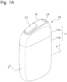
- FIG. 1A is a general perspective view of the inhaler 10
- Fig. 1B is a general perspective view of the inhaler 10 in the state that it is holding an aerosol generation base-material
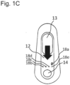
- Fig. 1C is a top view of the inhaler 10 viewed from the side that the aerosol generation base-material is to be inserted therein.
- an aerosol generation base-material which comprises an aerosol source and a flavor generation base-material such as a filling article or the like comprising a flavor source, is attached to the inhaler 10 in an attachable/detachable manner. Further, it is constructed in such a manner that aerosol having flavor is generated by heating the attached inhalation article 110.
- the aerosol generation base-material is an example of the inhalation article 110 (In the following description, the aerosol generation base-materials may collectively be referred to as "inhalation articles").
- An aerosol source included in an aerosol generation base-material may be solid or liquid.
- the aerosol source may be liquid such as polyhydric alcohol, such as glycerin or propylene glycol, or water, or the like, for example.
- the aerosol source may comprise a tobacco raw material or an extract originated from a tobacco raw material, which releases a fragrance-inhaling-taste component when it is heated.
- the aerosol source may comprise a medicine that is to be sucked by a patient.
- the aerosol generation base-material may not comprise a flavor source, depending on intended use thereof.
- the inhaler 10 comprises a top housing 11A, a bottom housing 11B, a cover 12, a shutter 13, a manipulation button 14, and an indicator 18.
- the outermost housing 11 of the inhaler 10 is constructed by connecting the top housing 11A and the bottom housing 11B to each other.
- the housing 11 may have a size that fits in a hand of a user. In the above case, when a user uses the inhaler 10, the user may hold the inhaler 10 by a user's hand, and suck aerosol.
- the top housing 11A comprises an opening (which is not shown in the figures), and the cover 12 is coupled to the top housing 11A in such a manner that it closes the opening.
- the cover 12 has an opening 12a, into which the inhalation article 110 can be inserted.
- the shutter 13 is constructed to open/close the opening 12a of the cover 12.
- the shutter 13 be a sliding-type shutter.
- the shutter 13 is attached to the cover 12, and constructed to be able to move, along a surface of the cover 12, between a first position for closing the opening 12a and a second position for opening the opening 12a.
- the shutter 13 is in the first position, and the opening 12a will be opened by a user by putting a user's finger on the shutter 13 and sliding it in the direction of the arrow.
- the inhalation article 110 is inserted in the opening 12a, a reception unit 42 opposite to the opening 12a receives the inhalation article 110, and a filling article in the inhalation article 110 is held in the inside thereof.
- the manipulation button 14 is used, for example, for switching between an ON state and an OFF state of an electric power source of the inhaler 10.
- a user can make electric power be supplied form an electric power supply 20 to a heater 40 to heat the inhalation article 110, by pressing (long pressing) the manipulation button 14 during a state that the inhalation article 110 is being inserted in the opening 12a as shown in Fig. 1B .
- aerosol is generated from an aerosol source included in the inhalation article 110, and flavor in a flavor source is taken in the aerosol.
- a user can suck aerosol including flavor, by performing suction action applied to a part of the inhalation article 110 projecting from the inhaler 10.
- the direction of insertion of the inhalation article 110 which is an aerosol generation base-material, into the opening 12a is referred to as a longitudinal direction of the inhaler 10.
- the heater 40 comprises a heating assembly 41 extending in the longitudinal direction.
- the heating assembly 41 comprises plural cylindrical members and is formed to have a cylindrical body as a whole.
- the heating assembly 41 is constructed to be able to receive therein a part of the inhalation article 110, and has a function for defining a flow path of air supplied to the inhalation article 110 and a function for heating the inhalation article 110 from an outer periphery thereof.
- the heater may be constructed in such a manner that the heating assembly 41 is arranged to heat, in a radial direction from a center axis in the longitudinal direction, the inhalation article 110.
- a vent 15 for taking air is formed for making the air flow into the inside of the heating assembly 41.
- the vent 15 is in fluid communication with one end part of the heating assembly 41 (the end part on the left side in Fig. 2 ).
- the inhaler 10 comprises a cap 16 which is attachable/detachable to/from the vent 15.
- the cap 16 is constructed in such a manner that air can flow into the inside of the heating assembly 41 from the vent 15 even in the state that the cap 15 is being attached to the vent 15, and, for example, the cap 16 may have a through hole, a notch, or the like (none of them is shown in the figures).
- vent 15 is constructed in the example in Fig. 2 in a position that makes the flow path have a straight-line shape
- the construction is not limited to the above construction.
- the suction opening part 110B comprises a paper tube part 114, a filter 115, and a hollow segment part 116 positioned between the paper tube part 114 and the filter 115.
- the hollow segment part 116 comprises a filling layer including one or plural hollow channels, and a plug wrapper for covering the filling layer. Since the density of filled fibers in the filling layer is high, air and aerosol flows through the hollow channel only, and almost no air and aerosol flows through the filling layer, when suction action is performed.
- the inhalation article 110 if it is desired to lower a decrease in the quantity of delivery of aerosol due to filtering of the aerosol components in the filter 115, shortening the length of the filter 115 and replacing that part by the hollow segment part 116 will be effective for increasing the quantity of delivery of the aerosol.
- the suction opening part 110B comprises three segments.
- the suction opening part 110B may be constructed by using one or two segments, or may be constructed by using four or more segments.
- the longitudinal-direction length of the inhalation article 110 it is preferable to set it to 40-90 mm, more preferable to set it to 50-75 mm, and still more preferably to set it to 50-60 mm.
- the circumference of the inhalation article 110 it is preferable to set it to 15-25 mm, more preferable to set it to 17 mm to 24 mm or less than 24 mm, and still more preferably to set it to 20-22 mm.
- the length of the base-material part 110A may be 20 mm
- the length of the first rolling paper 112 may be 20 mm
- the length of the hollow segment part 116 may be 8 mm
- the length of the filter 115 may be 7 mm.
- the length of each of the above segments may be changed appropriately, according to suitability to manufacture, required quality, and so on.
- the filling article 111 in the inhalation article 110 may comprise an aerosol source which generates aerosol when it is heated at predetermined temperature.
- the kind of the aerosol source is not specifically limited, and extracted material and/or components thereof, that are obtained from various natural products, may be selected as an aerosol source according to intended use.
- glycerin, propylene glycol, triacetin, 1,3-butanediol, and a mixture thereof, and so on are those that are expected to be used as aerosol sources.
- the filling article 111 in the inhalation article 110 may comprise shredded tobacco as a flavor source.
- the material of shredded tobacco is not specifically limited, and publicly known material such as a lamina, a stem, and so on may be used as the material.
- the range of the content of the filling article 111 in the inhalation article 110, in the case that the circumference is 22 mm and the length is 20 mm, is, for example, 200-400 mg, and is preferably 250-320 mg.
- the water content of the filling article 111 is, for example, 8-18 weight percent, and is preferably 10-16 weight percent.
- the water content is that explained above, occurrence of staining at the time of rolling is suppressed, and suitability to rolling at the time of manufacture of the base-material part 110A is made satisfactory.
- the size, the preparation method, and so on of the shredded tobacco used as the filling article 111 There is no special limitation with respect to the size, the preparation method, and so on of the shredded tobacco used as the filling article 111.
- dried tobacco leaves cut into pieces, each having the width of 0.8-1.2 mm may be used.
- dried tobacco leaves are crushed and uniformized to become particles, regarding those the average particle size is approximately 20-200 ⁇ m, and the particles are processed to become a sheet; and the sheet cut into pieces, each having the width of 0.8-1.2 mm, may be used.
- the above sheet formed via the sheet process may be processed to gather it without cutting it, and the gathered sheet may be used as the filling article 111.
- Each sheet of the first and second rolling paper 112 and 113 in the inhalation article 110 may be constructed by use of base paper which has the basis weight of, for example, 20-65 gsm, and, preferably, 25-45 gsm.
- the thickness of each sheet of the first and second rolling paper 112 and 113 is not specifically limited, however, in view of rigidness, gas permeability, and easiness of adjustment at the time of paper manufacture, the thickness is set to 10-100 ⁇ m, preferably to 20-75 ⁇ m, and, more preferably to 30-50 ⁇ m.
- Filler may be included in the first and second rolling paper 112 and 113 in the inhalation article 110.
- the filler content may be equal to or greater than 10 weight percent and less than 60 weight percent, and, may preferably be 15-45 weigh percent, with respect to the total weight of the first rolling paper 112 and the second rolling paper 113. It is preferable that the filler be 15-45 weight percent, with respect to a preferable range of basis weight (25-45 gsm).
- basis weight 25-45 gsm
- calcium carbonate, titanium dioxide, kaolin, and so on may be used as filler.
- Paper including filler such as that explained above presents a white color that is preferable in view of appearance of paper used as rolling paper of the inhalation article 110, and is able to keep its whiteness permanently.
- the ISO whiteness of rolling paper can be raised to 83 % or more, for example.
- the first rolling paper 112 and the second rolling paper 113 have the tensile strength of 8N/15mm or more.
- the tensile strength can be increased by reducing the filler content. Specifically, it can be increased by reducing the filler content to that less than the upper limit of the filler content shown with respect to each range of the basis weight illustrated in the above description.
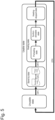
- Fig. 4 is a block diagram which schematically shows a construction of the inhaler 10.
- the inhaler 10 comprises the electric power supply 20, the heater 40, the reception unit 42, the controller 50, the notifier 60, a sensor 70, a memory 80, and a connector 90.
- the electric power supply 20 is constructed to supply electric power to respective components such as the heater 40, the controller 50, the notifier 60, the sensor 70, the memory 80, the connector 90, and so on. Especially, for heating the inhalation article 110, the electric power supply 20 supplies electric power to the heater 40 by outputting power instructed, in accordance with a preset heating profile, by the controller. In a different construction, the electric power supply 20 may be constructed in such a manner that it is connected to a different device comprising an electric power source 21.
- the heater 40 resistance heating takes place therein as a result that electric power is supplied thereto from the electric power supply 20 and current is thereby applied to the load. Thereafter, as a result that heat is transferred from the outer periphery to the inside of the reception unit 42, the inhalation article 110 which has been received by the reception unit 42 is heated.
- the reception unit 42 is constructed in such a manner that it receives the inhalation article 110 through the opening 12a in the direction of the arrow shown in the figure, and holds the filling article 111.
- the controller 50 is constructed to control operation of the inhaler 10. Further, the controller 50 is constructed to communicate information between it and respective components included in the inhaler 10.
- the controller 50 may be an electronic circuit module constructed as a microprocessor or a microcomputer.
- the controller 50 is programmed to control operation of the inhaler 10 in accordance with computer-executable instructions stored in the memory 80. Also, the controller 50 reads data from the memory 80 and uses the data for controlling operation of the inhaler 10, or stores data in the memory 80.
- the controller 50 is constructed to control operation of the inhaler 10, in accordance with plural heating profiles stored in the memory 80.
- the controller 50 performs heating operation corresponding to a specified heating profile.
- the heating operation includes preheating operation that is in common among plural heating profiles.
- the common preheating operation includes preheating operation for raising temperature and preheating operation for keeping temperature.
- the controller 50 makes the electric power supply 20 supply a quantity of electric power, that is in common among plural heating profiles, to the heater 40 to thereby raise the temperature of the heater 40 to the highest heating temperature that is substantially identical to the highest heating temperature in the plural heating profiles.
- the temperature-keeping preheating operation maintains the temperature at the substantially identical predetermined highest heating temperature during a predetermined heating period that is in common among plural heating profiles.
- the state that two degrees of temperature are "substantially identical” refers to a state that, even if two temperature values are not strictly equal to each other, the difference between the two degrees of temperature is that within a range of temperature, wherein the above difference is difference that a user does not feel any change (in terms of flavor) due thereto during the user's suction experience.
- a temperature difference less than 20 degrees Celsius may also be considered as a condition to judge whether degrees of temperature are those included in the range of substantially identical temperature.
- the inhaler 10 of the present embodiment realizes preheating operation that is in common among plural heating profiles based on operation modes.
- the period of time required to make the inhaler 10 allow a suction action is made to be in common among plural operation modes. That is, a user can make the inhaler 10 allow a suction action at same timing, without specially considering switching between operation modes, so that the user feels that it is intuitive and easy to use, and the quality of inhalation experience can be improved.
- the controller 50 may comprise therein a timer 55, and may be constructed to measure a desired period of time based on a clock (for example, a RTC (real time clock)).
- a clock for example, a RTC (real time clock)
- the controller 50 may measure, by using the timer, various kinds of operation periods such as a period during that electric power is supplied from the electric power supply 20 to the heater 40, a period during that the heater 40 is detected such that desired temperature is maintained by a temperature detector 72, and a period during that suction action is detected by an inhalation detector 74.
- the notifier 60 is constructed to provide a user with explicit notification. Especially, notification action corresponding to operation states and/or state transitions of the inhaler 10 is performed. Specifically, it is preferable that the notifier 60 provide a user with notification in various forms, by light emission, display, vocalization, vibration, and any arbitrary combination thereof.
- the notifier 60 may comprise plural LEDs 18a-18e, and each LED may provide various light-emission patterns (turning on, turning off, and repeatedly turning on and off) by using light having one or more colors. Further, the notifier 60 may comprise a vibrating motor and provide various vibration patterns, and may combine the vibration patterns with the light-emission patterns of the LEDs 18a-18e.
- the notifier 60 may comprise a switching-of-mode notifier 62, a preheating-period notifier 64, a completion-of-preheating notifier 66, and a heating-period notifier 68, and each of them may be constructed to include all or part of the LEDs 18a-18e and the vibrating motor.
- the controller 50 may make the switching-of-mode notifier 62 perform notification action with respect to switching between plural operation modes. For example, regarding switching, the switching may be indicated to a user by making the LSD 18a emit light having different colors according to respective operation modes, and, at the same time, making the vibrating motor vibrate by a second notifier.
- a user can grasp, based on vibration generated in the inhaler 10, completion of switching between plural operation modes.
- the controller 50 may make the preheating-period notifier 64 perform, in different notification forms, notification action with respect to a period during that temperature-raising preheating operation is being performed and a period during that temperature-keeping preheating operation is being performed. For example, in the period during that temperature-raising preheating operation is being performed, three LEDs 18a-c may be actuated in a stepwise manner over the time to emit light; and, in the period during that temperature-keeping preheating operation is being performed, five LEDs 18a-e may be actuated in a stepwise manner over the time to emit light, to thereby indicate, to a user, steps in the preheating operation period. That is, different light emission patterns formed by combinations of plural LEDs may be created.
- the controller 50 may make the completion-of-preheating notifier 66 perform, in response to expiration of the preheating operation period, notification action with respect to completion of preheating operation. For example, it is possible to indicate completion of preheating operation to a user, by making the vibrating motor vibrate for one second. By the above construction, the user can grasp, based on vibration generated in the inhaler 10, completion of preheating operation.
- the controller may make the heating-period notifier 68 indicate to a user, during a period of time-of-suction heating operation performed after the preheating operation, steps in the heating period by performing a process to make the five LEDs 18a-e emit light in a stepwise manner over the time.
- a specific point in time relating to inhalation such as a point in time that is 30 seconds before expiration of the time-of-suction heating operation, a point in time when a heating period has just expired, or the like.
- the preheating operation is set to be in common among plural heating profiles. Further, during the time from a start of preheating operation to completion of the preheating operation period, notification operation is performed by the preheating-period notifier 64 and the completion-of-preheating notifier 66 at timing that is in common among plural heating profiles. That is, in the preheating operation, notification action that is in common among plural heating profiles is performed, and a user is provided with a notification. Especially, with respect to a user who has been notified of completion of preheating at common timing, the user can proceed to a following suction action without feeling difference between plural operation modes. That is, the inhaler 10 of the present embodiment is advantageous in the points that a user feels that it is intuitive and easy to use; and the quality of inhalation experience can be improved.
- the sensor 70 is constructed to detect various kinds of operation states of the inhaler 10.
- the sensor 70 comprises a temperature detector 72, an inhalation detector 74, a pressing-force detector 76, and an open-state detector 78.
- the temperature detector 72 is constructed to detect temperature of the heater 40 (in more detail, a load included in the heater 40).
- the temperature detector is constructed to detect a value that is required for obtaining a resistance value of the load of the heater 40 (the value of current flowing through the load in the heater 40, the value of a voltage applied to the load in the heater 40, and so on).
- the temperature of the heater 40 can be estimated based on the detected resistance value of the load in the heater 40.
- the temperature detector may comprise a temperature sensor for detecting the temperature of the heater 40.
- the inhalation detector 74 is constructed to detect a series of suction actions performed by a user through the suction opening part 110B, by using a pressure sensor for detecting change in pressure or a flow rate sensor for detecting a flow rate in an aerosol flow path and/or an air taking-in flow path from the vent 15 to the heating assembly 41.
- the controller 50 can determine, by using the inhalation detector 74, the number of times of suction actions and/or the length of time of suction action performed by a user.
- the inhalation detector 74 may be constructed to detect suction action by using a weight sensor for detecting the weight of components in the inhalation article 110. In a different construction, in the case that the aerosol source is liquid, it may be constructed to detect the height of an internal liquid surface.
- the pressing-force detector 76 is constructed to detect performed action of pressing of the manipulation button 14 by a user. Specifically, when a user has pressed the manipulation button 14, an event that a part of the manipulation button 14 has been brought into contact with the second circuit board 32 positioned close thereto is detected.
- the controller 50 performs, in response to detection by the pressing-force detector 76, switching between plural operation modes based on plural heating profile. Specifically, it is preferable that the controller 50 be constructed to perform switching between plural operation modes, in response to detection, by the pressing-force detector 76, of an event that the manipulation button 14 has been pressed a predetermined number of times within a predetermined period of time. That is, a user can customize, by herself/himself, inhalation experience according to preference of the user; and convenience of the inhaler 10 can also be improved.
- the open-state detector 78 is constructed to detect a state that the opening 12a is being opened (or closed) by the shutter 13. Specifically, judgment as to whether the shutter 13 is in a first position for closing the opening 12a or in a second position for opening the opening 12a on the cover 12 is performed mechanically. In the present embodiment, the open-state detector 78 detects an opening state of the opening 12a; and the controller 50 is constructed to perform switching between plural operation modes only when the opening 12 is being opened.
- the senor 70 may be used for detecting an SOC (State of Charge, a charge state) of the electric power supply 20, a discharge state of the electric power supply 20, an integrated current value, a voltage, and so on.
- the integrated current value may be obtained by using a current integration method, an SOC-OCV (Open Circuit Voltage, open circuit voltage) method, or the like.
- the memory 80 is a storage medium such as a ROM (Read Only Memory), a RAM (Random Access Memory), a flash memory, or the like, and is constructed to store various kinds of data, including computer executable instructions, relating operation of the inhaler 10.
- the memory 80 may store data relating to plural heating profiles.
- the heating profile is setting data that defines an operation mode of the inhaler 10, and, especially, defines, based on heating information that includes heating temperature and heating time, a heating operation mode of heating from a start to an end thereof performed by the heater 40.
- the controller 50 makes the electric power supply 20 supply electric power to the heater 40 according to such a heating profile.
- the heating profile may be set individually according to each type of flavor included in an inhalation article, or may be allowed to be set manually by a user.
- the memory 80 stores, in addition to computer executable instructions, setting data that are necessary for controlling operation of the inhaler 10, and programs such as firmware and so on.
- the memory 80 may store a method for controlling the notifier 60 (modes of light emission, vocalization, vibration, etc., and so on), and data relating to values detected by the sensor 70, and so on.
- the setting data may be allowed to be set via input by a user.
- the connector 90 is used when connecting the inhaler 10 to an external device for allowing communication between them.
- Communication in this case may be wired communication and/or wireless communication.
- wired communication it is constructed that data relating to operation of the inhaler 10 is inputted/outputted to/from an external device by connecting a data transmission cable of micro-USB or the like by using an external connection terminal (the terminal 22).
- communication using the connector 90 is wireless communication, communication includes near field communication using Bluetooth (for example, BLE, Bluetooth Low Energy) and so on; and the connector 90 is constructed as a communication module.
- the inhaler 10 when the inhaler 10 is connected to an external input device via the terminal 22, various kinds of setting data and/or firmware of the inhaler 10, that have been stored in the memory 80, are rewritable based on instructions from the external input device.
- the inhaler 10 in such a manner that information, that relates to modes of control of the notifier 60 (light emission, vocalization, vibration, and so on) and parts of heating profiles at the time of suction (a range of temperature, heating time, the number of suction actions, and so on that are allowable at the time of heating), is rewritable via the connector 90.
- FIG. 5 relates to heating operation performed by the inhaler 10, and is an example of state transition of the inhaler 10 corresponding to manipulation performed by a user.
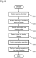
- Fig. 6 is a flow chart of the whole heating operation performed by the inhaler 10.
- the above states are mere examples, and that it is natural that many states exist in addition to the respective states specifically shown in Fig. 5 .
- the states of the inhaler 10 include an "unusable state” and a “usable state.”
- the inhaler 10 changes its state between the above states in response to manipulation performed by a user.
- the "usable state” includes a "stand-by state,” a “heating state,” and a “heating-stopped state,” and, during the heating operation, the inhaler 10 can change its state in the above order of the states in response to manipulation performed by a user.
- the heating state includes a preheating state and a suction-allowable state following the preheating state.
- An initial state of the inhaler 10 is that wherein a user has not yet performed any manipulation applied to the inhaler 10, and the inhaler 10 is in the "unusable state" wherein it has not yet been operated (START).
- a user opens the shutter 13 of the inhaler 10 (OP1).
- the open-state detector 78 detects an event that the shutter has opened the opening 12a (step S10).
- step S10 the inhaler 10 is activated, and the state thereof is changed to the "stand-by state” in the "usable state.”
- the notifier 60 may operate the LED 18a to emit light having colors corresponding to the present operation mode.
- the "stand-by state” is a state before execution of heating operation by the inhaler 10, specifically, a state during that starting of preheating operation is waited for.
- the user inserts an inhalation article 110 in the opening 12a.
- the reception unit 42 receives therein the inhalation article 110 (step S20).
- one of plural heating profiles stored in the memory 80 is selected and enabled (step S30), before heating operation of the inhaler 10 is performed.
- Plural operation modes are associated with plural heating profiles, respectively, and the user herself/himself can decide an operation mode used to operate the inhaler 10.
- the plural operation modes includes a "standard mode” and a "power mode.”
- the "standard mode” is a heating mode wherein the user can taste a stable flavor continuously.
- the "power mode” is a heating mode during that the user can have more powerful inhalation experience than that provided during the "standard mode,” and, in the mode, it is intended to provide a user with higher-quality inhalation experience per single inhalation article 110.
- the operation mode be set to the "standard mode,” and a heating profile corresponding to the "standard mode” be enabled. It is possible to set it in such a manner that a user selectively switches the mode between the "standard mode” and the "power mode” via manipulation for switching the operation mode (OP2).
- the switching manipulation may be action of successively pressing the manipulation button 14 a predetermined number of times within a predetermined period of time; for example, the manipulation may be that wherein pressing actions are performed two times within a period of 1000 milliseconds after a first pressing action is applied to the manipulation button 14 (in this case, a total of three times of pressing actions are performed successively).
- a heating profile corresponding to the selected operation mode is enabled.
- the switching manipulation is detected by the pressing-force detector 76, and, in response thereto, notification action is performed by the switching-of-mode notifier 62.
- the controller 50 makes the switching-of-mode notifier 62 notify switching between plural operation modes.
- the user performs manipulation to press the manipulation button 14 (OP3).
- the manipulation may be long pressing manipulation that is action to press the manipulation button 14, for example, for two seconds or more.
- Such action of pressing of the manipulation button 14 is detected by the pressing-force detector 76. That is, the pressing-force detector 76 detects a trigger used to start heating of the inhalation article 110 (step S40).
- the "preheating state" in the “heating state” is a state in the preheating operation period that is from the time of a start of supplying of electric power from the electric power supply 20 to the heater 40 to the time when the state becomes the "suction-allowable state" during that the inhalation article 110 can generate aerosol.
- the heater 40 performs preheating operation for preheating the inhalation article 110 (step S50).
- notification action is performed by the preheating-period notifier 64.
- notification action with respect to completion of preheating is performed by the completion-of-preheating notifier 66.
- details of the preheating operation in the preheating operation period will be explained later.
- the state of the inhaler 10 is automatically changed following thereto from the "preheating state” to the "suction-allowable state.”
- the "suction-allowable state” is a state that the inhaler 10 can generate aerosol in response to completion of the preheating operation, and is also a state during that suction action performed by a user is acceptable.
- the heater 40 performs time-of-suction heating operation to heat the inhalation article 110 to thereby generate inhaled components (step S60).
- the state of the inhaler 10 is automatically changed to the "heating-stopped state.”
- the "heating-stopped state” is a state during that supplying of electric power from the electric power supply 20 to the heater 40 is stopped, and suction action performed by a user is still acceptable. That is, certain operation, that is performed after the electric power supply 20 is controlled by the processor to stop supplying of electric power, may be included in the time-of-suction heating operation.
- notification action is performed by the heating-period notifier 68. Further, after expiration of the period of time-of-suction heating operation, notification action with respect thereto may be performed, similarly. Details of the time-of-suction heating operation will be explained later.
- the user After expiration of the period of the time-of- suction heating operation, the user closes the shutter 13 of the inhaler 10, finally (OP4).
- the open-state detector 78 detects the event that the shutter has closed the opening 12a, and the state of the inhaler 10 is changed from the "usable state” to the "unusable state,” to return to the initial state (END).
- Fig. 7 is a graph of an example heating profile corresponding to the "standard mode" in the inhaler 10
- Fig. 8 is a graph of an example heating profile corresponding to the "power mode.”
- Fig. 9 is a schematic flow chart of preheating operation in heating operation performed by the inhaler
- Fig. 10 is a schematic flow chart of time-of-suction heating operation.
- the heating profiles in Fig. 7 and Fig. 8 include profiles corresponding to preheating operation and time-of-suction heating operation.
- each of the example heating profiles in Fig. 7 and Fig. 8 is defined in such a manner that it is represented as a function having a convex shape. That is, after starting of heating of the inhaler 10, the quality of user's inhalation experience is gradually improved; and, further, at certain timing, a user's feeling of satisfaction reaches its peak. Thereafter, the satisfaction peaks out and declines gradually. That is, a user can intuitively estimate the time when a smoking-allowable period expires. Thus, the quality of user's inhalation experience can be further improved.
- the preheating operation starts in response to an event that a trigger for starting heating of the inhalation article 110 is detected in step S40.
- the controller 50 makes the temperature detector 72 start detection of temperature of the heater 40, and makes the internal timer 55 start measurement (step S52).
- the controller 50 performs temperature-raising preheating operation. Specifically, the controller 50 makes the electric power supply 20 supply electric power to the heater 40 to thereby raise the temperature of the heater 40 to predetermined heating temperature.
- electric power specifically, the highest output power of the electric power supply 20 during the preheating operation, is supplied from the electric power supply 20 to the heater 40 to thereby raise the temperature of the heater 40 to the predetermined highest heating temperature (step S54).
- the quantity of electric power supplied from the electric power supply 20 to the heater 40 relating to the heating profile of the "standard mode” is the same as that relating to the heating profile of the "power mode.”
- the predetermined highest heating temperature is the predetermined highest heating temperature that can be detected by the temperature detector 72 in the heating profile of the "standard mode” and the heating profile of the "power mode,; and it is preferable that the above temperature be set to 240 degrees Celsius, for example.
- the time t 0 changes according to the magnitude of the highest output power of the electric power supply 20 during the preheating operation.
- the controller 50 uses the temperature detector 72 and the timer 55 to judge whether the temperature of the heater 40 has reached the predetermined highest heating temperature (step S55). If the temperature of the heater 40 has not yet reached the predetermined highest heating temperature (No), the operation in step S54 is continued for at most 30 seconds. In this regard, in the case that the temperature of the heater 40 did not reach the predetermined highest heating temperature after a lapse of 30 seconds, it is preferable to stop the preheating operation based on supposition that the quantity of the output power of the electric power supply 20 is insufficient.
- step S55 If the temperature of the heater 40 has reached the predetermined highest heating temperature in step S55 (Yes), the controller 50 performs temperature-keeping preheating operation, that follows the temperature-raising preheating operation. Specifically, the controller 50 continues high-temperature heating for keeping the temperature of the heater 40 at the highest heating temperature for a certain period of time (step S56).
- the temperature-keeping preheating operation relating to the heating profile of the "standard mode” is the same as that relating to the heating profile of the "power mode.” Specifically, constant period of time t 1 during that the highest heating temperature, that is 240 degrees Celsius, is to be kept is in common among the heating profiles; and, for example, it is preferable that the above period of time be set to that within a range between 10 seconds and 15 seconds (14 seconds, in this example) ( Fig. 7 and Fig. 8 ).
- step S57 If the length of time of the period during that the high-temperature heating for keeping the temperature is being performed has reached the constant period of time t 1 and the temperature-keeping preheating operation period has expired in step S57 (Yes), the controller 50 terminates the preheating operation, and, following thereto, starts the heating operation at the time of suction.
- the heating operation at the time of suction is performed as shown in Fig. 10 , if the preheating operation period has expired (step S57, Yes).
- the controller 50 continues high-temperature heating for further keeping the highest heating temperature of the heater 40 that has been kept by the temperature-keeping preheating operation (step S61).
- a constant period of time t 2 during that high-temperature heating is continued for keeping the temperature, relating to the heating profile of the "standard mode” be set differently from that relating to the heating profile of the "power mode.”
- the constant period of time t 2 during that the highest heating temperature of 240 degrees Celsius is to be kept it is preferable that it be set to 1 second with respect to the heating profile of the "standard mode” ( Fig. 7 ).
- the heating profile of the "standard mode” it is not necessary for the heating profile of the "standard mode” to provide a user with powerful inhalation experience that is as powerful as that provided by the heating profile of the "power mode.” That is, in view of a feeling of satisfaction that a user is provided with, the constant period of time t 2 , during that the highest heating temperature is to be kept, in the heating profile of the "standard mode” may be set to be shorter than the constant period of time t 2 in the heating profile of the "power mode.”
- the controller 50 terminates, in the time-of-suction heating operation, the high-temperature heating operation for keeping the highest heating temperature, and starts operation for lowering the temperature. Specifically, for lowering, at a predetermined rate, the temperature of the heater 40 to predetermined temperature, the controller 50 performs control in such a manner that heating for lowering the temperature is performed for a constant period of time t 3 (step S63). It is preferable that the constant period of time t 3 for lowering the temperature relating to the heating profile of the "standard mode" be set differently from that relating to the heating profile of the "power mode.”
- the constant period of time t 3 in the case of the heating profile of the "standard mode” be set to that within a range between 30 seconds and 50 seconds (45 seconds, in this example) ( Fig. 7 ).
- it in the case of the heating profile of the "power mode” be set to that within a range between 60 seconds and 90 seconds (80 seconds, in this example) ( Fig. 8 ).
- the temperature of the heater 40 be lowered to 200 degrees Celsius in the heating profile of the "standard mode,” and, on the other hand, it is preferable that the temperature be lowered to 205 degrees Celsius in the heating profile of the "power mode.”
- 200 degrees Celsius may be regarded as temperature that is substantially identical with 205 degrees Celsius, as explained above. This is because the temperature difference between them is a difference that does not bring a user to feel change (in terms of flavor).
- the constant period of time t 3 in the heating profile of the "standard mode” may be set to be that shorter than the constant period of time t 3 in the heating profile of the "power mode.”
- the degrees of temperature to be lowered the to-be-lowered degrees relating to the heating profile of the "standard mode” may be set to be that lower than that relating to the heating profile of the "power mode.”
- step S64 If the length of time of the period during that the heating is being performed for lowering the temperature has reached the constant period of time t 3 in step S64 (Yes), the controller 50 terminates the temperature-lowering operation, and starts low-temperature heating operation in the time-of-suction heating operation. Specifically, for a period of time until supplying of electric power to the heater 40 is stopped, the controller 50 makes the low-temperature heating be continued for keeping the temperature of the heater 40 at the temperature that has been achieved as a result of temperature lowering in step S63 (step S65). It is preferable that a constant period of time t 4 for low-temperature heating relating to the heating profile of the "standard mode" be set differently from that relating to the heating profile of the "power mode.”
- the constant period of time t 4 in the case of the heating profile of the "standard mode” be set to 214 seconds in this example ( Fig. 7 ).
- it in the case of the heating profile of the "power mode” be set to 144 seconds in this example ( Fig. 8 ). That is, regarding the constant period of time t 4 , the length of time that the low temperature is kept in the case of the heating profile of the "standard mode” is longer than that in the case of the heating profile of the "power mode," and the above matter suits a point of view of the degree of satisfaction that a user is provided with.
- the controller 50 terminates the low-temperature heating, and stops supplying of electric power from the electric power supply 20 to the heater 40 in the time-of-suction heating operation. Specifically, the controller 50 performs control in such a manner that supplying of electric power is stopped for a constant period of time t 5 to thereby lower the temperature of the heater 40 (step S67).
- the constant period of time t 5 be set, to be in common among the heating profile of the "standard mode” and the heating profile of the "power mode,” to 144 seconds ( Fig. 8 and Fig. 9 ).
- the controller 50 finally terminates the time-of-suction heating operation (END). It is preferable that, in this example, the duration of a series of the time-of-suction heating operation be set, to be in common among the heating profile of the "standard mode” and the heating profile of the "power mode,” to 270 seconds ( Fig. 8 and Fig. 9 ).
- the certain periods of time t 1 -t 5 that are set in relation to heating profiles, are set to predetermined values.
- the constructions are not limited to those explained above, and, in a modification example, the number of times of user's suction actions may be set instead of information of the certain periods of time t 1 -t 5 , for example.
- the controller 50 make the inhalation detector 74 detect the number of times of suction actions during user's inhalation action.
- the values of the heating temperature and the heating periods in the example heating profiles in Fig. 7 and Fig. 8 are mere examples; and a person skilled in the art will understand that, in actuality, in a point of view of the quality of inhalation experience that a user is provided with and/or in a point of view of the degree of satisfaction, the values can be set to various values according to characteristics of inhalation articles 110.
- the notifier 60 may comprise plural LEDs 18a-18e, and various types of light emission patterns (turning on, turning off, and repeatedly turning on and off) using one or more colors are created by each of the LEDs. Further, it is explained that it is possible to provide a vibrating motor to create various type of vibration patterns, and combine the vibration patterns with the light emission patterns of the plural LEDs 18a-18e.
- the constructions and the forms of notification of the notifier 60 are not limited to those explained above; and any construction which functions to provide a user with explicit notification can be used, and notification can be realized by light emission, vibration, display, and vocalization, and a combination thereof or the like. By the above construction, a more flexible notification mode can be realized for a user.
- the notifier 60 may comprise, in addition to the plural LEDs 18a-18e and the vibrating motor, one or more speakers, and may be constructed to provide a user with notification based on sound.
- the notifier 60 may comprise one or more displays, and may be constructed to provide a user with notification by displaying letter/image information on the display(s).
- Controller 60 ... Notifier: 62 ... Switching-of-mode notifier: 64 ... Preheating-period notifier: 66 ... Completion-of-preheating notifier: 68 ... Heating-period notifier: 70 ... Sensor: 72 ... Temperature detector: 74 ... Inhalation detector: 76 ... Pressing-force detector: 78 ... Open-state detector: 80 ... Memory: 90 ... Connector Further examples of the invention are as follows
Landscapes
- Thermotherapy And Cooling Therapy Devices (AREA)
- Medicinal Preparation (AREA)
- External Artificial Organs (AREA)
- Massaging Devices (AREA)
Priority Applications (1)
| Application Number | Priority Date | Filing Date | Title |
|---|---|---|---|
| EP25179027.5A EP4581950A3 (de) | 2020-04-28 | 2020-04-28 | Aspirationsvorrichtung, -verfahren und -programm |
Applications Claiming Priority (3)
| Application Number | Priority Date | Filing Date | Title |
|---|---|---|---|
| EP20932954.9A EP4144244B1 (de) | 2020-04-28 | 2020-04-28 | Aspirationsvorrichtung, -verfahren und -programm |
| EP25179027.5A EP4581950A3 (de) | 2020-04-28 | 2020-04-28 | Aspirationsvorrichtung, -verfahren und -programm |
| PCT/JP2020/018141 WO2021220410A1 (ja) | 2020-04-28 | 2020-04-28 | 吸引装置、方法、及びプログラム |
Related Parent Applications (2)
| Application Number | Title | Priority Date | Filing Date |
|---|---|---|---|
| EP20932954.9A Division EP4144244B1 (de) | 2020-04-28 | 2020-04-28 | Aspirationsvorrichtung, -verfahren und -programm |
| EP20932954.9A Division-Into EP4144244B1 (de) | 2020-04-28 | 2020-04-28 | Aspirationsvorrichtung, -verfahren und -programm |
Publications (2)
| Publication Number | Publication Date |
|---|---|
| EP4581950A2 true EP4581950A2 (de) | 2025-07-09 |
| EP4581950A3 EP4581950A3 (de) | 2025-10-15 |
Family
ID=78332325
Family Applications (2)
| Application Number | Title | Priority Date | Filing Date |
|---|---|---|---|
| EP25179027.5A Pending EP4581950A3 (de) | 2020-04-28 | 2020-04-28 | Aspirationsvorrichtung, -verfahren und -programm |
| EP20932954.9A Active EP4144244B1 (de) | 2020-04-28 | 2020-04-28 | Aspirationsvorrichtung, -verfahren und -programm |
Family Applications After (1)
| Application Number | Title | Priority Date | Filing Date |
|---|---|---|---|
| EP20932954.9A Active EP4144244B1 (de) | 2020-04-28 | 2020-04-28 | Aspirationsvorrichtung, -verfahren und -programm |
Country Status (5)
| Country | Link |
|---|---|
| EP (2) | EP4581950A3 (de) |
| JP (1) | JP7338049B2 (de) |
| CN (1) | CN115460946A (de) |
| PL (1) | PL4144244T3 (de) |
| WO (1) | WO2021220410A1 (de) |
Families Citing this family (10)
| Publication number | Priority date | Publication date | Assignee | Title |
|---|---|---|---|---|
| US12520880B2 (en) | 2021-01-18 | 2026-01-13 | Altria Client Services Llc | Heat-not-burn (HNB) aerosol-generating devices including energy based heater control, and methods of controlling a heater |
| US20230146798A1 (en) * | 2021-11-05 | 2023-05-11 | Nicoventures Trading Limited | Aerosol provision system |
| KR102817087B1 (ko) | 2022-02-11 | 2025-06-05 | 주식회사 케이티앤지 | 에어로졸 생성 장치 및 이의 제어 방법 |
| WO2023157898A1 (ja) * | 2022-02-17 | 2023-08-24 | 日本たばこ産業株式会社 | 香味吸引器具又はエアロゾル生成装置、その制御方法及びそのプログラム |
| WO2023181281A1 (ja) * | 2022-03-24 | 2023-09-28 | 日本たばこ産業株式会社 | エアロゾル生成システム、制御方法、及びプログラム |
| EP4525653A1 (de) * | 2022-05-16 | 2025-03-26 | Philip Morris Products S.A. | Profilauswahl für aerosolerzeugungsvorrichtung |
| KR20250046300A (ko) * | 2022-08-04 | 2025-04-02 | 니뽄 다바코 산교 가부시키가이샤 | 에어로졸 생성 시스템, 제어 방법, 및 프로그램 |
| US12550942B2 (en) | 2022-09-19 | 2026-02-17 | Altria Client Services Llc | Session control system |
| KR20250099746A (ko) * | 2022-12-16 | 2025-07-02 | 니뽄 다바코 산교 가부시키가이샤 | 에어로졸 생성 장치 |
| KR20250094734A (ko) * | 2022-12-16 | 2025-06-25 | 니뽄 다바코 산교 가부시키가이샤 | 에어로졸 생성 장치 |
Citations (1)
| Publication number | Priority date | Publication date | Assignee | Title |
|---|---|---|---|---|
| JP2018534926A (ja) | 2015-10-15 | 2018-11-29 | ジェイティー インターナショナル エス.エイ. | 電子蒸気吸入器の作動方法 |
Family Cites Families (12)
| Publication number | Priority date | Publication date | Assignee | Title |
|---|---|---|---|---|
| TWI608805B (zh) * | 2012-12-28 | 2017-12-21 | 菲利浦莫里斯製品股份有限公司 | 加熱型氣溶膠產生裝置及用於產生具有一致性質的氣溶膠之方法 |
| US11013872B2 (en) * | 2013-12-19 | 2021-05-25 | Philip Morris Products S.A. | Aerosol-generating system for generating and controlling the quantity of nicotine salt particles |
| CN108601406B (zh) | 2016-02-25 | 2021-11-30 | 菲利普莫里斯生产公司 | 具有液位确定的气溶胶生成系统和确定气溶胶生成系统中的液位的方法 |
| MX2018014354A (es) * | 2016-05-25 | 2019-04-11 | Juul Labs Inc | Control de vaporizador electronico. |
| GB201612945D0 (en) * | 2016-07-26 | 2016-09-07 | British American Tobacco Investments Ltd | Method of generating aerosol |
| RU2738441C2 (ru) * | 2016-08-17 | 2020-12-14 | Филип Моррис Продактс С.А. | Генерирующее аэрозоль изделие, имеющее усовершенствованную обертку |
| KR102843313B1 (ko) * | 2017-06-28 | 2025-08-07 | 알트리아 클라이언트 서비시즈 엘엘씨 | 증발 장치 및 이를 이용한 화합물 전달 방법 |
| CN107296301A (zh) * | 2017-08-18 | 2017-10-27 | 深圳市卓力能电子有限公司 | 一种加热非燃烧电子烟的功率与温度分时控制方法及烟具 |
| CN108143006B (zh) * | 2018-01-12 | 2023-12-29 | 深圳市康泓威科技有限公司 | 自动控制的加热不燃型电子烟具及其控制方法 |
| CN108433186B (zh) * | 2018-03-30 | 2024-04-26 | 上海新型烟草制品研究院有限公司 | 一种气雾产生装置及其温度控制的方法 |
| WO2019227381A1 (zh) * | 2018-05-31 | 2019-12-05 | 绿烟实业(深圳)有限公司 | 控制气雾生成装置中气雾产生的方法和气雾生成装置 |
| KR102184703B1 (ko) * | 2018-08-01 | 2020-11-30 | 주식회사 케이티앤지 | 히터의 온도를 제어하는 방법 및 그 방법을 수행하는 에어로졸 생성 장치 |
-
2020
- 2020-04-28 EP EP25179027.5A patent/EP4581950A3/de active Pending
- 2020-04-28 PL PL20932954.9T patent/PL4144244T3/pl unknown
- 2020-04-28 EP EP20932954.9A patent/EP4144244B1/de active Active
- 2020-04-28 CN CN202080100348.1A patent/CN115460946A/zh active Pending
- 2020-04-28 WO PCT/JP2020/018141 patent/WO2021220410A1/ja not_active Ceased
- 2020-04-28 JP JP2022518496A patent/JP7338049B2/ja active Active
Patent Citations (1)
| Publication number | Priority date | Publication date | Assignee | Title |
|---|---|---|---|---|
| JP2018534926A (ja) | 2015-10-15 | 2018-11-29 | ジェイティー インターナショナル エス.エイ. | 電子蒸気吸入器の作動方法 |
Also Published As
| Publication number | Publication date |
|---|---|
| CN115460946A (zh) | 2022-12-09 |
| EP4144244C0 (de) | 2025-07-02 |
| EP4144244A4 (de) | 2024-01-10 |
| JPWO2021220410A1 (de) | 2021-11-04 |
| EP4144244A1 (de) | 2023-03-08 |
| WO2021220410A1 (ja) | 2021-11-04 |
| EP4581950A3 (de) | 2025-10-15 |
| PL4144244T3 (pl) | 2025-12-01 |
| EP4144244B1 (de) | 2025-07-02 |
| JP7338049B2 (ja) | 2023-09-04 |
Similar Documents
| Publication | Publication Date | Title |
|---|---|---|
| EP4144244B1 (de) | Aspirationsvorrichtung, -verfahren und -programm | |
| US12194235B2 (en) | Differential pressure sensor for an aerosol delivery device | |
| US20210360970A1 (en) | Suction device, device for controlling suction device, information processing method, and program | |
| EP3579709B1 (de) | Dampfbereitstellungssystem | |
| CN107249364B (zh) | 非燃烧式香味吸引器 | |
| EP3116335B1 (de) | Aerosolabgabesystem und zugehöriges verfahren, vorrichtung zur bereitstellung von kontrollinformationen für ein aerosolabgabesystem über eine patrone | |
| EP4268642A2 (de) | Detektion von ungünstigen heizerzuständen in einem elektrisch beheizten aerosolerzeugungssystem | |
| EP3973802A1 (de) | Aspirationsvorrichtung, aspirationserfahrungsbereitstellungssystem, verfahren und programm | |
| EP3542656A1 (de) | Aerosolabgabevorrichtung sowie zugehöriges verfahren und computerprogrammprodukt zur steuerung einer aerosolabgabevorrichtung basierend auf eingabemerkmalen | |
| JP7645967B2 (ja) | 蒸気供給システムおよび供給方法 | |
| EP3871531A1 (de) | Steuereinheit, aerosolerzeugungsvorrichtung, verfahren und programm zur steuerung des heizaggregats und rauchartikel | |
| JP7405487B2 (ja) | 蒸気供給システム | |
| JP7108790B2 (ja) | 吸引装置、電源ユニット、及び方法 | |
| TW202145909A (zh) | 產生可吸入氣霧的裝置 | |
| EP2967140A1 (de) | Heizungsregelungsanordnung für einen elektronischen rauchartikel sowie zugehöriges system und verfahren | |
| JP7511082B2 (ja) | エアロゾル生成装置、制御方法、及びプログラム | |
| CN116209366A (zh) | 具有多烟弹性能的便携式汽化器装置 | |
| CA3082062C (en) | STEAM SUPPLY SYSTEMS | |
| RU2800812C1 (ru) | Ингалятор и способ его работы | |
| CN120381154A (zh) | 气溶胶生成装置及其控制方法 | |
| EP3785553A1 (de) | Rauchersatzvorrichtung und steuerungsverfahren | |
| CA3164904C (en) | Vapour provision system | |
| KR20260000482A (ko) | 에어로졸 생성 장치 및 에어로졸 생성 장치의 제어 방법 | |
| RU2772840C1 (ru) | Блок управления, устройство генерации аэрозоля, способ управления нагревателем, машиночитаемый носитель данных и курительное изделие | |
| CN120322166A (zh) | 会话控制系统 |
Legal Events
| Date | Code | Title | Description |
|---|---|---|---|
| PUAI | Public reference made under article 153(3) epc to a published international application that has entered the european phase |
Free format text: ORIGINAL CODE: 0009012 |
|
| STAA | Information on the status of an ep patent application or granted ep patent |
Free format text: STATUS: REQUEST FOR EXAMINATION WAS MADE |
|
| 17P | Request for examination filed |
Effective date: 20250527 |
|
| AC | Divisional application: reference to earlier application |
Ref document number: 4144244 Country of ref document: EP Kind code of ref document: P |
|
| AK | Designated contracting states |
Kind code of ref document: A2 Designated state(s): AL AT BE BG CH CY CZ DE DK EE ES FI FR GB GR HR HU IE IS IT LI LT LU LV MC MK MT NL NO PL PT RO RS SE SI SK SM TR |
|
| REG | Reference to a national code |
Ref country code: DE Ref legal event code: R079 Free format text: PREVIOUS MAIN CLASS: A24F0040200000 Ipc: A24F0040570000 |
|
| PUAL | Search report despatched |
Free format text: ORIGINAL CODE: 0009013 |
|
| AK | Designated contracting states |
Kind code of ref document: A3 Designated state(s): AL AT BE BG CH CY CZ DE DK EE ES FI FR GB GR HR HU IE IS IT LI LT LU LV MC MK MT NL NO PL PT RO RS SE SI SK SM TR |
|
| RIC1 | Information provided on ipc code assigned before grant |
Ipc: A24F 40/57 20200101AFI20250911BHEP Ipc: A24F 40/20 20200101ALN20250911BHEP |