EP4580349A2 - Image sensor and electronic apparatus - Google Patents
Image sensor and electronic apparatus Download PDFInfo
- Publication number
- EP4580349A2 EP4580349A2 EP25173359.8A EP25173359A EP4580349A2 EP 4580349 A2 EP4580349 A2 EP 4580349A2 EP 25173359 A EP25173359 A EP 25173359A EP 4580349 A2 EP4580349 A2 EP 4580349A2
- Authority
- EP
- European Patent Office
- Prior art keywords
- wiring
- substrate
- image sensor
- pixel
- transistor
- Prior art date
- Legal status (The legal status is an assumption and is not a legal conclusion. Google has not performed a legal analysis and makes no representation as to the accuracy of the status listed.)
- Pending
Links
Images


















Classifications
-
- H—ELECTRICITY
- H10—SEMICONDUCTOR DEVICES; ELECTRIC SOLID-STATE DEVICES NOT OTHERWISE PROVIDED FOR
- H10F—INORGANIC SEMICONDUCTOR DEVICES SENSITIVE TO INFRARED RADIATION, LIGHT, ELECTROMAGNETIC RADIATION OF SHORTER WAVELENGTH OR CORPUSCULAR RADIATION
- H10F39/00—Integrated devices, or assemblies of multiple devices, comprising at least one element covered by group H10F30/00, e.g. radiation detectors comprising photodiode arrays
- H10F39/80—Constructional details of image sensors
- H10F39/813—Electronic components shared by multiple pixels, e.g. one amplifier shared by two pixels
-
- H—ELECTRICITY
- H04—ELECTRIC COMMUNICATION TECHNIQUE
- H04N—PICTORIAL COMMUNICATION, e.g. TELEVISION
- H04N25/00—Circuitry of solid-state image sensors [SSIS]; Control thereof
- H04N25/70—SSIS architectures; Circuits associated therewith
- H04N25/76—Addressed sensors, e.g. MOS or CMOS sensors
-
- H—ELECTRICITY
- H04—ELECTRIC COMMUNICATION TECHNIQUE
- H04N—PICTORIAL COMMUNICATION, e.g. TELEVISION
- H04N25/00—Circuitry of solid-state image sensors [SSIS]; Control thereof
- H04N25/70—SSIS architectures; Circuits associated therewith
- H04N25/76—Addressed sensors, e.g. MOS or CMOS sensors
- H04N25/77—Pixel circuitry, e.g. memories, A/D converters, pixel amplifiers, shared circuits or shared components
- H04N25/778—Pixel circuitry, e.g. memories, A/D converters, pixel amplifiers, shared circuits or shared components comprising amplifiers shared between a plurality of pixels, i.e. at least one part of the amplifier must be on the sensor array itself
-
- H—ELECTRICITY
- H04—ELECTRIC COMMUNICATION TECHNIQUE
- H04N—PICTORIAL COMMUNICATION, e.g. TELEVISION
- H04N25/00—Circuitry of solid-state image sensors [SSIS]; Control thereof
- H04N25/70—SSIS architectures; Circuits associated therewith
- H04N25/79—Arrangements of circuitry being divided between different or multiple substrates, chips or circuit boards, e.g. stacked image sensors
-
- H—ELECTRICITY
- H10—SEMICONDUCTOR DEVICES; ELECTRIC SOLID-STATE DEVICES NOT OTHERWISE PROVIDED FOR
- H10F—INORGANIC SEMICONDUCTOR DEVICES SENSITIVE TO INFRARED RADIATION, LIGHT, ELECTROMAGNETIC RADIATION OF SHORTER WAVELENGTH OR CORPUSCULAR RADIATION
- H10F39/00—Integrated devices, or assemblies of multiple devices, comprising at least one element covered by group H10F30/00, e.g. radiation detectors comprising photodiode arrays
- H10F39/011—Manufacture or treatment of image sensors covered by group H10F39/12
- H10F39/014—Manufacture or treatment of image sensors covered by group H10F39/12 of CMOS image sensors
-
- H—ELECTRICITY
- H10—SEMICONDUCTOR DEVICES; ELECTRIC SOLID-STATE DEVICES NOT OTHERWISE PROVIDED FOR
- H10F—INORGANIC SEMICONDUCTOR DEVICES SENSITIVE TO INFRARED RADIATION, LIGHT, ELECTROMAGNETIC RADIATION OF SHORTER WAVELENGTH OR CORPUSCULAR RADIATION
- H10F39/00—Integrated devices, or assemblies of multiple devices, comprising at least one element covered by group H10F30/00, e.g. radiation detectors comprising photodiode arrays
- H10F39/011—Manufacture or treatment of image sensors covered by group H10F39/12
- H10F39/018—Manufacture or treatment of image sensors covered by group H10F39/12 of hybrid image sensors
-
- H—ELECTRICITY
- H10—SEMICONDUCTOR DEVICES; ELECTRIC SOLID-STATE DEVICES NOT OTHERWISE PROVIDED FOR
- H10F—INORGANIC SEMICONDUCTOR DEVICES SENSITIVE TO INFRARED RADIATION, LIGHT, ELECTROMAGNETIC RADIATION OF SHORTER WAVELENGTH OR CORPUSCULAR RADIATION
- H10F39/00—Integrated devices, or assemblies of multiple devices, comprising at least one element covered by group H10F30/00, e.g. radiation detectors comprising photodiode arrays
- H10F39/10—Integrated devices
- H10F39/12—Image sensors
- H10F39/18—Complementary metal-oxide-semiconductor [CMOS] image sensors; Photodiode array image sensors
- H10F39/182—Colour image sensors
-
- H—ELECTRICITY
- H10—SEMICONDUCTOR DEVICES; ELECTRIC SOLID-STATE DEVICES NOT OTHERWISE PROVIDED FOR
- H10F—INORGANIC SEMICONDUCTOR DEVICES SENSITIVE TO INFRARED RADIATION, LIGHT, ELECTROMAGNETIC RADIATION OF SHORTER WAVELENGTH OR CORPUSCULAR RADIATION
- H10F39/00—Integrated devices, or assemblies of multiple devices, comprising at least one element covered by group H10F30/00, e.g. radiation detectors comprising photodiode arrays
- H10F39/10—Integrated devices
- H10F39/12—Image sensors
- H10F39/199—Back-illuminated image sensors
-
- H—ELECTRICITY
- H10—SEMICONDUCTOR DEVICES; ELECTRIC SOLID-STATE DEVICES NOT OTHERWISE PROVIDED FOR
- H10F—INORGANIC SEMICONDUCTOR DEVICES SENSITIVE TO INFRARED RADIATION, LIGHT, ELECTROMAGNETIC RADIATION OF SHORTER WAVELENGTH OR CORPUSCULAR RADIATION
- H10F39/00—Integrated devices, or assemblies of multiple devices, comprising at least one element covered by group H10F30/00, e.g. radiation detectors comprising photodiode arrays
- H10F39/80—Constructional details of image sensors
- H10F39/803—Pixels having integrated switching, control, storage or amplification elements
- H10F39/8037—Pixels having integrated switching, control, storage or amplification elements the integrated elements comprising a transistor
-
- H—ELECTRICITY
- H10—SEMICONDUCTOR DEVICES; ELECTRIC SOLID-STATE DEVICES NOT OTHERWISE PROVIDED FOR
- H10F—INORGANIC SEMICONDUCTOR DEVICES SENSITIVE TO INFRARED RADIATION, LIGHT, ELECTROMAGNETIC RADIATION OF SHORTER WAVELENGTH OR CORPUSCULAR RADIATION
- H10F39/00—Integrated devices, or assemblies of multiple devices, comprising at least one element covered by group H10F30/00, e.g. radiation detectors comprising photodiode arrays
- H10F39/80—Constructional details of image sensors
- H10F39/803—Pixels having integrated switching, control, storage or amplification elements
- H10F39/8037—Pixels having integrated switching, control, storage or amplification elements the integrated elements comprising a transistor
- H10F39/80373—Pixels having integrated switching, control, storage or amplification elements the integrated elements comprising a transistor characterised by the gate of the transistor
-
- H—ELECTRICITY
- H10—SEMICONDUCTOR DEVICES; ELECTRIC SOLID-STATE DEVICES NOT OTHERWISE PROVIDED FOR
- H10F—INORGANIC SEMICONDUCTOR DEVICES SENSITIVE TO INFRARED RADIATION, LIGHT, ELECTROMAGNETIC RADIATION OF SHORTER WAVELENGTH OR CORPUSCULAR RADIATION
- H10F39/00—Integrated devices, or assemblies of multiple devices, comprising at least one element covered by group H10F30/00, e.g. radiation detectors comprising photodiode arrays
- H10F39/80—Constructional details of image sensors
- H10F39/805—Coatings
- H10F39/8053—Colour filters
-
- H—ELECTRICITY
- H10—SEMICONDUCTOR DEVICES; ELECTRIC SOLID-STATE DEVICES NOT OTHERWISE PROVIDED FOR
- H10F—INORGANIC SEMICONDUCTOR DEVICES SENSITIVE TO INFRARED RADIATION, LIGHT, ELECTROMAGNETIC RADIATION OF SHORTER WAVELENGTH OR CORPUSCULAR RADIATION
- H10F39/00—Integrated devices, or assemblies of multiple devices, comprising at least one element covered by group H10F30/00, e.g. radiation detectors comprising photodiode arrays
- H10F39/80—Constructional details of image sensors
- H10F39/806—Optical elements or arrangements associated with the image sensors
-
- H—ELECTRICITY
- H10—SEMICONDUCTOR DEVICES; ELECTRIC SOLID-STATE DEVICES NOT OTHERWISE PROVIDED FOR
- H10F—INORGANIC SEMICONDUCTOR DEVICES SENSITIVE TO INFRARED RADIATION, LIGHT, ELECTROMAGNETIC RADIATION OF SHORTER WAVELENGTH OR CORPUSCULAR RADIATION
- H10F39/00—Integrated devices, or assemblies of multiple devices, comprising at least one element covered by group H10F30/00, e.g. radiation detectors comprising photodiode arrays
- H10F39/80—Constructional details of image sensors
- H10F39/806—Optical elements or arrangements associated with the image sensors
- H10F39/8063—Microlenses
-
- H—ELECTRICITY
- H10—SEMICONDUCTOR DEVICES; ELECTRIC SOLID-STATE DEVICES NOT OTHERWISE PROVIDED FOR
- H10F—INORGANIC SEMICONDUCTOR DEVICES SENSITIVE TO INFRARED RADIATION, LIGHT, ELECTROMAGNETIC RADIATION OF SHORTER WAVELENGTH OR CORPUSCULAR RADIATION
- H10F39/00—Integrated devices, or assemblies of multiple devices, comprising at least one element covered by group H10F30/00, e.g. radiation detectors comprising photodiode arrays
- H10F39/80—Constructional details of image sensors
- H10F39/807—Pixel isolation structures
-
- H—ELECTRICITY
- H10—SEMICONDUCTOR DEVICES; ELECTRIC SOLID-STATE DEVICES NOT OTHERWISE PROVIDED FOR
- H10F—INORGANIC SEMICONDUCTOR DEVICES SENSITIVE TO INFRARED RADIATION, LIGHT, ELECTROMAGNETIC RADIATION OF SHORTER WAVELENGTH OR CORPUSCULAR RADIATION
- H10F39/00—Integrated devices, or assemblies of multiple devices, comprising at least one element covered by group H10F30/00, e.g. radiation detectors comprising photodiode arrays
- H10F39/80—Constructional details of image sensors
- H10F39/809—Constructional details of image sensors of hybrid image sensors
-
- H—ELECTRICITY
- H10—SEMICONDUCTOR DEVICES; ELECTRIC SOLID-STATE DEVICES NOT OTHERWISE PROVIDED FOR
- H10F—INORGANIC SEMICONDUCTOR DEVICES SENSITIVE TO INFRARED RADIATION, LIGHT, ELECTROMAGNETIC RADIATION OF SHORTER WAVELENGTH OR CORPUSCULAR RADIATION
- H10F39/00—Integrated devices, or assemblies of multiple devices, comprising at least one element covered by group H10F30/00, e.g. radiation detectors comprising photodiode arrays
- H10F39/80—Constructional details of image sensors
- H10F39/811—Interconnections
-
- H—ELECTRICITY
- H10—SEMICONDUCTOR DEVICES; ELECTRIC SOLID-STATE DEVICES NOT OTHERWISE PROVIDED FOR
- H10F—INORGANIC SEMICONDUCTOR DEVICES SENSITIVE TO INFRARED RADIATION, LIGHT, ELECTROMAGNETIC RADIATION OF SHORTER WAVELENGTH OR CORPUSCULAR RADIATION
- H10F39/00—Integrated devices, or assemblies of multiple devices, comprising at least one element covered by group H10F30/00, e.g. radiation detectors comprising photodiode arrays
- H10F39/80—Constructional details of image sensors
- H10F39/802—Geometry or disposition of elements in pixels, e.g. address-lines or gate electrodes
Definitions
- the present disclosure relates to an image sensor and an electronic apparatus, such as a camera, provided with the image sensor.
- CMOS complementary metal-oxide-semiconductor
- Patent Document 1 JP 2010-245506 A
- the image capturing device disclosed in Patent Document 1 has a photoelectric transducer and a pixel transistor, both disposed on the same semiconductor substrate.
- the pixel transistor reads out an electric signal corresponding to the amount of light received by the photoelectric transducer.
- Such a configuration fails to reduce the area of the substrate (the space of the substrate's surface on which circuit components such as transistors are formed) satisfactorily.
- first substrate the substrate on which the photoelectric transducer is formed
- second substrate the substrate on which the pixel transistor is formed
- a plurality of photoelectric transducers having a one-to-one correspondence with a plurality of pixels shares one pixel transistor.
- elements e.g., circuit components such as transistors
- a plurality of first elements provided for respective corresponding photoelectric transducers is commonly connected to a second element to be a shared element.
- the configuration described above is necessary to connect the plurality of first elements on the first substrate to the wiring that leads to the second element shared by the first elements and formed on the second substrate, using a contact one by one. This will increase the number of contacts for the wiring, causing the area to be large.
- the present disclosure is intended to provide an image sensor and an electronic apparatus capable of reducing the substrate mounting area.
- an image sensor is an image sensor including a first substrate having a plurality of photoelectric transducers formed on the first substrate, a second substrate having a pixel transistor for each of sets of two or more of the photoelectric transducers as a constituent unit, the pixel transistor being shared by the set and formed on the second substrate, and a second wiring which is connected to a first wiring formed on the second substrate via one contact, and is connected to a plurality of first elements, the first wiring leading to a second element shared by a plurality of first elements among a plurality of elements formed on the first substrate, each of the plurality of first elements being formed for each of the photoelectric transducers.
- element used herein is a concept that includes the entirety or a part of circuit components, such as photoelectric transducers, transistors, and wirings (including electrodes), formed on a substrate (a semiconductor substrate).
- pixel transistor is a transistor that is used to read out an electric signal corresponding to the amount of light received by the photoelectric transducer and can be shared by a plurality of photoelectric transducers (pixels).
- the pixel transistor includes at least an amplification transistor that amplifies and outputs an electric signal supplied from the photoelectric transducer.
- the image sensor of the present disclosure is provided with the first wiring and the second wiring.
- the first wiring formed on the second substrate leads to the second element shared by the plurality of first elements on the first substrate.
- the second wiring is connected to the first wiring via one contact and is connected to the plurality of first elements.
- the second wiring aggregates a plurality of first elements and is connected, via one contact, to the wiring leading to the second element shared (commonly connected) by the plurality of first elements. This makes it sufficient to set the number of contacts formed in the first wiring for connecting the plurality of first elements as a constituent unit for aggregation to the first wiring to one. Thus, it is possible to reduce the number of contacts and the area of the first wiring.
- the image sensor of the present disclosure has the first substrate on which the photoelectric transducer is formed and the second substrate on which the pixel transistor is formed.
- the first substrate and the second substrate are individually stacked on top of each other. Thus, it is possible to reduce the substrate's area.
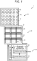
- Fig. 1 is a diagram illustrating an example of a schematic configuration of an image sensor 1 applied to each embodiment of the present disclosure.
- the image sensor 1 converts the received light into an electric signal and outputs it as a pixel signal.
- the image sensor 1 is configured as a CMOS image sensor.
- Fig. 1 illustrates an example of a schematic configuration of the image sensor 1 according to an embodiment of the present disclosure.
- the image sensor 1 includes three substrates (a first substrate 10, a second substrate 20, and a third substrate 30).
- the image sensor 1 is an image capturing device having a three-dimensional structure in which three substrates (first substrate 10, second substrate 20, and third substrate 30) are joined together.
- the first substrate 10, the second substrate 20, and the third substrate 30 are stacked in this order on top of each other.
- the first substrate 10 has a plurality of sensor pixels 12 that performs the photoelectric conversion.
- the sensor pixels 12 are disposed on a semiconductor substrate 11.
- the plurality of sensor pixels 12 is provided in a matrix in a pixel region 13 of the first substrate 10.
- the second substrate 20 has one readout circuit 22 for every four sensor pixels 12.
- the readout circuit 22 outputs a pixel signal based on the electric charge output from the sensor pixel 12 to a semiconductor substrate 303.
- the second substrate 20 has a plurality of pixel drive lines 23 extending in the row direction and a plurality of vertical signal lines 24 extending in the column direction.
- the third substrate 30 has a logic circuit 32 formed on a semiconductor substrate 31.
- the logic circuit 32 processes a pixel signal.
- the logic circuit 32 has, in one example, a vertical drive circuit 33, a column signal processing circuit 34, a horizontal drive circuit 35, and a system control circuit 36.
- the logic circuit 32 (specifically, the horizontal drive circuit 35 thereof) outputs the output voltage Vout for each sensor pixel 12 to the outside.
- the logic circuit 32 can have, in one example, a low-resistance region including a silicide prepared by performing a process using self-aligned silicide (salicide) such as CoSi 2 or NiSi, on the surface of the impurity diffusion region in contact with a source electrode and a drain electrode.
- silicide self-aligned silicide
- the vertical drive circuit 33 selects a plurality of sensor pixels 12, in one example, sequentially in row units.
- the column signal processing circuit 34 performs, in one example, correlated double sampling (CDS) processing on the pixel signal output from each sensor pixel 12 in the row selected by the vertical drive circuit 33.
- CDS correlated double sampling
- the column signal processing circuit 34 extracts, in one example, the signal level of the pixel signal by the CDS processing and holds pixel data corresponding to the amount of light received by each sensor pixel 12.
- the horizontal drive circuit 35 sequentially outputs, in one example, the pixel data held in the column signal processing circuit 34 to the outside.
- the system control circuit 36 controls, in one example, the driving of each block (i.e., the vertical drive circuit 33, the column signal processing circuit 34, and the horizontal drive circuit 35) in the logic circuit 32.
- Fig. 2 is a diagram illustrating an example of a sensor pixel 12 and a readout circuit 22. The description below is given of a case where the four sensor pixels 12 share one readout circuit 22 as illustrated in Fig. 2 .
- the term "share" used herein means that the outputs of the four sensor pixels 12 are input to the common readout circuit 22.
- the sensor pixels 12 each have a constituent component common to each other.
- an identification number i.e., 1, 2, 3, or 4
- the identification number is attached to the end of the reference numeral of the component of each sensor pixel 12.
- the identification number at the end of the reference numeral of the component of each sensor pixel 12 can be omitted.
- the sensor pixels 12 each have, in one example, a photodiode PD, a transfer transistor TR electrically connected to the photodiode PD, and a floating diffusion FD that temporarily holds the electric charge output from the photodiode PD via the transfer transistor TR.
- the photodiode PD corresponds to a specific implementation example of the "photoelectric transducer" of the present disclosure.
- the photodiode PD performs the photoelectric conversion to generate an electric charge corresponding to the amount of received light.
- the photodiode PD has the cathode electrically connected to the source of the transfer transistor TR and the anode electrically connected to the reference potential line (e.g., ground).
- the transfer transistor TR has the drain electrically connected to the floating diffusion FD and the gate electrically connected to the pixel drive line 23.
- the transfer transistor TR is, in one example, a complementary metal-oxide-semiconductor (CMOS) transistor.
- CMOS complementary metal-oxide-s
- the floating diffusion regions FDs of the sensor pixels 12 that share one readout circuit 22 are electrically connected to each other and are also electrically connected to the input terminal of the common readout circuit 22.
- the readout circuit 22 has, in one example, a reset transistor RST, a selection transistor SEL, and an amplification transistor AMP. Moreover, the selection transistor SEL can be omitted if necessary.
- the reset transistor RST has the source (the input terminal of the readout circuit 22) electrically connected to the floating diffusion FD and the drain electrically connected to a power supply line VDD and the drain of the amplification transistor AMP.
- the reset transistor RST has the gate electrically connected to the pixel drive line 23 (see Fig. 1 ).
- the amplification transistor AMP has the source electrically connected to the drain of the selection transistor SEL and the gate electrically connected to the source of the reset transistor RST.
- the selection transistor SEL (the output terminal of the readout circuit 22) has the source electrically connected to the vertical signal line 24 and the gate electrically connected to the pixel drive line 23 (see Fig. 1 ).
- the transfer transistor TR when turned on, transfers the electric charge of the photodiode PD to the floating diffusion FD.
- the reset transistor RST resets the potential of the floating diffusion FD to a predetermined potential.
- the reset transistor RST when turned on, resets the potential of the floating diffusion FD to the potential of the power supply line VDD.
- the selection transistor SEL controls the output timing of the pixel signal from the readout circuit 22.
- the amplification transistor AMP generates a voltage signal, as a pixel signal, corresponding to the level of electric charge held in the floating diffusion FD.
- the amplification transistor AMP constitutes a source follower amplifier and outputs a pixel signal with a voltage corresponding to the level of electric charge generated by the photodiode PD.
- the amplification transistor AMP amplifies the potential of the floating diffusion FD and outputs a voltage corresponding to the amplified potential to the column signal processing circuit 34 via the vertical signal line 24.
- the reset transistor RST, the amplification transistor AMP, and the selection transistor SEL are, in one example, CMOS transistors.
- Each pad electrode 58 is used for electrical connection between the second substrate 20 and the third substrate 30 and is used for joining the second substrate 20 and the third substrate 30 to each other.
- the plurality of pad electrodes 58 is provided, in one example, for each of the pixel drive line 23 and the vertical signal line 24 one by one.
- the total number of pad electrodes 58 (or the total number of joints between the pad electrodes 58 and the pad electrodes 64 (described later) is smaller than the total number of sensor pixels 12 included in the first substrate 10.
- a wiring extending in the vertical direction from the source region 222 (the output terminal side or FD) of each transfer transistor TR and a common wiring extending in the horizontal direction are formed as different materials, and they can be coupled to each other to constitute the wiring 301.
- the source region 222 (the output terminal side) of the transfer transistor TR corresponds to the "first element” provided for each photodiode PD among the plurality of elements formed on the first substrate 10.
- the gate electrode 311 (the gate) of the amplification transistor AMP corresponds to the "second element” to which a plurality of first elements is commonly connected.
- the wiring D1 is a wiring leading to the second element shared by the plurality of first elements and corresponds to the "first wiring” formed on the second substrate 20.
- the wiring D1 also corresponds to the "second wiring formed on the second substrate 20".
- the wiring 301 corresponds to the "second wiring", which is connected to the first wiring via one contact Ct and to which a plurality of first elements is connected.
- the wiring 301 is connected (indirectly connected) to the respective corresponding photodiodes PDs via the source region 222 of the transfer transistor TR.
- the wiring 301 is the "first wiring formed on the first substrate 10 and connected to the first photoelectric transducer and the second photoelectric transducer".
- connection used herein includes not only a form of being directly connected but also a form of being indirectly connected as described above.
- the wiring 301 is connected to the source region 222 of each transfer transistor TR.
- the wiring 301 is connected to a first floating diffusion region connected to the first transfer transistor and a second floating diffusion region connected to the second transfer transistor.
- the contact Ct corresponds to a "third wiring formed to penetrate the first substrate 10 and the second substrate 20 and connected to the first wiring and the second wiring".
- the third substrate 30 is configured by, in one example, stacking an interlayer insulating film 61 on the semiconductor substrate 31.
- the semiconductor substrate 31 is configured as a silicon substrate.
- the third substrate 30 has the logic circuit 32 provided on the front surface side of the semiconductor substrate 31.
- the third substrate 30 further has, in one example, a wiring layer 62 on the interlayer insulating film 61.
- the wiring layer 62 has, in one example, an insulating layer 63 and a plurality of pad electrodes 64 provided in the insulating layer 63.
- the plurality of pad electrodes 64 is electrically connected to the logic circuit 32.
- Each pad electrode 64 includes, for example, copper (Cu).
- Each pad electrode 64 is exposed on the front surface of the wiring layer 62.
- Each pad electrode 64 is used for electrical connection between the second substrate 20 and the third substrate 30 and is used for joining the second substrate 20 and the third substrate 30.
- the number of pad electrodes 64 is not necessarily plural, and even one pad electrode 64 can be electrically connected to the logic circuit 32.
- the second substrate 20 and the third substrate 30 are electrically connected to each other by joining the pad electrodes 58 and 64 mutually.
- the gate electrode 223 of the transfer transistor TR is electrically connected to the logic circuit 32 via the above-mentioned contact Ct and the pad electrodes 58 and 64.
- the third substrate 30 is joined to the second substrate 20 with the surface of the semiconductor substrate 31 facing the front surface side of the semiconductor substrate 303. In other words, the third substrate 30 is joined to the second substrate 20 in a face-to-face orientation.
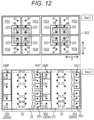
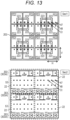
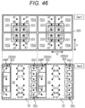
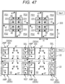
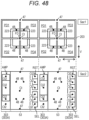
- Figs. 12 and 13 illustrate an example of the cross-sectional configuration in the horizontal direction of the image sensor 1.
- the upper views of Figs. 12 and 13 illustrate an example of the cross-sectional configuration of a cross-section Sec1 of Fig. 7
- the lower views of Figs. 12 and 13 illustrate the cross-sectional configuration of a cross-section Sec2 of Fig. 7 .
- Fig. 12 illustrates a configuration in which two sets of two-by-two, four sensor pixels 12 are arranged in a second direction V2.
- Fig. 13 illustrates a configuration in which four sets of two-by-two four sensor pixels 12 are arranged in a first direction V1 and the second direction V2.
- a view illustrating an example of the front surface configuration of the semiconductor substrate 11 is superimposed on a view illustrating an example of the cross-sectional configuration of the cross-section Sec1 of Fig. 7 , but the insulating layer 240 is omitted.
- a view illustrating an example of the front surface configuration of the semiconductor substrate 303 is superimposed on a view illustrating an example of the cross-sectional configuration of the cross-section Sec2 of Fig. 7 .
- the first direction V1 is parallel to one arrangement direction (e.g., column direction) of the two arrangement directions (e.g., row direction and column direction) of the plurality of sensor pixels 12 arranged in a matrix.
- the four floating diffusion regions FDs are arranged close to each other, in one example, through the pixel separation portion 203.
- the gate electrodes 223 of the four transfer transistors TRs are arranged to surround the four floating diffusion regions FDs. In one example, the four gate electrodes 223 form a ring shape.
- the insulating layer 53 which exists in the portion of the semiconductor substrate 303 mentioned above through which the contact Ct penetrates, includes a plurality of blocks extending in the first direction V1.
- the semiconductor substrate 303 extends in the first direction V1 and includes a plurality of island-shaped blocks 303A arranged side by side in the second direction V2 orthogonal to the first direction V1 via the insulating layer 53 described above.
- Each block 303A is provided with, in one example, a plurality of sets of reset transistors RSTs, amplification transistors AMPs, and selection transistors SELs.
- One readout circuit 22 shared by four sensor pixels 12 includes, in one example, the reset transistor RST, the amplification transistor AMP, and the selection transistor SEL in a region facing four sensor pixels 12.
- One readout circuit 22 shared by four sensor pixels 12 includes, in one example, the amplification transistor AMP in the block 303A to the immediate left of the insulating layer 53, and includes the reset transistor RST and the selection transistor SEL in the block 303A to the immediate right of the insulating layer 53.
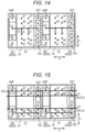
- the power supply line VDD is arranged, in one example, at a position facing each of the readout circuits 22 arranged side by side in the second direction V2, as illustrated in Fig. 15 .
- the power supply line VDD is electrically connected to the drain of the amplification transistor AMP and the drain of the reset transistor RST of each of the readout circuits 22 arranged side by side in the second direction V2 via the contact Ct2, in one example, as illustrated in Fig. 15 .
- the two pixel drive lines 23 are arranged, in one example, at a position facing each of the readout circuits 22 arranged side by side in the second direction V2, as illustrated in Fig. 15 .
- the vertical signal line 24 is arranged, in one example, at a position facing each readout circuit 22 arranged side by side in the first direction V1, as illustrated in Fig. 17 .
- the vertical signal line 24 (output line) is, in one example, electrically connected to the output terminal (source of the amplification transistor AMP) of each readout circuit 22 arranged side by side in the first direction V1, as illustrated in Fig. 17 .
- the semiconductor region and the pixel separation portion 203 are first formed in the first substrate 10 that is a silicon substrate, and the photodiode PD and the transfer transistor TR are provided for each pixel.
- the N-type drain region 221 and the N-type source region 222 are formed in the vicinity of the surface of the P-type semiconductor region (P-well) 204 partitioned by the pixel separation portion 203.
- the gate electrode 223 is formed between them. More specifically, an opening is defined between the N-type drain region 221 and the N-type source region 222 of the P-type semiconductor region 204. The opening leads to the photodiode PD (not illustrated in Fig.
- the gate electrode 223 is formed to fill the opening.
- the gate electrode 223 leads to a photodiode PD formed below the semiconductor region 204 (see Fig. 7 ).
- a region 205 illustrated in Fig. 7 indicates a region for one pixel partitioned by the pixel separation portion 203.
- an electrode 230 is formed on the P-type semiconductor region 204.
- the electrode 230 is used for leading the photodiode PD to the reference potential line to which the reference potential (e.g., ground) is supplied.
- the electrode 230 is provided for each pixel and leads to the photodiode PD (not illustrated).
- the transfer transistor TR is an N-channel type MOS transistor, and its drain region 221 is an N-type semiconductor region.
- the drain region 221 of the transfer transistor TR leads to the P-type semiconductor region 202 that covers the side surface of the photodiode PD.
- the terminal, which is not connected to the transfer transistor TR (input side terminal), of two terminals of the photodiode PD leads to the reference potential line.
- the photodiode PD is connected to the reference potential line via the electrode 230.
- the electrode 230 connected to the photodiode PD formed in the N-type semiconductor region is formed as P-type polysilicon.
- the N-type drain region 221, the N-type source region 222, the gate electrodes 223, and the electrode 230 are provided for each pixel in the P-type semiconductor region 204, and then they are covered with the insulating layer 240.
- the insulating layer 240 is configured as an oxide film such as SiO 2 .
- the insulating layer 240 is etched to form a wiring groove 241 and a wiring groove 242.
- the wiring groove 241 is used to form a wiring 301a that aggregates the source regions 222 of the plurality of transfer transistors TRs.
- the wiring groove 242 is used to form a wiring 301b that aggregates the plurality of electrodes 230.
- the wiring 301a and the wiring 301b are often referred herein to as simply "wiring 301" unless they are necessary to be distinguished.
- the source region 222 of the transfer transistor TR is an N-type semiconductor region, so the wiring 301a connected to the source region 222 is formed as P-type polysilicon.
- the electrode 230 is P-type polysilicon, so the wiring 301b connected to the electrode 230 is formed as N-type polysilicon.
- the wiring 301a that aggregates the output terminal sides of the plurality of transfer transistors TR is formed as P-type polysilicon.
- the electrode 230 connected to the photodiode PD formed in the N-type semiconductor region is formed as P-type polysilicon.
- the wiring 301b that aggregates the plurality of electrodes 230 is formed as N-type polysilicon.
- the P-type polysilicon which is a material for the wiring 301a
- the N-type polysilicon which is a material for the wiring 301b
- the resultant deposit is polished using chemical mechanical polishing (CMP) to form the wiring 301a and the wiring 301b (see Fig. 20 ).
- the wiring 301a is connected to the source regions 222 of four transfer transistors TRs having a one-to-one correspondence with the four photodiodes PDs.
- the wiring 301a aggregates the source regions 222 of the four transfer transistors TRs having a one-to-one correspondence with the four photodiodes PDs for each of the four photodiodes PDs.
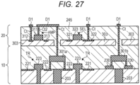
- the wiring 301a is connected to the wiring D1 via one contact Ct to connect the aggregated source region 222 to the wiring D1 of the second substrate 20 leading to the gate electrode 311 of the amplification transistor AMP shared by the source regions 222.
- one contact Ct is provided for every four source regions 222.
- the source regions 222 of the transfer transistor TR corresponds to the "first element”
- the gate electrode 311 of the amplification transistor AMP corresponds to the "second element”.
- the wiring D1 corresponds to the "first wiring” or the “second wiring formed on the second substrate”
- the wiring 301a corresponds to the "second wiring” or the "first wiring formed on the first substrate and connected to the first photoelectric transducer and the second photoelectric transducer".
- the number of pixels as a constituent unit for aggregation by the wiring 301a is not limited to four and can be optional.
- the wiring 301b is connected to four electrodes 230 having a one-to-one correspondence with the four photodiodes PDs.
- the wiring 301b aggregates four electrodes 230 having a one-to-one correspondence with the four photodiodes PDs.
- the wiring 301b is connected to the wiring D1 via one contact Ct to connect the aggregated electrodes 230 to the wiring D1 of the second substrate 20 leading to the reference potential line shared by the electrodes 230.
- one contact Ct is provided for every four electrodes 230.
- the wiring D1 leading to the reference potential line is different from the wiring D1 leading to the gate electrode 311 of the amplification transistor AMP described above (however, both are wirings formed on the insulating layer 245 of the second substrate 20).
- the electrode 230 corresponds to the "first element”
- the reference potential line corresponds to the "second element”.
- the wiring D1 corresponds to the "first wiring”
- the wiring 301b corresponds to the "second wiring”.
- the number of pixels as a constituent unit for aggregation by the wiring 301b is not limited to four and can be optional.
- the wirings 301b are connected (indirectly connected) to the respective corresponding photodiodes PDs via each electrode 230.
- the wiring 301b also corresponds to the "first wiring formed on the first substrate and connected to the first photoelectric transducer and the second photoelectric transducer".
- the wiring D1 also corresponds to the "second wiring formed on the second substrate”.
- the reference potential line is formed on the second substrate 20, but its configuration is not limited to the example above, and the reference potential line can be formed on, in one example, another substrate (such as the third substrate 30).
- the "second element" is not limited to an element formed on the second substrate 20.
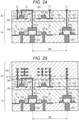
- the insulating layer 240 is deposited on the wiring 301a and the wiring 301b. Then, the P-type semiconductor substrate 303 is joined on top of the insulating layer 240 and is thinned.
- a portion of the semiconductor substrate 303 that faces the wiring 301 is opened to form a pixel transistor on the semiconductor substrate 303.
- the amplification transistor AMP and the selection transistor SEL are illustrated, but the reset transistor RST (not illustrated) is also formed on the semiconductor substrate 303.
- an N-type drain region 312 and an N-type source region 313 are formed in the vicinity of the surface of the semiconductor substrate 303.
- the gate electrode 311 is formed between them to form the amplification transistor AMP.
- an N-type drain region 321 and an N-type source region 322 are formed in the vicinity of the surface of the semiconductor substrate 303, a gate electrode 323 is formed between them to form the selection transistor SEL.
- the reset transistor RST (not illustrated) is also formed in a similar manner.
- the insulating layer 245 is formed (deposited) so that it covers the opening and the pixel transistor (such as amplification transistor AMP and selection transistor SEL) formed as described above.
- the contacts Ct and Ct2 are formed for connecting the wiring 301 and each element of the second substrate 20 to the wiring D1.
- the contact Ct is provided for each of the drain region 312 of the amplification transistor AMP, the wiring 301, and the source region 322 of the selection transistor SEL.
- the contact Ct2 is provided for the gate electrode 311 of the amplification transistor AMP.
- a way is considered of etching the insulating layer to form an opening defining the contacts Ct and Ct2, forming a barrier layer for electrically insulating on the inner surface of the opening, then filling it with a material of the contacts Ct and Ct2.
- the insulating layer (the insulating layer covering the side surface of the contact Ct) provided at the opening of the semiconductor substrate 303 is the insulating layer 53 described above.
- Examples of the material of the contacts Ct and Ct2 include tungsten or the like.
- the barrier layer includes, in one example, Ti, TiN, Ta, TaN, or the like as material.
- the method of forming the contacts Ct and Ct2 and their materials are not limited to the example above and are optional, and various known techniques can be employed.
- the wiring layer 246 described above is formed on the insulating layer 245.
- the third substrate 30 on which the peripheral circuit is formed is joined to form a color filter and an on-chip lens for each pixel.
- the configuration illustrated in Fig. 7 can be obtained.
- a region 270 indicates a set of connection points 271 between the electrodes 230 and the wiring 301b for each of the four electrodes 230 having a one-to-one correspondence with four photodiodes PDs as a constituent unit of sharing the reference potential line.
- first substrate 10 and the second substrate 20 separated from each other make it possible to increase the number of pixels per unit area, as compared with the configuration in which the photodiode PD and the pixel transistor are provided on the same substrate, improving the resolution.
- the lens unit 11401 is an optical system, provided at a connecting location to the lens barrel 11101. Observation light taken in from a distal end of the lens barrel 11101 is guided to the camera head 11102 and introduced into the lens unit 11401.
- the lens unit 11401 includes a combination of a plurality of lenses including a zoom lens and a focusing lens.
- the communication unit 11404 includes a communication apparatus for transmitting and receiving various kinds of information to and from the CCU 11201.
- the communication unit 11404 transmits an image signal acquired from the imaging unit 11402 as RAW data to the CCU 11201 through the transmission cable 11400.
- the communication unit 11411 transmits a control signal for controlling driving of the camera head 11102 to the camera head 11102.
- the image signal and the control signal can be transmitted by electrical communication, optical communication or the like.
- the description above is given of an example of the endoscopic surgery system to which the technology according to the present disclosure is applicable.
- the technology according to the present disclosure is suitably applicable to the imaging unit 11402 provided on the camera head 11102 of the endoscope 11100 in the configuration described above.
- the technology according to the present disclosure applied to the imaging unit 11402 makes it possible to reduce the size of the imaging unit 11402 or achieve high-definition image capturing unit. Thus, it is possible to provide a small-sized or high-definition endoscope 11100.
- present technology may also be configured as below.
Landscapes
- Engineering & Computer Science (AREA)
- Multimedia (AREA)
- Signal Processing (AREA)
- Solid State Image Pick-Up Elements (AREA)
- Transforming Light Signals Into Electric Signals (AREA)
- Internal Circuitry In Semiconductor Integrated Circuit Devices (AREA)
- Metal-Oxide And Bipolar Metal-Oxide Semiconductor Integrated Circuits (AREA)
Abstract
Description
- The present disclosure relates to an image sensor and an electronic apparatus, such as a camera, provided with the image sensor.
- In an image capturing device such as complementary metal-oxide-semiconductor (CMOS), in one example, a configuration in which a first semiconductor substrate having a pixel region and a second semiconductor substrate having a logic circuit are stacked on top of each other is known (e.g., refer to
Patent Document 1 or other related arts). - Patent Document 1:
JP 2010-245506 A - The image capturing device disclosed in
Patent Document 1 has a photoelectric transducer and a pixel transistor, both disposed on the same semiconductor substrate. The pixel transistor reads out an electric signal corresponding to the amount of light received by the photoelectric transducer. However, such a configuration fails to reduce the area of the substrate (the space of the substrate's surface on which circuit components such as transistors are formed) satisfactorily. - Thus, in one example, it is conceivable to stack individually the substrate on which the photoelectric transducer is formed (first substrate) and the substrate on which the pixel transistor is formed (second substrate) on top of each other. In such a configuration, in one example, it is assumed that a plurality of photoelectric transducers having a one-to-one correspondence with a plurality of pixels shares one pixel transistor. In this case, among elements (e.g., circuit components such as transistors) disposed on the first substrate, a plurality of first elements provided for respective corresponding photoelectric transducers is commonly connected to a second element to be a shared element.
- The configuration described above is necessary to connect the plurality of first elements on the first substrate to the wiring that leads to the second element shared by the first elements and formed on the second substrate, using a contact one by one. This will increase the number of contacts for the wiring, causing the area to be large.
- The present disclosure is intended to provide an image sensor and an electronic apparatus capable of reducing the substrate mounting area.
- In order to achieve the above-mentioned object, an image sensor according to the present disclosure is an image sensor including a first substrate having a plurality of photoelectric transducers formed on the first substrate, a second substrate having a pixel transistor for each of sets of two or more of the photoelectric transducers as a constituent unit, the pixel transistor being shared by the set and formed on the second substrate, and a second wiring which is connected to a first wiring formed on the second substrate via one contact, and is connected to a plurality of first elements, the first wiring leading to a second element shared by a plurality of first elements among a plurality of elements formed on the first substrate, each of the plurality of first elements being formed for each of the photoelectric transducers.
- The term "element" used herein is a concept that includes the entirety or a part of circuit components, such as photoelectric transducers, transistors, and wirings (including electrodes), formed on a substrate (a semiconductor substrate). In addition, the term "pixel transistor" is a transistor that is used to read out an electric signal corresponding to the amount of light received by the photoelectric transducer and can be shared by a plurality of photoelectric transducers (pixels). In one example, the pixel transistor includes at least an amplification transistor that amplifies and outputs an electric signal supplied from the photoelectric transducer.
- (Mode of operation) The image sensor of the present disclosure is provided with the first wiring and the second wiring. The first wiring formed on the second substrate leads to the second element shared by the plurality of first elements on the first substrate. The second wiring is connected to the first wiring via one contact and is connected to the plurality of first elements. In other words, the second wiring aggregates a plurality of first elements and is connected, via one contact, to the wiring leading to the second element shared (commonly connected) by the plurality of first elements. This makes it sufficient to set the number of contacts formed in the first wiring for connecting the plurality of first elements as a constituent unit for aggregation to the first wiring to one. Thus, it is possible to reduce the number of contacts and the area of the first wiring.
- Further, the image sensor of the present disclosure has the first substrate on which the photoelectric transducer is formed and the second substrate on which the pixel transistor is formed. The first substrate and the second substrate are individually stacked on top of each other. Thus, it is possible to reduce the substrate's area.
- According to the present disclosure, it is possible to reduce the substrate's area. Note that the advantageous effects described here are not necessarily limitative, and any of the advantageous effects described in the present disclosure may be attained.
-
-
Fig. 1 is a diagram illustrating an example of a schematic configuration of an image sensor applied to each embodiment of the present disclosure. -
Fig. 2 is a diagram illustrating an example of a sensor pixel and a readout circuit ofFig. 1 . -
Fig. 3 is a diagram illustrating an example of a sensor pixel and a readout circuit ofFig. 1 . -
Fig. 4 is a diagram illustrating an example of a sensor pixel and a readout circuit ofFig. 1 . -
Fig. 5 is a diagram illustrating an example of a sensor pixel and a readout circuit ofFig. 1 . -
Fig. 6 is a diagram illustrating an example of a connection mode between a plurality of readout circuits and a plurality of vertical signal lines. -
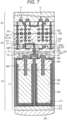
Fig. 7 is a diagram illustrating an example of a cross-sectional configuration in the vertical direction of the image sensor ofFig. 1 . -
Fig. 8 is a diagram illustrating a modification of an N-type semiconductor region that constitutes a photodiode of a first embodiment. -
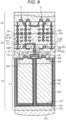
Fig. 9 is a diagram illustrating a modification of the structure of the image sensor of the first embodiment. -
Fig. 10 is a diagram illustrating the arrangement of a joint point between a second substrate and a third substrate. -
Fig. 11 is a diagram illustrating a modification of arrangement of joint points between the second substrate and the third substrate. -
Fig. 12 is a diagram illustrating an example of a cross-sectional configuration in the horizontal direction of the image sensor ofFig. 1 . -
Fig. 13 is a diagram illustrating an example of a cross-sectional configuration in the horizontal direction of the image sensor ofFig. 1 . -
Fig. 14 is a diagram illustrating an example of a wiring layout in a horizontal plane of the image sensor ofFig. 1 . -
Fig. 15 is a diagram illustrating an example of a wiring layout in a horizontal plane of the image sensor ofFig. 1 . -
Fig. 16 is a diagram illustrating an example of a wiring layout in a horizontal plane of the image sensor ofFig. 1 . -
Fig. 17 is a diagram illustrating an example of a wiring layout in a horizontal plane of the image sensor ofFig. 1 . -
Fig. 18 is a diagram illustrated to describe an example of a method of manufacturing the image sensor of the first embodiment. -
Fig. 19 is a diagram illustrated to describe an example of a method of manufacturing the image sensor of the first embodiment. -
Fig. 20 is a diagram illustrated to describe an example of a method of manufacturing the image sensor of the first embodiment. -
Fig. 21 is a diagram illustrated to describe an example of a method of manufacturing the image sensor of the first embodiment. -
Fig. 22 is a diagram illustrated to describe an example of a method of manufacturing the image sensor of the first embodiment. -
Fig. 23 is a diagram illustrated to describe an example of a method of manufacturing the image sensor of the first embodiment. -
Fig. 24 is a diagram illustrated to describe an example of a method of manufacturing the image sensor of the first embodiment. -
Fig. 25 is a diagram illustrated to describe an example of a method of manufacturing the image sensor of the first embodiment. -
Fig. 26 is a diagram illustrating a part of a cross-section of an image sensor upon employing a configuration in which a wiring is not provided. -
Fig. 27 is a diagram illustrating a part of a cross-section of the image sensor of the first embodiment. -
Fig. 28 is a schematic plan view of the first substrate of the first embodiment. -
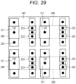
Fig. 29 is a schematic plan view of the second substrate of the first embodiment. -
Fig. 30 is a schematic plan view of the arrangement in which the second substrate and the first substrate are arranged on top of each other according to the first embodiment. -
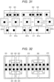
Fig. 31 is a diagram illustrating a modification of a wiring layout. -
Fig. 32 is a schematic plan view of a first substrate according to a modification of the first embodiment. -
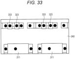
Fig. 33 is a schematic plan view of a second substrate according to a modification of the first embodiment. -
Fig. 34 is a diagram illustrating a part of a cross-section of the image sensor of a fourth embodiment. -
Fig. 35 is a diagram illustrating a part of a cross-section of the image sensor of a fifth embodiment. -
Fig. 36 is a diagram illustrating a part of a cross-section of the image sensor of a sixth embodiment. -
Fig. 37 is a diagram illustrating a part of a cross-section of an image sensor according to a modification of the sixth embodiment. -
Fig. 38 is a diagram illustrating a configuration example of a camera that is an example of an electronic apparatus to which the image sensor of the present disclosure is applied. -
Fig. 39 is a diagram illustrating an example of the sensor pixel and the readout circuit ofFig. 1 . -
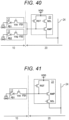
Fig. 40 is a diagram illustrating an example of the sensor pixel and the readout circuit ofFig. 1 . -
Fig. 41 is a diagram illustrating an example of the sensor pixel and the readout circuit ofFig. 1 . -
Fig. 42 is a diagram illustrating an example of the sensor pixel and the readout circuit ofFig. 1 . -
Fig. 43 is a diagram illustrating an example of a cross-sectional configuration in the vertical direction of the image sensor ofFig. 1 . -
Fig. 44 is a diagram illustrating an example of a cross-sectional configuration in the horizontal direction of the image sensor ofFig. 1 . -
Fig. 45 is a diagram illustrating an example of a cross-sectional configuration in the horizontal direction of the image sensor ofFig. 1 . -
Fig. 46 is a diagram illustrating an example of a cross-sectional configuration in the horizontal direction of the image sensor ofFig. 1 . -
Fig. 47 is a diagram illustrating an example of a cross-sectional configuration in the horizontal direction of the image sensor ofFig. 1 . -
Fig. 48 is a diagram illustrating an example of a cross-sectional configuration in the horizontal direction of the image sensor ofFig. 1 . -
Fig. 49 is a diagram illustrating an example of a cross-sectional configuration in the horizontal direction of the image sensor ofFig. 1 . -
Fig. 50 is a diagram illustrating an example of a cross-sectional configuration in the horizontal direction of the image sensor ofFig. 1 . -
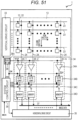
Fig. 51 is a diagram illustrating an example of a circuit configuration of an image capturing device that includes an image capturing device according to the embodiments described above and their modifications. -
Fig. 52 is a diagram illustrating an example in which the image sensor ofFig. 51 is configured by stacking three substrates on top of each other. -
Fig. 53 is a diagram illustrating an example in which a logic circuit is individually formed on a substrate provided with a sensor pixel and on a substrate provided with a readout circuit. -
Fig. 54 is a diagram illustrating an example in which a logic circuit is formed on a third substrate. -
Fig. 55 is a diagram illustrating an example of a schematic configuration of an image capturing system having the image sensor. -
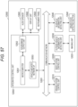
Fig. 56 is a diagram illustrating an example of an image capturing procedure in the image capturing system ofFig. 55 . -
Fig. 57 is a block diagram depicting an example of schematic configuration of a vehicle control system. -
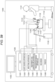
Fig. 58 is a diagram of assistance in explaining an example of installation positions of an outside-vehicle information detecting section and an imaging unit. -
Fig. 59 is a view depicting an example of a schematic configuration of an endoscopic surgery system. -
Fig. 60 is a block diagram depicting an example of a functional configuration of the camera head and the CCU. - An example of an image sensor and an electronic apparatus according to an embodiment of the present disclosure is now described in detail with reference to the attached drawings. The description is given in the order below.
- 1. Schematic configuration example of image sensor
- 2. First embodiment (configuration example of image sensor)
- 3. Second embodiment (configuration example of image sensor)
- 4. Third embodiment (configuration example of image sensor)
- 5. Fourth embodiment (configuration example of image sensor)
- 6. Fifth embodiment (configuration example of image sensor)
- 7. Sixth embodiment (configuration example of image sensor)
- 8. Seventh embodiment (configuration example of electronic apparatus)
- 9. Modification
- 10. Application example
- 11. Usage example
-
Fig. 1 is a diagram illustrating an example of a schematic configuration of animage sensor 1 applied to each embodiment of the present disclosure. Theimage sensor 1 converts the received light into an electric signal and outputs it as a pixel signal. In this example, theimage sensor 1 is configured as a CMOS image sensor. -
Fig. 1 illustrates an example of a schematic configuration of theimage sensor 1 according to an embodiment of the present disclosure. Theimage sensor 1 includes three substrates (afirst substrate 10, asecond substrate 20, and a third substrate 30). Theimage sensor 1 is an image capturing device having a three-dimensional structure in which three substrates (first substrate 10,second substrate 20, and third substrate 30) are joined together. Thefirst substrate 10, thesecond substrate 20, and thethird substrate 30 are stacked in this order on top of each other. - The
first substrate 10 has a plurality ofsensor pixels 12 that performs the photoelectric conversion. Thesensor pixels 12 are disposed on asemiconductor substrate 11. The plurality ofsensor pixels 12 is provided in a matrix in apixel region 13 of thefirst substrate 10. Thesecond substrate 20 has onereadout circuit 22 for every foursensor pixels 12. Thereadout circuit 22 outputs a pixel signal based on the electric charge output from thesensor pixel 12 to asemiconductor substrate 303. Thesecond substrate 20 has a plurality ofpixel drive lines 23 extending in the row direction and a plurality ofvertical signal lines 24 extending in the column direction. Thethird substrate 30 has alogic circuit 32 formed on asemiconductor substrate 31. Thelogic circuit 32 processes a pixel signal. Thelogic circuit 32 has, in one example, avertical drive circuit 33, a columnsignal processing circuit 34, ahorizontal drive circuit 35, and asystem control circuit 36. The logic circuit 32 (specifically, thehorizontal drive circuit 35 thereof) outputs the output voltage Vout for eachsensor pixel 12 to the outside. Thelogic circuit 32 can have, in one example, a low-resistance region including a silicide prepared by performing a process using self-aligned silicide (salicide) such as CoSi2 or NiSi, on the surface of the impurity diffusion region in contact with a source electrode and a drain electrode. - The
vertical drive circuit 33 selects a plurality ofsensor pixels 12, in one example, sequentially in row units. The columnsignal processing circuit 34 performs, in one example, correlated double sampling (CDS) processing on the pixel signal output from eachsensor pixel 12 in the row selected by thevertical drive circuit 33. The columnsignal processing circuit 34 extracts, in one example, the signal level of the pixel signal by the CDS processing and holds pixel data corresponding to the amount of light received by eachsensor pixel 12. Thehorizontal drive circuit 35 sequentially outputs, in one example, the pixel data held in the columnsignal processing circuit 34 to the outside. Thesystem control circuit 36 controls, in one example, the driving of each block (i.e., thevertical drive circuit 33, the columnsignal processing circuit 34, and the horizontal drive circuit 35) in thelogic circuit 32. -
Fig. 2 is a diagram illustrating an example of asensor pixel 12 and areadout circuit 22. The description below is given of a case where the foursensor pixels 12 share onereadout circuit 22 as illustrated inFig. 2 . The term "share" used herein means that the outputs of the foursensor pixels 12 are input to thecommon readout circuit 22. - The
sensor pixels 12 each have a constituent component common to each other. InFig. 2 , an identification number (i.e., 1, 2, 3, or 4) is attached to the end of the reference numeral denoting the component of eachsensor pixel 12 to distinguish the components of eachsensor pixel 12 from each other. In the case where it is necessary to distinguish the components of eachsensor pixel 12 from each other, the identification number is attached to the end of the reference numeral of the component of eachsensor pixel 12. However, in the case where it is not necessary to distinguish the components of eachsensor pixel 12 from each other, the identification number at the end of the reference numeral of the component of eachsensor pixel 12 can be omitted. - The
sensor pixels 12 each have, in one example, a photodiode PD, a transfer transistor TR electrically connected to the photodiode PD, and a floating diffusion FD that temporarily holds the electric charge output from the photodiode PD via the transfer transistor TR. The photodiode PD corresponds to a specific implementation example of the "photoelectric transducer" of the present disclosure. The photodiode PD performs the photoelectric conversion to generate an electric charge corresponding to the amount of received light. The photodiode PD has the cathode electrically connected to the source of the transfer transistor TR and the anode electrically connected to the reference potential line (e.g., ground). The transfer transistor TR has the drain electrically connected to the floating diffusion FD and the gate electrically connected to thepixel drive line 23. The transfer transistor TR is, in one example, a complementary metal-oxide-semiconductor (CMOS) transistor. - The floating diffusion regions FDs of the
sensor pixels 12 that share onereadout circuit 22 are electrically connected to each other and are also electrically connected to the input terminal of thecommon readout circuit 22. Thereadout circuit 22 has, in one example, a reset transistor RST, a selection transistor SEL, and an amplification transistor AMP. Moreover, the selection transistor SEL can be omitted if necessary. The reset transistor RST has the source (the input terminal of the readout circuit 22) electrically connected to the floating diffusion FD and the drain electrically connected to a power supply line VDD and the drain of the amplification transistor AMP. The reset transistor RST has the gate electrically connected to the pixel drive line 23 (seeFig. 1 ). The amplification transistor AMP has the source electrically connected to the drain of the selection transistor SEL and the gate electrically connected to the source of the reset transistor RST. The selection transistor SEL (the output terminal of the readout circuit 22) has the source electrically connected to thevertical signal line 24 and the gate electrically connected to the pixel drive line 23 (seeFig. 1 ). - The transfer transistor TR, when turned on, transfers the electric charge of the photodiode PD to the floating diffusion FD. The reset transistor RST resets the potential of the floating diffusion FD to a predetermined potential. The reset transistor RST, when turned on, resets the potential of the floating diffusion FD to the potential of the power supply line VDD. The selection transistor SEL controls the output timing of the pixel signal from the
readout circuit 22. The amplification transistor AMP generates a voltage signal, as a pixel signal, corresponding to the level of electric charge held in the floating diffusion FD. The amplification transistor AMP constitutes a source follower amplifier and outputs a pixel signal with a voltage corresponding to the level of electric charge generated by the photodiode PD. In the case where the selection transistor SEL is turned on, the amplification transistor AMP amplifies the potential of the floating diffusion FD and outputs a voltage corresponding to the amplified potential to the columnsignal processing circuit 34 via thevertical signal line 24. The reset transistor RST, the amplification transistor AMP, and the selection transistor SEL are, in one example, CMOS transistors. - As described above, for each constituent unit in which four
sensor pixels 12 share one readout circuit 22 (can be referred to hereinafter as "shared constituent unit" or "shared constituent unit circuit"), four photoelectric transducer PDs, four transfer transistors TRs, one amplification transistor AMP, one reset transistor RST, and one selection transistor SEL are included. The transfer transistors TRs have a one-to-one correspondence with the photoelectric transducer PDs. In this example, four pixels (thesensor pixels 12 including at least the photoelectric transducer PD) share a combination of one amplification transistor AMP, one reset transistor RST, and one selection transistor SEL. In this example, the combination of one amplification transistor AMP, one reset transistor RST, and one selection transistor SEL corresponds to a "pixel transistor". - Further, as described above, a plurality of photodiodes PDs having a one-to-one correspondence with a plurality of pixels is formed on the
first substrate 10 that corresponds to the "first substrate" of the present disclosure. More specifically, the transfer transistor TR used for transferring an electric signal output from the photodiode PD to the pixel transistor is also formed on thefirst substrate 10 for each of the plurality of photodiode PDs. In this description, two photodiode PDs, that are included in the plurality of photodiode PDs formed on thefirst substrate 10, correspond to the "first photoelectric transducer" and the "second photoelectric transducer", respectively. Then, the transfer transistor TR connected to the photodiode PD corresponding to the first photoelectric transducer corresponds to the "first transfer transistor", and the transfer transistor TR connected to the photodiode PD corresponding to the second photoelectric transducer corresponds to the "second transfer transistor". In other words, the first photoelectric transducer and the second photoelectric transducer are formed on thefirst substrate 10. Thus, it can be considered that thefirst substrate 10 has the first transfer transistor connected to the first photoelectric transducer and the second transfer transistor connected to the second photoelectric transducer. - Further, for each set of two or more (four in this example) photodiodes PDs as a constituent unit, the pixel transistor shared by the set is formed on the
second substrate 20 corresponding to the "second substrate" of the present disclosure. More specifically, the pixel transistor, which includes at least one amplification transistor AMP that amplifies and outputs an electric signal transferred from each of the two or more transfer transistors TR included in the set, is formed on thesecond substrate 20 for each one or more sets. In this description, it can be considered that the pixel transistor connected to the first photoelectric transducer and the second photoelectric transducer is formed on the second substrate. - Moreover, as illustrated in
Fig. 3 , the selection transistor SEL can be provided between the power supply line VDD and the amplification transistor AMP. In this case, the drain of the reset transistor RST is electrically connected to the drain of the power supply line VDD and the selection transistor SEL. The source of the selection transistor SEL is electrically connected to the drain of the amplification transistor AMP, and the gate of the selection transistor SEL is electrically connected to the pixel drive line 23 (seeFig. 1 ). The source of the amplification transistor AMP (the output terminal of the readout circuit 22) is electrically connected to thevertical signal line 24, and the gate of the amplification transistor AMP is electrically connected to the source of the reset transistor RST. In addition, as illustrated inFigs. 4 and 5 , an FD transfer transistor FDG can be provided between the source of the reset transistor RST and the gate of the amplification transistor AMP. - The FD transfer transistor FDG is used for switching the conversion efficiency. The pixel signal is generally small upon shooting at a dark place. If the capacitance of the floating diffusion FD (FD capacitance C) is large in performing the charge-to-voltage conversion on the basis of the formula Q = CV, the V upon the conversion to the voltage by the amplification transistor AMP will be small. On the other hand, at a bright place, the pixel signal is large, so unless the FD capacitance C is large, the floating diffusion FD fails to receive the electric charge of the photodiode PD. Furthermore, the FD capacitance C is necessary to be large so that V upon the conversion to a voltage by the amplification transistor AMP does not become too large (in other words, to keep it small). In consideration of this fact, in the case where the FD transfer transistor FDG is turned on, the gate capacitance of the FD transfer transistor FDG increases, so the total FD capacitance C increases. On the other hand, in the case where the FD transfer transistor FDG is turned off, the total FD capacitance C is smaller. Thus, the on/off switching of the FD transfer transistor FDG makes the FD capacitance C variable, enabling the conversion efficiency to be switched.
-
Fig. 6 is a diagram illustrating an example of a connection mode between a plurality ofreadout circuits 22 and a plurality of vertical signal lines 24. In the case where the plurality ofreadout circuits 22 is arranged side by side in the extending direction (e.g., the column direction) of thevertical signal lines 24, the plurality ofvertical signal lines 24 can be assigned individually to thereadout circuits 22. In one example, in the case where the fourreadout circuits 22 are arranged side by side in the extending direction (e.g., the column direction) of thevertical signal lines 24 as illustrated inFig. 6 , fourvertical signal lines 24 can be assigned to the individualcorresponding readout circuits 22. Moreover, inFig. 6 , to distinguish eachvertical signal line 24, an identification number (1, 2, 3, or 4) is attached to the end of the reference numeral of eachvertical signal line 24. - The configuration of the
image sensor 1 according to the first embodiment is now described together with a method of manufacturing the same. -
Fig. 7 is a diagram illustrating a part of a cross-section corresponding to one shared constituent unit circuit of theimage sensor 1 according to the present embodiment. As illustrated inFig. 7 , theimage sensor 1 includes thefirst substrate 10, thesecond substrate 20, and thethird substrate 30, which are stacked on top of each other and electrically connected. Thethird substrate 30 has a peripheral circuit formed thereon. In this example, the peripheral circuit includes thelogic circuit 32 having thevertical drive circuit 33, the columnsignal processing circuit 34, thehorizontal drive circuit 35, and thesystem control circuit 36. The peripheral circuit is formed on thethird substrate 30. Besides, in one example, the entirety or a part of the elements (such as thevertical drive circuit 33, the columnsignal processing circuit 34, thehorizontal drive circuit 35, and the system control circuit 36) included in the peripheral circuit can be formed on thefirst substrate 10 or thesecond substrate 20. In this example, thethird substrate 30 includes at least thelogic circuit 32. Thelogic circuit 32 corresponds to a "logic circuit formed on the second substrate for processing a signal generated by the first photoelectric transducer or the second photoelectric transducer". Thethird substrate 30 corresponds to the "third substrate" of the present disclosure. Moreover, asurface 501 illustrated inFig. 7 indicates a surface on which thefirst substrate 10 and thesecond substrate 20 are joined together. In addition, asurface 502 illustrated inFig. 7 indicates a surface on which thesecond substrate 20 and thethird substrate 30 are joined together. - The
image sensor 1 according to the present embodiment includes a first wiring and a second wiring. The first wiring is formed on thesecond substrate 20 and leads to a second element shared by a plurality of first elements provided for each photodiode PD among the plurality of elements formed on thefirst substrate 10. The second wiring is connected to the first wiring via one contact. The plurality of first elements is connected to the second wiring. In the example ofFig. 7 , theimage sensor 1 is provided with a wiring 301 ("second wiring") that connects the output terminal side ("first element") of the plurality of transfer transistors TRs to a wiring D1 ("first wiring") formed on thesecond substrate 20 via one contact. The wiring D1 leads to the gate ("second element") of the amplification transistor AMP shared (commonly connected) by the output terminal side of the plurality of transfer transistors TRs. Details thereof will be described later. - The configuration of the
image sensor 1 illustrated inFig. 7 is now described. As illustrated inFig. 7 , thefirst substrate 10 is configured by stacking an insulatinglayer 240 on top of thesemiconductor substrate 11. Thefirst substrate 10 has the insulatinglayer 240 as a part of aninterlayer insulating film 51. The insulatinglayer 240 is provided in a gap between thesemiconductor substrate 11 and thesemiconductor substrate 303 described later. Thesemiconductor substrate 11 is configured as a silicon substrate. Thesemiconductor substrate 11 has, in one example, a P-type semiconductor region 204 (P-well) in a part of the surface or the vicinity thereof and has a conductive (N-type) photodiode PD different from the P-type semiconductor region 204 in other regions (regions deeper than the P-type semiconductor region 204). - The plurality of photodiode PDs is formed on the
first substrate 10. In addition, a plurality of transfer transistors TRs having a one-to-one correspondence with the plurality of photodiode PDs is formed on thefirst substrate 10. In the example ofFig. 7 , the photodiode PD is formed in the N-type semiconductor region, and a P-type semiconductor region 202 different from the photodiode PD is formed to cover the side surface thereof. The photodiodes PDs are electrically separated from each other by apixel separation portion 203 used for separating (dividing) pixels. In one example, thepixel separation portion 203 includes a metal, an insulating film (e.g., SiO2), a combination thereof, or the like. - On the lower surface of the photodiode PD, an insulating
film 211 is formed to cover thefirst substrate 10. The insulatingfilm 211 includes, in one example, a film having a fixed electric charge or the like. An additional insulating film as aplanarization film 213 can be formed between the insulatingfilm 211 and acolor filter 212. The insulatingfilm 211 includes a metal oxide film such as hafnium oxide, tantalum oxide, or aluminum oxide. Theplanarization film 213 includes an insulating film such as silicon oxide or silicon nitride. Moreover, the insulatingfilm 211 and theplanarization film 213 each can be provided in the form of a plurality of layers. An on-chip lens 214 is formed under thecolor filter 212. The on-chip lens 214 condenses the irradiated light, and the condensed light is guided to the photodiode PD through thecolor filter 212. - Further, an N-type transfer transistor TR is formed on the photodiode PD. More specifically, the P-type semiconductor region 204 (P-well) is formed on the photodiode PD in the
first substrate 10, and an N-type drain region 221 and an N-type source region 222 are formed in the vicinity of the surface of thesemiconductor region 204. Then, agate electrode 223 is formed between the N-type drain region 221 and the N-type source region 222 on thesemiconductor region 204. In this example, thegate electrode 223 leads to the photodiode PD. In addition, in this example, the P-type semiconductor region 202 covering the side surface of the photodiode PD protrudes to cover a part of the side surface of thesemiconductor region 204, but its configuration is not limited to the example above. The P-type semiconductor region 202 can have any depth. In one example, the upper surface of thesemiconductor region 202 can be flush with the lower surface of thesemiconductor region 204. - Further, the photodiode PD can have any depth, and in one example, as illustrated in
Fig. 8 , a part of the photodiode PD reaches the same height as the surface of the P-type semiconductor region 204 on which the transfer transistor TR is formed. In such a case, the P-type semiconductor region is preferably formed on the N-type photodiode PD, but its arrangement can be a form rather than the configuration illustrated inFig. 8 . Furthermore, in one example, as illustrated inFig. 9 , thegate electrode 223 of the transfer transistor TR can be formed on thesemiconductor region 204 without leading to the photodiode PD. In other words, the transfer transistor TR can have a planar transfer gate (the gate electrode 223). - The description continues referring back to
Fig. 7 . As illustrated inFig. 7 , thesource region 222 of each transfer transistor TR is connected to thewiring 301. In this example, thesource region 222 is an N-type semiconductor region, so thewiring 301 is formed as P-type polysilicon. Each transfer transistor TR and thewiring 301 are covered with the insulatinglayer 240, and thesemiconductor substrate 303 is formed on the insulatinglayer 240. - Moreover, it can be considered that the combination of the
semiconductor substrate 303 and each element formed on thesemiconductor substrate 303 corresponds to the "second substrate" of the present disclosure, or it can also be considered that only thesemiconductor substrate 303 corresponds to the "second substrate" of the present disclosure. Similarly, for thefirst substrate 10, it can be considered that the combination of a base silicon substrate and each element formed on the silicon substrate corresponds to the "first substrate" of the present disclosure, or it can also be considered that only the silicon substrate corresponds to the "first substrate" of the present disclosure. - As described above, the
second substrate 20 has a pixel transistor formed thereon. The pixel transistor includes at least the amplification transistor AMP. In this example, each transistor included in the pixel transistor is an N-channel MOS transistor, and thesemiconductor substrate 303 is a P-type silicon substrate. - The
wiring 301 is connected to the wiring D1 formed on thesecond substrate 20 via a contact Ct penetrating thesemiconductor substrate 303. In this example, thesecond substrate 20 is configured by stacking an insulatinglayer 245 on top of thesemiconductor substrate 303. Thesecond substrate 20 has the insulatinglayer 245 as a part of theinterlayer insulating film 51. The insulatinglayer 245 is provided in the gap between thesemiconductor substrate 303 and thesemiconductor substrate 31 described later. Thesecond substrate 20 has onereadout circuit 22 for every foursensor pixels 12. Thesecond substrate 20 has the arrangement in which thereadout circuit 22 is provided on the surface side (the side of the third substrate 30) of thesemiconductor substrate 303. Thesecond substrate 20 is joined to thefirst substrate 10 with the back surface of thesemiconductor substrate 303 facing the front surface side of thesemiconductor substrate 11. In other words, thesecond substrate 20 is joined to thefirst substrate 10 in a face-to-back orientation. Thesecond substrate 20 further has an insulatinglayer 53 penetrating thesemiconductor substrate 303 in the same layer as thesemiconductor substrate 303. Thesecond substrate 20 has the insulatinglayer 53 as a part of theinterlayer insulating film 51. The insulatinglayer 53 is provided to cover the side surface of the contact Ct penetrating thesemiconductor substrate 303. - The stacked structure having the
first substrate 10 and thesecond substrate 20 has one contact Ct for eachsensor pixel 12. Thefirst substrate 10 and thesecond substrate 20 are electrically connected to each other via the contact Ct. Specifically, the contact Ct is electrically connected to the floating diffusion FD and the wiring D1 described later. - The stacked structure having the
first substrate 10 and thesecond substrate 20 further has through wirings 47 and 48 (seeFig. 12 or the like described later) provided in theinterlayer insulating film 51. The stacked structure has one throughwiring 47 and one throughwiring 48 for eachsensor pixel 12. The throughwirings semiconductor substrate 303 and are provided to penetrate thesemiconductor substrate 303. Thefirst substrate 10 and thesecond substrate 20 are electrically connected to each other with the throughwirings wiring 47 is electrically connected to the P-type semiconductor region 204 of thesemiconductor substrate 11 and the wirings in thesecond substrate 20. The throughwiring 48 is electrically connected to thegate electrode 223 of the transfer transistor TR and thepixel drive line 23. - The above-mentioned contact Ct penetrates the insulating
layer 245 and is connected to the wiring D1 included in awiring layer 246 formed on the insulatinglayer 245. Thewiring layer 246 includes, in one example, an insulatinglayer 247 and the plurality ofpixel drive lines 23, the plurality ofvertical signal lines 24, or the like provided in the insulatinglayer 247. Thewiring layer 246 further has, in one example, a plurality ofpad electrodes 58 in the insulatinglayer 47. Eachpad electrode 58 includes, in one example, a metal such as copper (Cu) or aluminum (Al). Eachpad electrode 58 is exposed on the surface of thewiring layer 246. Eachpad electrode 58 is used for electrical connection between thesecond substrate 20 and thethird substrate 30 and is used for joining thesecond substrate 20 and thethird substrate 30 to each other. The plurality ofpad electrodes 58 is provided, in one example, for each of thepixel drive line 23 and thevertical signal line 24 one by one. In this example, the total number of pad electrodes 58 (or the total number of joints between thepad electrodes 58 and the pad electrodes 64 (described later) is smaller than the total number ofsensor pixels 12 included in thefirst substrate 10. - The wiring D1 described above is connected to the
gate electrode 311 of the amplification transistor AMP via a contact Ct2. Moreover, the region ranging from thesource region 222 to thegate electrode 311 via thewiring 301 and the wiring D1 is a region that functions as the above-mentioned floating diffusion FD. - In other words, the
wiring 301 aggregates the source region 222 (the output terminal side) of each transfer transistor TR of thefirst substrate 10. Then, thewiring 301 connects the aggregatedsource region 222 to the wiring D1 of thesecond substrate 20 via one contact Ct. The wiring D1 leads to thegate electrode 311 of the amplification transistor AMP shared by thesource region 222 of each transfer transistor TR. Moreover, in this example, thewiring 301 is formed integrally, but its configuration is not limited to the example described above, and in one example, wirings formed as different materials can be coupled to each other. In one example, a wiring extending in the vertical direction from the source region 222 (the output terminal side or FD) of each transfer transistor TR and a common wiring extending in the horizontal direction are formed as different materials, and they can be coupled to each other to constitute thewiring 301. - In this example, the source region 222 (the output terminal side) of the transfer transistor TR corresponds to the "first element" provided for each photodiode PD among the plurality of elements formed on the
first substrate 10. Besides, the gate electrode 311 (the gate) of the amplification transistor AMP corresponds to the "second element" to which a plurality of first elements is commonly connected. In addition, the wiring D1 is a wiring leading to the second element shared by the plurality of first elements and corresponds to the "first wiring" formed on thesecond substrate 20. In addition, the wiring D1 also corresponds to the "second wiring formed on thesecond substrate 20". Furthermore, thewiring 301 corresponds to the "second wiring", which is connected to the first wiring via one contact Ct and to which a plurality of first elements is connected. In addition, as described above, thewiring 301 is connected (indirectly connected) to the respective corresponding photodiodes PDs via thesource region 222 of the transfer transistor TR. In other words, it can be considered that thewiring 301 is the "first wiring formed on thefirst substrate 10 and connected to the first photoelectric transducer and the second photoelectric transducer". Moreover, the term "connection" used herein includes not only a form of being directly connected but also a form of being indirectly connected as described above. In addition, thewiring 301 is connected to thesource region 222 of each transfer transistor TR. In other words, it can be considered that thewiring 301 is connected to a first floating diffusion region connected to the first transfer transistor and a second floating diffusion region connected to the second transfer transistor. In addition, the contact Ct corresponds to a "third wiring formed to penetrate thefirst substrate 10 and thesecond substrate 20 and connected to the first wiring and the second wiring". - The
third substrate 30 is configured by, in one example, stacking aninterlayer insulating film 61 on thesemiconductor substrate 31. Thesemiconductor substrate 31 is configured as a silicon substrate. Thethird substrate 30 has thelogic circuit 32 provided on the front surface side of thesemiconductor substrate 31. Thethird substrate 30 further has, in one example, awiring layer 62 on theinterlayer insulating film 61. Thewiring layer 62 has, in one example, an insulating layer 63 and a plurality ofpad electrodes 64 provided in the insulating layer 63. The plurality ofpad electrodes 64 is electrically connected to thelogic circuit 32. Eachpad electrode 64 includes, for example, copper (Cu). Eachpad electrode 64 is exposed on the front surface of thewiring layer 62. Eachpad electrode 64 is used for electrical connection between thesecond substrate 20 and thethird substrate 30 and is used for joining thesecond substrate 20 and thethird substrate 30. In addition, the number ofpad electrodes 64 is not necessarily plural, and even onepad electrode 64 can be electrically connected to thelogic circuit 32. Thesecond substrate 20 and thethird substrate 30 are electrically connected to each other by joining thepad electrodes gate electrode 223 of the transfer transistor TR is electrically connected to thelogic circuit 32 via the above-mentioned contact Ct and thepad electrodes third substrate 30 is joined to thesecond substrate 20 with the surface of thesemiconductor substrate 31 facing the front surface side of thesemiconductor substrate 303. In other words, thethird substrate 30 is joined to thesecond substrate 20 in a face-to-face orientation. - As illustrated in
Fig. 10 , ajunction point 503 between thepad electrode 58 of thesecond substrate 20 and thepad electrode 64 of thethird substrate 30 is arranged on top of thepixel region 13. However, its arrangement is not limited to the example described above, and in one example, the form as illustrated inFig. 11 can be employed. In the form ofFig. 11 , thejunction point 503 between thepad electrode 58 of thesecond substrate 20 and thepad electrode 64 of thethird substrate 30 is arranged on top of the outer region of thepixel region 13. In other words, thepad electrode 58 of thesecond substrate 20 can be disposed outside thepixel region 13 and can be connected to thepad electrode 64 of thethird substrate 30. -
Figs. 12 and13 illustrate an example of the cross-sectional configuration in the horizontal direction of theimage sensor 1. The upper views ofFigs. 12 and13 illustrate an example of the cross-sectional configuration of a cross-section Sec1 ofFig. 7 , and the lower views ofFigs. 12 and13 illustrate the cross-sectional configuration of a cross-section Sec2 ofFig. 7 .Fig. 12 illustrates a configuration in which two sets of two-by-two, foursensor pixels 12 are arranged in a second direction V2.Fig. 13 illustrates a configuration in which four sets of two-by-two foursensor pixels 12 are arranged in a first direction V1 and the second direction V2. Moreover, in the upper sectional views ofFigs. 12 and13 , a view illustrating an example of the front surface configuration of thesemiconductor substrate 11 is superimposed on a view illustrating an example of the cross-sectional configuration of the cross-section Sec1 ofFig. 7 , but the insulatinglayer 240 is omitted. In addition, in the lower sectional views ofFigs. 12 and13 , a view illustrating an example of the front surface configuration of thesemiconductor substrate 303 is superimposed on a view illustrating an example of the cross-sectional configuration of the cross-section Sec2 ofFig. 7 . - As illustrated in
Figs. 12 and13 , a plurality of through wirings 54, the plurality of throughwirings 48, and the plurality of throughwirings 47 are arranged side by side in a strip-shape in the plane of thefirst substrate 10 in the first direction V1 (vertical direction inFig. 12 and horizontal direction inFig. 13 ). Moreover,Figs. 12 and13 illustrate a case where the plurality of through wirings 54, the plurality of throughwirings 48, and the plurality of throughwirings 47 are arranged side by side in two lines in the first direction V1. The first direction V1 is parallel to one arrangement direction (e.g., column direction) of the two arrangement directions (e.g., row direction and column direction) of the plurality ofsensor pixels 12 arranged in a matrix. In the foursensor pixels 12 sharing thereadout circuit 22, the four floating diffusion regions FDs are arranged close to each other, in one example, through thepixel separation portion 203. In the foursensor pixels 12 sharing thereadout circuit 22, thegate electrodes 223 of the four transfer transistors TRs are arranged to surround the four floating diffusion regions FDs. In one example, the fourgate electrodes 223 form a ring shape. - The insulating
layer 53, which exists in the portion of thesemiconductor substrate 303 mentioned above through which the contact Ct penetrates, includes a plurality of blocks extending in the first direction V1. Thesemiconductor substrate 303 extends in the first direction V1 and includes a plurality of island-shapedblocks 303A arranged side by side in the second direction V2 orthogonal to the first direction V1 via the insulatinglayer 53 described above. Eachblock 303A is provided with, in one example, a plurality of sets of reset transistors RSTs, amplification transistors AMPs, and selection transistors SELs. Onereadout circuit 22 shared by foursensor pixels 12 includes, in one example, the reset transistor RST, the amplification transistor AMP, and the selection transistor SEL in a region facing foursensor pixels 12. Onereadout circuit 22 shared by foursensor pixels 12 includes, in one example, the amplification transistor AMP in theblock 303A to the immediate left of the insulatinglayer 53, and includes the reset transistor RST and the selection transistor SEL in theblock 303A to the immediate right of the insulatinglayer 53. -
Figs. 14, 15 ,16, and 17 illustrate examples of the wiring layout of theimage sensor 1 in the horizontal plane.Figs. 14 to 17 illustrate an exemplary case where onereadout circuit 22 shared by foursensor pixels 12 is provided in a region facing foursensor pixels 12. The wirings illustrated inFigs. 14 to 17 are provided, in one example, in different layers of thewiring layer 246. - The four contacts Cts adjacent to each other are, in one example, electrically connected to the wiring D1, as illustrated in
Fig. 14 . The four contacts Cts adjacent to each other are further electrically connected to the gate of the amplification transistor AMP included in theblock 303A to the immediate left of the insulatinglayer 53. The contacts Cts are also electrically connected to the gate of the reset transistor RST included in theblock 303A to the immediate right of the insulatinglayer 53. Such connection is performed, in one example, via the wiring D1 and the contact Ct2, as illustrated inFig. 14 . - The power supply line VDD is arranged, in one example, at a position facing each of the
readout circuits 22 arranged side by side in the second direction V2, as illustrated inFig. 15 . The power supply line VDD is electrically connected to the drain of the amplification transistor AMP and the drain of the reset transistor RST of each of thereadout circuits 22 arranged side by side in the second direction V2 via the contact Ct2, in one example, as illustrated inFig. 15 . The twopixel drive lines 23 are arranged, in one example, at a position facing each of thereadout circuits 22 arranged side by side in the second direction V2, as illustrated inFig. 15 . One of the pixel drive lines 23 is, in one example, a wiring RSTG electrically connected to the gate of the reset transistor RST of each of thereadout circuits 22 arranged side by side in the second direction V2, as illustrated inFig. 15 . The otherpixel drive line 23 is, in one example, a wiring SELG electrically connected to the gate of the selection transistor SEL of each of thereadout circuits 22 arranged side by side in the second direction V2, as illustrated inFig. 15 . In eachreadout circuit 22, the source of the amplification transistor AMP and the drain of the selection transistor SEL are, in one example, electrically connected to each other via awiring 25, as illustrated inFig. 15 . - In one example, two power supply lines VSSs are arranged at a position facing each of the
readout circuits 22 arranged side by side in the second direction V2, as illustrated inFig. 16 . Each power supply line VSS is electrically connected to, in one example, a plurality of throughwirings 47 at a position facing eachsensor pixel 12 arranged side by side in the second direction V2, as illustrated inFig. 16 . The fourpixel drive lines 23 are arranged, in one example, at a position facing each of thereadout circuits 22 arranged side by side in the second direction V2, as illustrated inFig. 16 . Each of the four pixel drive lines 23 is, in one example, a wiring TRG electrically connected to the throughwiring 48 of one of the foursensor pixels 12 corresponding to therespective readout circuits 22 arranged side by side in the second direction V2, as illustrated inFig. 16 . In other words, the four pixel drive lines 23 (first control line) are electrically connected to thegate electrode 223 of the transfer transistor TR of eachsensor pixel 12 arranged side by side in the second direction V2. InFig. 16 , an identification number (1, 2, 3, or 4) is attached to the end of each wiring TRG to distinguish between the wirings TRGs. - The
vertical signal line 24 is arranged, in one example, at a position facing eachreadout circuit 22 arranged side by side in the first direction V1, as illustrated inFig. 17 . The vertical signal line 24 (output line) is, in one example, electrically connected to the output terminal (source of the amplification transistor AMP) of eachreadout circuit 22 arranged side by side in the first direction V1, as illustrated inFig. 17 . - A method of manufacturing the
image sensor 1 according to the present embodiment is now described. The semiconductor region and thepixel separation portion 203 are first formed in thefirst substrate 10 that is a silicon substrate, and the photodiode PD and the transfer transistor TR are provided for each pixel. As illustrated inFig. 18 , the N-type drain region 221 and the N-type source region 222 are formed in the vicinity of the surface of the P-type semiconductor region (P-well) 204 partitioned by thepixel separation portion 203. Then, thegate electrode 223 is formed between them. More specifically, an opening is defined between the N-type drain region 221 and the N-type source region 222 of the P-type semiconductor region 204. The opening leads to the photodiode PD (not illustrated inFig. 18 ) existing below. Then, thegate electrode 223 is formed to fill the opening. In this example, thegate electrode 223 leads to a photodiode PD formed below the semiconductor region 204 (seeFig. 7 ). Moreover, aregion 205 illustrated inFig. 7 indicates a region for one pixel partitioned by thepixel separation portion 203. - Furthermore, on the P-
type semiconductor region 204, anelectrode 230 is formed. Theelectrode 230 is used for leading the photodiode PD to the reference potential line to which the reference potential (e.g., ground) is supplied. Theelectrode 230 is provided for each pixel and leads to the photodiode PD (not illustrated). - In this example, the transfer transistor TR is an N-channel type MOS transistor, and its
drain region 221 is an N-type semiconductor region. Thus, thedrain region 221 of the transfer transistor TR leads to the P-type semiconductor region 202 that covers the side surface of the photodiode PD. As can be seen from the circuit diagram ofFig. 2 , the terminal, which is not connected to the transfer transistor TR (input side terminal), of two terminals of the photodiode PD leads to the reference potential line. Thus, in this example, the photodiode PD is connected to the reference potential line via theelectrode 230. Thus, theelectrode 230 connected to the photodiode PD formed in the N-type semiconductor region is formed as P-type polysilicon. - As described above, the N-
type drain region 221, the N-type source region 222, thegate electrodes 223, and theelectrode 230 are provided for each pixel in the P-type semiconductor region 204, and then they are covered with the insulatinglayer 240. The insulatinglayer 240 is configured as an oxide film such as SiO2. - Subsequently, as illustrated in
Fig. 19 , the insulatinglayer 240 is etched to form awiring groove 241 and awiring groove 242. Thewiring groove 241 is used to form awiring 301a that aggregates thesource regions 222 of the plurality of transfer transistors TRs. Thewiring groove 242 is used to form awiring 301b that aggregates the plurality ofelectrodes 230. Thewiring 301a and thewiring 301b are often referred herein to as simply "wiring 301" unless they are necessary to be distinguished. - As described above, in this example, the
source region 222 of the transfer transistor TR is an N-type semiconductor region, so thewiring 301a connected to thesource region 222 is formed as P-type polysilicon. On the other hand, theelectrode 230 is P-type polysilicon, so thewiring 301b connected to theelectrode 230 is formed as N-type polysilicon. - In other words, in the case where the transfer transistor TR is an N-type transistor, the
wiring 301a that aggregates the output terminal sides of the plurality of transfer transistors TR is formed as P-type polysilicon. In addition, as described above, in this case, theelectrode 230 connected to the photodiode PD formed in the N-type semiconductor region is formed as P-type polysilicon. Thus, thewiring 301b that aggregates the plurality ofelectrodes 230 is formed as N-type polysilicon. - Subsequently, the P-type polysilicon, which is a material for the
wiring 301a, is deposited to fill thewiring groove 241 formed inFig. 19 . The N-type polysilicon, which is a material for thewiring 301b, is deposited to fill thewiring groove 242. Then, the resultant deposit is polished using chemical mechanical polishing (CMP) to form thewiring 301a and thewiring 301b (seeFig. 20 ). - In this example, for each of four photodiodes PDs (for each set of four photodiode PDs), the
wiring 301a is connected to thesource regions 222 of four transfer transistors TRs having a one-to-one correspondence with the four photodiodes PDs. In other words, thewiring 301a aggregates thesource regions 222 of the four transfer transistors TRs having a one-to-one correspondence with the four photodiodes PDs for each of the four photodiodes PDs. Then, thewiring 301a is connected to the wiring D1 via one contact Ct to connect the aggregatedsource region 222 to the wiring D1 of thesecond substrate 20 leading to thegate electrode 311 of the amplification transistor AMP shared by thesource regions 222. In this example, one contact Ct is provided for every foursource regions 222. In addition, in this example, thesource regions 222 of the transfer transistor TR corresponds to the "first element", thegate electrode 311 of the amplification transistor AMP corresponds to the "second element". The wiring D1 corresponds to the "first wiring" or the "second wiring formed on the second substrate", and thewiring 301a corresponds to the "second wiring" or the "first wiring formed on the first substrate and connected to the first photoelectric transducer and the second photoelectric transducer". Moreover, the number of pixels as a constituent unit for aggregation by thewiring 301a is not limited to four and can be optional. - Further, in this example, for each of the four photodiodes PDs, the
wiring 301b is connected to fourelectrodes 230 having a one-to-one correspondence with the four photodiodes PDs. In other words, for each of four photodiodes PDs, thewiring 301b aggregates fourelectrodes 230 having a one-to-one correspondence with the four photodiodes PDs. Then, thewiring 301b is connected to the wiring D1 via one contact Ct to connect the aggregatedelectrodes 230 to the wiring D1 of thesecond substrate 20 leading to the reference potential line shared by theelectrodes 230. In this example, one contact Ct is provided for every fourelectrodes 230. Moreover, the wiring D1 leading to the reference potential line is different from the wiring D1 leading to thegate electrode 311 of the amplification transistor AMP described above (however, both are wirings formed on the insulatinglayer 245 of the second substrate 20). In addition, in this example, theelectrode 230 corresponds to the "first element", and the reference potential line corresponds to the "second element". The wiring D1 corresponds to the "first wiring", and thewiring 301b corresponds to the "second wiring". Moreover, the number of pixels as a constituent unit for aggregation by thewiring 301b is not limited to four and can be optional. In addition, as described above, thewirings 301b are connected (indirectly connected) to the respective corresponding photodiodes PDs via eachelectrode 230. In other words, it can be considered that thewiring 301b also corresponds to the "first wiring formed on the first substrate and connected to the first photoelectric transducer and the second photoelectric transducer". In addition, it can be considered that the wiring D1 also corresponds to the "second wiring formed on the second substrate". - Moreover, in this example, it is assumed that the reference potential line is formed on the
second substrate 20, but its configuration is not limited to the example above, and the reference potential line can be formed on, in one example, another substrate (such as the third substrate 30). In short, the "second element" is not limited to an element formed on thesecond substrate 20. - Subsequently, as illustrated in
Fig. 21 , the insulatinglayer 240 is deposited on thewiring 301a and thewiring 301b. Then, the P-type semiconductor substrate 303 is joined on top of the insulatinglayer 240 and is thinned. - Subsequently, as illustrated in
Fig. 22 , a portion of thesemiconductor substrate 303 that faces thewiring 301 is opened to form a pixel transistor on thesemiconductor substrate 303. Moreover, in the example ofFig. 12 , the amplification transistor AMP and the selection transistor SEL are illustrated, but the reset transistor RST (not illustrated) is also formed on thesemiconductor substrate 303. As illustrated inFig. 12 , an N-type drain region 312 and an N-type source region 313 are formed in the vicinity of the surface of thesemiconductor substrate 303. Then, thegate electrode 311 is formed between them to form the amplification transistor AMP. - Similar to the above description, an N-
type drain region 321 and an N-type source region 322 are formed in the vicinity of the surface of thesemiconductor substrate 303, agate electrode 323 is formed between them to form the selection transistor SEL. Moreover, the reset transistor RST (not illustrated) is also formed in a similar manner. Then, the insulatinglayer 245 is formed (deposited) so that it covers the opening and the pixel transistor (such as amplification transistor AMP and selection transistor SEL) formed as described above. - Subsequently, as illustrated in
Fig. 23 , the contacts Ct and Ct2 are formed for connecting thewiring 301 and each element of thesecond substrate 20 to the wiring D1. In this example, the contact Ct is provided for each of thedrain region 312 of the amplification transistor AMP, thewiring 301, and thesource region 322 of the selection transistor SEL. The contact Ct2 is provided for thegate electrode 311 of the amplification transistor AMP. - As a method of forming the contacts Ct and Ct2, in one example, a way is considered of etching the insulating layer to form an opening defining the contacts Ct and Ct2, forming a barrier layer for electrically insulating on the inner surface of the opening, then filling it with a material of the contacts Ct and Ct2. In this example, the insulating layer (the insulating layer covering the side surface of the contact Ct) provided at the opening of the
semiconductor substrate 303 is the insulatinglayer 53 described above. Examples of the material of the contacts Ct and Ct2 include tungsten or the like. The barrier layer includes, in one example, Ti, TiN, Ta, TaN, or the like as material. However, the method of forming the contacts Ct and Ct2 and their materials are not limited to the example above and are optional, and various known techniques can be employed. - Subsequently, as illustrated in
Fig. 24 , the wiring D1 to which the contacts Ct and Ct2 are connected is formed on the insulatinglayer 245. In this example, the wiring D1 includes copper (Cu) as its material. Moreover, the method and material of forming the wiring D1 are optional, and various known techniques can be employed. - Subsequently, as illustrated in
Fig. 25 , thewiring layer 246 described above is formed on the insulatinglayer 245. Then, thethird substrate 30 on which the peripheral circuit is formed is joined to form a color filter and an on-chip lens for each pixel. Then, the configuration illustrated inFig. 7 can be obtained. - The operation and effect of the
image sensor 1 according to the present embodiment is now described. In this description, in one example, it is assumed that the wiring 301 (wiring 301a orwiring 301b) described above is not formed. In this configuration, as illustrated inFig. 26 , the source regions 222 (output terminal side) of the transfer transistors TRs are individually connected, via the contact Ct, to the wiring D1 leading to thegate electrode 311 of the amplification transistor AMP. In consideration of one shared constituent unit, it is necessary to connect four contacts Cts having a one-to-one correspondence with thesource regions 222 of the four transfer transistors TRs to the wiring D1 of thesecond substrate 20 leading to thegate electrode 311 of the amplification transistor AMP. This increases the number of contacts of the wiring D1, and the area will also increase. In addition, the opening area of thesemiconductor substrate 303 that is used to pass the contact Ct will also be large. - Further, in the configuration described above (configuration illustrated in
Fig. 26 ), theelectrodes 230 are also individually connected, via the contact Ct, to the wiring D1 leading to the reference potential line. In consideration of one shared constituent unit, it is necessary to connect four contacts Cts having a one-to-one correspondence with fourelectrodes 230 to the wiring D1 of thesecond substrate 20 leading to the reference potential line. This increases the number of contacts of the wiring D1, and the area will also increase. In addition, the opening area of thesemiconductor substrate 303 that is used to pass the contact Ct will also be large. - Thus, in the configuration described above, the capacitance (parasitic capacitance) associated with the wiring D1 formed on the
second substrate 20 is large, affecting the conversion efficiency of photoelectric conversion. In one example, the conversion efficiency of photoelectric conversion is liable to decrease. - Thus, the present embodiment provides the
wiring 301 leading to the second element (thegate electrode 311 of the amplification transistor AMP or the reference potential line) shared by the plurality of first elements such as the output terminal side of the transfer transistor TR and theelectrode 230. Thiswiring 301 is connected to the wiring D1 formed on thesecond substrate 20 via one contact Ct and is connected to the plurality of first elements. - In other words, the
wiring 301 aggregates a plurality of first elements and is connected, via one contact Ct, to the wiring D1 leading to the second element shared by the plurality of first elements. Thus, it is sufficient that the number of contacts Cts formed in the wiring D1 used for connecting the plurality of first elements of the constituent unit for aggregation to the wiring D1 is only one, so it is possible to reduce the number of contacts and the area of the wiring D1. Thus, it is possible to reduce the capacitance associated with the wiring D1, improving the conversion efficiency of photoelectric conversion. - More specifically, as illustrated in
Fig. 27 , theimage sensor 1 according to the present embodiment is provided with thewiring 301a used for connecting the source region 222 (output terminal side) of each transfer transistor TR to the wiring D1 formed on thesecond substrate 20 via one contact Ct. The wiring D1 leads to thegate electrode 311 of the amplification transistor AMP that is shared by thesource regions 222 of the respective transfer transistors TRs. In addition, theimage sensor 1 according to the present embodiment is also provided with thewiring 301b used for connecting eachelectrode 230 to the wiring D1 formed on thesecond substrate 20 via one contact Ct. The wiring D1 is a wiring leading to the reference potential line to which eachelectrode 230 is commonly connected. -
Fig. 28 is a schematic plan view of thefirst substrate 10 according to the present embodiment. Each of a plurality ofregions 250 partitioned individually by thepixel separation portion 203 is a region corresponding to one pixel. As illustrated inFig. 28 , aregion 260 indicates a set of connection points 261 between thesource region 222 and thewiring 301a for each of the four transfer transistors TRs having a one-to-one correspondence with the four photodiodes PDs as a constituent unit of sharing the pixel transistors. In addition, as illustrated inFig. 28 , aregion 270 indicates a set of connection points 271 between theelectrodes 230 and thewiring 301b for each of the fourelectrodes 230 having a one-to-one correspondence with four photodiodes PDs as a constituent unit of sharing the reference potential line. -
Fig. 29 is a schematic plan view of thesecond substrate 20 according to the present embodiment. As described above, for each of four photodiodes PDs, a pixel transistor shared by the four photodiodes PDs is formed on thesecond substrate 20. As illustrated inFig. 29 , aregion 280 indicates a region where the gate electrode of the pixel transistor of one shared constituent unit circuit is formed. More specifically, it indicates a region where thegate electrode 311 of the amplification transistor AMP, thegate electrode 323 of the selection transistor SEL, and thegate electrode 333 of the reset transistor RST are formed. -
Fig. 30 is a schematic plan view of thesecond substrate 20 and thefirst substrate 10 stacked on top of each other in the present embodiment. In the example ofFig. 30 , for each set of four photodiodes PDs (the number of the sets is optional), thewiring 301a is connected to thesource regions 222 of the four transfer transistors TRs having a one-to-one correspondence with the four photodiodes PDs included in the set. Then, thewiring 301a is connected, via one contact Ct, to the wiring D1 (not shown) leading to thegate electrode 311 of the amplification transistor AMP that is shared by the foursource regions 222. In other words, for each of the four photodiodes PDs, thewiring 301a aggregates thesource regions 222 of the four transfer transistors TRs having a one-to-one correspondence with the four photodiodes PDs. Then, the connection via one contact Ct to the wiring D1 leading to the gate electrode of the amplification transistor AMP shared by thesource regions 222 is performed. - Thus, even one contact formed in the wiring D1 is sufficient to connect the
source regions 222 to the wiring D1. Specifically, the contact is used to connect, to the wiring D1, thesource regions 222 of the four transfer transistors TRs having a one-to-one correspondence with four photodiodes PDs as a constituent unit for aggregation. This makes it possible to reduce the number of contacts and the area of the wiring D1. Thus, it is possible to reduce the capacitance associated with the wiring D1, improving the conversion efficiency of photoelectric conversion. - Further, in the example of
Fig. 30 , thewiring 301b is connected, for each set of four photodiodes PDs, the fourelectrodes 230 having a one-to-one correspondence with the four photodiodes PDs included in the set. Then, thewiring 301b is connected, via one contact Ct, to the wiring D1 (not shown) leading to the reference potential line shared by the fourelectrodes 230. In other words, thewiring 301b aggregates, for each of four photodiodes PDs, the fourelectrodes 230 having a one-to-one correspondence with the four photodiodes PDs, and is connected, via one contact Ct, to the wiring D1 leading to the reference potential line shared by theelectrodes 230. - Thus, even one contact formed in the wiring D1 is sufficient to connect the
electrode 230 to the wiring D1. Specifically, the contact is used to connect the fourelectrodes 230, which have a one-to-one correspondence with four photodiodes PDs as a constituent unit for aggregation, to the wiring D1. This makes it possible to reduce the number of contacts and the area of the wiring D1. Thus, it is possible to reduce the capacitance associated with the wiring D1, improving the conversion efficiency of photoelectric conversion. Moreover, as described above, the wiring 301 (wiring 301a orwiring 301b) aggregates a plurality of first elements and is connected, via one contact Ct, to the wiring D1 leading to the second element shared by the plurality of first elements. However, the number of contacts Cts is not limited to the above example and can be two or more. In short, thewiring 301 is only necessary to have a form in which it is connected to the wiring D1 via the contact Ct smaller in number than the constituent unit for aggregation. Such a form makes it possible to reduce the number of contacts and the area of the wiring D1. - Moreover, in this example, the four pixels as a constituent unit aggregated by the
wiring 301a and the four pixels as a constituent unit aggregated by thewiring 301b do not entirely match. Some of them (two pixels in this example) overlap, but the configuration is not limited to the above example. - Further, in the present embodiment, the
first substrate 10 on which the photodiode PD is formed and thesecond substrate 20 on which the pixel transistor is formed are separately stacked on top of each other, so it is possible to reduce the area of the substrate (plane space). More specifically, thefirst substrate 10 and thesecond substrate 20 separated from each other make it possible to increase the areas of the photodiode PD and the pixel transistor, as compared with the configuration in which the photodiode PD and the pixel transistor are provided on the same substrate. This makes it possible to improve the photoelectric conversion efficiency and reduce the transistor noise. - Further, the
first substrate 10 and thesecond substrate 20 separated from each other make it possible to increase the number of pixels per unit area, as compared with the configuration in which the photodiode PD and the pixel transistor are provided on the same substrate, improving the resolution. - Furthermore, as described above, in the present embodiment, for the inter-substrate connection, the
first substrate 10 and thesecond substrate 20 are connected using the through electrode (the contact Ct and the throughwiring 47 or 48) in thepixel region 13. Thesecond substrate 20 and thethird substrate 30 are joined using thepad electrodes pixel region 13 to connect the substrates to each other, thereby reducing the chip size. Alternatively, it is possible to increase thepixel region 13 even with the same chip area. Moreover, it is more effective if the inter-substrate connections can be achieved within all the pixel regions. - Further, in the present embodiment, the wiring 301 (
wiring 301a orwiring 301b) is provided on the light incident surface side (lower layer of thesecond substrate 20 in this example) of the second substrate 20 (see, e.g.,Fig. 17 ). This configuration makes it sufficient for the opening formed in the region of thesemiconductor substrate 303 of thesecond substrate 20 that faces thewiring 301 to have a size to allow one contact Ct to pass through. Thus, according to the present embodiment, it is possible to reduce the size of the opening formed in thesemiconductor substrate 303. - Moreover, in the present embodiment described above, the output terminal side of the transfer transistor TR or the
electrode 230 is given as an example of the "first element", and thegate electrode 311 of the amplification transistor AMP or the reference potential line is given as an example of the "second element". However, the configuration according to the embodiment of the present disclosure is not limited to the above examples. In short, the first element is only necessary to be an element provided for each of the photodiodes PDs among a plurality of elements formed on thefirst substrate 10. The second element is only necessary to be an element shared by the plurality of first elements among the elements formed on thesecond substrate 20. - Further, in the present embodiment, the
wiring 301a and thewiring 301b are laid out alternately along the vertical direction (seeFig. 30 ), but the layout of the wiring is not limited to the example, and the layout of thewiring 301 can be optionally varied depending on the design conditions or the like. In one example, as illustrated inFig. 31 , thewiring 301a and thewiring 301b can be laid out alternately along the horizontal direction.Fig. 32 is a schematic plan view of thefirst substrate 10 in the case of the example described above, andFig. 33 is a schematic plan view of thesecond substrate 20 in the case of the example described above. InFigs. 32 and33 , the same reference numerals are given to the elements common to the embodiment described above. - An example of the configuration of an image sensor according to the second embodiment is now described. Moreover, the basic configuration of the image sensor according to the present embodiment is the same as that of the
image sensor 1 according to the first embodiment described above, so only the difference from the first embodiment described above is described. The configuration other than the difference is similar to that of the first embodiment described above. - In the first embodiment described above, the transfer transistor TR is configured as an N-channel type MOS transistor, but in the present embodiment, the transfer transistor TR is configured as a P-channel type MOS transistor (an example of a P-type transistor). Thus, the
semiconductor region 204 formed on the photodiode PD is an N-type semiconductor region. Thedrain region 221 and thesource region 222 of the transfer transistor TR formed near the front surface of thesemiconductor region 204 are P-type semiconductor regions. Thus, thewiring 301a that aggregates thesource regions 222 of the transfer transistor TR is formed as N-type polysilicon. - In other words, in the case where the transfer transistor TR is a P-type transistor, the
wiring 301a, which is used for connecting the output terminal side of the plurality of transfer transistors TRs to the wiring D1 via one contact, is configured as N-type polysilicon. - Further, the N-
type drain region 221 of the transfer transistor TR leads to the P-type semiconductor region that covers the side surface of the photodiode PD, so the photodiode PD is connected to theelectrode 230. Thus, in this example, theelectrode 230 is formed as N-type polysilicon, and thewiring 301b that aggregates theelectrodes 230 is formed as P-type polysilicon. - In other words, in the present embodiment, the
electrode 230 connected to the photodiode PD is formed as N-type polysilicon. Thewiring 301b, which is used for connecting the plurality ofelectrodes 230 via one contact to the wiring D1, is formed as P-type polysilicon. - The configuration of the present embodiment described above also achieves a similar effect to the first embodiment described above. In other words, it is sufficient that the number of contacts Cts formed in the wiring D1 is only one, the contact Ct being used to connect a plurality of first elements (a plurality of first elements as a constituent unit for aggregation) such as the output terminal side of the transfer transistor TR formed on the
first substrate 10 and theelectrode 230 to the wiring D1. Thus, it is possible to reduce the number of contacts and the area of the wiring D1, enabling the capacitance associated with the wiring D1 to be reduced. This makes it possible to improve the photoelectric conversion efficiency. - An example of the configuration of an image sensor according to the third embodiment is now described. Moreover, the basic configuration of the image sensor according to the present embodiment is the same as that of the
image sensor 1 according to the first embodiment described above, so only the difference from the first embodiment described above is described. The configuration other than the difference is similar to that of the first embodiment described above. - In the first embodiment described above, the wiring (
wiring 301a orwiring 301b) is formed as polysilicon, but its configuration is not limited to the above example, and thewiring 301 including, in one example, tungsten (W) can be formed. This makes it possible to reduce the resistance of thewiring 301, as compared with the case where thewiring 301 is formed as polysilicon. - Further, such configuration also achieves a similar effect to the first embodiment described above. In other words, it is sufficient that the number of contacts Cts formed in the wiring D1 is only one, the contact Ct being used to connect a plurality of first elements (a plurality of first elements as a constituent unit for aggregation) such as the output terminal side of the transfer transistor TR formed on the
first substrate 10 and theelectrode 230 to the wiring D1. Thus, it is possible to reduce the number of contacts and the area of the wiring D1, enabling the capacitance associated with the wiring D1 to be reduced. This makes it possible to improve the photoelectric conversion efficiency. - An example of the configuration of an image sensor according to the fourth embodiment is now described. Moreover, the basic configuration of the image sensor according to the present embodiment is the same as that of the
image sensor 1 according to the first embodiment described above, so only the difference from the first embodiment described above is described. The configuration other than the difference is similar to that of the first embodiment described above. - In the present embodiment, as illustrated in
Fig. 34 , thewiring 301a and thewiring 301b are arranged in the respective corresponding openings formed in the second substrate 20 (the semiconductor substrate 303). In this description, the "opening formed in thesecond substrate 20" corresponds to the interior of the region of an insulating film 230 (in an insulating region). The insulatingfilm 230 is formed between the first semiconductor region of the second substrate 20 (e.g., the region in which the amplification transistor AMP is formed) and the second semiconductor region of the second substrate 20 (e.g., the region in which the selection transistor SEL is formed). This achieves an advantageous effect that the height in the stacking direction can be reduced. - Further, such configuration also achieves a similar effect to the first embodiment described above. In other words, it is sufficient that the number of contacts Cts formed in the wiring D1 is only one, the contact Ct being used to connect a plurality of first elements (a plurality of first elements as a constituent unit for aggregation) such as the output terminal side of the transfer transistor TR formed on the
first substrate 10 and theelectrode 230 to the wiring D1. Thus, it is possible to reduce the number of contacts and the area of the wiring D1, enabling the capacitance associated with the wiring D1 to be reduced. This makes it possible to improve the photoelectric conversion efficiency. - Moreover, the present embodiment is applicable to the second embodiment described above. In one example, the
wiring 301a can be arranged in the opening formed in thesecond substrate 20, the transfer transistor TR can be a P-type transistor, and thewiring 301a can be formed as N-type polysilicon. In addition, in one example, thewiring 301b can be arranged in the opening formed in thesecond substrate 20, theelectrode 230 connected to the photodiode PD can be formed as N-type polysilicon, and thewiring 301b can be formed as P-type polysilicon. - Further, the present embodiment is also applicable to the third embodiment described above. In one example, the wiring 301 (
wiring 301a orwiring 301b) can be arranged in the opening formed in thesecond substrate 20, and thewiring 301 can include tungsten (W). - An example of the configuration of an image sensor according to the fifth embodiment is now described. Moreover, the basic configuration of the image sensor according to the present embodiment is the same as that of the
image sensor 1 according to the first embodiment described above, so only the difference from the first embodiment described above is described. The configuration other than the difference is similar to that of the first embodiment described above. - In the present embodiment, the wiring 301 (
wiring 301a orwiring 301b) is arranged between the second element (thegate electrode 311 of the amplification transistor AMP or the reference potential line) and the wiring D1. In one example, as illustrated inFig. 35 , thewiring 301a is arranged between thegate electrode 311 of the amplification transistor AMP formed on thesecond substrate 20 and the wiring D1. - This configuration also achieves a similar effect to the first embodiment described above. In other words, it is sufficient that the number of contacts Cts formed in the wiring D1 is only one, the contact Ct being used to connect a plurality of first elements (a plurality of first elements as a constituent unit for aggregation) such as the output terminal side of the transfer transistor TR formed on the
first substrate 10 and theelectrode 230 to the wiring D1. Thus, it is possible to reduce the number of contacts and the area of the wiring D1, enabling the capacitance associated with the wiring D1 to be reduced. This makes it possible to improve the photoelectric conversion efficiency. - Moreover, the present embodiment is applicable to the second embodiment described above. In one example, the
wiring 301a can be arranged in the opening formed in thesecond substrate 20, and can be arranged between thegate electrode 311 of the amplification transistor AMP and the wiring D1, the transfer transistor TR can be a P-type transistor, and thewiring 301a can be formed as N-type polysilicon. In addition, in one example, thewiring 301b can be arranged between the reference potential line and the wiring D1, theelectrode 230 connected to the photodiode PD can be formed as N-type polysilicon, and thewiring 301b can be formed as P-type polysilicon. - Further, the present embodiment is also applicable to the third embodiment described above. In one example, the
wiring 301a can be arranged between thegate electrode 311 of the amplification transistor AMP and the wiring D1, and thewiring 301a can include tungsten (W). In addition, in one example, thewiring 301b can be arranged between the reference potential line and the wiring D1, and thewiring 301b can include tungsten (W). - An example of the configuration of an image sensor according to the sixth embodiment is now described. Moreover, the basic configuration of the image sensor according to the present embodiment is the same as that of the
image sensor 1 according to the first embodiment described above, so only the difference from the first embodiment described above is described. The configuration other than the difference is similar to that of the first embodiment described above. - In the present embodiment, as illustrated in
Fig. 36 , only thewiring 301a is provided. In this example, thewiring 301b described above is not provided, and theelectrodes 230 are connected to the wiring D1 via the respective individual contacts. - This configuration makes it sufficient to set the number of contacts Cts formed in the wiring D1 to one. Specifically, the contact Ct is used to commonly connect the output terminal side of the plurality of transfer transistors TRs formed on the
first substrate 10 to the wiring D1 (the wiring D1 leading to thegate electrode 311 of the amplification transistor AMP). Thus, it is possible to reduce the number of contacts and the area of the wiring D1 leading to thegate electrode 311 of the amplification transistor AMP. - Further, in one example, as illustrated in
Fig. 37 , a configuration in which only thewiring 301b is provided is implementable. In this example, thewiring 301a described above is not provided, and the output terminal sides (thesource regions 222 in this example) of the transfer transistors TRs are connected to the wiring D1 via the respective individual contacts. - This configuration also makes it sufficient to set the number of contacts Cts formed in the wiring D1 to one. Specifically, the contact Ct is used to commonly connect the plurality of
electrode 230 formed on thefirst substrate 10 to the wiring D1 (wiring D1 leading to the reference potential line). Thus, it is possible to reduce the number of contacts and the area of the wiring D1 leading to the reference potential line. - In short, the configuration in which the
wiring 301a is provided but thewiring 301b is not provided is implementable. On the contrary, the configuration in which thewiring 301b is provided but thewiring 301a is not provided is implementable. - Moreover, the present embodiment is also applicable to the second embodiment described above. The transfer transistor TR can be a P-type transistor, and the
wiring 301a can be formed as N-type polysilicon. In addition, theelectrode 230 connected to the photodiode PD can be formed as N-type polysilicon, and thewiring 301b can be formed as P-type polysilicon. - In addition, the present embodiment is also applicable to the third embodiment described above, and the wiring 301 (
wiring 301a orwiring 301b) can include tungsten (W). - Further, the present embodiment is also applicable to the fourth embodiment described above. In one example, the
wiring 301a can be arranged in the opening in thesecond substrate 20 in the configuration in which thewiring 301a is provided but thewiring 301b is not provided. In addition, in one example, thewiring 301b can be arranged in the opening formed in thesecond substrate 20 in the configuration in which thewiring 301b is provided but thewiring 301a is not provided. - Furthermore, the present embodiment is also applicable to the fifth embodiment described above. In one example, the
wiring 301a can be arranged between thegate electrode 311 of the amplification transistor AMP and the wiring D1 in the configuration in which thewiring 301a is provided but thewiring 301b is not provided. In addition, in one example, thewiring 301b can be arranged between the reference potential line and the wiring D1 in the configuration in which thewiring 301b is provided but thewiring 301a is not provided. - In short, the present embodiment is applicable to each of the second to fifth embodiments described above.
- The image sensor described in each of the embodiments described above is applicable to, in one example, an electronic apparatus including various mobile terminal devices such as digital still cameras, digital video cameras, and camera-equipped mobile phones, or printers.
Fig. 38 is a diagram illustrating a configuration example of acamera 1000 that is an example of an electronic apparatus to which the image sensor of the present disclosure is applied. Thecamera 1000 is an example of a video camera capable of capturing a still image or a moving image. - As illustrated in
Fig. 38 , thecamera 1000 includes at least alens group 1011, animage sensor 1012, and aDSP circuit 1013. - The
lens group 1011 takes in the incident light (image light) from a subject and guides it to theimage sensor 1012. In this example, thelens group 1011 corresponds to an example of an "optical system" for guiding the incident light to the image sensor. - The
image sensor 1012 converts the incident light into an electric signal and supplies it as a pixel signal to theDSP circuit 1013. The conversion is performed in pixel units. As theimage sensor 1012, any of the image sensors of the respective embodiments described above is applied. - The
DSP circuit 1013 performs predetermined image processes on the pixel signal supplied from theimage sensor 1012. TheDSP circuit 1013 outputs a set of pixel signals subjected to the processing (a set of pixel signals for one frame) in pixel units as a video signal. In this example, theDSP circuit 1013 corresponds to an example of a "processing unit" that processes a signal output from the image sensor. - The video signal output from the
DSP circuit 1013 is temporarily stored in a frame memory or the like, and then recorded in a recording medium such as a digital versatile disk (DVD) or a flash memory. Alternatively, it is displayed on a display device such as a liquid crystal panel or an organic electroluminescence (EL) panel. - A modification of the
image sensor 1 is now described. - In each of the embodiments described above, the number of pixels in the shared constituent unit is four, but the number of pixels in the shared constituent unit is not limited to the above examples, and the number of pixels in the shared constituent unit can be optionally varied. In one example, as illustrated in
Figs. 39 and40 , the number of pixels in the shared constituent unit can be two. In other words, thesecond substrate 20 can have onereadout circuit 22 for each of twosensor pixels 12.Fig. 39 illustrates a modification of thesensor pixel 12 and thereadout circuit 22 illustrated inFig. 2 .Fig. 40 illustrates a modification of thesensor pixel 12 and thereadout circuit 22 illustrated inFig. 3 . - Further, in one example, as illustrated in
Figs. 41 and42 , the number of pixels in the shared constituent unit can be one. In other words, thesecond substrate 20 can have onereadout circuit 22 for each of twosensor pixels 12.Fig. 41 illustrates a modification of thesensor pixel 12 and thereadout circuit 22 illustrated inFig. 2 .Fig. 42 illustrates a modification of thesensor pixel 12 and thereadout circuit 22 illustrated inFig. 3 . -
Fig. 43 illustrates a modification of the cross-sectional configuration of theimage sensor 1 in the vertical direction. In the present modification, the electrical connection between thesecond substrate 20 and thethird substrate 30 is made in a region facing aperipheral region 14 of thefirst substrate 10. Theperipheral region 14 corresponds to a frame region of thefirst substrate 10 and is provided on the peripheral edge of thepixel region 13. In the present modification, thesecond substrate 20 has the plurality ofpad electrodes 58 in the region facing theperipheral region 14, and thethird substrate 30 has a plurality ofpad electrodes 64 in the region facing theperipheral region 14. Thesecond substrate 20 and thethird substrate 30 are electrically connected to each other by joining thepad electrodes peripheral region 14. - As described above, in the present modification, the
second substrate 20 and thethird substrate 30 are electrically connected to each other by joining thepad electrodes peripheral region 14. This makes it possible to reduce the possibility of hindering the miniaturization of the area per pixel as compared with the case where thepad electrodes pixel region 13. Thus, it is possible to provide theimage sensor 1 having the three-layer structure that does not hinder the miniaturization of the area per pixel while having the same chip size as the related art. -
Figs. 44 and45 are diagrams illustrating modification examples of a cross-sectional configuration in the horizontal direction of theimage sensor 1. The upper views ofFigs. 44 and45 illustrate a modification example of the cross-sectional configuration of a cross-section Sec1 ofFig. 7 , and the lower views ofFig. 23 illustrate a modification example of the cross-sectional configuration of a cross-section Sec2 ofFig. 7 . Moreover, in the upper sectional views ofFigs. 44 and45 , a view illustrating a modification example of the front surface configuration of thesemiconductor substrate 11 ofFig. 7 is superimposed on a view illustrating a modification example of the cross-sectional configuration of the cross-section Sec1 ofFig. 7 , but the insulatinglayer 240 is omitted. In addition, in the lower sectional views ofFigs. 44 and45 , a view illustrating a modification example of the front surface configuration of thesemiconductor substrate 303 is superimposed on a view illustrating a modification example of the cross-sectional configuration of the cross-section Sec2 ofFig. 7 . - As illustrated in
Figs. 44 and45 , a plurality of contacts Ct, the plurality of throughwirings 47, and the plurality of through wirings 48 (plurality of dots provided in a matrix in the drawings) are arranged side by side in a strip-shape in the plane of thefirst substrate 10 in the first direction V1 (horizontal direction inFigs. 44 and45 ). Moreover,Figs. 44 and45 illustrate a case where the plurality of contacts Ct, the plurality of throughwirings 47, and the plurality of throughwirings 48 are arranged side by side in two lines in the first direction V1. In the foursensor pixels 12 sharing thereadout circuit 22, the four floating diffusion regions FDs are arranged close to each other, in one example, through the element separation portion 43. In the foursensor pixels 12 sharing thereadout circuit 22, the four transfer gates TG (TG1, TG2, TG3, and TG4) are arranged to surround the four floating diffusion regions FDs. In one example, the four transfer gates TGs form a ring shape. - The insulating
layer 53 includes a plurality of blocks extending in the first direction V1. Thesemiconductor substrate 303 extends in the first direction V1 and includes a plurality of island-shapedblocks 303A arranged side by side in the second direction V2 orthogonal to the first direction V1 via the insulatinglayer 53. Eachblock 303A is provided with, in one example, the reset transistors RSTs, amplification transistors AMPs, and selection transistors SELs. Onereadout circuit 22 shared by foursensor pixels 12 is not arranged straightly facing the foursensor pixels 12, and in one example, it is arranged shifting to the second direction V2. - In
Fig. 44 , onereadout circuit 22 shared by foursensor pixels 12 includes, in thesecond substrate 20, the reset transistor RST, the amplification transistor AMP, and the selection transistor SEL in a region shifted from a region facing foursensor pixels 12 in the second direction V2. Onereadout circuit 22 shared by foursensor pixels 12 includes, in one example, the amplification transistor AMP, the reset transistor RST and the selection transistor SEL in oneblock 303A. - In
Fig. 45 , onereadout circuit 22 shared by foursensor pixels 12 includes, in thesecond substrate 20, the reset transistor RST, the amplification transistor AMP, the selection transistor SEL, and the FD transfer transistor FDG in a region shifted from a region facing foursensor pixels 12 in the second direction V2. Onereadout circuit 22 shared by foursensor pixels 12 includes, in one example, the amplification transistor AMP, the reset transistor RST, the selection transistor SEL, and the FD transfer transistor FDG in oneblock 303A. - In the present modification, one
readout circuit 22 shared by foursensor pixels 12 is not arranged to face the foursensor pixels 12 straightly, and in one example, is arranged shifting to the second direction V2 from a position straightly facing the foursensor pixels 12. In such a case, it is possible to shorten thewiring 25, or it is possible to omit thewiring 25 and configure the source of the amplification transistor AMP and the drain of the selection transistor SEL in a common impurity region. Consequently, it is possible to reduce the size of thereadout circuit 22 or increase the size of other parts of thereadout circuit 22. -
Fig. 46 illustrates a modification of the cross-sectional configuration of theimage sensor 1 in the horizontal direction.Fig. 46 illustrates a modification of the cross-sectional configuration ofFig. 12 . - In the present modification, the
semiconductor substrate 303 includes the plurality of island-shapedblocks 303A arranged side by side in the first direction V1 and the second direction V2 via the insulatinglayer 53. Eachblock 303A is provided with, in one example, a set of reset transistor RST, amplification transistor AMP, and selection transistor SEL. In such a case, the use of the insulatinglayer 53 makes it possible to reduce or eliminate the crosstalk occurring between thereadout circuits 22 adjacent to each other. It is also possible to reduce or eliminate the resolution deterioration on the reproduced image and the image quality deterioration due to color mixing. -
Fig. 47 illustrates a modification of the cross-sectional configuration of theimage sensor 1 in the horizontal direction.Fig. 47 illustrates a modification of the cross-sectional configuration ofFig. 46 . - In the present modification, one
readout circuit 22 shared by foursensor pixels 12 is not arranged facing the foursensor pixels 12 straightly, and in one example, is arranged shifting to the first direction V1. In the present modification, further, as similar to the Modification D, thesemiconductor substrate 303 includes the plurality of island-shapedblocks 303A arranged side by side in the first direction V1 and the second direction V2 via the insulatinglayer 53. Eachblock 303A is provided with, in one example, a set of reset transistor RST, amplification transistor AMP, and selection transistor SEL. In the present modification, the plurality of throughwirings 47 and the plurality of contact Cts are further arranged in the second direction V2. Specifically, the plurality of throughwirings 47 is arranged between four contacts Cts that share onereadout circuit 22 and four through wiring contacts Cts that shareother readout circuits 22 adjacent to the second direction V2 of the onereadout circuit 22. In such a case, the use of the insulatinglayer 53 and the throughwirings 47 makes it possible to reduce or eliminate the crosstalk occurring between thereadout circuits 22 adjacent to each other. It is also possible to reduce or eliminate the resolution deterioration on the reproduced image and the image quality deterioration due to color mixing. -
Fig. 48 illustrates an example of the cross-sectional configuration of theimage sensor 1 in the horizontal direction.Fig. 48 illustrates a modification of the cross-sectional configuration ofFig. 12 . - In the present modification, the
first substrate 10 has the photodiode PD and the transfer transistor TR for eachsensor pixel 12, and the floating diffusion FD is shared for each of the foursensor pixels 12. Thus, in the present modification, one contact Ct is provided for each of the foursensor pixels 12. - In a plurality of
sensor pixels 12 arranged in a matrix, foursensor pixels 12 corresponding to the region obtained by shifting the unit region corresponding to the foursensor pixels 12 sharing one floating diffusion FD to the first direction V1 by onesensor pixel 12 is referred to as four sensor pixels 12A for the sake of convenience. In this case, in the present modification, thefirst substrate 10 shares the throughwiring 47 for each of the four sensor pixels 12A. Thus, in the present modification, one throughwiring 47 is provided for each of the four sensor pixels 12A. - In the present modification, the
first substrate 10 has thepixel separation portion 203 that separates the photodiode PD and the transfer transistor TR for eachsensor pixel 12. The element separation portion 43 does not surround thesensor pixel 12 entirely when viewed from the normal direction of thesemiconductor substrate 11 and has a gap (an unformed region) near the floating diffusion FD (through wiring 54) and near the throughwiring 47. Then, the gap allows the foursensor pixels 12 to share one through wiring 54 and allows the four sensor pixels 12A to share one throughwiring 47. In the present modification, thesecond substrate 20 has thereadout circuit 22 for each of the foursensor pixels 12 that share the floating diffusion FD. -
Fig. 49 illustrates an example of the cross-sectional configuration in the horizontal direction of theimage sensor 1 according to the present modification.Fig. 49 illustrates a modification of the cross-sectional configuration ofFig. 46 . In the present modification, thefirst substrate 10 has the photodiode PD and the transfer transistor TR for eachsensor pixel 12, and the floating diffusion FD is shared for each of the foursensor pixels 12. Furthermore, thefirst substrate 10 has thepixel separation portion 203 that separates the photodiode PD and the transfer transistor TR for eachsensor pixel 12. -
Fig. 50 illustrates an example of the cross-sectional configuration of theimage sensor 1 according to the present modification in the horizontal direction.Fig. 50 illustrates a modification of the cross-sectional configuration ofFig. 47 . In the present modification, thefirst substrate 10 has the photodiode PD and the transfer transistor TR for eachsensor pixel 12, and the floating diffusion FD is shared for each of the foursensor pixels 12. Furthermore, thefirst substrate 10 has thepixel separation portion 203 that separates the photodiode PD and the transfer transistor TR for eachsensor pixel 12. -
Fig. 51 illustrates an example of the circuit configuration of theimage sensor 1 according to the modification. Theimage sensor 1 according to the present modification is a column-parallel ADC-equipped CMOS image sensor. - As illustrated in
Fig. 51 , theimage sensor 1 according to the present modification has thepixel region 13 in which a plurality ofsensor pixels 12 including a photoelectric transducer is arranged two-dimensionally in a matrix shape. Theimage sensor 1 also has thevertical drive circuit 33, the columnsignal processing circuit 34, the referencevoltage supply unit 38, thehorizontal drive circuit 35, thehorizontal output line 37, and thesystem control circuit 36. - In this system configuration, the
system control circuit 36 generates a clock signal, a control signal, or the like as a reference for the operation of thevertical drive circuit 33, the columnsignal processing circuit 34, the referencevoltage supply unit 38, thehorizontal drive circuit 35, and the like on the basis of a master clock MCK. Thesystem control circuit 36 supplies the generated signal to thevertical drive circuit 33, the columnsignal processing circuit 34, the referencevoltage supply unit 38, thehorizontal drive circuit 35, and the like. - Further, the
vertical drive circuit 33 is formed on thefirst substrate 10 together with eachsensor pixel 12 in thepixel region 13, and is further formed on thesecond substrate 20 on which thereadout circuit 22 is formed. The columnsignal processing circuit 34, the referencevoltage supply unit 38, thehorizontal drive circuit 35, thehorizontal output line 37, and thesystem control circuit 36 are formed on thethird substrate 30. - Although not illustrated in this figure, the
sensor pixel 12 can have a configuration including, in one example, a transfer transistor TR that transfers the electric charge obtained by photoelectric conversion in the photodiode PD to the floating diffusion FD, in addition to the photodiode PD. In addition, although not illustrated in this figure, thereadout circuit 22 can have a three-transistor configuration. The three-transistor configuration includes, in one example, a reset transistor RST that controls the potential of the floating diffusion FD, an amplification transistor AMP that outputs a signal corresponding to the potential of the floating diffusion FD, and a selection transistor SEL that performs pixel selection. - In the
pixel region 13, thesensor pixels 12 are arranged two-dimensionally, thepixel drive lines 23 are wired for each row for the pixel arrangement of m rows and n columns, and thevertical signal lines 24 are wired for each column. Each end of each of the plurality of pixel drive lines 23 is connected to each output terminal corresponding to each row of thevertical drive circuit 33. Thevertical drive circuit 33 is configured as a shift register or the like and controls the row addressing and row scanning of thepixel region 13 via the plurality of pixel drive lines 23. - The column
signal processing circuit 34 has, in one example, analog-to-digital conversion circuits (ADCs) 34-1 to 34-m provided for each pixel row in thepixel region 13, that is, for eachvertical signal line 24. The columnsignal processing circuit 34 converts an analog signal output for each column from eachsensor pixel 12 in thepixel region 13 into a digital signal and outputs it. - The reference
voltage supply unit 38 has, in one example, a digital-to-analog conversion circuit (DAC) 38A as a means for generating a reference voltage Vref of a so-called ramp waveform whose level changes in an inclined manner over time. Moreover, the means for generating the reference voltage Vref of the ramp waveform is not limited to theDAC 38A. - The
DAC 38A generates the reference voltage Vref of the ramp waveform on the basis of a clock CK given by thesystem control circuit 36 and supplies it to the ADCs 34-1 to 34-m of thecolumn processing unit 15, under the control of a control signal CS1 given by thesystem control circuit 36. - Moreover, each of the ADCs 34-1 to 34-m has a configuration capable of selectively performing the AD conversion operation corresponding to each operation mode including a normal frame rate mode and a high-speed frame rate mode. The normal frame rate mode is a progressive scanning mode that reads out information from all
sensor pixels 12. The high-speed frame rate mode is a mode in which the exposure time of thesensor pixel 12 is set to 1/N and the frame rate is increased N times, for example, twice as much as in the normal frame rate mode. The execution of this operation mode switching is controlled by control signals CS2 and CS3 given from thesystem control circuit 36. In addition, thesystem control circuit 36 is given instruction information used for switching the operation modes between the normal frame rate mode and the high-speed frame rate mode from an external system controller (not illustrated). - The ADCs 34-1 to 34-m have the same configuration, and in this example, the ADC 34-m is described as one example. The ADC 34-m has a
comparator 34A, a counting means such as an up/down counter (denoted as U/D CNT in the figure) 34B, atransfer switch 34C, and amemory device 34D. - The
comparator 34A compares a signal voltage Vx of thevertical signal line 24 corresponding to the signal output from eachsensor pixel 12 in the n-th row of thepixel region 13 and the reference voltage Vref of the ramp waveform supplied from the referencevoltage supply unit 38. In one example, if the reference voltage Vref is larger than the signal voltage Vx, the comparator's output Vco is "H" level, and if the reference voltage Vref is equal to or less than the signal voltage Vx, the output Vco is "L" level. - The up/down
counter 34B is an asynchronous counter. The clock CK from thesystem control circuit 36 is given to the up/downcounter 34B and the DAC 18A at the same time under control by the control signal CS2 given from thesystem control circuit 36. The up/downcounter 34B measures a comparison period from the start of the comparison operation to the end of the comparison operation in thecomparator 34A by performing a down count or an up count in synchronization with the clock CK. - Specifically, in the normal frame rate mode, in the readout operation of a signal from one
sensor pixel 12, the comparison time upon the first readout operation is measured by performing the down count at the time of the first readout operation, and the second time. The comparison upon the second readout operation is measured by performing the up count at the time of the second readout operation. - On the other hand, in the high-speed frame rate mode, the comparison time upon the first readout operation is measured by holding a count result for the
sensor pixel 12 in one row as it is and performing the down count at the time of the first readout operation from the previous count result for thesensor pixel 12 in the next row. The comparison time upon the second readout operation is measured by performing the up count at the time of the second readout operation. - The
transfer switch 34C is, in the normal frame rate mode, turned on (closed) at the time when the counting operation of the up/downcounter 34B for thesensor pixel 12 in one row is completed under control by the control signal CS3 given from thesystem control circuit 36. Thetransfer switch 34C transfers the count result of the up/downcounter 34B to thememory device 34D. - On the other hand, in one example, at the high-speed frame rate of N = 2, the
transfer switch 34C is turned off (open) at the time when the counting operation of the up/downcounter 34B for thesensor pixel 12 in one row is completed and is turned on at the time when the counting operation of the up/downcounter 34B for thesensor pixel 12 in the next row is completed. The count result for the two vertical pixels of the up/downcounter 34B is transferred to thememory device 34D. - In this way, the analog signals supplied from each
sensor pixel 12 in thepixel region 13 via thevertical signal line 24 for each column is converted into an N-bit digital signal by each operation of thecomparator 34A and the up/downcounter 34B in the ADCs 34-1 to 34-m and stored in thememory device 34D. - The
horizontal drive circuit 35 includes a shift register or the like, and controls the column addressing and column scanning of the ADCs 34-1 to 34-m in the columnsignal processing circuit 34. Under the control of thehorizontal drive circuit 35, the N-bit digital signals AD-converted by each of the ADCs 34-1 to 34-m are sequentially read out to thehorizontal output line 37 and are output as image capturing data via thehorizontal output line 37. - Moreover, although not illustrated in particular because it is not directly related to the present disclosure, it is possible to provide a circuit or the like that performs various types of signal processing on the image capturing data output via the
horizontal output line 37, in addition to the constituent components described above. - In the
image sensor 1 equipped with the column-parallel ADC according to the present modification having the configuration described above, it is possible to selectively transfer the count result of the up/downcounter 34B to thememory device 34D via thetransfer switch 34C. Thus, it is possible to control independently the counting operation of the up/downcounter 34B and the readout operation of the count result of the up/downcounter 34B to thehorizontal output line 37. -
Fig. 52 illustrates an example in which theimage sensor 1 ofFig. 51 is configured by stacking three substrates (first substrate 10,second substrate 20, and third substrate 30) on top of each other. In the present modification, on thefirst substrate 10, thepixel region 13 including a plurality ofsensor pixels 12 is formed in the central portion thereof, and thevertical drive circuit 33 is formed around thepixel region 13. In addition, on thesecond substrate 20, areadout circuit region 15 including a plurality ofreadout circuits 22 is formed in the central portion thereof, and thevertical drive circuit 33 is formed around thereadout circuit region 15. On thethird substrate 30, the columnsignal processing circuit 34, thehorizontal drive circuit 35, thesystem control circuit 36, thehorizontal output line 37, and the referencevoltage supply unit 38 are formed. Thus, the structure in which the substrates are electrically connected to each other prevents the increase in the size of the chip and the inhibition of the miniaturization of the area per pixel, similar to the embodiments described above and their modifications. Thus, it is possible to provide theimage sensor 1 having a three-layer structure that does not hinder the miniaturization of the area per pixel while having the same chip size as the related art. Moreover, thevertical drive circuit 33 can be formed only on thefirst substrate 10 or only on thesecond substrate 20. -
Fig. 53 illustrates a modification of the cross-sectional configuration of theimage sensor 1 according to the present modification. In the first embodiment and its modification, theimage sensor 1 is configured by stacking three substrates (first substrate 10,second substrate 20, and third substrate 30) on top of each other. However, in the first embodiment and its modification, theimage sensor 1 can be configured by stacking two substrates (first substrate 10 and second substrate 20) on top of each other. In this case, in one example, as illustrated inFig. 53 , thelogic circuit 32 is formed separately in thefirst substrate 10 and thesecond substrate 20. In this example, onecircuit 32A of thelogic circuit 32 is provided on the side of thefirst substrate 10. Thecircuit 32A is provided with a transistor having a gate structure in which a high dielectric constant film including a material capable of withstanding a high-temperature process (e.g., high-k) and a metal gate electrode are stacked on top of each other. On the other hand, theother circuit 32B is provided on the side of thesecond substrate 20 and has a low-resistance region 26 formed thereon. The low-resistance region 26 includes a silicide prepared on the surface of the impurity diffusion region in contact with the source electrode and the drain electrode by performing the process using a self-aligned silicide (salicide) such as CoSi2 or NiSi. The low-resistance region including a silicide is formed as a compound of the material of the semiconductor substrate and the metal. Thus, a high-temperature process such as thermal oxidation can be employed upon forming thesensor pixel 12. In addition, in the case where thecircuit 32B provided on the side of thesecond substrate 20 of thelogic circuit 32 is provided with the low-resistance region 26 including a silicide on the surface of the impurity diffusion region in contact with the source electrode and the drain electrode, it is possible to reduce the contact resistance. Thus, it is possible to increase the calculation speed in thelogic circuit 32. -
Fig. 54 illustrates a modification of the cross-sectional configuration of theimage sensor 1 according to the first embodiment and its modification described above. Thelogic circuit 32 of thethird substrate 30 according to the first embodiment and its modification described above can have a low-resistance region 37 formed thereon. The low-resistance region 37 includes a silicide prepared on the surface of the impurity diffusion region in contact with the source electrode and the drain electrode by performing the process using a self-aligned silicide (salicide) such as CoSi2 or NiSi. Thus, a high-temperature process such as thermal oxidation can be employed upon forming thesensor pixel 12. In addition, in the case where thelogic circuit 32 is provided with the low-resistance region 37 including a silicide on the surface of the impurity diffusion region in contact with the source electrode and the drain electrode, it is possible to reduce the contact resistance. Thus, it is possible to increase the calculation speed in thelogic circuit 32. -
Fig. 55 illustrates an example of a schematic configuration of animage capturing system 2 having theimage sensor 1. - The
image capturing system 2 is, in one example, an electronic apparatus including an image capturing device such as a digital still camera or a video camera and a mobile terminal device such as a smartphone or a tablet terminal. Theimage capturing system 2 includes, for example, theimage sensor 1, aDSP circuit 141, aframe memory 142, adisplay unit 143, astorage unit 144, anoperation unit 145, and apower supply unit 146. In theimage capturing system 2, theimage sensor 1, theDSP circuit 141, theframe memory 142, thedisplay unit 143, thestorage unit 144, theoperation unit 145, and thepower supply unit 146 are connected to each other via abus line 147. - The
image sensor 1 outputs image data corresponding to the incident light. TheDSP circuit 141 is a signal processing circuit that processes the signal (image data) output from theimage sensor 1. Theframe memory 142 temporarily holds the image data processed by theDSP circuit 141 in frame units. Thedisplay unit 143 is a panel-type display device such as a liquid crystal panel or an organic electroluminescence (EL) panel and displays a moving image or a still image captured by theimage sensor 1. Thestorage unit 144 records the image data of the moving image or still image captured by theimage sensor 1 on a recording medium such as a semiconductor memory or a hard disk. Theoperation unit 145 issues an operation command for various functions of theimage capturing system 2 in response to the user's operation. Thepower supply unit 146 appropriately supplies the targets to be powered with various power sources serving as operating power sources for theimage sensor 1, theDSP circuit 141, theframe memory 142, thedisplay unit 143, thestorage unit 144, and theoperation unit 145. - The image capturing procedure in the
image capturing system 2 is now described. -
Fig. 56 illustrates an example of a flowchart of an image capturing operation in theimage capturing system 2. The user instructs to start the image capturing by operating the operation unit 145 (step S101). Then, theoperation unit 145 transmits an image capturing command to the image sensor 1 (step S102). Upon receiving the image capturing command, the image sensor 1 (specifically, the system control circuit 36) executes the image capturing in accordance with a predetermined image capturing mode (step S103). - The
image sensor 1 outputs the image data obtained by the image capturing to theDSP circuit 141. In this description, the image data is data for all pixels of the pixel signal generated on the basis of the electric charge temporarily held in the floating diffusion FD. TheDSP circuit 141 performs predetermined signal processing (e.g., noise reduction processing) on the basis of the image data input from the image sensor 1 (step S104). TheDSP circuit 141 causes theframe memory 142 to hold the image data subjected to the predetermined signal processing, and theframe memory 142 stores the image data in the storage unit 144 (step S105). In this way, the image capturing in theimage capturing system 2 is performed. - In the present application example, the
image sensor 1 is applied to theimage capturing system 2. Thus, it is possible to reduce the size of theimage sensor 1 or achieve a high-definition image sensor, thereby providing a small-sized or high-definitionimage capturing system 2. - The technology (present technology) according to an embodiment of the present disclosure is applicable to a variety of products. For example, the technology according to an embodiment of the present disclosure is implemented as devices mounted on any type of mobile objects such as automobiles, electric vehicles, hybrid electric vehicles, motorcycles, bicycles, personal mobilities, airplanes, drones, ships, and robots.
-
Fig. 57 is a block diagram depicting an example of schematic configuration of a vehicle control system as an example of a mobile object control system to which the technology according to the present disclosure can be applied. - The
vehicle control system 12000 includes a plurality of electronic control units connected to each other via acommunication network 12001. In the example depicted inFig. 57 , thevehicle control system 12000 includes a drivingsystem control unit 12010, a bodysystem control unit 12020, an outside-vehicleinformation detecting unit 12030, an in-vehicleinformation detecting unit 12040, and anintegrated control unit 12050. In addition, as functional configurations of theintegrated control unit 12050, amicrocomputer 12051, a sound/image output unit 12052, a vehicle-mounted network interface (I/F) 12053. - The driving
system control unit 12010 controls the operation of devices related to the driving system of the vehicle in accordance with various kinds of programs. For example, the drivingsystem control unit 12010 functions as a control device for a driving force generating device for generating the driving force of the vehicle, such as an internal combustion engine, a driving motor, or the like, a driving force transmitting mechanism for transmitting the driving force to wheels, a steering mechanism for adjusting the steering angle of the vehicle, a braking device for generating the braking force of the vehicle, and the like. - The body
system control unit 12020 controls the operation of various kinds of devices provided to a vehicle body in accordance with various kinds of programs. For example, the bodysystem control unit 12020 functions as a control device for a keyless entry system, a smart key system, a power window device, or various kinds of lamps such as a headlamp, a backup lamp, a brake lamp, a turn signal, a fog lamp, or the like. In this case, radio waves transmitted from a mobile device as an alternative to a key or signals of various kinds of switches can be input to the bodysystem control unit 12020. The bodysystem control unit 12020 receives these input radio waves or signals, and controls a door lock device, the power window device, the lamps, or the like of the vehicle. - The outside-vehicle
information detecting unit 12030 detects information about the outside of the vehicle including thevehicle control system 12000. For example, the outside-vehicleinformation detecting unit 12030 is connected with animaging unit 12031. The outside-vehicleinformation detecting unit 12030 makes theimaging unit 12031 image an image of the outside of the vehicle, and receives the imaged image. On the basis of the received image, the outside-vehicleinformation detecting unit 12030 may perform processing of detecting an object such as a human, a vehicle, an obstacle, a sign, a character on a road surface, or the like, or processing of detecting a distance thereto. - The
imaging unit 12031 is an optical sensor that receives light, and which outputs an electric signal corresponding to a received light amount of the light. Theimaging unit 12031 can output the electric signal as an image, or can output the electric signal as information about a measured distance. In addition, the light received by theimaging unit 12031 may be visible light, or may be invisible light such as infrared rays or the like. - The in-vehicle
information detecting unit 12040 detects information about the inside of the vehicle. The in-vehicleinformation detecting unit 12040 is, for example, connected with a driverstate detecting section 12041 that detects the state of a driver. The driverstate detecting section 12041, for example, includes a camera that images the driver. On the basis of detection information input from the driverstate detecting section 12041, the in-vehicleinformation detecting unit 12040 may calculate a degree of fatigue of the driver or a degree of concentration of the driver, or may determine whether or not the driver is dozing. - The
microcomputer 12051 can calculate a control target value for the driving force generating device, the steering mechanism, or the braking device on the basis of the information about the inside or outside of the vehicle, obtained by the outside-vehicleinformation detecting unit 12030 or the in-vehicleinformation detecting unit 12040, and output a control command to the drivingsystem control unit 12010. For example, themicrocomputer 12051 can perform cooperative control intended to implement functions of an advanced driver assistance system (ADAS) which functions include collision avoidance or shock mitigation for the vehicle, following driving based on a following distance, vehicle speed maintaining driving, a warning of collision of the vehicle, a warning of deviation of the vehicle from a lane, or the like. - In addition, the
microcomputer 12051 can perform cooperative control intended for automatic driving, which makes the vehicle to travel autonomously without depending on the operation of the driver, or the like, by controlling the driving force generating device, the steering mechanism, the braking device, or the like on the basis of the information about the outside or inside of the vehicle, obtained by the outside-vehicleinformation detecting unit 12030 or the in-vehicleinformation detecting unit 12040. - In addition, the
microcomputer 12051 can output a control command to the bodysystem control unit 12020 on the basis of the information about the outside of the vehicle, obtained by the outside-vehicleinformation detecting unit 12030. For example, themicrocomputer 12051 can perform cooperative control intended to prevent a glare by controlling the headlamp so as to change from a high beam to a low beam, for example, in accordance with the position of a preceding vehicle or an oncoming vehicle detected by the outside-vehicleinformation detecting unit 12030. - The sound/
image output unit 12052 transmits an output signal of at least one of a sound or an image to an output device capable of visually or auditorily notifying an occupant of the vehicle or the outside of the vehicle of information. In the example ofFig. 57 , an audio speaker 12061, a display unit 12062, and aninstrument panel 12063 are illustrated as the output device. The display unit 12062 may, for example, include at least one of an on-board display or a head-up display. -
Fig. 58 is a diagram depicting an example of the installation position of theimaging unit 12031. - In
Fig. 58 , thevehicle 12100 includesimaging units imaging unit 12031. - The
imaging units vehicle 12100. Theimaging unit 12101 provided to the front nose and theimaging unit 12105 provided to the upper portion of the windshield within the interior of the vehicle obtain mainly an image of the front of thevehicle 12100. Theimaging units vehicle 12100. Theimaging unit 12104 provided to the rear bumper or the back door obtains mainly an image of the rear of thevehicle 12100. The image of the front of the vehicle obtained by theimaging units - Incidentally,
Fig. 58 depicts an example of imaging ranges of theimaging units 12101 to 12104. Animaging range 12111 represents the imaging range of theimaging unit 12101 provided to the front nose. Imaging ranges 12112 and 12113 respectively represent the imaging ranges of theimaging units imaging range 12114 represents the imaging range of theimaging unit 12104 provided to the rear bumper or the back door. A bird's-eye image of thevehicle 12100 as viewed from above is obtained by superimposing image data imaged by theimaging units 12101 to 12104, for example. - At least one of the
imaging units 12101 to 12104 may have a function of obtaining distance information. For example, at least one of theimaging units 12101 to 12104 may be a stereo camera constituted of a plurality of image sensors, or may be an image sensor having pixels for phase difference detection. - For example, the
microcomputer 12051 can determine a distance to each three-dimensional object within the imaging ranges 12111 to 12114 and a temporal change in the distance (relative speed with respect to the vehicle 12100) on the basis of the distance information obtained from theimaging units 12101 to 12104, and thereby extract, as a preceding vehicle, a nearest three-dimensional object in particular that is present on a traveling path of thevehicle 12100 and which travels in substantially the same direction as thevehicle 12100 at a predetermined speed (for example, equal to or more than 0 km/h). Further, themicrocomputer 12051 can set a following distance to be maintained in front of a preceding vehicle in advance, and perform automatic brake control (including following stop control), automatic acceleration control (including following start control), or the like. It is thus possible to perform cooperative control intended for automatic driving that makes the vehicle travel autonomously without depending on the operation of the driver or the like. - For example, the
microcomputer 12051 can classify three-dimensional object data on three-dimensional objects into three-dimensional object data of a two-wheeled vehicle, a standard-sized vehicle, a large-sized vehicle, a pedestrian, and other three-dimensional objects such as a utility pole on the basis of the distance information obtained from theimaging units 12101 to 12104, extract the classified three-dimensional object data, and use the extracted three-dimensional object data for automatic avoidance of an obstacle. For example, themicrocomputer 12051 identifies obstacles around thevehicle 12100 as obstacles that the driver of thevehicle 12100 can recognize visually and obstacles that are difficult for the driver of thevehicle 12100 to recognize visually. Then, themicrocomputer 12051 determines a collision risk indicating a risk of collision with each obstacle. In a situation in which the collision risk is equal to or higher than a set value and there is thus a possibility of collision, themicrocomputer 12051 outputs a warning to the driver via the audio speaker 12061 or the display unit 12062, and performs forced deceleration or avoidance steering via the drivingsystem control unit 12010. Themicrocomputer 12051 can thereby assist in driving to avoid collision. - At least one of the
imaging units 12101 to 12104 may be an infrared camera that detects infrared rays. Themicrocomputer 12051 can, for example, recognize a pedestrian by determining whether or not there is a pedestrian in imaged images of theimaging units 12101 to 12104. Such recognition of a pedestrian is, for example, performed by a procedure of extracting characteristic points in the imaged images of theimaging units 12101 to 12104 as infrared cameras and a procedure of determining whether or not it is the pedestrian by performing pattern matching processing on a series of characteristic points representing the contour of the object. When themicrocomputer 12051 determines that there is a pedestrian in the imaged images of theimaging units 12101 to 12104, and thus recognizes the pedestrian, the sound/image output unit 12052 controls the display unit 12062 so that a square contour line for emphasis is displayed so as to be superimposed on the recognized pedestrian. Further, the sound/image output unit 12052 may also control the display unit 12062 so that an icon or the like representing the pedestrian is displayed at a desired position. - The description above is given of an exemplary mobile control system to which the technology according to the present disclosure is applicable. The technology according to the present disclosure can be applied to the
imaging unit 12031 within the above-described configuration. Specifically, theimage sensor 1 according to the embodiment and its modification described above is applicable to theimaging unit 12031. The technology according to the present disclosure applied to theimaging unit 12031 makes it possible to obtain the captured high-definition image with less noise. Thus, it is possible to perform highly accurate control using the captured image in the mobile object control system. -
Fig. 59 is a view depicting an example of a schematic configuration of an endoscopic surgery system to which the technology according to the present disclosure (present technology) can be applied. - In
Fig. 59 , a state is illustrated in which a surgeon (medical doctor) 11131 is using anendoscopic surgery system 11000 to perform surgery for apatient 11132 on apatient bed 11133. As depicted, theendoscopic surgery system 11000 includes anendoscope 11100, othersurgical tools 11110 such as apneumoperitoneum tube 11111 and anenergy device 11112, a supportingarm apparatus 11120 which supports theendoscope 11100 thereon, and acart 11200 on which various apparatus for endoscopic surgery are mounted. - The
endoscope 11100 includes alens barrel 11101 having a region of a predetermined length from a distal end thereof to be inserted into a body cavity of thepatient 11132, and acamera head 11102 connected to a proximal end of thelens barrel 11101. In the example depicted, theendoscope 11100 is depicted which is included as a rigid endoscope having thelens barrel 11101 of the hard type. However, theendoscope 11100 may otherwise be included as a flexible endoscope having the lens barrel of the flexible type. - The
lens barrel 11101 has, at a distal end thereof, an opening in which an objective lens is fitted. Alight source apparatus 11203 is connected to theendoscope 11100 such that light generated by thelight source apparatus 11203 is introduced to a distal end of the lens barrel by a light guide extending in the inside of thelens barrel 11101 and is irradiated toward an observation target in a body cavity of thepatient 11132 through the objective lens. It is to be noted that theendoscope 11100 may be a forward-viewing endoscope or may be an oblique-viewing endoscope or a side-viewing endoscope. - An optical system and an image sensor are provided in the inside of the
camera head 11102 such that reflected light (observation light) from the observation target is condensed on the image sensor by the optical system. The observation light is photo-electrically converted by the image sensor to generate an electric signal corresponding to the observation light, namely, an image signal corresponding to an observation image. The image signal is transmitted as RAW data to a camera control unit (CCU) 11201. - The
CCU 11201 includes a central processing unit (CPU), a graphics processing unit (GPU) or the like and integrally controls operation of theendoscope 11100 and adisplay apparatus 11202. Further, theCCU 11201 receives an image signal from thecamera head 11102 and performs, for the image signal, various image processes for displaying an image based on the image signal such as, for example, a development process (demosaic process). - The
display apparatus 11202 displays thereon an image based on an image signal, for which the image processes have been performed by theCCU 11201, under the control of theCCU 11201. - The
light source apparatus 11203 includes a light source such as, for example, a light emitting diode (LED) and supplies irradiation light upon imaging of a surgical region and the like to theendoscope 11100. - An
inputting apparatus 11204 is an input interface for theendoscopic surgery system 11000. A user can perform inputting of various kinds of information or instruction inputting to theendoscopic surgery system 11000 through the inputtingapparatus 11204. For example, the user would input an instruction or the like to change an image pickup condition (type of irradiation light, magnification, focal distance or the like) by theendoscope 11100. - A treatment
tool controlling apparatus 11205 controls driving of theenergy device 11112 for cautery or incision of a tissue, sealing of a blood vessel or the like. Apneumoperitoneum apparatus 11206 feeds gas into a body cavity of thepatient 11132 through thepneumoperitoneum tube 11111 to inflate the body cavity in order to secure the field of view of theendoscope 11100 and secure the working space for the surgeon. Arecorder 11207 is an apparatus capable of recording various kinds of information relating to surgery. Aprinter 11208 is an apparatus capable of printing various kinds of information relating to surgery in various forms such as a text, an image or a graph. - It is to be noted that the
light source apparatus 11203 which supplies irradiation light when a surgical region is to be imaged to theendoscope 11100 may include a white light source which includes, for example, an LED, a laser light source or a combination of them. Where a white light source includes a combination of red, green, and blue (RGB) laser light sources, since the output intensity and the output timing can be controlled with a high degree of accuracy for each color (each wavelength), adjustment of the white balance of a picked up image can be performed by thelight source apparatus 11203. Further, in this case, if laser beams from the respective RGB laser light sources are irradiated time-divisionally on an observation target and driving of the image sensors of thecamera head 11102 are controlled in synchronism with the irradiation timings, it is also possible to time-divisionally capture images corresponding to respective R, G and B. According to the method just described, a color image can be obtained even if a color filter is not provided for the image sensor. - Further, the
light source apparatus 11203 may be controlled such that the intensity of light to be outputted is changed for each predetermined time. By controlling driving of the image sensor of thecamera head 11102 in synchronism with the timing of the change of the intensity of light to acquire images time-divisionally and synthesizing the images, an image of a high dynamic range free from underexposed blocked up shadows and overexposed highlights can be created. - Further, the
light source apparatus 11203 may be configured to supply light of a predetermined wavelength band ready for special light observation. In special light observation, for example, by utilizing the wavelength dependency of absorption of light of a body tissue, narrow band light observation (narrow band imaging) of imaging a certain tissue such as a blood vessel of a superficial portion of the mucous membrane or the like in a high contrast is performed by applying light of a narrower wavelength band in comparison with irradiation light upon ordinary observation (namely, white light). Alternatively, in special light observation, fluorescent observation for obtaining an image from fluorescent light generated by irradiation of excitation light may also be performed. In fluorescent observation, it is possible to perform observation of fluorescent light from a body tissue by irradiating excitation light on the body tissue (autofluorescence observation) or to obtain a fluorescent light image by locally injecting a reagent such as indocyanine green (ICG) into a body tissue and irradiating excitation light corresponding to a fluorescent light wavelength of the reagent upon the body tissue, for example. Thelight source apparatus 11203 can be configured to supply such narrow-band light and/or excitation light suitable for special light observation as described above. -
Fig. 60 is a block diagram depicting an example of a functional configuration of thecamera head 11102 and theCCU 11201 depicted inFig. 59 . - The
camera head 11102 includes alens unit 11401, animaging unit 11402, adriving unit 11403, acommunication unit 11404 and a camerahead controlling section 11405. TheCCU 11201 includes acommunication unit 11411, animage processing unit 11412 and acontrol section 11413. Thecamera head 11102 and theCCU 11201 are connected for communication to each other by atransmission cable 11400. - The
lens unit 11401 is an optical system, provided at a connecting location to thelens barrel 11101. Observation light taken in from a distal end of thelens barrel 11101 is guided to thecamera head 11102 and introduced into thelens unit 11401. Thelens unit 11401 includes a combination of a plurality of lenses including a zoom lens and a focusing lens. - The
imaging unit 11402 includes image sensors. The number of image sensors which is included by theimaging unit 11402 may be one (so-called single-plate type) or a plural number (so-called multi-plate type). Where theimaging unit 11402 is configured as that of the multi-plate type, for example, image signals corresponding to respective R, G and B are generated by the image sensors, and the image signals may be synthesized to obtain a color image. Theimaging unit 11402 may also be configured so as to have a pair of image sensors for acquiring respective image signals for the right eye and the left eye ready for three dimensional (3D) display. If 3D display is performed, then the depth of a living body tissue in a surgical region can be comprehended more accurately by thesurgeon 11131. It is to be noted that, in a case where theimaging unit 11402 is configured as that of multi-plate type, a plurality of systems oflens units 11401 is provided corresponding to the individual image sensors. - Further, the
imaging unit 11402 may not necessarily be provided on thecamera head 11102. For example, theimaging unit 11402 may be provided immediately behind the objective lens in the inside of thelens barrel 11101. - The driving
unit 11403 includes an actuator and moves the zoom lens and the focusing lens of thelens unit 11401 by a predetermined distance along an optical axis under the control of the camerahead controlling section 11405. Consequently, the magnification and the focal point of a picked up image by theimaging unit 11402 can be adjusted suitably. - The
communication unit 11404 includes a communication apparatus for transmitting and receiving various kinds of information to and from theCCU 11201. Thecommunication unit 11404 transmits an image signal acquired from theimaging unit 11402 as RAW data to theCCU 11201 through thetransmission cable 11400. - In addition, the
communication unit 11404 receives a control signal for controlling driving of thecamera head 11102 from theCCU 11201 and supplies the control signal to the camerahead controlling section 11405. The control signal includes information regarding image pickup conditions such as, for example, information that a frame rate of a picked up image is designated, information that an exposure value upon image picking up is designated and/or information that a magnification and a focal point of a picked up image are designated. - It is to be noted that the image pickup conditions such as the frame rate, exposure value, magnification or focal point may be appropriately designated by the user or may be set automatically by the
control section 11413 of theCCU 11201 on the basis of an acquired image signal. In the latter case, an auto exposure (AE) function, an auto focus (AF) function and an auto white balance (AWB) function are incorporated in theendoscope 11100. - The camera
head controlling section 11405 controls driving of thecamera head 11102 on the basis of a control signal from theCCU 11201 received through thecommunication unit 11404. - The
communication unit 11411 includes a communication apparatus for transmitting and receiving various kinds of information to and from thecamera head 11102. Thecommunication unit 11411 receives an image signal transmitted thereto from thecamera head 11102 through thetransmission cable 11400. - Further, the
communication unit 11411 transmits a control signal for controlling driving of thecamera head 11102 to thecamera head 11102. The image signal and the control signal can be transmitted by electrical communication, optical communication or the like. - The
image processing unit 11412 performs various image processes for an image signal in the form of RAW data transmitted thereto from thecamera head 11102. - The
control section 11413 performs various kinds of control relating to image picking up of a surgical region or the like by theendoscope 11100 and display of a picked up image obtained by image picking up of the surgical region or the like. For example, thecontrol section 11413 creates a control signal for controlling driving of thecamera head 11102. - Further, the
control section 11413 controls, on the basis of an image signal for which image processes have been performed by theimage processing unit 11412, thedisplay apparatus 11202 to display a picked up image in which the surgical region or the like is imaged. Thereupon, thecontrol section 11413 may recognize various objects in the picked up image using various image recognition technologies. For example, thecontrol section 11413 can recognize a surgical tool such as forceps, a particular living body region, bleeding, mist when theenergy device 11112 is used and so forth by detecting the shape, color and so forth of edges of objects included in a picked up image. Thecontrol section 11413 may cause, when it controls thedisplay apparatus 11202 to display a picked up image, various kinds of surgery supporting information to be displayed in an overlapping manner with an image of the surgical region using a result of the recognition. Where surgery supporting information is displayed in an overlapping manner and presented to thesurgeon 11131, the burden on thesurgeon 11131 can be reduced and thesurgeon 11131 can proceed with the surgery with certainty. - The
transmission cable 11400 which connects thecamera head 11102 and theCCU 11201 to each other is an electric signal cable ready for communication of an electric signal, an optical fiber ready for optical communication or a composite cable ready for both of electrical and optical communications. - Here, while, in the example depicted, communication is performed by wired communication using the
transmission cable 11400, the communication between thecamera head 11102 and theCCU 11201 may be performed by wireless communication. - The description above is given of an example of the endoscopic surgery system to which the technology according to the present disclosure is applicable. The technology according to the present disclosure is suitably applicable to the
imaging unit 11402 provided on thecamera head 11102 of theendoscope 11100 in the configuration described above. The technology according to the present disclosure applied to theimaging unit 11402 makes it possible to reduce the size of theimaging unit 11402 or achieve high-definition image capturing unit. Thus, it is possible to provide a small-sized or high-definition endoscope 11100. - Although the description for the present disclosure is given above in view of the embodiments and the modifications, application examples and usage examples thereof, the technical scope of the present disclosure is not limited to the above-described embodiments and the like as they are, and various changes and variations can be made without departing from the spirit and scope of the present disclosure. In addition, the constituent elements described in different embodiments and modifications may be combined arbitrarily.
- Moreover, the effects in the embodiments described in the present specification are merely illustrative and are not restrictive, and other effects are achievable.
- Additionally, the present technology may also be configured as below.
- (1) An image sensor including:
- a first substrate having a plurality of photoelectric transducers formed on the first substrate;
- a second substrate having a pixel transistor for each of sets of two or more of the photoelectric transducers as a constituent unit, the pixel transistor being shared by the set and formed on the second substrate; and
- a second wiring which is connected to a first wiring formed on the second substrate via one contact, and is connected to a plurality of first elements, the first wiring leading to a second element shared by a plurality of first elements among a plurality of elements formed on the first substrate, each of the plurality of first elements being formed for each of the photoelectric transducers.
- (2) The image sensor according to (1), in which the second wiring is connected,
- for each set of two or more of the photoelectric transducers,
- to a plurality of the first elements having a one-to-one correspondence with two or more of the photoelectric transducers included in the set, and the second wiring is connected, via one contact, to the first wiring leading to the second element shared by the plurality of the first elements.
- (3) The image sensor according to (1) or (2),
in which the second wiring is arranged closer to a light incident surface side than the second substrate. - (4) The image sensor according to any one of (1) to (3),
- in which the first substrate has a transfer transistor formed on the first substrate and used for transferring, for each photoelectric transducer, an electric signal output from the photoelectric transducer to the pixel transistor,
- the second substrate has the pixel transistor formed on the second substrate, the pixel transistor including at least one amplification transistor configured to, for each one or more of the sets, amplify and output an electric signal transferred from each of two or more of the transfer transistors included in the set,
- the first element includes an output terminal side of the transfer transistor, and
- the second element includes a gate of the amplification transistor.
- (5) The image sensor according to claim 4,
in which the output terminal side of the transfer transistor is a floating diffusion temporarily holding the electric signal output from the photoelectric transducer. - (6) The image sensor according to (4) or (5),
in which the transfer transistor is an N-type transistor, and the second wiring is formed as P-type polysilicon. - (7) The image sensor according to (6),
- in which the first element includes an electrode connected to the photoelectric transducer,
- the second element includes a reference potential line supplied with a reference potential,
- the electrode is formed as P-type polysilicon, and
- the second wiring used for connecting a plurality of the electrodes, via one contact, to the first wiring leading to the reference potential line is formed as N-type polysilicon.
- (8) The image sensor according to (4),
in which the transfer transistor is a P-type transistor, and the second wiring is formed as N-type polysilicon. - (9) The image sensor according to (8),
- in which the first element includes an electrode connected to the photoelectric transducer,
- the second element includes a reference potential line supplied with a reference potential,
- the electrode is formed as N-type polysilicon, and
- the second wiring used for connecting a plurality of the electrodes, via one contact, to the first wiring leading to the reference potential line is formed as P-type polysilicon.
- (10) The image sensor according to any one of (1) to (4),
- in which the first element includes an electrode connected to the photoelectric transducer, and
- the second element includes a reference potential line supplied with a reference potential.
- (11) The image sensor according to any one of (1) to (4) or (10),
in which the second wiring is formed including tungsten. - (12) The image sensor according to any one of (1), (2), or (4) to (11),
in which the second wiring is arranged in an insulating region formed between a first semiconductor region of the second substrate and a second semiconductor region of the second substrate. - (13) The image sensor according to any one of (1), (2), or (4) to (11),
in which the second wiring is arranged between the second element and the first wiring. - (14) An electronic apparatus including:
- an image sensor;
- an optical system configured to guide incident light to the image sensor; and
- a processing unit configured to process a signal output from the image sensor,
- in which the image sensor includes
- a first substrate having a plurality of photoelectric transducers formed on the first substrate,
- a second substrate having a pixel transistor for each of sets of two or more of the photoelectric transducers as a constituent unit, the pixel transistor being shared by the set and formed on the second substrate, and
- a second wiring which is connected to a first wiring formed on the second substrate via one contact, and is connected to a plurality of first elements, the first wiring leading to a second element shared by a plurality of first elements among a plurality of elements formed on the first substrate, each of the plurality of first elements being formed for each of the photoelectric transducers.
- (15) An image sensor including:
- a first substrate having a first photoelectric transducer and a second photoelectric transducer formed on the first substrate;
- a first wiring formed on the first substrate and connected to the first photoelectric transducer and the second photoelectric transducer;
- a second substrate having a pixel transistor formed on the second substrate, the pixel transistor being connected to the first photoelectric transducer and the second photoelectric transducer;
- a second wiring formed on the second substrate; and
- a third wiring formed to penetrate the first substrate and the second substrate and connected to the first wiring and the second wiring.
- (16) The image sensor according to (15),
in which the pixel transistor has at least one of an amplification transistor, a reset transistor, and a selection transistor. - (17) The image sensor according to (15) or (16),
in which the first substrate has a first transfer transistor connected to the first photoelectric transducer and a second transfer transistor connected to the second photoelectric transducer. - (18) The image sensor according to (17),
in which the first wiring is connected to a first floating diffusion region connected to the first transfer transistor and a second floating diffusion region connected to the second transfer transistor. - (19) The image sensor according to (18), further including:
a third substrate stacked on the second substrate and having a logic circuit configured to process a signal generated by the first photoelectric transducer or the second photoelectric transducer. - (20) An electronic apparatus including:
- an image sensor;
- an optical system configured to guide incident light to the image sensor; and
- a processing unit configured to process a signal output from the image sensor,
- in which the image sensor includes
- a first substrate having a first photoelectric transducer and a second photoelectric transducer formed on the first substrate;
- a first wiring formed on the first substrate and connected to the first photoelectric transducer and the second photoelectric transducer;
- a second substrate having a pixel transistor formed on the second substrate, the pixel transistor being connected to the first photoelectric transducer and the second photoelectric transducer;
- a second wiring formed on the second substrate; and
- a third wiring formed to penetrate the first substrate and the second substrate and connected to the first wiring and the second wiring.
-
- 1
- Image sensor
- 10
- First substrate
- 20
- Second substrate
- 30
- Third substrate
- 202
- Semiconductor region
- 203
- Pixel separation portion
- 204
- Semiconductor region
- 221
- Drain region
- 222
- Source region
- 223
- Gate electrode
- 301a, 301b
- Wiring
- 311
- Gate electrode
- 312
- Drain region
- 313
- Source region
- 321
- Drain region
- 322
- Source region
- 323
- Gate electrode
- AMP
- Amplification transistor
- Ct, Ct2
- Contact
- D1
- Wiring
- PD
- Photodiode
- RST
- Reset transistor
- SEL
- Selection transistor
- TR
- Transfer transistor
Claims (13)
- An image sensor comprising:a first substrate (10) having a first semiconductor substrate (11) including a plurality of photoelectric conversion elements (PD);a second substrate (20) having a pixel transistor (AMP) that is shared by a unit including two or more photoelectric conversion elements (PD), the second substrate (20) including a second semiconductor substrate (303);a first wiring (D1) formed on the second substrate (20) and electrically connected to the pixel transistor (AMP); anda second wiring (Ct) penetrating the second semiconductor substrate (303), the first wiring (D1) and the second wiring (Ct) being electrically connected,and wherein, in a cross-sectional view, a first element is arranged between the first wiring (D1) and the first semiconductor substrate (11).
- The image sensor according to claim 1,
wherein the first substrate (10) has a transfer transistor (TR) formed on the first semiconductor substrate (11) and used for transferring, for each of the two or more photoelectric conversion element (PD), an electric signal output from the photoelectric conversion element (PD) to the pixel transistor. - The image sensor according to claim 2,
wherein the second substrate (20) has the pixel transistor (AMP) formed on the second semiconductor substrate (303), the pixel transistor including at least one amplification transistor configured to amplify and output an electric signal transferred from each of two or more transfer transistors (TR). - The image sensor according to claim 2 or 3,
wherein the first element includes an output terminal side (222) of the transfer transistor (TR). - The image sensor according to claim 4,
wherein the output terminal side (222) of the transfer transistor (TR) is a floating diffusion temporarily holding the electric signal output from the photoelectric conversion element (PD). - The image sensor according to claim 4 or 5,
wherein the output terminal side (222) of the transfer transistor is electrically connected to the pixel transistor via the first wiring and the second wiring. - The image sensor according to any one of claims 1 to 6,
wherein the second wiring comprises a contact (Ct) connecting the first element to the pixel transistor. - The image sensor according to claim 7,
wherein the contact (Ct) includes tungsten. - The image sensor according to any one of claims 1 to 8,
wherein the first wiring (D1) is connected to a gate electrode (311) of the pixel transistor (AMP). - The image sensor according to any one of claims 1 to 9, further comprising a third substrate (30), the first substrate (10), the second substrate (20), and the third substrate (30) being stacked on top of each other and electrically connected to each other.
- The image sensor according to claim 10,
wherein the third substrate (30) has a logic circuit (32) formed on a semiconductor substrate (31). - The image sensor according to any one of claims 1 to 11,
wherein the photoelectric conversion elements (PD) are electrically separated from each other by a pixel separation portion (203). - An electronic apparatus comprising:an image sensor as defined in any one of claims 1 to 12;an optical system configured to guide incident light to the image sensor; anda processing unit configured to process a signal output from the image sensor.
Applications Claiming Priority (3)
| Application Number | Priority Date | Filing Date | Title |
|---|---|---|---|
| JP2018195638 | 2018-10-17 | ||
| EP19874154.8A EP3869563B1 (en) | 2018-10-17 | 2019-10-15 | Imaging element and electronic equipment |
| PCT/JP2019/040372 WO2020080327A1 (en) | 2018-10-17 | 2019-10-15 | Imaging element and electronic equipment |
Related Parent Applications (1)
| Application Number | Title | Priority Date | Filing Date |
|---|---|---|---|
| EP19874154.8A Division EP3869563B1 (en) | 2018-10-17 | 2019-10-15 | Imaging element and electronic equipment |
Publications (2)
| Publication Number | Publication Date |
|---|---|
| EP4580349A2 true EP4580349A2 (en) | 2025-07-02 |
| EP4580349A3 EP4580349A3 (en) | 2025-10-01 |
Family
ID=70283447
Family Applications (2)
| Application Number | Title | Priority Date | Filing Date |
|---|---|---|---|
| EP25173359.8A Pending EP4580349A3 (en) | 2018-10-17 | 2019-10-15 | Image sensor and electronic apparatus |
| EP19874154.8A Active EP3869563B1 (en) | 2018-10-17 | 2019-10-15 | Imaging element and electronic equipment |
Family Applications After (1)
| Application Number | Title | Priority Date | Filing Date |
|---|---|---|---|
| EP19874154.8A Active EP3869563B1 (en) | 2018-10-17 | 2019-10-15 | Imaging element and electronic equipment |
Country Status (7)
| Country | Link |
|---|---|
| US (3) | US12148787B2 (en) |
| EP (2) | EP4580349A3 (en) |
| JP (2) | JP7472032B2 (en) |
| KR (2) | KR102855026B1 (en) |
| CN (2) | CN119967917A (en) |
| TW (3) | TWI887068B (en) |
| WO (1) | WO2020080327A1 (en) |
Families Citing this family (11)
| Publication number | Priority date | Publication date | Assignee | Title |
|---|---|---|---|---|
| JP7695932B2 (en) * | 2020-05-29 | 2025-06-19 | ソニーセミコンダクタソリューションズ株式会社 | Semiconductor device and electronic device |
| JP2022049487A (en) * | 2020-09-16 | 2022-03-29 | ソニーグループ株式会社 | Solid-state imaging device and electronic apparatus |
| JP2022092536A (en) * | 2020-12-10 | 2022-06-22 | ソニーセミコンダクタソリューションズ株式会社 | Imaging element and imaging device |
| KR102940126B1 (en) | 2021-03-16 | 2026-03-16 | 삼성전자주식회사 | Image Sensor |
| KR20220149243A (en) * | 2021-04-30 | 2022-11-08 | 에스케이하이닉스 주식회사 | Image sensing device |
| JP2024004794A (en) * | 2022-06-29 | 2024-01-17 | キヤノン株式会社 | Photoelectric conversion devices, equipment, laminates |
| US20240021641A1 (en) * | 2022-07-14 | 2024-01-18 | Taiwan Semiconductor Manufacturing Company, Ltd. | Dielectric structure for small pixel designs |
| CN119498035A (en) * | 2022-07-26 | 2025-02-21 | 索尼半导体解决方案公司 | Solid-state imaging device and method of manufacturing the same |
| JP2024112734A (en) * | 2023-02-08 | 2024-08-21 | ソニーセミコンダクタソリューションズ株式会社 | Photodetection devices and electronic equipment |
| WO2025094686A1 (en) * | 2023-11-02 | 2025-05-08 | ソニーセミコンダクタソリューションズ株式会社 | Light detection device, imaging device, and electronic apparatus |
| JP2025089933A (en) * | 2023-12-04 | 2025-06-16 | キヤノン株式会社 | Semiconductor device, manufacturing method thereof, photoelectric conversion system and mobile body |
Citations (1)
| Publication number | Priority date | Publication date | Assignee | Title |
|---|---|---|---|---|
| JP2010245506A (en) | 2009-03-19 | 2010-10-28 | Sony Corp | SEMICONDUCTOR DEVICE, ITS MANUFACTURING METHOD, AND ELECTRONIC DEVICE |
Family Cites Families (25)
| Publication number | Priority date | Publication date | Assignee | Title |
|---|---|---|---|---|
| US8049293B2 (en) * | 2005-03-07 | 2011-11-01 | Sony Corporation | Solid-state image pickup device, electronic apparatus using such solid-state image pickup device and method of manufacturing solid-state image pickup device |
| KR100782463B1 (en) * | 2005-04-13 | 2007-12-05 | (주)실리콘화일 | Separated unit pixel and its manufacturing method of an image sensor having a three-dimensional structure |
| JP2007228460A (en) | 2006-02-27 | 2007-09-06 | Mitsumasa Koyanagi | Stacked semiconductor device with integrated sensor |
| WO2008156274A1 (en) * | 2007-06-19 | 2008-12-24 | Siliconfile Technologies Inc. | Pixel array preventing the cross talk between unit pixels and image sensor using the pixel |
| KR101648200B1 (en) * | 2009-10-22 | 2016-08-12 | 삼성전자주식회사 | Image sensor and method of manufacturing the same |
| JP5479179B2 (en) * | 2009-11-30 | 2014-04-23 | 富士フイルム株式会社 | Liquid crystal display |
| JP5489705B2 (en) | 2009-12-26 | 2014-05-14 | キヤノン株式会社 | Solid-state imaging device and imaging system |
| JP2012033894A (en) | 2010-06-30 | 2012-02-16 | Canon Inc | Solid state image sensor |
| JP5500007B2 (en) | 2010-09-03 | 2014-05-21 | ソニー株式会社 | Solid-state imaging device and camera system |
| WO2013145753A1 (en) * | 2012-03-30 | 2013-10-03 | 株式会社ニコン | Image pickup element and image pickup device |
| JP2014022561A (en) | 2012-07-18 | 2014-02-03 | Sony Corp | Solid-state imaging device and electronic apparatus |
| KR101402750B1 (en) | 2012-09-26 | 2014-06-11 | (주)실리콘화일 | Separation type unit pixel of image sensor having 3 dimension structure |
| KR101334213B1 (en) * | 2013-09-02 | 2013-11-29 | (주)실리콘화일 | Stack chip package image sensor |
| JP6334203B2 (en) * | 2014-02-28 | 2018-05-30 | ソニー株式会社 | Solid-state imaging device and electronic device |
| US9774801B2 (en) * | 2014-12-05 | 2017-09-26 | Qualcomm Incorporated | Solid state image sensor with enhanced charge capacity and dynamic range |
| TWI692859B (en) * | 2015-05-15 | 2020-05-01 | 日商新力股份有限公司 | Solid-state imaging device, manufacturing method thereof, and electronic device |
| US10014333B2 (en) * | 2015-08-26 | 2018-07-03 | Semiconductor Components Industries, Llc | Back-side illuminated pixels with interconnect layers |
| JP6808348B2 (en) * | 2016-04-28 | 2021-01-06 | キヤノン株式会社 | Photoelectric converter and camera |
| JP6661506B2 (en) | 2016-09-23 | 2020-03-11 | サムスン エレクトロニクス カンパニー リミテッド | Solid-state imaging device |
| KR102545846B1 (en) * | 2017-04-04 | 2023-06-21 | 소니 세미컨덕터 솔루션즈 가부시키가이샤 | Solid-state imaging devices and electronic devices |
| WO2018207345A1 (en) * | 2017-05-12 | 2018-11-15 | オリンパス株式会社 | Solid-state image pickup device |
| JP7038494B2 (en) * | 2017-06-15 | 2022-03-18 | ルネサスエレクトロニクス株式会社 | Solid-state image sensor |
| KR102430496B1 (en) * | 2017-09-29 | 2022-08-08 | 삼성전자주식회사 | Image sensing apparatus and manufacturing method thereof |
| KR102483548B1 (en) * | 2017-10-31 | 2023-01-02 | 삼성전자주식회사 | Image sensing apparatus |
| KR102646903B1 (en) * | 2018-09-04 | 2024-03-12 | 삼성전자주식회사 | Image sensors |
-
2019
- 2019-10-14 TW TW113128732A patent/TWI887068B/en active
- 2019-10-14 TW TW113108656A patent/TWI886830B/en active
- 2019-10-14 TW TW108136925A patent/TWI848008B/en active
- 2019-10-15 EP EP25173359.8A patent/EP4580349A3/en active Pending
- 2019-10-15 CN CN202510082758.2A patent/CN119967917A/en active Pending
- 2019-10-15 KR KR1020247034625A patent/KR102855026B1/en active Active
- 2019-10-15 CN CN201980059496.0A patent/CN112689900B/en active Active
- 2019-10-15 WO PCT/JP2019/040372 patent/WO2020080327A1/en not_active Ceased
- 2019-10-15 KR KR1020217008366A patent/KR102720386B1/en active Active
- 2019-10-15 EP EP19874154.8A patent/EP3869563B1/en active Active
- 2019-10-15 US US17/284,699 patent/US12148787B2/en active Active
- 2019-10-15 JP JP2020553169A patent/JP7472032B2/en active Active
-
2024
- 2024-04-09 JP JP2024062766A patent/JP7732022B2/en active Active
- 2024-04-11 US US18/633,060 patent/US12615872B2/en active Active
- 2024-10-08 US US18/909,452 patent/US20250040287A1/en active Pending
Patent Citations (1)
| Publication number | Priority date | Publication date | Assignee | Title |
|---|---|---|---|---|
| JP2010245506A (en) | 2009-03-19 | 2010-10-28 | Sony Corp | SEMICONDUCTOR DEVICE, ITS MANUFACTURING METHOD, AND ELECTRONIC DEVICE |
Also Published As
| Publication number | Publication date |
|---|---|
| WO2020080327A1 (en) | 2020-04-23 |
| KR20240155373A (en) | 2024-10-28 |
| TWI886830B (en) | 2025-06-11 |
| KR102720386B1 (en) | 2024-10-23 |
| TWI848008B (en) | 2024-07-11 |
| EP4580349A3 (en) | 2025-10-01 |
| EP3869563A4 (en) | 2022-01-26 |
| JPWO2020080327A1 (en) | 2021-09-16 |
| CN112689900B (en) | 2025-01-21 |
| US20210343776A1 (en) | 2021-11-04 |
| EP3869563A1 (en) | 2021-08-25 |
| CN119967917A (en) | 2025-05-09 |
| US20250040287A1 (en) | 2025-01-30 |
| US20240258358A1 (en) | 2024-08-01 |
| TW202445853A (en) | 2024-11-16 |
| US12148787B2 (en) | 2024-11-19 |
| TWI887068B (en) | 2025-06-11 |
| CN112689900A (en) | 2021-04-20 |
| JP7472032B2 (en) | 2024-04-22 |
| EP3869563B1 (en) | 2025-05-07 |
| US12615872B2 (en) | 2026-04-28 |
| JP7732022B2 (en) | 2025-09-01 |
| TW202029487A (en) | 2020-08-01 |
| TW202429702A (en) | 2024-07-16 |
| KR20210075075A (en) | 2021-06-22 |
| KR102855026B1 (en) | 2025-09-04 |
| JP2024086835A (en) | 2024-06-28 |
Similar Documents
| Publication | Publication Date | Title |
|---|---|---|
| US12266675B2 (en) | Imaging element | |
| US12615872B2 (en) | Image sensor and electronic apparatus | |
| JP7541971B2 (en) | Imaging device | |
| US12262129B2 (en) | Solid-state imaging device and electronic apparatus including two floating diffusion regions | |
| US12119359B2 (en) | Imaging device | |
| US20220384207A1 (en) | Imaging device and method of manufacturing imaging device | |
| US20220157876A1 (en) | Imaging unit, method of manufacturing imaging unit, and semiconductor device | |
| US20240250106A1 (en) | Image sensor | |
| US12501733B2 (en) | Semiconductor device and imaging unit | |
| US20250072150A1 (en) | Imaging element and method of manufacturing imaging element | |
| US12514017B2 (en) | Wiring structure, method of manufacturing the same, and imaging device | |
| US20230275020A1 (en) | Wiring structure, method of manufacturing the same, and imaging device |
Legal Events
| Date | Code | Title | Description |
|---|---|---|---|
| PUAI | Public reference made under article 153(3) epc to a published international application that has entered the european phase |
Free format text: ORIGINAL CODE: 0009012 |
|
| STAA | Information on the status of an ep patent application or granted ep patent |
Free format text: STATUS: REQUEST FOR EXAMINATION WAS MADE |
|
| 17P | Request for examination filed |
Effective date: 20250429 |
|
| AC | Divisional application: reference to earlier application |
Ref document number: 3869563 Country of ref document: EP Kind code of ref document: P |
|
| AK | Designated contracting states |
Kind code of ref document: A2 Designated state(s): AL AT BE BG CH CY CZ DE DK EE ES FI FR GB GR HR HU IE IS IT LI LT LU LV MC MK MT NL NO PL PT RO RS SE SI SK SM TR |
|
| REG | Reference to a national code |
Ref country code: DE Ref legal event code: R079 Free format text: PREVIOUS MAIN CLASS: H10F0039180000 Ipc: H10F0039000000 |
|
| PUAL | Search report despatched |
Free format text: ORIGINAL CODE: 0009013 |
|
| AK | Designated contracting states |
Kind code of ref document: A3 Designated state(s): AL AT BE BG CH CY CZ DE DK EE ES FI FR GB GR HR HU IE IS IT LI LT LU LV MC MK MT NL NO PL PT RO RS SE SI SK SM TR |
|
| RIC1 | Information provided on ipc code assigned before grant |
Ipc: H10F 39/00 20250101AFI20250827BHEP Ipc: H04N 25/778 20230101ALI20250827BHEP Ipc: H04N 25/79 20230101ALI20250827BHEP Ipc: H04N 25/76 20230101ALI20250827BHEP |