EP4580323A1 - Netzwerkschalter - Google Patents
Netzwerkschalter Download PDFInfo
- Publication number
- EP4580323A1 EP4580323A1 EP24220314.9A EP24220314A EP4580323A1 EP 4580323 A1 EP4580323 A1 EP 4580323A1 EP 24220314 A EP24220314 A EP 24220314A EP 4580323 A1 EP4580323 A1 EP 4580323A1
- Authority
- EP
- European Patent Office
- Prior art keywords
- plate
- management unit
- connector
- end plate
- housing
- Prior art date
- Legal status (The legal status is an assumption and is not a legal conclusion. Google has not performed a legal analysis and makes no representation as to the accuracy of the status listed.)
- Pending
Links
Images



Classifications
-
- H—ELECTRICITY
- H04—ELECTRIC COMMUNICATION TECHNIQUE
- H04Q—SELECTING
- H04Q1/00—Details of selecting apparatus or arrangements
- H04Q1/02—Constructional details
- H04Q1/10—Exchange station construction
-
- H—ELECTRICITY
- H05—ELECTRIC TECHNIQUES NOT OTHERWISE PROVIDED FOR
- H05K—PRINTED CIRCUITS; CASINGS OR CONSTRUCTIONAL DETAILS OF ELECTRIC APPARATUS; MANUFACTURE OF ASSEMBLAGES OF ELECTRICAL COMPONENTS
- H05K7/00—Constructional details common to different types of electric apparatus
- H05K7/14—Mounting supporting structure in casing or on frame or rack
- H05K7/1485—Servers; Data center rooms, e.g. 19-inch computer racks
- H05K7/1488—Cabinets therefor, e.g. chassis or racks or mechanical interfaces between blades and support structures
- H05K7/1492—Cabinets therefor, e.g. chassis or racks or mechanical interfaces between blades and support structures having electrical distribution arrangements, e.g. power supply or data communications
-
- H—ELECTRICITY
- H05—ELECTRIC TECHNIQUES NOT OTHERWISE PROVIDED FOR
- H05K—PRINTED CIRCUITS; CASINGS OR CONSTRUCTIONAL DETAILS OF ELECTRIC APPARATUS; MANUFACTURE OF ASSEMBLAGES OF ELECTRICAL COMPONENTS
- H05K7/00—Constructional details common to different types of electric apparatus
- H05K7/14—Mounting supporting structure in casing or on frame or rack
- H05K7/1485—Servers; Data center rooms, e.g. 19-inch computer racks
- H05K7/1487—Blade assemblies, e.g. blade cases or inner arrangements within a blade
-
- H—ELECTRICITY
- H05—ELECTRIC TECHNIQUES NOT OTHERWISE PROVIDED FOR
- H05K—PRINTED CIRCUITS; CASINGS OR CONSTRUCTIONAL DETAILS OF ELECTRIC APPARATUS; MANUFACTURE OF ASSEMBLAGES OF ELECTRICAL COMPONENTS
- H05K7/00—Constructional details common to different types of electric apparatus
- H05K7/20—Modifications to facilitate cooling, ventilating, or heating
- H05K7/20709—Modifications to facilitate cooling, ventilating, or heating for server racks or cabinets; for data centers, e.g. 19-inch computer racks
- H05K7/20718—Forced ventilation of a gaseous coolant
- H05K7/20727—Forced ventilation of a gaseous coolant within server blades for removing heat from heat source
Definitions
- Embodiments of the present disclosure provide a network switch 100 to at least partially solve the above problems.
- the principle of the present disclosure will be described in conjunction with Figs. 1 to 12 .
- the housing 1 may comprise a first end plate 11, a second end plate 12, a bottom plate 14, a first side plate 15, and a second side plate 16.
- the first end plate 11 and the second end plate 12 are arranged at two ends of the bottom plate 14, and the first end plate 11 and the second end plate 12 are spaced apart from each other.
- the first side plate 15 and the second side plate 16 are arranged at two sides of the bottom plate 14, and the first side plate 15 and the second side plate 16 are spaced apart from each other.
- the first end plate 11, the second end plate 12, the bottom plate 14, the first side plate 15 and the second side plate 16 together enclose to form the housing 1.
- the housing 1 may further comprise a first end plate 11, a second end plate 12, a top plate 13, a bottom plate 14, a first side plate 15, and a second side plate 16.
- the first end plate 11 and the second end plate 12 are arranged at two ends of the bottom plate 14, and the first end plate 11 and the second end plate 12 are spaced apart from each other.
- the top plate 13 and the bottom plate 14 are spaced apart from each other.
- the first side plate 15 and the second side plate 16 are arranged at two sides of the bottom plate 14, and the first side plate 15 and the second side plate 16 are spaced apart from each other.
- the first end plate 11, the second end plate 12, the top plate 13, the bottom plate 14, the first side plate 15, and the second side plate 16 together enclose the housing 1.
- the fan module 2 is adjacent to the second end plate 12, and the fan module 2 is arranged in the housing 1.
- the power supply module 3 is also adjacent to the second end plate 12, and the power supply module 3 is also arranged in the housing 1.
- the switching unit 4 is adjacent to the first end plate 11, and the switching unit 4 is at least partially arranged in the housing 1.
- the management unit 5 is arranged in the housing 1, and the management unit 5 is movable relative to the second end plate 12 to be drawn out or inserted from the first end plate 11. It can be seen that the fan module 2 and the power supply module 3 are respectively adjacent to the second end plate 12, while the switching unit 4 and the management unit 5 are adj acent to the first end plate 11. Therefore, when the management unit 5 is drawn out from the first end plate 11, the fan module 2 and the power supply module 3 do not need to be drawn out.
- the switching unit 4 comprises a first connector 42, and the first connector 42 is arranged in the housing 1.
- the management unit 5 comprises a second connector 52 mating with the first connector 42, and the second connector 52 is located at an end of the management unit 5 adjacent to the second end plate 12.
- the switching unit 4 may be located outside a path of the management unit 5 moving in a direction away from the second end plate 12, thereby preventing the switching unit 4 from interfering with the management unit 5 being drawn out.
- the management unit 5 and the switching unit 4 are connected by the first connector 42 and the second connector 52.
- the management unit 5 fails, the management unit 5 is drawn out of the housing 1 through the first end plate 11 in a direction away from the second end plate 12, so that the management unit 5 can be replaced without replacing the entire device, thereby solving the problems of a cumbersome maintenance process and a high maintenance cost of the conventional network switch.
- it is not necessary to perform the operations of racking and de-racking the device, opening the cover of the chassis to try to replace the faulty components and drawing out the components for many times, and it is also possible to avoid damage to the optical module caused by frequently drawing out the components.
- the management unit 5 is arranged in the housing 1, and the management unit 5 is mainly responsible for device management.
- An end of the management unit 5 away from the second end plate 12 is provided with a handle 56.
- the handle 56 is switchable between a pressed position and a popped position, wherein the handle 56 is retracted into the management unit 5 when the handle 56 is in the pressed position, that is, the handle 56 is locked.
- the handle 56 extends out of the management unit 5 and allows the management unit 5 to be drawn out relative to the second end plate 12 when the handle 56 is in the popped position.
- the management unit 5 may further comprise a management unit plate 51, a moving bracket 53 and a management interface 55.
- the moving bracket 53 may be used as a mounting carrier.
- the management unit plate 51 and the handle 56 may be arranged on the moving bracket 53, and the handle 56 is located at an end of the moving bracket 53 away from the second end plate 12.
- An end of the management unit plate 51 away from the second end plate 12 may be provided with the management interface 55.
- the management interface 55 may be connected to a mobile terminal device through a network cable to control the network switch 100 through the mobile terminal device.
- An end of the management unit plate 51 facing the second end plate 12 is provided with the second connector 52.
- At least one of a CPU, a memory, an SSD and a CPLD may be arranged on the management unit plate 51.
- a moving slot 111 may be provided on the first end plate 11.
- the management unit plate 51 may be arranged in the moving slot 111, and the management unit plate 51 is movable relative to the second end plate 12 along the moving slot 111. More specifically, the moving bracket 53 mates with the moving slot 111, and the moving bracket 53 is movable relative to the second end plate 12 along the moving slot 111, thereby driving the management unit plate 51 to move.
- the power supply module 3 is used for power supply of the device of the network switch 100.
- the power supply module 3 comprises a power supply unit plate 31, a power supply device 32 and a power supply connector 33.
- the power supply device 32 is adjacent to the second end plate 12, and the power supply device 32 is arranged on the power supply unit plate 31.
- the power supply unit plate 31 and the switching unit plate 41 are connected by the power supply connector 33.
- the power supply connector 33 may be various types of connectors known at present or available in the future, which is not limited in the embodiments of the present disclosure.
- the power supply connector 33 may be a copper bar.
- the fan module 2 is used for heat dissipation of the entire device.
- the fan module 2 comprises a fan unit plate 21, a fan device 22 and a fan connector 23.
- the fan device 22 is adjacent to the second end plate 12, and the fan device 22 is arranged on the fan unit plate 21.
- the fan unit plate 21 and the switching unit plate 41 are connected by the fan connector 23.
- the fan connector 23 may be various types of connectors known at present or available in the future, which is not limited in the embodiments of the present disclosure.
- the fan connector 23 may be a cable for power supply to the fan unit plate 21 and transmission of management signals.
- the structure of the network switch 100 according to the embodiments of the present disclosure is exemplarily described in terms of the arrangement form of the management unit 5 relative to the housing 1 and the number of management unit plates 51.
- each management unit plate 51 may be provided with the management interface 55, the second connector 52 and the guide member 54.
- each management unit plate 51 is connected to the moving bracket 53, and each moving bracket 53 is provided with the handle 56.
- the first connector 42 may be arranged on the switching unit plate 41.
- the switching unit plate 41 is away from or adjacent to the bottom plate 14.
- the switching unit 4 may further comprise an adapter plate 43 connected to the switching unit plate 41, and the first connector 42 is arranged on the adapter plate 43.
- the moving slot 111 comprises a first moving slot 1111
- the management unit plate 51 comprises a first management unit plate 511.
- the first management unit plate 511 is arranged in the first moving slot 1111, and the first management unit plate 511 is movable along the first moving slot 1111.
- the first management unit plate 511 is adjacent to the second side plate 16, that is, the first management unit plate 511 is away from the first side plate 15.
- the first connector 42 is arranged on the switching unit plate 41.
- the management unit 5 may be staggered from the input/output port 44 to avoid interference of the input/output port 44 with the movement of the management unit 5.
- the first management unit plate 511 can be drawn out of the housing 1 through the first end plate 11, and the second connector 52 is disconnected from the first connector 42.
- the first management unit plate 511 By pushing the first management unit plate 511 in a direction toward the second end plate 12, the first management unit plate 511 can be inserted into the housing 1 through the first end plate 11, and the second connector 52 is connected to the first connector 42.
- the second connector 52 may be located on a side of the first management unit plate 511 away from the second side plate 16. Certainly, the second connector 52 may also be located on a side of the first management unit plate 511 facing the second side plate 16.
- the guide member 54 may be arranged at an end of the first management unit plate 511 adjacent to the second end plate 12, and the guide member 54 may also be adjacent to the second connector 52.
- the switching unit plate 41 may be provided with a guide groove (not shown) mating with the guide member 54.
- the guide member 54 mates with the guide groove, the second connector 52 is connected to the first connector 42.
- the guide groove may also be arranged on a certain component in the housing 1, which is not limited here.
- Fig. 4 shows a schematic structural diagram of a network switch 100 along a side view according to some other embodiments of the present disclosure.
- the management unit 5 shown in Fig. 4 is adjacent to the first side plate 15.
- the management unit plate 51 may comprise a first management unit plate 511, and the first management unit plate 511 may also be adjacent to the first side plate 15.
- the management unit 5 needs to be staggered from the input/output port 44 to avoid interference of the input/output port 44 with the movement of the management unit 5.
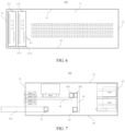
- Fig. 5 shows a schematic structural diagram of a network switch 100 along a top-down view according to some other embodiments of the present disclosure.
- the management unit plate 51 shown in Fig. 5 comprises a first management unit plate 511 and a second management unit plate 512, and the management unit plate 51 is adjacent to the second side plate 16.
- Fig. 6 shows a schematic structural diagram of the network switch 100 shown in Fig. 5 along a side view.
- the moving slot 111 comprises a first moving slot 1111 and a second moving slot 1112, and the first moving slot 1111 and the second moving slot 1112 are spaced apart from each other.
- the first management unit plate 511 is arranged in the first moving slot 1111, and the first management unit plate 511 is movable along the first moving slot 1111.
- the second management unit plate 512 is arranged in the second moving slot 1112, and the second management unit plate 512 is movable along the second moving slot 1112.
- the first management unit plate 511 and the second management unit plate 512 are respectively adjacent to the second side plate 16.
- the first connectors 42 are arranged in pairs on the switching unit plate 41, and the paired first connectors 42 are spaced apart from each other.
- the first management unit plate 511 and the second management unit plate 512 are respectively provided with the second connectors 52.
- the management unit 5 may be staggered from the input/output port 44 to avoid interference of the input/output port 44 with the movement of the management unit 5.
- the first management unit plate 511 and/or the second management unit plate 512 can be drawn out of the housing 1 through the first end plate 11, and the second connector 52 may be disconnected from the first connector 42.
- the first management unit plate 511 and/or the second management unit plate 512 are/is inserted into the housing 1 through the first end plate 11, and the second connector 52 may be connected to the first connector 42.
- the second connector 52 may be located on a side of the first management unit plate 511 away from the second side plate 16. Certainly, the second connector 52 may also be located on a side of the first management unit plate 511 facing the second side plate 16. In addition, the second connector 52 may be located on a side of the second management unit plate 512 away from the second side plate 16. Certainly, the second connector 52 may also be located on a side of the second management unit plate 512 facing the second side plate 16.
- the guide member 54 may be arranged at an end of the first management unit plate 511 adjacent to the second end plate 12, the guide member 54 may be arranged at an end of the second management unit plate 512 adjacent to the second end plate 12, and the guide member 54 may also be adjacent to the second connector 52.
- the switching unit plate 41 is provided with a guide groove mating with the guide member 54.
- the second connector 52 may be connected to the first connector 42.
- the network switch 100 can automatically switch to another management unit plate for access for working, so that the device does not power off, thereby avoiding the problem of device powering off caused by replacing the management unit plate 51.
- first management unit plate 511 and the second management unit plate 512 may also be respectively adjacent to the first side plate 15.
- one of the first management unit plate 511 and the second management unit plate 512 may be adjacent to the first side plate 15, and the other of the first management unit plate 511 and the second management unit plate 512 may be adjacent to the second side plate 16.
- Fig. 7 shows a schematic structural diagram of a network switch 100 along a front view according to some other embodiments of the present disclosure.
- the management unit 5 in Fig. 7 is adjacent to the bottom plate 14.
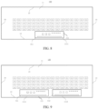
- Fig. 8 shows a schematic structural diagram of the network switch 100 shown in Fig. 7 along a side view.
- the moving slot 111 comprises a first moving slot 1111
- the management unit plate 51 comprises a first management unit plate 511.
- the first management unit plate 511 is arranged in the first moving slot 1111, and the first management unit plate 511 is movable along the first moving slot 1111.
- the first management unit plate 511 is adj acent to the bottom plate 14, then the switching unit plate 41 may be away from the bottom plate 14.
- the management unit 5 is staggered from the input/output port 44 to avoid interference of the input/output port 44 with the movement of the management unit 5.
- the switching unit 4 further comprises an adapter plate 43 connected to the switching unit plate 41, and the first connector 42 is arranged on the adapter plate 43, that is, the switching unit plate 41 and the management unit plate 51 are connected by the adapter plate 43.
- the first management unit plate 511 can be drawn out of the housing 1 through the first end plate 11, and the second connector 52 is disconnected from the first connector 42.
- the first management unit plate 511 By pushing the first management unit plate 511 in a direction toward the second end plate 12, the first management unit plate 511 can be inserted into the housing 1 through the first end plate 11, and the second connector 52 may be connected to the first connector 42.
- the second connector 52 may be located at an end of the first management unit plate 511 facing the second end plate 12.
- the guide member 54 may be arranged at an end of the first management unit plate 511 adjacent to the second end plate 12, and the guide member 54 may also be adjacent to the second connector 52.
- the adapter plate 43 is provided with a guide groove mating with the guide member 54.
- the second connector 52 may be connected to the first connector 42.
- the guide groove may also be arranged on a certain component in the housing 1, which is not limited here.
- the switching unit plate 41 is provided with a first adapter 411.
- An end of the adapter plate 43 adjacent to the switching unit plate 41 is provided with a second adapter 431 that can mate with the first adapter 411.
- the first connector 42 is arranged at an end of the adapter plate 43 away from the switching unit plate 41.
- the bottom plate 14 may be parallel to the switching unit plate 41.
- the adapter plate 43 may be arranged parallel to the first end plate 11; or the adapter plate 43 may also be arranged parallel to the first side plate 15, which is not limited here.
- Fig. 9 shows a schematic structural diagram of a network switch 100 along a side view according to some other embodiments of the present disclosure.
- the management unit plate 51 in Fig. 9 comprises a first management unit plate 511 and a second management unit plate 512, and the management unit plate 51 is adjacent to the bottom plate 14.
- the moving slot 111 may further comprise a first moving slot 1111 and a second moving slot 1112, and the first moving slot 1111 and the second moving slot 1112 are spaced apart from each other.
- the first management unit plate 511 and the second management unit plate 512 are respectively adj acent to the bottom plate 14.
- the first management unit plate 511 and the second management unit plate 512 are spaced apart from each other in a direction from the first side plate 15 to the second side plate 16. It should be noted that the manner of connection between the management unit plate 51 and the switching unit plate 41 in Fig. 9 is the same as that between the management unit plate 51 and the switching unit plate 41 in Figs. 7 and 8 , and details are not described herein.
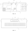
- Fig. 10 shows a schematic structural diagram of a network switch 100 along a front view according to some other embodiments of the present disclosure.
- the management unit 5 in Fig. 10 is away from the bottom plate 14.
- Fig. 11 shows a schematic structural diagram of the network switch 100 shown in Fig. 10 along a side view.
- the moving slot 111 may comprise a first moving slot 1111
- the management unit plate 51 may comprise a first management unit plate 511.
- the first management unit plate 511 is arranged in the first moving slot 1111, and the first management unit plate 511 is movable along the first moving slot 1111.
- the first management unit plate 511 is away from the bottom plate 14, then the switching unit plate 41 is adjacent to the bottom plate 14.
- the management unit 5 is staggered from the input/output port 44 to avoid interference of the input/output port 44 with the movement of the management unit 5.
- the switching unit 4 further comprises an adapter plate 43 connected to the switching unit plate 41, and the first connector 42 is arranged on the adapter plate 43, that is, the switching unit plate 41 and the management unit plate 51 are connected by the adapter plate 43.
- the first management unit plate 511 is pulled out of the housing 1 through the first end plate 11, and the second connector 52 is disconnected from the first connector 42.
- the first management unit plate 511 is inserted into the housing 1 through the first end plate 11, and the second connector 52 may be connected to the first connector 42.
- the second connector 52 may be located at an end of the first management unit plate 511 facing the second end plate 12.
- the guide member 54 may be arranged at an end of the first management unit plate 511 adjacent to the second end plate 12, and the guide member 54 may also be adjacent to the second connector 52.
- the adapter plate 43 is provided with a guide groove mating with the guide member 54.
- the second connector 52 may be connected to the first connector 42.
- the guide groove may also be arranged on a certain component in the housing 1, which is not limited here.
- the switching unit plate 41 is provided with a first adapter 411.
- An end of the adapter plate 43 adjacent to the switching unit plate 41 is provided with a second adapter 431 that can mate with the first adapter 411.
- the first connector 42 is arranged at an end of the adapter plate 43 away from the switching unit plate 41.
- the bottom plate 14 may be parallel to the switching unit plate 41.
- the adapter plate 43 may be arranged parallel to the first end plate 11; or the adapter plate 43 may also be arranged parallel to the first side plate 15, which is not limited here.
- the first management unit plate 511 and the second management unit plate 512 are spaced apart from each other in a direction from the first side plate 15 to the second side plate 16. It should be noted that the manner of the connection between the management unit plate 51 and the switching unit plate 41 in Fig. 12 is the same as that between the management unit plate 51 and the switching unit plate 41 in Figs. 10 and 11 , and details are not described herein.
- the design layout of the management unit 5 and the switching unit 4 according to the embodiments of the present disclosure may be applied to various network switches 100, so that when components on the management unit plate 51 fail, the entire device needs to be replaced, resulting in a cumbersome maintenance process and a high maintenance cost. It should be understood that the design layout of the management unit 5 and the switching unit 4 according to the embodiments of the present disclosure may also be applied to other components, which is not limited in the embodiments of the present disclosure.
- Example 2 The network switch according to Example 1, wherein a moving slot is provided on the first end plate, the management unit comprises a management unit plate provided with the second connector, and the management unit plate is arranged in the moving slot and is movable relative to the second end plate along the moving slot.
- Example 3 The network switch according to Example 2, wherein the moving slot comprises a first moving slot and a second moving slot spaced apart from each other, the management unit plate comprises a first management unit plate arranged in the first moving slot and a second management unit plate arranged in the second moving slot, and the management unit plate and the second management unit plate are respectively provided with the second connector.
Landscapes
- Engineering & Computer Science (AREA)
- Computer Hardware Design (AREA)
- General Engineering & Computer Science (AREA)
- Microelectronics & Electronic Packaging (AREA)
- Physics & Mathematics (AREA)
- Thermal Sciences (AREA)
- Computer Networks & Wireless Communication (AREA)
- Structure Of Telephone Exchanges (AREA)
Applications Claiming Priority (1)
| Application Number | Priority Date | Filing Date | Title |
|---|---|---|---|
| CN202311797543.6A CN117768423A (zh) | 2023-12-25 | 2023-12-25 | 网络交换机 |
Publications (1)
| Publication Number | Publication Date |
|---|---|
| EP4580323A1 true EP4580323A1 (de) | 2025-07-02 |
Family
ID=90315878
Family Applications (1)
| Application Number | Title | Priority Date | Filing Date |
|---|---|---|---|
| EP24220314.9A Pending EP4580323A1 (de) | 2023-12-25 | 2024-12-16 | Netzwerkschalter |
Country Status (4)
| Country | Link |
|---|---|
| US (1) | US12557238B2 (de) |
| EP (1) | EP4580323A1 (de) |
| CN (1) | CN117768423A (de) |
| WO (1) | WO2025139543A1 (de) |
Families Citing this family (2)
| Publication number | Priority date | Publication date | Assignee | Title |
|---|---|---|---|---|
| CN115175508B (zh) * | 2022-06-30 | 2023-08-04 | 超聚变数字技术有限公司 | 电子设备、机柜和服务器 |
| CN117768423A (zh) * | 2023-12-25 | 2024-03-26 | 北京字跳网络技术有限公司 | 网络交换机 |
Citations (2)
| Publication number | Priority date | Publication date | Assignee | Title |
|---|---|---|---|---|
| US20230164944A1 (en) * | 2021-11-22 | 2023-05-25 | Mellanox Technologies, Ltd. | Dual connect switch module |
| CN117061463A (zh) * | 2023-09-14 | 2023-11-14 | 北京字跳网络技术有限公司 | 网络交换机 |
Family Cites Families (7)
| Publication number | Priority date | Publication date | Assignee | Title |
|---|---|---|---|---|
| CN103138940B (zh) * | 2011-11-28 | 2016-06-01 | 英业达科技有限公司 | 服务器机架系统 |
| CN204633800U (zh) | 2015-05-25 | 2015-09-09 | 北京卓越信通电子股份有限公司 | 一种管理单元和交换单元双冗余的交换机 |
| US10568238B1 (en) * | 2018-08-10 | 2020-02-18 | Facebook, Inc. | Modular network switch |
| CN112394782A (zh) * | 2020-11-19 | 2021-02-23 | 北京比特大陆科技有限公司 | 服务器和具有其的数据中心 |
| CN214412941U (zh) | 2021-04-16 | 2021-10-15 | 朱继锋 | 一种便于维修的网络安全管理用交换机 |
| US11906800B2 (en) * | 2022-03-25 | 2024-02-20 | Arista Networks, Inc. | High speed network device with orthogonal pluggable optics modules |
| CN117768423A (zh) * | 2023-12-25 | 2024-03-26 | 北京字跳网络技术有限公司 | 网络交换机 |
-
2023
- 2023-12-25 CN CN202311797543.6A patent/CN117768423A/zh active Pending
-
2024
- 2024-11-26 WO PCT/CN2024/134698 patent/WO2025139543A1/zh active Pending
- 2024-12-16 EP EP24220314.9A patent/EP4580323A1/de active Pending
- 2024-12-18 US US18/985,515 patent/US12557238B2/en active Active
Patent Citations (2)
| Publication number | Priority date | Publication date | Assignee | Title |
|---|---|---|---|---|
| US20230164944A1 (en) * | 2021-11-22 | 2023-05-25 | Mellanox Technologies, Ltd. | Dual connect switch module |
| CN117061463A (zh) * | 2023-09-14 | 2023-11-14 | 北京字跳网络技术有限公司 | 网络交换机 |
Also Published As
| Publication number | Publication date |
|---|---|
| WO2025139543A1 (zh) | 2025-07-03 |
| US20250212356A1 (en) | 2025-06-26 |
| CN117768423A (zh) | 2024-03-26 |
| US12557238B2 (en) | 2026-02-17 |
Similar Documents
| Publication | Publication Date | Title |
|---|---|---|
| EP4580323A1 (de) | Netzwerkschalter | |
| EP2276332B1 (de) | Elektrisches System mit einer zurückziehbaren Einheit mit aufrechterhaltener Steuer- und Kommunikationsverbindung | |
| US7525809B2 (en) | Isolated control and network wireway for motor control center | |
| US7292457B2 (en) | Folding latching mechanism | |
| US4899254A (en) | Electronic module interconnection system | |
| EP2825010B1 (de) | Flüssigkeitskühlungsvorrichtung | |
| US10284010B2 (en) | Modular uninterruptible power supply system | |
| TW201933687A (zh) | 用於避免複合式卡接連接器插槽中之衝突之記憶體卡針腳佈局 | |
| US20260036139A1 (en) | Fan assembly, fan apparatus, and connector | |
| CN112312715A (zh) | 可限制不同模块安装顺序的电子装置及其机壳模块 | |
| CN108847538B (zh) | 一种功率电路用快速插头 | |
| WO2025055960A1 (zh) | 网络交换机 | |
| CN102063158A (zh) | 刀片服务器的io扩展模块 | |
| CN118567437A (zh) | 服务器 | |
| US11196196B2 (en) | Connection apparatus, network board connection system, and communications device | |
| US5570269A (en) | Magnetic disk module | |
| CN120406678B (zh) | 一种供电系统及服务器 | |
| CN112732605A (zh) | 一种服务器、主板转接存储模块及pcie信号转接板 | |
| CN119907226B (zh) | 机箱和机柜 | |
| KR101296233B1 (ko) | 멀티 입출력 제어장치 | |
| CN111836121B (zh) | 一种板卡连接架构及具有该架构的通信设备 | |
| CN215011210U (zh) | 一种应用于通信板卡的防反插结构 | |
| CN217721800U (zh) | 服务器机柜和服务器系统 | |
| CN220829658U (zh) | 门机控制板 | |
| CN218569760U (zh) | 一种对插式交流输入转接装置 |
Legal Events
| Date | Code | Title | Description |
|---|---|---|---|
| PUAI | Public reference made under article 153(3) epc to a published international application that has entered the european phase |
Free format text: ORIGINAL CODE: 0009012 |
|
| STAA | Information on the status of an ep patent application or granted ep patent |
Free format text: STATUS: REQUEST FOR EXAMINATION WAS MADE |
|
| 17P | Request for examination filed |
Effective date: 20241216 |
|
| AK | Designated contracting states |
Kind code of ref document: A1 Designated state(s): AL AT BE BG CH CY CZ DE DK EE ES FI FR GB GR HR HU IE IS IT LI LT LU LV MC ME MK MT NL NO PL PT RO RS SE SI SK SM TR |