EP4580290A1 - Verfahren und vorrichtung für autonomen übertragungsbetrieb von depriorisierten sidelink-daten - Google Patents
Verfahren und vorrichtung für autonomen übertragungsbetrieb von depriorisierten sidelink-daten Download PDFInfo
- Publication number
- EP4580290A1 EP4580290A1 EP23857718.3A EP23857718A EP4580290A1 EP 4580290 A1 EP4580290 A1 EP 4580290A1 EP 23857718 A EP23857718 A EP 23857718A EP 4580290 A1 EP4580290 A1 EP 4580290A1
- Authority
- EP
- European Patent Office
- Prior art keywords
- transmission
- sidelink
- period
- deprioritized
- channel
- Prior art date
- Legal status (The legal status is an assumption and is not a legal conclusion. Google has not performed a legal analysis and makes no representation as to the accuracy of the status listed.)
- Pending
Links
Images


Classifications
-
- H—ELECTRICITY
- H04—ELECTRIC COMMUNICATION TECHNIQUE
- H04W—WIRELESS COMMUNICATION NETWORKS
- H04W72/00—Local resource management
- H04W72/20—Control channels or signalling for resource management
- H04W72/25—Control channels or signalling for resource management between terminals via a wireless link, e.g. sidelink
-
- H—ELECTRICITY
- H04—ELECTRIC COMMUNICATION TECHNIQUE
- H04W—WIRELESS COMMUNICATION NETWORKS
- H04W72/00—Local resource management
- H04W72/40—Resource management for direct mode communication, e.g. D2D or sidelink
-
- H—ELECTRICITY
- H04—ELECTRIC COMMUNICATION TECHNIQUE
- H04L—TRANSMISSION OF DIGITAL INFORMATION, e.g. TELEGRAPHIC COMMUNICATION
- H04L1/00—Arrangements for detecting or preventing errors in the information received
- H04L1/12—Arrangements for detecting or preventing errors in the information received by using return channel
- H04L1/16—Arrangements for detecting or preventing errors in the information received by using return channel in which the return channel carries supervisory signals, e.g. repetition request signals
- H04L1/18—Automatic repetition systems, e.g. Van Duuren systems
- H04L1/1867—Arrangements specially adapted for the transmitter end
- H04L1/1887—Scheduling and prioritising arrangements
-
- H—ELECTRICITY
- H04—ELECTRIC COMMUNICATION TECHNIQUE
- H04W—WIRELESS COMMUNICATION NETWORKS
- H04W4/00—Services specially adapted for wireless communication networks; Facilities therefor
- H04W4/30—Services specially adapted for particular environments, situations or purposes
- H04W4/40—Services specially adapted for particular environments, situations or purposes for vehicles, e.g. vehicle-to-pedestrians [V2P]
-
- H—ELECTRICITY
- H04—ELECTRIC COMMUNICATION TECHNIQUE
- H04W—WIRELESS COMMUNICATION NETWORKS
- H04W72/00—Local resource management
- H04W72/04—Wireless resource allocation
- H04W72/115—Grant-free or autonomous transmission
-
- H—ELECTRICITY
- H04—ELECTRIC COMMUNICATION TECHNIQUE
- H04W—WIRELESS COMMUNICATION NETWORKS
- H04W92/00—Interfaces specially adapted for wireless communication networks
- H04W92/16—Interfaces between hierarchically similar devices
- H04W92/18—Interfaces between hierarchically similar devices between terminal devices
Definitions
- V2X Vehicle-to-everything
- V2X refers to a communication technology through which a vehicle exchanges information with another vehicle, a pedestrian, an object having an infrastructure (or infra) established therein, and so on.
- the V2X may be divided into 4 types, such as vehicle-to-vehicle (V2V), vehicle-to-infrastructure (V2I), vehicle-to-network (V2N), and vehicle-to-pedestrian (V2P).
- V2X communication may be provided via a PC5 interface and/or Uu interface.
- RAT Radio Access Technology
- V2X vehicle-to-everything
- a method for performing wireless communication by a first device may comprise: obtaining information related to a plurality of sidelink (SL) configured grants (CGs); configuring autonomous transmission for a logical channel related to a first SL CG included in the plurality of SL CGs; and deprioritizing the first SL CG for first SL transmission related to the logical channel in a first SL period of the first SL CG.
- the first device may be allowed to perform the first SL transmission in a second SL period of the deprioritized first SL CG.
- a processing device configured to control a first device.
- the processing device may comprise: at least one processor; and at least one memory connected to the at least one processor and storing instructions.
- the instructions based on being executed by the at least one processor, cause the first device to perform operations comprising: obtaining information related to a plurality of sidelink (SL) configured grants (CGs); configuring autonomous transmission for a logical channel related to a first SL CG included in the plurality of SL CGs; and deprioritizing the first SL CG for first SL transmission related to the logical channel in a first SL period of the first SL CG.
- the first device may be allowed to perform the first SL transmission in a second SL period of the deprioritized first SL CG.
- a non-transitory computer-readable storage medium recording instructions.
- the instructions based on being executed, cause a first device to perform operations comprising: obtaining information related to a plurality of sidelink (SL) configured grants (CGs); configuring autonomous transmission for a logical channel related to a first SL CG included in the plurality of SL CGs; and deprioritizing the first SL CG for first SL transmission related to the logical channel in a first SL period of the first SL CG.
- the first device may be allowed to perform the first SL transmission in a second SL period of the deprioritized first SL CG.
- At least one of A and B may mean “only A”, “only B”, or “both A and B”.
- the expression “at least one of A or B” or “at least one of A and/or B” may be interpreted as "at least one of A and B”.
- a parenthesis used in the present disclosure may mean “for example”.
- control information PDCCH
- PDCCH control information
- a parenthesis used in the present disclosure may mean “for example”.
- control information i.e., PDCCH
- PDCCH control information
- CDMA code division multiple access
- FDMA frequency division multiple access
- TDMA time division multiple access
- OFDMA orthogonal frequency division multiple access
- SC-FDMA single carrier frequency division multiple access
- the CDMA may be implemented with a radio technology, such as universal terrestrial radio access (UTRA) or CDMA-2000.
- UTRA universal terrestrial radio access
- the TDMA may be implemented with a radio technology, such as global system for mobile communications (GSM)/general packet ratio service (GPRS)/enhanced data rate for GSM evolution (EDGE).
- GSM global system for mobile communications
- GPRS general packet ratio service
- EDGE enhanced data rate for GSM evolution
- the OFDMA may be implemented with a radio technology, such as institute of electrical and electronics engineers (IEEE) 802.11 (Wi-Fi), IEEE 802.16 (WiMAX), IEEE 802.20, evolved UTRA (E-UTRA), and so on.
- IEEE 802.16m is an evolved version of IEEE 802.16e and provides backward compatibility with a system based on the IEEE 802.16e.
- the UTRA is part of a universal mobile telecommunication system (UMTS).
- 3rd generation partnership project (3GPP) long term evolution (LTE) is part of an evolved UMTS (E-UMTS) using the E-UTRA.
- the 3GPP LTE uses the OFDMA in a downlink and uses the SC-FDMA in an uplink.
- LTE-advanced (LTE-A) is an evolution of the LTE.
- 5G NR is a successive technology of LTE-A corresponding to a new Clean-slate type mobile communication system having the characteristics of high performance, low latency, high availability, and so on.
- 5G NR may use resources of all spectrum available for usage including low frequency bands of less than 1GHz, middle frequency bands ranging from 1GHz to 10GHz, high frequency (millimeter waves) of 24GHz or more, and so on.
- the 6G (wireless communication) system is aimed at (i) very high data rates per device, (ii) a very large number of connected devices, (iii) global connectivity, (iv) very low latency, (v) lower energy consumption for battery-free IoT devices, (vi) ultra-reliable connectivity, and (vii) connected intelligence with machine learning capabilities.
- the vision of the 6G system can have four aspects: intelligent connectivity, deep connectivity, holographic connectivity, and ubiquitous connectivity, and the 6G system can satisfy the requirements as shown in Table 1 below. In other words, Table 1 is an example of the requirements of a 6G system. [Table 1] Per device peak data rate 1 Tbps E2E latency 1 ms Maximum spectral efficiency 100bps/Hz Mobility support Up to 1000km/hr Satellite integration Fully AI Fully Autonomous vehicle Fully XR Fully Haptic Communication Fully
- 6G systems can have key elements such as enhanced mobile broadband (eMBB), ultra-reliable low latency communications (URLLC), massive machine-to-machine communications (mMTC), AI-integrated communications, tactile internet, high throughput, high network capacity, high energy efficiency, low backhaul and access network congestion, and enhanced data security.
- eMBB enhanced mobile broadband
- URLLC ultra-reliable low latency communications
- mMTC massive machine-to-machine communications
- AI-integrated communications tactile internet, high throughput, high network capacity, high energy efficiency, low backhaul and access network congestion, and enhanced data security.
- FIG. 1 shows a communication structure that can be provided in the 6G system, based on an embodiment of the present disclosure.
- the embodiment of FIG. 1 may be combined with various embodiments of the present disclosure.
- 6G systems are expected to have 50 times higher simultaneous radio connectivity than 5G radio systems.
- URLLC a key feature of 5G, will become a more dominant technology in 6G communications, providing end-to-end delay of less than 1 ms.
- 6G systems will have much better volumetric spectral efficiency as opposed to the more commonly used area spectral efficiency. 6G systems will be able to offer very long battery life and advanced battery technologies for energy harvesting, so mobile devices will not need to be charged separately in a 6G system.
- New network characteristics in 6G may include the following.
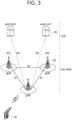
- the embodiment of FIG. 3 exemplifies a case where only the gNB is included.
- the BSs 20 may be connected to one another via Xn interface.
- the BS 20 may be connected to one another via 5th generation (5G) core network (5GC) and NG interface. More specifically, the BSs 20 may be connected to an access and mobility management function (AMF) 30 via NG-C interface, and may be connected to a user plane function (UPF) 30 via NG-U interface.
- 5G 5th generation
- GC 5th generation core network
- AMF access and mobility management function
- UPF user plane function
- Layers of a radio interface protocol between the UE and the network can be classified into a first layer (layer 1, L1), a second layer (layer 2, L2), and a third layer (layer 3, L3) based on the lower three layers of the open system interconnection (OSI) model that is well-known in the communication system.
- a physical (PHY) layer belonging to the first layer provides an information transfer service by using a physical channel
- a radio resource control (RRC) layer belonging to the third layer serves to control a radio resource between the UE and the network.
- the RRC layer exchanges an RRC message between the UE and the BS.
- the RLC layer performs concatenation, segmentation, and reassembly of Radio Link Control Service Data Unit (RLC SDU).
- RLC SDU Radio Link Control Service Data Unit
- TM transparent mode
- UM unacknowledged mode
- AM acknowledged mode
- An AM RLC provides error correction through an automatic repeat request (ARQ).
- a radio resource control (RRC) layer is defined only in the control plane.
- the RRC layer serves to control the logical channel, the transport channel, and the physical channel in association with configuration, reconfiguration and release of RBs.
- the RB is a logical path provided by the first layer (i.e., the physical layer or the PHY layer) and the second layer (i.e., a MAC layer, an RLC layer, a packet data convergence protocol (PDCP) layer, and a service data adaptation protocol (SDAP) layer) for data delivery between the UE and the network.
- the first layer i.e., the physical layer or the PHY layer
- the second layer i.e., a MAC layer, an RLC layer, a packet data convergence protocol (PDCP) layer, and a service data adaptation protocol (SDAP) layer
- SDAP service data adaptation protocol
- QoS Quality of Service
- DRB data radio bearer
- QFI QoS flow ID
- Data is transmitted from the network to the UE through a downlink transport channel.
- the downlink transport channel include a broadcast channel (BCH) for transmitting system information and a downlink-shared channel (SCH) for transmitting user traffic or control messages. Traffic of downlink multicast or broadcast services or the control messages can be transmitted on the downlink-SCH or an additional downlink multicast channel (MCH).
- Data is transmitted from the UE to the network through an uplink transport channel.
- Examples of the uplink transport channel include a random access channel (RACH) for transmitting an initial control message and an uplink SCH for transmitting user traffic or control messages.
- RACH random access channel
- Examples of logical channels belonging to a higher channel of the transport channel and mapped onto the transport channels include a broadcast channel (BCCH), a paging control channel (PCCH), a common control channel (CCCH), a multicast control channel (MCCH), a multicast traffic channel (MTCH), etc.
- BCCH broadcast channel
- PCCH paging control channel
- CCCH common control channel
- MCCH multicast control channel
- MTCH multicast traffic channel
- a radio frame may be used for performing uplink and downlink transmission.
- a radio frame has a length of 10ms and may be defined to be configured of two half-frames (HFs).
- a half-frame may include five 1ms subframes (SFs).
- a subframe (SF) may be divided into one or more slots, and the number of slots within a subframe may be determined based on subcarrier spacing (SCS).
- SCS subcarrier spacing
- Each slot may include 12 or 14 OFDM(A) symbols according to a cyclic prefix (CP).
- CP cyclic prefix
- OFDM(A) numerologies e.g., SCS, CP length, and so on
- a (absolute time) duration (or section) of a time resource e.g., subframe, slot or TTI
- a time unit (TU) for simplicity
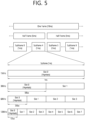
- FIG. 6 shows a structure of a slot of an NR frame, based on an embodiment of the present disclosure.
- the embodiment of FIG. 6 may be combined with various embodiments of the present disclosure.
- a slot includes a plurality of symbols in a time domain.
- one slot may include 14 symbols.
- one slot may include 12 symbols.
- one slot may include 7 symbols.
- one slot may include 6 symbols.
- bandwidth part BWP
- carrier a bandwidth part (BWP) and a carrier
- the BWP may be at least any one of an active BWP, an initial BWP, and/or a default BWP.
- the UE may not monitor downlink radio link quality in a DL BWP other than an active DL BWP on a primary cell (PCell).
- the UE may not receive PDCCH, physical downlink shared channel (PDSCH), or channel state information - reference signal (CSI-RS) (excluding RRM) outside the active DL BWP.
- the UE may not trigger a channel state information (CSI) report for the inactive DL BWP.
- the UE may not transmit physical uplink control channel (PUCCH) or physical uplink shared channel (PUSCH) outside an active UL BWP.
- PUCCH physical uplink control channel
- PUSCH physical uplink shared channel
- the initial BWP may be given as a consecutive RB set for a remaining minimum system information (RMSI) control resource set (CORESET) (configured by physical broadcast channel (PBCH)).
- RMSI remaining minimum system information
- CORESET control resource set
- PBCH physical broadcast channel
- SIB system information block
- the default BWP may be configured by a higher layer.
- an initial value of the default BWP may be an initial DL BWP.
- DCI downlink control information
- the BWP may be defined for SL.
- the same SL BWP may be used in transmission and reception.
- a transmitting UE may transmit a SL channel or a SL signal on a specific BWP
- a receiving UE may receive the SL channel or the SL signal on the specific BWP.
- the SL BWP may be defined separately from a Uu BWP, and the SL BWP may have configuration signaling separate from the Uu BWP.
- the UE may receive a configuration for the SL BWP from the BS/network.
- the UE may receive a configuration for the Uu BWP from the BS/network.
- FIG. 7 shows an example of a BWP, based on an embodiment of the present disclosure.
- the embodiment of FIG. 7 may be combined with various embodiments of the present disclosure. It is assumed in the embodiment of FIG. 7 that the number of BWPs is 3.
- a common resource block may be a carrier resource block numbered from one end of a carrier band to the other end thereof.
- the PRB may be a resource block numbered within each BWP.
- a point A may indicate a common reference point for a resource block grid.
- the BWP may be configured by a point A, an offset N start BWP from the point A, and a bandwidth N size BWP .
- the point A may be an external reference point of a PRB of a carrier in which a subcarrier 0 of all numerologies (e.g., all numerologies supported by a network on that carrier) is aligned.
- the offset may be a PRB interval between a lowest subcarrier and the point A in a given numerology.
- the bandwidth may be the number of PRBs in the given numerology.
- V2X or SL communication will be described.
- FIG. 8 shows a procedure of performing V2X or SL communication by a UE based on a transmission mode, based on an embodiment of the present disclosure.
- the transmission mode may be called a mode or a resource allocation mode.
- the transmission mode may be called an LTE transmission mode.
- the transmission mode may be called an NR resource allocation mode.
- (b) of FIG. 8 shows a UE operation related to an LTE transmission mode 2 or an LTE transmission mode 4.
- (b) of FIG. 8 shows a UE operation related to an NR resource allocation mode 2.
- the first UE may receive information related to dynamic grant (DG) resource(s) and/or information related to configured grant (CG) resource(s) from the base station.
- the CG resource(s) may include CG type 1 resource(s) or CG type 2 resource(s).
- the DG resource(s) may be resource(s) configured/allocated by the base station to the first UE through a downlink control information (DCI).
- the CG resource(s) may be (periodic) resource(s) configured/allocated by the base station to the first UE through a DCI and/or an RRC message.
- the base station may transmit an RRC message including information related to CG resource(s) to the first UE.
- the base station may transmit an RRC message including information related to CG resource(s) to the first UE, and the base station may transmit a DCI related to activation or release of the CG resource(s) to the first UE.
- the first UE may transmit a PSCCH (e.g., sidelink control information (SCI) or 1 st -stage SCI) to a second UE based on the resource scheduling.
- a PSCCH e.g., sidelink control information (SCI) or 1 st -stage SCI
- the first UE may transmit a PSSCH (e.g., 2 nd -stage SCI, MAC PDU, data, etc.) related to the PSCCH to the second UE.
- the first UE may receive a PSFCH related to the PSCCH/PSSCH from the second UE.
- HARQ feedback information e.g., NACK information or ACK information
- DCI format 3_0 is used for scheduling of NR PSCCH and NR PSSCH in one cell.
- the following information is transmitted by means of the DCI format 3_0 with CRC scrambled by SL-RNTI or SL-CS-RNTI:
- the sensing may be performed in a unit of subchannel(s).
- a first UE which has selected resource(s) from a resource pool by itself may transmit a PSCCH (e.g., sidelink control information (SCI) or 1 st -stage SCI) to a second UE by using the resource(s).
- the first UE may transmit a PSSCH (e.g., 2 nd -stage SCI, MAC PDU, data, etc.) related to the PSCCH to the second UE.
- the first UE may receive a PSFCH related to the PSCCH/PSSCH from the second UE.
- the first UE may transmit a SCI to the second UE through the PSCCH.
- the first UE may transmit two consecutive SCIs (e.g., 2-stage SCI) to the second UE through the PSCCH and/or the PSSCH.
- the second UE may decode two consecutive SCIs (e.g., 2-stage SCI) to receive the PSSCH from the first UE.
- a SCI transmitted through a PSCCH may be referred to as a 1 st SCI, a first SCI, a 1 st -stage SCI or a 1 st -stage SCI format, and a SCI transmitted through a PSSCH may be referred to as a 2 nd SCI, a second SCI, a 2 nd -stage SCI or a 2 nd -stage SCI format.
- the 1 st -stage SCI format may include a SCI format 1-A
- the 2 nd -stage SCI format may include a SCI format 2-A and/or a SCI format 2-B.
- SCI format 1-A is used for the scheduling of PSSCH and 2 nd -stage-SCI on PSSCH.
- SCI format 2-A is used for the decoding of PSSCH, with HARQ operation when HARQ-ACK information includes ACK or NACK, when HARQ-ACK information includes only NACK, or when there is no feedback of HARQ-ACK information.
- SCI format 2-B is used for the decoding of PSSCH, with HARQ operation when HARQ-ACK information includes only NACK, or when there is no feedback of HARQ-ACK information.
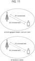
- FIG. 9 shows three cast types, based on an embodiment of the present disclosure.
- the embodiment of FIG. 9 may be combined with various embodiments of the present disclosure.
- (a) of FIG. 9 shows broadcast-type SL communication
- (b) of FIG. 9 shows unicast type-SL communication
- (c) of FIG. 9 shows groupcast-type SL communication.
- a UE may perform one-to-one communication with respect to another UE.
- the UE may perform SL communication with respect to one or more UEs in a group to which the UE belongs.
- SL groupcast communication may be replaced with SL multicast communication, SL one-to-many communication, or the like.
- SL DRX HARQ RTT timer the duration in which the UE performing the SL DRX operation operates in a sleep mode until receiving a retransmission packet (or PSSCH assignment) transmitted by other UE(s)
- the UE may determine that other UE(s) will not transmit a sidelink retransmission packet to the UE until the SL DRX HARQ RTT timer expires, and the UE may operate in a sleep mode while the corresponding timer is running. For example, if the UE starts the SL DRX HARQ RTT timer, the UE may not monitor a sidelink retransmission packet from other UE(s) until the SL DRX HARQ RTT timer expires.
- SL DRX retransmission timer the timer which starts when the SL DRX HARQ RTT timer expires, and the duration in which the UE performing the SL DRX operation operates in an active time in order to receive a retransmission packet (or PSSCH assignment) transmitted by other UE(s)
- a UE operating in sidelink DRX may operate in active mode during DRX active time (e.g., onduration timer, inactivity timer, retransmission timer, or duration when operating in active mode) to perform PSCCH/PSSCH monitoring.
- DRX active time e.g., onduration timer, inactivity timer, retransmission timer, or duration when operating in active mode
- the UE may operate in sleep mode during the sidelink DRX inactive time duration and not perform PSCCH/PSSCH monitoring operations for SL data reception.
- the transmission UE may configure the SL DRX configuration to be used by the reception UE that has established a unicast connection with the transmission UE directly and transmit it to the reception UE through a PC5 RRC message.
- the transmission UE While SL DRX is an operation for the reception UE, the transmission UE also needs to know the SL DRX operation status of the reception UE (active or sleep mode, or when the DRX onduration/inactivity/HARQ RTT/retransmission timer starts, when the DRX onduration/inactivity/HARQ RTT/retransmission timer expires, etc). For example, when allocating and transferring resources, the transmission UE should be able to determine whether the reception UE is operating in active mode or sleep mode. Therefore, the transmission UE may apply the same SL DRX configuration as the reception UE to maintain the same operation state of the SL DRX timer, etc. as the reception UE.
- interlaces of RBs may be defined in the frequency domain.
- An interlace m ⁇ ⁇ 0, 1, ..., M-1 ⁇ may consist of the (common) RBs ⁇ m, M+m, 2M+m, 3M+m, ... ⁇ , where M denotes the number of interlaced RBs given by Table 8. [Table 8] u M 0 10 1 5
- a communication device may use one or more interlaced RBs to transmit a signal/channel.
- a channel may refer to a set of frequency domain resources in which Listen-Before-Talk (LBT) is performed.
- LBT Listen-Before-Talk
- the channel may refer to an LBT bandwidth with 20 MHz and may have the same meaning as an RB set.
- the RB set may be defined in section 7 of 3GPP TS 38.214 V17.0.0.
- channel occupancy time may refer to time domain resources obtained by the base station or the UE after LBT success. It may be shared between the base station (or the UE) and the UE (or the base station) that obtained the CO, and this may be referred to as COT sharing. Depending on the initiating device, this may be referred to as gNB-initiated COT or UE-initiated COT.
- a cell operating in a licensed band may be defined as an L-cell, and a carrier of the L-cell may be defined as a (DL/UL/SL) LCC.
- a cell operating in an unlicensed band hereinafter, U-band
- U-band may be defined as a U-cell
- a carrier of the U-cell may be defined as a (DL/UL/SL) UCC.
- the carrier/carrier-frequency of a cell may refer to the operating frequency (e.g., center frequency) of the cell.
- a cell/carrier e.g., CC
- a cell/carrier is commonly called a cell.
- the LCC and the UCC may be configured as a primary CC (PCC) and a secondary CC (SCC), respectively.
- the base station and the UE may transmit and receive signals on one UCC or on a plurality of carrier-aggregated UCCs as shown in (b) of FIG. 11 .
- the base station and the UE may transmit and receive signals only on UCC(s) without using any LCC.
- PRACH transmission, PUCCH transmission, PUSCH transmission, SRS transmission, etc. may be supported on a UCell.
- the base station may be replaced with the UE.
- PSCCH transmission, PSSCH transmission, PSFCH transmission, S-SSB transmission, etc. may be supported on a UCell.
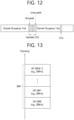
- FIG. 12 shows a method of occupying resources in an unlicensed band, based on an embodiment of the present disclosure.
- the embodiment of FIG. 12 may be combined with various embodiments of the present disclosure.
- a communication node within an unlicensed band should determine whether other communication node(s) is using a channel before signal transmission.
- the communication node within the unlicensed band may perform a channel access procedure (CAP) to access channel(s) on which transmission(s) is performed.
- the channel access procedure may be performed based on sensing.
- the communication node may perform carrier sensing (CS) before transmitting signals so as to check whether other communication node(s) perform signal transmission.
- CS carrier sensing
- a CCA threshold e.g., X Thresh
- a higher layer e.g., RRC
- the communication node may determine that the channel is busy if the detected channel energy is higher than the CCA threshold. Otherwise, the communication node may determine that the channel is idle. If it is determined that the channel is idle, the communication node may start the signal transmission in the unlicensed band.
- the CAP may be replaced with the LBT.
- Table 9 shows an example of the channel access procedure (CAP) supported in NR-U.
- Type Explanation DL Type 1 CAP CAP with random back-off - time duration spanned by the sensing slots that are sensed to be idle before a downlink transmission(s) is random
- Type 2 CAP - Type 2A, 2B, 2C CAP without random back-off - time duration spanned by sensing slots that are sensed to be idle before a downlink transmission(s) is deterministic UL or
- Type 1 CAP CAP with random back-off - time duration spanned by the sensing slots that are sensed to be idle before an uplink or sidelink transmission(s) is random Type 2 CAP - Type 2A, 2B, 2C CAP without random back-off - time duration spanned by sensing slots that are sensed to be idle before an uplink or sidelink transmission(s) is deterministic
- the LBT type or CAP for DL/UL/SL transmission may be defined.
- Table 9 is only an example, and a new type or CAP may be defined in a similar manner.
- the type 1 also referred to as Cat-4 LBT
- the contention window may change.
- the type 2 can be performed in case of COT sharing within COT acquired by the base station (gNB) or the UE.
- a plurality of LBT-SBs may be included in the BWP of a cell (or carrier).
- An LBT-SB may have, for example, a 20-MHz band.
- the LBT-SB may include a plurality of contiguous (P)RBs in the frequency domain, and thus may be referred to as a (P)RB set.
- a guard band (GB) may be interposed between LBT-SBs.
- the BWP may be configured in the form of ⁇ LBT-SB #0 (RB set #0)+GB #0+LBT-SB #1 (RB set #1+GB #1) + ... +LBT-SB #(K-1) (RB set (#K-1)) ⁇ .
- LBT-SB/RB indexes may be configured/defined in an increasing order from the lowest frequency to the highest frequency.
- CAC channel access priority class
- the CAPCs of MAC CEs and radio bearers may be fixed or configured to operate in FR1:
- the base station When selecting a CAPC of a DRB, the base station considers fairness between other traffic types and transmissions while considering 5QI of all QoS flows multiplexed to the corresponding DRB.
- Table 10 shows which CAPC should be used for standardized 5QI, that is, a CAPC to be used for a given QoS flow.
- CAPCs are defined as shown in the table below, and for non-standardized 5QI, the CAPC with the best QoS characteristics should be used.
- HARQ-ACK feedback e.g., the ratio of ACK or NACK
- CW p may be initialized to CW min,p based on the HARQ-ACK feedback for the previous DL burst.
- CW p may be increased to the next higher allowed value or maintained as it is.
- the UE may attempt to transmit data by occupying the channel. For example, if the UE detects a collision when it attempts to transmit data, it may increase the contention window size (CW size) mapped to the CAPC. In addition, the UE may reselect a random value for the backoff count between 0 and CW which is reselected through the increased CW. For example, if the UE succeeds in packet transmission, the contention window (CW size) may be initialized to a default value mapped to the initial CAPC.
- m p may be a constant mapped per CAPC and be used for calculating the T d .
- m p may be mapped to smaller values as the CAPC value decrease (or the priority increases).
- the type 2B may be 16 usec one-shot LBT.
- transmission may start immediately after idle sensing for a 16 usec gap. That is, the UE may sense a channel for 16 usec within COT, and if the channel is idle, the UE may attempt to transmit data by occupying the channel.
- the UE may continually perform transmission of the previous sidelink data transmitted through that sidelink process until the timer expire. For example, the UE may trigger transmission of the initial TB (or retransmission TB) using configured grant resource or if the sidelink grant for the initial TB (or retransmission TB) is scheduled or allocated, the UE may start the sidelink configured grant timer. For example, if the timer expires, the UE may reuse the sidelink process which is in use for the sidelink data transmitted within the current configured grant period for new sidelink data transmission purpose using the configured grant resource of the next period.
- the channel of the unlicensed band should be occupied to transmit sidelink data first.
- the UE may perform (type 1) LBT operation to occupy the channel of the unlicensed band, and only when the channel is idle, the channel may be occupied and sidelink data or TB may be transmitted through the occupied channel.
- the (type 1) LBT procedure fails, the UE should reperform the LBT procedure and transmit the sidelink data only after the LBT is successful. That is, for example, when the LBT procedure fails, there may be a latency in sidelink data transmission equal to the time it takes to perform the LBT.
- the UE may report NACK to the base through the PUCCH and may be allocated mode 1 dynamic grant to transmit the sidelink retransmission TB to the counterpart UE. For example, if the LBT procedure of the UE for PUCCH transmission in the unlicensed band fails, the latency for sidelink data transmission may occur equal to the time it takes to perform the LBT. In this case, for example, it may not satisfy the QoS requirement (e.g., packet delay budget (PDB)) of the sidelink data.
- PDB packet delay budget
- the UE may use the configured grant resource of the next period for the retransmission resource.
- a sidelink configured grant retransmission timer is proposed.
- the sidelink configured grant retransmission timer is a timer that allows the configured grant resource of the next period to be used as retransmission resources of the TB transmitted using the configured grant of the current period.
- the configured grant resource of the next period may not be used for retransmission purpose of the TB transmitted using the configured grant of the current period.
- the UE may use the configured grant resource of the next period for the retransmission purpose of the TB transmitted using the configured grant of the current period.
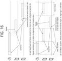
- the UE may transmit the sidelink TB using the sidelink mode 1 configured grant in the sidelink unlicensed band. For example, when the UE transmit SL TB to the counterpart UE using a first resource within the current period, the UE may start the sidelink configured grant retransmission timer. For example, when the UE transmits the SL TB to the counterpart UE using the first resource of the current period and receives HARQ negative feedback for that transmission, it may transmit the retransmission TB to the counterpart reception UE using next resource of the current period and restart the sidelink configured grant retransmission timer. For example, if receiving HARQ negative feedback from the counterpart reception UE again, it may transmit the retransmission packet using a third resource (e.g., last resource) of the current period and restart the sidelink configured grant retransmission timer.
- a third resource e.g., last resource
- the UE may start the sidelink configured grant retransmission timer only when (re)transmitting the TB using the last configured grant (CG) of the period.
- the UE may start the sidelink configured grant retransmission timer when the last CG of the period for the retransmission is ready.
- the UE may not perform PUCCH transmission (HARQ NACK feedback) (when PUCCH resource is configured) to the base station, and if the sidelink configured grant retransmission timer expires and the configured grant of the next period occurs, the UE may transmit the retransmission TB to the counterpart reception UE using the CG resource of the next period.
- PUCCH transmission HARQ NACK feedback
- autonomous transmission operations and the sidelink configured grant retransmission operations which are proposed in the present disclosure may be combined and operated as follows.
- the UE may start the sidelink configured grant retransmission timer when the sidelink configured grant resource (or mode 1 dynamic grant for the initial transmission) for the retransmission data transmission is scheduled.
- the UE may determine a priority of data to be transmitted depending on the prioritization rule. For example, if the sidelink data or sidelink MAC CE is determined as the deprioritized transmission (data or MAC CE) depending on the prioritization rule, the sidelink grant (e.g., mode 1 sidelink configured grant or mode 2 sidelink selected grant) selected for transmission of that retransmission sidelink data or retransmission sidelink MAC CE may be considered as the deprioritized sidelink grant.
- the sidelink grant e.g., mode 1 sidelink configured grant or mode 2 sidelink selected grant
- the UE may stop the sidelink configured grant retransmission timer and retransmit the deprioritized sidelink data (or MAC CE) using the sidelink configured grant resource of the next period of the deprioritized sidelink grant (e.g., among the sidelnik grants, autonomous transmission operation may be performed only for the grant for which the base station has configured autonomous transmission). That is, for example, the UE may reuse the sidelink process which was used within the previous sidelink configured grant period and may retransmit the deprioritized sidelink data (or MAC CE) by allocating (or linking) the deprioritized sidelink data (or MAC CE) to the previous sidelink process using the sidelink configured grant of the next period.
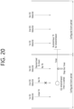
- FIG. 20 shows an operation of UE performing autonomous transmission for retransmission when the retransmission sidelink data is a deprioritized transmission, based on an embodiment of the present disclosure.
- the embodiment of FIG. 20 may be combined with various embodiments of the present disclosure.
- the sidelink grant (when the autonomous SL transmission is configured to the sidelink grant) for that data transmission can be the deprioritized SL grant. Furthermore, at the moment the deprioritized grant is created, it may stop the sidelink configured grant retransmission timer and perform the autonomous transmission for the retransmission of the deprioritized data within the resources of the next period of the deprioritized SL grant.
- the sidelink data or MAC CE that could not be transmitted due to the LBT failure can be the deprioritized data MAC CE, and also the grant for transmitting the sidelink data or MAC CE may be considered as the deprioritized sidelink grant.
- the wording of the sidelink configured grant timer or sidelink configured grant retransmission timer proposed in the present disclosure is only an example, and the operations based on that timers may also be applied to mode 2 operations. That is, for example, even in mode 2 operations, mode 2 resource may be used for periodic transmission purpose (e.g., multiple MAC PDU transmission) with periodicity, as mode 1 configured grant, so the proposal of the present disclosure may be equally applied to the mode 2 operation.
- mode 2 resource may be used for periodic transmission purpose (e.g., multiple MAC PDU transmission) with periodicity, as mode 1 configured grant, so the proposal of the present disclosure may be equally applied to the mode 2 operation.
- the channels specified in this disclosure may be applied by replacing a carrier, a set of resource block (RB) of a specific carrier, or a band.
- RB resource block
- whether or not the (some) proposed method/rule of the present disclosure is applied and/or related parameter(s) may be configured (differently or independently) for each SL-Channel Access Priority Class (CAPC).
- whether or not the (some) proposed method/rule of the present disclosure is applied and/or related parameter(s) (e.g., threshold value(s)) may be configured (differently or independently) for each SL-LBT type (e.g., Type 1 LBT, Type 2A LBT, Type 2B LBT, Type 2C LBT).
- whether or not the (some) proposed method/rule of the present disclosure is applied and/or related parameter(s) may be configured specifically (or differently or independently) depending on whether or not Frame Based LBT is applied.
- whether or not the (some) proposed method/rule of the present disclosure is applied and/or related parameter(s) (e.g., threshold value(s)) may be configured specifically (or differently or independently) depending on whether or not Load Based LBT is applied.
- whether or not the (some) proposed method/rule of the present disclosure is applied and/or related parameter(s) may be configured (differently or independently) for each resource pool. For example, whether or not the (some) proposed method/rule of the present disclosure is applied and/or related parameter(s) (e.g., threshold value(s)) may be configured (differently or independently) for each congestion level. For example, whether or not the (some) proposed method/rule of the present disclosure is applied and/or related parameter(s) (e.g., threshold value(s)) may be configured (differently or independently) for each service priority.
- whether or not the (some) proposed method/rule of the present disclosure is applied and/or related parameter(s) may be configured (differently or independently) for each service type.
- whether or not the (some) proposed method/rule of the present disclosure is applied and/or related parameter(s) (e.g., threshold value(s)) may be configured (differently or independently) for each QoS requirement (e.g., latency, reliability).
- whether or not the (some) proposed method/rule of the present disclosure is applied and/or related parameter(s) may be configured (differently or independently) for each PQI (5G QoS identifier (5QI) for PC5).
- whether or not the (some) proposed method/rule of the present disclosure is applied and/or related parameter(s) (e.g., threshold value(s)) may be configured (differently or independently) for each traffic type (e.g., periodic generation or aperiodic generation).
- whether or not the (some) proposed method/rule of the present disclosure is applied and/or related parameter(s) may be configured (differently or independently) for each SL transmission resource allocation mode (e.g., mode 1 or mode 2).
- whether or not the (some) proposed method/rule of the present disclosure is applied and/or related parameter(s) (e.g., threshold value(s)) may be configured (differently or independently) for each Tx profile (e.g., a Tx profile indicating that a service supports sidelink DRX operation or a Tx profile indicating that a service does not need to support sidelink DRX operation).
- whether or not the proposed rule of the present disclosure is applied and/or related parameter configuration value(s) may be configured (differently or independently) depending on whether the PUCCH configuration is supported (e.g., in case that a PUCCH resource is configured or in case that a PUCCH resource is not configured).
- whether or not the proposed rule of the present disclosure is applied and/or related parameter configuration value(s) may be configured (differently or independently) for each resource pool (e.g., a resource pool with a PSFCH or a resource pool without a PSFCH).
- whether or not the proposed rule of the present disclosure is applied and/or related parameter configuration value(s) may be configured (differently or independently) for each service/packet type.
- whether or not the proposed rule of the present disclosure is applied and/or related parameter configuration value(s) may be configured (differently or independently) for each service/packet priority.
- whether or not the proposed rule of the present disclosure is applied and/or related parameter configuration value(s) may be configured (differently or independently) for each QoS requirement (e.g., URLLC/EMBB traffic, reliability, latency).
- QoS requirement e.g., URLLC/EMBB traffic, reliability, latency
- whether or not the proposed rule of the present disclosure is applied and/or related parameter configuration value(s) may be configured (differently or independently) for each PQI.
- whether or not the proposed rule of the present disclosure is applied and/or related parameter configuration value(s) may be configured (differently or independently) for each PFI.
- the first device may initiate a SL CG timer.
- the first device may not be allowed to perform the first SL transmission in the second SL period of the first SL CG by reusing a SL process used for the first SL transmission in the first SL period of the first SL CG during the SL CG timer running.
- the first device may stop the initiated SL CG timer based on the first SL CG being deprioritized.
- the first device may be allowed to perform the first SL transmission in a second SL period of the deprioritized first SL CG, based on the SL CG timer being stopped.
- the vehicles may include a vehicle having a wireless communication function, an autonomous vehicle, and a vehicle capable of performing communication between vehicles.
- the vehicles may include an Unmanned Aerial Vehicle (UAV) (e.g., a drone).
- UAV Unmanned Aerial Vehicle
- the XR device may include an Augmented Reality (AR)/Virtual Reality (VR)/Mixed Reality (MR) device and may be implemented in the form of a Head-Mounted Device (HMD), a Head-Up Display (HUD) mounted in a vehicle, a television, a smartphone, a computer, a wearable device, a home appliance device, a digital signage, a vehicle, a robot, etc.
- the hand-held device may include a smartphone, a smartpad, a wearable device (e.g., a smartwatch or a smartglasses), and a computer (e.g., a notebook).
- the home appliance may include a TV, a refrigerator, and a washing machine.
- the IoT device may include a sensor and a smartmeter.
- the BSs and the network may be implemented as wireless devices and a specific wireless device 200a may operate as a BS/network node with respect to other wireless devices.
- the wireless devices 100a to 100f may be connected to the network 300 via the BSs 200.
- An AI technology may be applied to the wireless devices 100a to 100f and the wireless devices 100a to 100f may be connected to the AI server 400 via the network 300.
- the network 300 may be configured using a 3G network, a 4G (e.g., LTE) network, or a 5G (e.g., NR) network.
- the wireless devices 100a to 100f may communicate with each other through the BSs 200/network 300, the wireless devices 100a to 100f may perform direct communication (e.g., sidelink communication) with each other without passing through the BSs/network.
- the vehicles 100b-1 and 100b-2 may perform direct communication (e.g.
- Wireless communication/connections 150a, 150b, or 150c may be established between the wireless devices 100a to 100f/BS 200, or BS 200/BS 200.
- the wireless communication/connections may be established through various RATs (e.g., 5G NR) such as uplink/downlink communication 150a, sidelink communication 150b (or, D2D communication), or inter BS communication (e.g. relay, Integrated Access Backhaul (IAB)).
- the wireless devices and the BSs/the wireless devices may transmit/receive radio signals to/from each other through the wireless communication/connections 150a and 150b.
- the wireless communication/connections 150a and 150b may transmit/receive signals through various physical channels.
- various configuration information configuring processes various signal processing processes (e.g., channel encoding/decoding, modulation/demodulation, and resource mapping/demapping), and resource allocating processes, for transmitting/receiving radio signals, may be performed based on the various proposals of the present disclosure.
- various signal processing processes e.g., channel encoding/decoding, modulation/demodulation, and resource mapping/demapping
- resource allocating processes for transmitting/receiving radio signals
- a first wireless device 100 and a second wireless device 200 may transmit radio signals through a variety of RATs (e.g., LTE and NR).
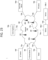
- ⁇ the first wireless device 100 and the second wireless device 200 ⁇ may correspond to ⁇ the wireless device 100x and the BS 200 ⁇ and/or ⁇ the wireless device 100x and the wireless device 100x ⁇ of FIG. 23 .
- the first wireless device 100 may include one or more processors 102 and one or more memories 104 and additionally further include one or more transceivers 106 and/or one or more antennas 108.
- the processor(s) 102 may control the memory(s) 104 and/or the transceiver(s) 106 and may be configured to implement the descriptions, functions, procedures, proposals, methods, and/or operational flowcharts disclosed in this document.
- the processor(s) 102 may process information within the memory(s) 104 to generate first information/signals and then transmit radio signals including the first information/signals through the transceiver(s) 106.
- the processor(s) 102 may receive radio signals including second information/signals through the transceiver 106 and then store information obtained by processing the second information/signals in the memory(s) 104.
- the memory(s) 104 may be connected to the processor(s) 102 and may store a variety of information related to operations of the processor(s) 102.
- the memory(s) 104 may store software code including commands for performing a part or the entirety of processes controlled by the processor(s) 102 or for performing the descriptions, functions, procedures, proposals, methods, and/or operational flowcharts disclosed in this document.
- the processor(s) 102 and the memory(s) 104 may be a part of a communication modem/circuit/chip designed to implement RAT (e.g., LTE or NR).
- the transceiver(s) 106 may be connected to the processor(s) 102 and transmit and/or receive radio signals through one or more antennas 108.
- Each of the transceiver(s) 106 may include a transmitter and/or a receiver.
- the transceiver(s) 106 may be interchangeably used with Radio Frequency (RF) unit(s).
- the wireless device may represent a communication modem/circuit/chip.
- the processor(s) 202 may receive radio signals including fourth information/signals through the transceiver(s) 106 and then store information obtained by processing the fourth information/signals in the memory(s) 204.
- the memory(s) 204 may be connected to the processor(s) 202 and may store a variety of information related to operations of the processor(s) 202.
- the memory(s) 204 may store software code including commands for performing a part or the entirety of processes controlled by the processor(s) 202 or for performing the descriptions, functions, procedures, proposals, methods, and/or operational flowcharts disclosed in this document.
- the processor(s) 202 and the memory(s) 204 may be a part of a communication modem/circuit/chip designed to implement RAT (e.g., LTE or NR).
- the transceiver(s) 206 may be connected to the processor(s) 202 and transmit and/or receive radio signals through one or more antennas 208.
- Each of the transceiver(s) 206 may include a transmitter and/or a receiver.
- the transceiver(s) 206 may be interchangeably used with RF unit(s).
- the wireless device may represent a communication modem/circuit/chip.
- One or more protocol layers may be implemented by, without being limited to, one or more processors 102 and 202.
- the one or more processors 102 and 202 may implement one or more layers (e.g., functional layers such as PHY, MAC, RLC, PDCP, RRC, and SDAP).
- the one or more processors 102 and 202 may generate one or more Protocol Data Units (PDUs) and/or one or more Service Data Unit (SDUs) according to the descriptions, functions, procedures, proposals, methods, and/or operational flowcharts disclosed in this document.
- PDUs Protocol Data Units
- SDUs Service Data Unit
- the one or more processors 102 and 202 may generate messages, control information, data, or information according to the descriptions, functions, procedures, proposals, methods, and/or operational flowcharts disclosed in this document.
- the one or more processors 102 and 202 may generate signals (e.g., baseband signals) including PDUs, SDUs, messages, control information, data, or information according to the descriptions, functions, procedures, proposals, methods, and/or operational flowcharts disclosed in this document and provide the generated signals to the one or more transceivers 106 and 206.
- the one or more processors 102 and 202 may receive the signals (e.g., baseband signals) from the one or more transceivers 106 and 206 and acquire the PDUs, SDUs, messages, control information, data, or information according to the descriptions, functions, procedures, proposals, methods, and/or operational flowcharts disclosed in this document.
- signals e.g., baseband signals
- the one or more processors 102 and 202 may be referred to as controllers, microcontrollers, microprocessors, or microcomputers.
- the one or more processors 102 and 202 may be implemented by hardware, firmware, software, or a combination thereof.
- ASICs Application Specific Integrated Circuits
- DSPs Digital Signal Processors
- DSPDs Digital Signal Processing Devices
- PLDs Programmable Logic Devices
- FPGAs Field Programmable Gate Arrays
- the descriptions, functions, procedures, proposals, methods, and/or operational flowcharts disclosed in this document may be implemented using firmware or software and the firmware or software may be configured to include the modules, procedures, or functions.
- Firmware or software configured to perform the descriptions, functions, procedures, proposals, methods, and/or operational flowcharts disclosed in this document may be included in the one or more processors 102 and 202 or stored in the one or more memories 104 and 204 so as to be driven by the one or more processors 102 and 202.
- the descriptions, functions, procedures, proposals, methods, and/or operational flowcharts disclosed in this document may be implemented using firmware or software in the form of code, commands, and/or a set of commands.
- the one or more memories 104 and 204 may be connected to the one or more processors 102 and 202 and store various types of data, signals, messages, information, programs, code, instructions, and/or commands.
- the one or more memories 104 and 204 may be configured by Read-Only Memories (ROMs), RandomAccess Memories (RAMs), Electrically Erasable Programmable Read-Only Memories (EPROMs), flash memories, hard drives, registers, cash memories, computer-readable storage media, and/or combinations thereof.
- the one or more memories 104 and 204 may be located at the interior and/or exterior of the one or more processors 102 and 202.
- the one or more memories 104 and 204 may be connected to the one or more processors 102 and 202 through various technologies such as wired or wireless connection.
- the one or more transceivers 106 and 206 may transmit user data, control information, and/or radio signals/channels, mentioned in the methods and/or operational flowcharts of this document, to one or more other devices.
- the one or more transceivers 106 and 206 may receive user data, control information, and/or radio signals/channels, mentioned in the descriptions, functions, procedures, proposals, methods, and/or operational flowcharts disclosed in this document, from one or more other devices.
- the one or more transceivers 106 and 206 may be connected to the one or more processors 102 and 202 and transmit and receive radio signals.
- the one or more processors 102 and 202 may perform control so that the one or more transceivers 106 and 206 may transmit user data, control information, or radio signals to one or more other devices.
- the one or more processors 102 and 202 may perform control so that the one or more transceivers 106 and 206 may receive user data, control information, or radio signals from one or more other devices.
- the one or more transceivers 106 and 206 may be connected to the one or more antennas 108 and 208 and the one or more transceivers 106 and 206 may be configured to transmit and receive user data, control information, and/or radio signals/channels, mentioned in the descriptions, functions, procedures, proposals, methods, and/or operational flowcharts disclosed in this document, through the one or more antennas 108 and 208.
- the one or more antennas may be a plurality of physical antennas or a plurality of logical antennas (e.g., antenna ports).
- the one or more transceivers 106 and 206 may convert received radio signals/channels etc.
- the one or more transceivers 106 and 206 may convert the user data, control information, radio signals/channels, etc. processed using the one or more processors 102 and 202 from the base band signals into the RF band signals.
- the one or more transceivers 106 and 206 may include (analog) oscillators and/or filters.
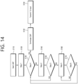
- FIG. 25 shows a signal process circuit for a transmission signal, based on an embodiment of the present disclosure.
- the embodiment of FIG. 25 may be combined with various embodiments of the present disclosure.
- a signal processing circuit 1000 may include scramblers 1010, modulators 1020, a layer mapper 1030, a precoder 1040, resource mappers 1050, and signal generators 1060.
- An operation/function of FIG. 25 may be performed, without being limited to, the processors 102 and 202 and/or the transceivers 106 and 206 of FIG. 24 .
- Hardware elements of FIG. 25 may be implemented by the processors 102 and 202 and/or the transceivers 106 and 206 of FIG. 24 .
- blocks 1010 to 1060 may be implemented by the processors 102 and 202 of FIG. 24 .
- the blocks 1010 to 1050 may be implemented by the processors 102 and 202 of FIG. 24 and the block 1060 may be implemented by the transceivers 106 and 206 of FIG. 24 .
- Codewords may be converted into radio signals via the signal processing circuit 1000 of FIG. 25 .
- the codewords are encoded bit sequences of information blocks.
- the information blocks may include transport blocks (e.g., a UL-SCH transport block, a DL-SCH transport block).
- the radio signals may be transmitted through various physical channels (e.g., a PUSCH and a PDSCH).
- the codewords may be converted into scrambled bit sequences by the scramblers 1010.
- Scramble sequences used for scrambling may be generated based on an initialization value, and the initialization value may include ID information of a wireless device.
- the scrambled bit sequences may be modulated to modulation symbol sequences by the modulators 1020.
- a modulation scheme may include pi/2-Binary Phase Shift Keying (pi/2-BPSK), m-Phase Shift Keying (m-PSK), and m-Quadrature Amplitude Modulation (m-QAM).
- Complex modulation symbol sequences may be mapped to one or more transport layers by the layer mapper 1030.
- Modulation symbols of each transport layer may be mapped (precoded) to corresponding antenna port(s) by the precoder 1040.
- Outputs z of the precoder 1040 may be obtained by multiplying outputs y of the layer mapper 1030 by an N*M precoding matrix W.
- N is the number of antenna ports and M is the number of transport layers.
- the precoder 1040 may perform precoding after performing transform precoding (e.g., DFT) for complex modulation symbols. Alternatively, the precoder 1040 may perform precoding without performing transform precoding.
- transform precoding e.g., DFT
- the resource mappers 1050 may map modulation symbols of each antenna port to time-frequency resources.
- the time-frequency resources may include a plurality of symbols (e.g., a CP-OFDMA symbols and DFT-s-OFDMA symbols) in the time domain and a plurality of subcarriers in the frequency domain.
- the signal generators 1060 may generate radio signals from the mapped modulation symbols and the generated radio signals may be transmitted to other devices through each antenna.
- the signal generators 1060 may include Inverse Fast Fourier Transform (IFFT) modules, Cyclic Prefix (CP) inserters, Digital-to-Analog Converters (DACs), and frequency up-converters.
- IFFT Inverse Fast Fourier Transform
- CP Cyclic Prefix
- DACs Digital-to-Analog Converters
- Signal processing procedures for a signal received in the wireless device may be configured in a reverse manner of the signal processing procedures 1010 to 1060 of FIG. 25 .
- the wireless devices e.g., 100 and 200 of FIG. 24
- the received radio signals may be converted into baseband signals through signal restorers.
- the signal restorers may include frequency downlink converters, Analog-to-Digital Converters (ADCs), CP remover, and Fast Fourier Transform (FFT) modules.
- ADCs Analog-to-Digital Converters
- FFT Fast Fourier Transform
- the baseband signals may be restored to codewords through a resource demapping procedure, a postcoding procedure, a demodulation processor, and a descrambling procedure.
- a signal processing circuit for a reception signal may include signal restorers, resource demappers, a postcoder, demodulators, descramblers, and decoders.
- FIG. 26 shows another example of a wireless device, based on an embodiment of the present disclosure.
- the wireless device may be implemented in various forms according to a use-case/service (refer to FIG. 23 ).
- the embodiment of FIG. 26 may be combined with various embodiments of the present disclosure.
- wireless devices 100 and 200 may correspond to the wireless devices 100 and 200 of FIG. 24 and may be configured by various elements, components, units/portions, and/or modules.
- each of the wireless devices 100 and 200 may include a communication unit 110, a control unit 120, a memory unit 130, and additional components 140.
- the communication unit may include a communication circuit 112 and transceiver(s) 114.
- the communication circuit 112 may include the one or more processors 102 and 202 and/or the one or more memories 104 and 204 of FIG. 24 .
- the transceiver(s) 114 may include the one or more transceivers 106 and 206 and/or the one or more antennas 108 and 208 of FIG. 24 .
- the control unit 120 is electrically connected to the communication unit 110, the memory 130, and the additional components 140 and controls overall operation of the wireless devices. For example, the control unit 120 may control an electric/mechanical operation of the wireless device based on programs/code/commands/information stored in the memory unit 130.
- the control unit 120 may transmit the information stored in the memory unit 130 to the exterior (e.g., other communication devices) via the communication unit 110 through a wireless/wired interface or store, in the memory unit 130, information received through the wireless/wired interface from the exterior (e.g., other communication devices) via the communication unit 110.
- the additional components 140 may be variously configured according to types of wireless devices.
- the additional components 140 may include at least one of a power unit/battery, input/output (I/O) unit, a driving unit, and a computing unit.
- the wireless device may be implemented in the form of, without being limited to, the robot (100a of FIG. 23 ), the vehicles (100b-1 and 100b-2 of FIG. 23 ), the XR device (100c of FIG. 23 ), the hand-held device (100d of FIG. 23 ), the home appliance (100e of FIG. 23 ), the IoT device (100f of FIG.
- the wireless device may be used in a mobile or fixed place according to a use-example/service.
- the entirety of the various elements, components, units/portions, and/or modules in the wireless devices 100 and 200 may be connected to each other through a wired interface or at least a part thereof may be wirelessly connected through the communication unit 110.
- the control unit 120 and the communication unit 110 may be connected by wire and the control unit 120 and first units (e.g., 130 and 140) may be wirelessly connected through the communication unit 110.
- Each element, component, unit/portion, and/or module within the wireless devices 100 and 200 may further include one or more elements.
- the control unit 120 may be configured by a set of one or more processors.
- FIG. 26 An example of implementing FIG. 26 will be described in detail with reference to the drawings.
- FIG. 27 shows a hand-held device, based on an embodiment of the present disclosure.
- the hand-held device may include a smartphone, a smartpad, a wearable device (e.g., a smartwatch or a smartglasses), or a portable computer (e.g., a notebook).
- the hand-held device may be referred to as a mobile station (MS), a user terminal (UT), a Mobile Subscriber Station (MSS), a Subscriber Station (SS), an Advanced Mobile Station (AMS), or a Wireless Terminal (WT).
- the embodiment of FIG. 27 may be combined with various embodiments of the present disclosure.
- a hand-held device 100 may include an antenna unit 108, a communication unit 110, a control unit 120, a memory unit 130, a power supply unit 140a, an interface unit 140b, and an I/O unit 140c.
- the antenna unit 108 may be configured as a part of the communication unit 110.
- Blocks 110 to 130/140a to140c correspond to the blocks 110 to 130/140 of FIG. 26 , respectively.
- the communication unit 110 may transmit and receive signals (e.g., data and control signals) to and from other wireless devices or BSs.
- the control unit 120 may perform various operations by controlling constituent elements of the hand-held device 100.
- the control unit 120 may include an Application Processor (AP).
- the memory unit 130 may store data/parameters/programs/code/commands needed to drive the hand-held device 100.
- the memory unit 130 may store input/output data/information.
- the power supply unit 140a may supply power to the hand-held device 100 and include a wired/wireless charging circuit, a battery, etc.
- the interface unit 140b may support connection of the hand-held device 100 to other external devices.
- the interface unit 140b may include various ports (e.g., an audio I/O port and a video I/O port) for connection with external devices.
- the I/O unit 140c may input or output video information/signals, audio information/signals, data, and/or information input by a user.
- the I/O unit 140c may include a camera, a microphone, a user input unit, a display unit 140d, a speaker, and/or a haptic module.
- the I/O unit 140c may acquire information/signals (e.g., touch, text, voice, images, or video) input by a user and the acquired information/signals may be stored in the memory unit 130.
- the communication unit 110 may convert the information/signals stored in the memory into radio signals and transmit the converted radio signals to other wireless devices directly or to a BS.
- the communication unit 110 may receive radio signals from other wireless devices or the BS and then restore the received radio signals into original information/signals.
- the restored information/signals may be stored in the memory unit 130 and may be output as various types (e.g., text, voice, images, video, or haptic) through the I/O unit 140c.
- FIG. 28 shows a vehicle or an autonomous vehicle, based on an embodiment of the present disclosure.
- the vehicle or autonomous vehicle may be implemented by a mobile robot, a car, a train, a manned/unmanned Aerial Vehicle (AV), a ship, etc.
- the embodiment of FIG. 28 may be combined with various embodiments of the present disclosure.
- a vehicle or autonomous vehicle 100 may include an antenna unit 108, a communication unit 110, a control unit 120, a driving unit 140a, a power supply unit 140b, a sensor unit 140c, and an autonomous driving unit 140d.
- the antenna unit 108 may be configured as a part of the communication unit 110.
- the blocks 110/130/140a to 140d correspond to the blocks 110/130/140 of FIG. 26 , respectively.
Landscapes
- Engineering & Computer Science (AREA)
- Computer Networks & Wireless Communication (AREA)
- Signal Processing (AREA)
- Mobile Radio Communication Systems (AREA)
Applications Claiming Priority (3)
| Application Number | Priority Date | Filing Date | Title |
|---|---|---|---|
| KR20220105716 | 2022-08-23 | ||
| KR20220110861 | 2022-09-01 | ||
| PCT/KR2023/012477 WO2024043686A1 (ko) | 2022-08-23 | 2023-08-23 | 비우선 사이드링크 데이터의 자동 전송 동작 방법 및 장치 |
Publications (1)
| Publication Number | Publication Date |
|---|---|
| EP4580290A1 true EP4580290A1 (de) | 2025-07-02 |
Family
ID=90013769
Family Applications (1)
| Application Number | Title | Priority Date | Filing Date |
|---|---|---|---|
| EP23857718.3A Pending EP4580290A1 (de) | 2022-08-23 | 2023-08-23 | Verfahren und vorrichtung für autonomen übertragungsbetrieb von depriorisierten sidelink-daten |
Country Status (3)
| Country | Link |
|---|---|
| US (1) | US20260059556A1 (de) |
| EP (1) | EP4580290A1 (de) |
| WO (1) | WO2024043686A1 (de) |
Family Cites Families (1)
| Publication number | Priority date | Publication date | Assignee | Title |
|---|---|---|---|---|
| WO2020218801A1 (ko) * | 2019-04-22 | 2020-10-29 | 엘지전자 주식회사 | Nr v2x에서 사이드링크와 관련된 dci의 수신에 대한 피드백 방법 및 장치 |
-
2023
- 2023-08-23 EP EP23857718.3A patent/EP4580290A1/de active Pending
- 2023-08-23 US US19/104,865 patent/US20260059556A1/en active Pending
- 2023-08-23 WO PCT/KR2023/012477 patent/WO2024043686A1/ko not_active Ceased
Also Published As
| Publication number | Publication date |
|---|---|
| WO2024043686A1 (ko) | 2024-02-29 |
| US20260059556A1 (en) | 2026-02-26 |
Similar Documents
| Publication | Publication Date | Title |
|---|---|---|
| EP4514038A1 (de) | Verfahren und vorrichtung für ressourcenneuauswahlbetrieb auf basis von cot-informationen in sl-u | |
| EP4514041A1 (de) | Verfahren und vorrichtung für ressourcenauswahlbetrieb in sl-u | |
| EP4507440A1 (de) | Verfahren und vorrichtung zur durchführung von sidelink-kommunikation in einem unlizenzierten band | |
| EP4590057A1 (de) | Verfahren und vorrichtung zum betrieb eines sl-drx-timers beim empfang von informationen im zusammenhang mit gemeinsamem cot von sl-u | |
| EP4597890A1 (de) | Verfahren und vorrichtung zur durchführung von sidelink-kommunikation in einem unlizenzierten band | |
| EP4601386A1 (de) | Verfahren und vorrichtung zur durchführung eines kanalzugriffs auf basis von slcapc in einem unlizenzierten band | |
| EP4572525A1 (de) | Verfahren und vorrichtung zur durchführung von sidelink-kommunikation in einem unlizenzierten band | |
| EP4510760A1 (de) | Verfahren und vorrichtung zur durchführung von drahtloser kommunikation auf basis einer kappe | |
| EP4518558A1 (de) | Verfahren und vorrichtung zur durchführung von drahtloser kommunikation in zusammenhang mit lbt | |
| EP4518535A1 (de) | Verfahren und vorrichtung zur durchführung von drahtloser kommunikation in zusammenhang mit lbt | |
| EP4580290A1 (de) | Verfahren und vorrichtung für autonomen übertragungsbetrieb von depriorisierten sidelink-daten | |
| EP4554299A1 (de) | Verfahren und vorrichtung für ressourcenauswahlbetrieb eines übertragungsendgeräts unter berücksichtigung von cot in sl-u | |
| EP4554124A1 (de) | Betriebsverfahren für drx-harq-rtt-timer und vorrichtung zur unterstützung von modus 1 beim auftreten eines lbt-fehlers in nr-u | |
| EP4554313A1 (de) | Verfahren und vorrichtung zum betrieb eines benutzergeräts bei aktivierung von sl-bwp in sl-u | |
| EP4615155A1 (de) | Sl-drx-betriebsverfahren und vorrichtung für mcst in sl-u | |
| EP4642136A1 (de) | Verfahren und vorrichtung zur neuauswahl von ressourcen bei lbt-ausfall in sl-u | |
| EP4554312A1 (de) | Verfahren und vorrichtung zum betrieb eines benutzergeräts, wenn sl-bwp in sl-u deaktiviert ist | |
| EP4550922A1 (de) | Betriebsverfahren, durch das eine basisstation hilfsinformationen an ein endgerät überträgt, um ein cot eines endgeräts in sl-u zu erzeugen, und vorrichtung | |
| EP4507439A1 (de) | Verfahren und vorrichtung für cot-sharing-betrieb unter berücksichtigung von sldrx in sl-u | |
| EP4645997A1 (de) | Betriebsverfahren und vorrichtung zur ressourcensatzumschaltung während lbt-fehler in sl-u | |
| EP4611468A1 (de) | Trennbetriebsverfahren und -vorrichtung für aus sl-u erzeugte mac-pdu | |
| EP4568404A1 (de) | Verfahren und vorrichtung zum betrieb eines endgeräteberichts während lbt-ausfalls in sl-u | |
| EP4598218A1 (de) | Verfahren und vorrichtung für sidelink-berechtigungserzeugungsbetrieb eines cot-antwort-benutzergeräts mit gemeinsamem cot in sl-u | |
| EP4572386A1 (de) | Verfahren zum betrieb eines endgeräts zur iuc-informationsmeldung in sl-u und vorrichtung | |
| EP4546861A1 (de) | Verfahren und vorrichtung zur meldung von sidelink-kanalstatusinformationen in einem unlizenzierten band |
Legal Events
| Date | Code | Title | Description |
|---|---|---|---|
| STAA | Information on the status of an ep patent application or granted ep patent |
Free format text: STATUS: THE INTERNATIONAL PUBLICATION HAS BEEN MADE |
|
| PUAI | Public reference made under article 153(3) epc to a published international application that has entered the european phase |
Free format text: ORIGINAL CODE: 0009012 |
|
| STAA | Information on the status of an ep patent application or granted ep patent |
Free format text: STATUS: REQUEST FOR EXAMINATION WAS MADE |
|
| 17P | Request for examination filed |
Effective date: 20250318 |
|
| AK | Designated contracting states |
Kind code of ref document: A1 Designated state(s): AL AT BE BG CH CY CZ DE DK EE ES FI FR GB GR HR HU IE IS IT LI LT LU LV MC ME MK MT NL NO PL PT RO RS SE SI SK SM TR |
|
| DAV | Request for validation of the european patent (deleted) | ||
| DAX | Request for extension of the european patent (deleted) |