EP4568404A1 - Verfahren und vorrichtung zum betrieb eines endgeräteberichts während lbt-ausfalls in sl-u - Google Patents
Verfahren und vorrichtung zum betrieb eines endgeräteberichts während lbt-ausfalls in sl-u Download PDFInfo
- Publication number
- EP4568404A1 EP4568404A1 EP23850487.2A EP23850487A EP4568404A1 EP 4568404 A1 EP4568404 A1 EP 4568404A1 EP 23850487 A EP23850487 A EP 23850487A EP 4568404 A1 EP4568404 A1 EP 4568404A1
- Authority
- EP
- European Patent Office
- Prior art keywords
- lbt
- lbt failure
- channel
- information
- failure
- Prior art date
- Legal status (The legal status is an assumption and is not a legal conclusion. Google has not performed a legal analysis and makes no representation as to the accuracy of the status listed.)
- Pending
Links
Images


Classifications
-
- H—ELECTRICITY
- H04—ELECTRIC COMMUNICATION TECHNIQUE
- H04W—WIRELESS COMMUNICATION NETWORKS
- H04W74/00—Wireless channel access
- H04W74/08—Non-scheduled access, e.g. ALOHA
- H04W74/0808—Non-scheduled access, e.g. ALOHA using carrier sensing, e.g. carrier sense multiple access [CSMA]
-
- H—ELECTRICITY
- H04—ELECTRIC COMMUNICATION TECHNIQUE
- H04W—WIRELESS COMMUNICATION NETWORKS
- H04W74/00—Wireless channel access
- H04W74/08—Non-scheduled access, e.g. ALOHA
- H04W74/0808—Non-scheduled access, e.g. ALOHA using carrier sensing, e.g. carrier sense multiple access [CSMA]
- H04W74/0825—Non-scheduled access, e.g. ALOHA using carrier sensing, e.g. carrier sense multiple access [CSMA] with collision detection
-
- H—ELECTRICITY
- H04—ELECTRIC COMMUNICATION TECHNIQUE
- H04L—TRANSMISSION OF DIGITAL INFORMATION, e.g. TELEGRAPHIC COMMUNICATION
- H04L1/00—Arrangements for detecting or preventing errors in the information received
- H04L1/12—Arrangements for detecting or preventing errors in the information received by using return channel
- H04L1/16—Arrangements for detecting or preventing errors in the information received by using return channel in which the return channel carries supervisory signals, e.g. repetition request signals
- H04L1/18—Automatic repetition systems, e.g. Van Duuren systems
- H04L1/1822—Automatic repetition systems, e.g. Van Duuren systems involving configuration of automatic repeat request [ARQ] with parallel processes
-
- H—ELECTRICITY
- H04—ELECTRIC COMMUNICATION TECHNIQUE
- H04L—TRANSMISSION OF DIGITAL INFORMATION, e.g. TELEGRAPHIC COMMUNICATION
- H04L1/00—Arrangements for detecting or preventing errors in the information received
- H04L1/12—Arrangements for detecting or preventing errors in the information received by using return channel
- H04L1/16—Arrangements for detecting or preventing errors in the information received by using return channel in which the return channel carries supervisory signals, e.g. repetition request signals
- H04L1/18—Automatic repetition systems, e.g. Van Duuren systems
- H04L1/1829—Arrangements specially adapted for the receiver end
- H04L1/1848—Time-out mechanisms
- H04L1/1851—Time-out mechanisms using multiple timers
-
- H—ELECTRICITY
- H04—ELECTRIC COMMUNICATION TECHNIQUE
- H04L—TRANSMISSION OF DIGITAL INFORMATION, e.g. TELEGRAPHIC COMMUNICATION
- H04L1/00—Arrangements for detecting or preventing errors in the information received
- H04L1/12—Arrangements for detecting or preventing errors in the information received by using return channel
- H04L1/16—Arrangements for detecting or preventing errors in the information received by using return channel in which the return channel carries supervisory signals, e.g. repetition request signals
- H04L1/18—Automatic repetition systems, e.g. Van Duuren systems
- H04L1/1829—Arrangements specially adapted for the receiver end
- H04L1/1861—Physical mapping arrangements
-
- H—ELECTRICITY
- H04—ELECTRIC COMMUNICATION TECHNIQUE
- H04L—TRANSMISSION OF DIGITAL INFORMATION, e.g. TELEGRAPHIC COMMUNICATION
- H04L1/00—Arrangements for detecting or preventing errors in the information received
- H04L1/12—Arrangements for detecting or preventing errors in the information received by using return channel
- H04L1/16—Arrangements for detecting or preventing errors in the information received by using return channel in which the return channel carries supervisory signals, e.g. repetition request signals
- H04L1/18—Automatic repetition systems, e.g. Van Duuren systems
- H04L1/1867—Arrangements specially adapted for the transmitter end
- H04L1/188—Time-out mechanisms
- H04L1/1883—Time-out mechanisms using multiple timers
-
- H—ELECTRICITY
- H04—ELECTRIC COMMUNICATION TECHNIQUE
- H04L—TRANSMISSION OF DIGITAL INFORMATION, e.g. TELEGRAPHIC COMMUNICATION
- H04L1/00—Arrangements for detecting or preventing errors in the information received
- H04L1/12—Arrangements for detecting or preventing errors in the information received by using return channel
- H04L1/16—Arrangements for detecting or preventing errors in the information received by using return channel in which the return channel carries supervisory signals, e.g. repetition request signals
- H04L1/18—Automatic repetition systems, e.g. Van Duuren systems
- H04L1/1867—Arrangements specially adapted for the transmitter end
- H04L1/1896—ARQ related signaling
-
- H—ELECTRICITY
- H04—ELECTRIC COMMUNICATION TECHNIQUE
- H04L—TRANSMISSION OF DIGITAL INFORMATION, e.g. TELEGRAPHIC COMMUNICATION
- H04L5/00—Arrangements affording multiple use of the transmission path
- H04L5/003—Arrangements for allocating sub-channels of the transmission path
- H04L5/0053—Allocation of signalling, i.e. of overhead other than pilot signals
- H04L5/0055—Physical resource allocation for ACK/NACK
-
- H—ELECTRICITY
- H04—ELECTRIC COMMUNICATION TECHNIQUE
- H04L—TRANSMISSION OF DIGITAL INFORMATION, e.g. TELEGRAPHIC COMMUNICATION
- H04L5/00—Arrangements affording multiple use of the transmission path
- H04L5/0091—Signalling for the administration of the divided path, e.g. signalling of configuration information
- H04L5/0094—Indication of how sub-channels of the path are allocated
-
- H—ELECTRICITY
- H04—ELECTRIC COMMUNICATION TECHNIQUE
- H04W—WIRELESS COMMUNICATION NETWORKS
- H04W24/00—Supervisory, monitoring or testing arrangements
- H04W24/08—Testing, supervising or monitoring using real traffic
-
- H—ELECTRICITY
- H04—ELECTRIC COMMUNICATION TECHNIQUE
- H04W—WIRELESS COMMUNICATION NETWORKS
- H04W24/00—Supervisory, monitoring or testing arrangements
- H04W24/10—Scheduling measurement reports ; Arrangements for measurement reports
-
- H—ELECTRICITY
- H04—ELECTRIC COMMUNICATION TECHNIQUE
- H04L—TRANSMISSION OF DIGITAL INFORMATION, e.g. TELEGRAPHIC COMMUNICATION
- H04L1/00—Arrangements for detecting or preventing errors in the information received
- H04L1/12—Arrangements for detecting or preventing errors in the information received by using return channel
- H04L1/16—Arrangements for detecting or preventing errors in the information received by using return channel in which the return channel carries supervisory signals, e.g. repetition request signals
- H04L1/18—Automatic repetition systems, e.g. Van Duuren systems
- H04L1/1812—Hybrid protocols; Hybrid automatic repeat request [HARQ]
- H04L1/1819—Hybrid protocols; Hybrid automatic repeat request [HARQ] with retransmission of additional or different redundancy
-
- H—ELECTRICITY
- H04—ELECTRIC COMMUNICATION TECHNIQUE
- H04L—TRANSMISSION OF DIGITAL INFORMATION, e.g. TELEGRAPHIC COMMUNICATION
- H04L1/00—Arrangements for detecting or preventing errors in the information received
- H04L2001/0092—Error control systems characterised by the topology of the transmission link
- H04L2001/0093—Point-to-multipoint
-
- H—ELECTRICITY
- H04—ELECTRIC COMMUNICATION TECHNIQUE
- H04L—TRANSMISSION OF DIGITAL INFORMATION, e.g. TELEGRAPHIC COMMUNICATION
- H04L27/00—Modulated-carrier systems
- H04L27/0006—Assessment of spectral gaps suitable for allocating digitally modulated signals, e.g. for carrier allocation in cognitive radio
-
- H—ELECTRICITY
- H04—ELECTRIC COMMUNICATION TECHNIQUE
- H04W—WIRELESS COMMUNICATION NETWORKS
- H04W76/00—Connection management
- H04W76/10—Connection setup
- H04W76/14—Direct-mode setup
-
- H—ELECTRICITY
- H04—ELECTRIC COMMUNICATION TECHNIQUE
- H04W—WIRELESS COMMUNICATION NETWORKS
- H04W76/00—Connection management
- H04W76/10—Connection setup
- H04W76/18—Management of setup rejection or failure
-
- H—ELECTRICITY
- H04—ELECTRIC COMMUNICATION TECHNIQUE
- H04W—WIRELESS COMMUNICATION NETWORKS
- H04W92/00—Interfaces specially adapted for wireless communication networks
- H04W92/16—Interfaces between hierarchically similar devices
- H04W92/18—Interfaces between hierarchically similar devices between terminal devices
Definitions
- This disclosure relates to a wireless communication system.
- V2X Vehicle-to-everything
- V2X refers to a communication technology through which a vehicle exchanges information with another vehicle, a pedestrian, an object having an infrastructure (or infra) established therein, and so on.
- the V2X may be divided into 4 types, such as vehicle-to-vehicle (V2V), vehicle-to-infrastructure (V2I), vehicle-to-network (V2N), and vehicle-to-pedestrian (V2P).
- V2X communication may be provided via a PC5 interface and/or Uu interface.
- RAT Radio Access Technology
- V2X vehicle-to-everything
- a method for performing wireless communication by a first device may comprise: obtaining information related to a plurality of resource block (RB) sets; performing a listen before talk (LBT); transmitting, to a second device, a first LBT failure reporting information, based on a LBT failure for a first RB set.
- RB resource block
- LBT listen before talk
- a first device configured to perform wireless communication.
- the first device may comprise: at least one transceiver; at least one processor; and at least one memory connected to the at least one processor and storing instructions.
- the instructions based on being executed by the at least one processor, cause the first device to perform operations comprising: obtaining information related to a plurality of resource block (RB) sets; performing a listen before talk (LBT); transmitting, to a second device, a first LBT failure reporting information, based on a LBT failure for a first RB set.
- RB resource block
- LBT listen before talk
- a processing device configured to control a first device.
- the processing device may comprise: at least one processor; and at least one memory connected to the at least one processor and storing instructions.
- the instructions based on being executed by the at least one processor, cause the first device to perform operations comprising: obtaining information related to a plurality of resource block (RB) sets; performing a listen before talk (LBT); transmitting, to a second device, a first LBT failure reporting information, based on a LBT failure for a first RB set.
- RB resource block
- LBT listen before talk
- a non-transitory computer-readable storage medium recording instructions.
- the instructions based on being executed, cause a first device to perform operations comprising: obtaining information related to a plurality of resource block (RB) sets; performing a listen before talk (LBT); transmitting, to a second device, a first LBT failure reporting information, based on a LBT failure for a first RB set.
- RB resource block
- LBT listen before talk
- a or B may mean “only A”, “only B” or “both A and B.”
- a or B may be interpreted as “A and/or B”.
- A, B, or C may mean “only A”, “only B”, “only C”, or "any combination of A, B, C”.
- a slash (/) or comma used in the present disclosure may mean “and/or”.
- A/B may mean “A and/or B”.
- A/B may mean “only A”, “only B”, or “both A and B”.
- A, B, C may mean “A, B, or C”.
- At least one of A and B may mean “only A”, “only B”, or “both A and B”.
- the expression “at least one of A or B” or “at least one of A and/or B” may be interpreted as "at least one of A and B”.
- At least one of A, B, and C may mean “only A”, “only B”, “only C”, or “any combination of A, B, and C”.
- at least one of A, B, or C or “at least one of A, B, and/or C” may mean “at least one of A, B, and C”.
- a parenthesis used in the present disclosure may mean “for example”.
- control information PDCCH
- PDCCH control information
- a parenthesis used in the present disclosure may mean “for example”.
- control information i.e., PDCCH
- PDCCH control information
- a technical feature described individually in one figure in the present disclosure may be individually implemented, or may be simultaneously implemented.
- a higher layer parameter may be a parameter which is configured, pre-configured or predefined for a UE.
- a base station or a network may transmit the higher layer parameter to the UE.
- the higher layer parameter may be transmitted through radio resource control (RRC) signaling or medium access control (MAC) signaling.
- RRC radio resource control
- MAC medium access control
- CDMA code division multiple access
- FDMA frequency division multiple access
- TDMA time division multiple access
- OFDMA orthogonal frequency division multiple access
- SC-FDMA single carrier frequency division multiple access
- the CDMA may be implemented with a radio technology, such as universal terrestrial radio access (UTRA) or CDMA-2000.
- UTRA universal terrestrial radio access
- the TDMA may be implemented with a radio technology, such as global system for mobile communications (GSM)/general packet ratio service (GPRS)/enhanced data rate for GSM evolution (EDGE).
- GSM global system for mobile communications
- GPRS general packet ratio service
- EDGE enhanced data rate for GSM evolution
- the OFDMA may be implemented with a radio technology, such as institute of electrical and electronics engineers (IEEE) 802.11 (Wi-Fi), IEEE 802.16 (WiMAX), IEEE 802.20, evolved UTRA (E-UTRA), and so on.
- IEEE 802.16m is an evolved version of IEEE 802.16e and provides backward compatibility with a system based on the IEEE 802.16e.
- the UTRA is part of a universal mobile telecommunication system (UMTS).
- 3rd generation partnership project (3GPP) long term evolution (LTE) is part of an evolved UMTS (E-UMTS) using the E-UTRA.
- the 3GPP LTE uses the OFDMA in a downlink and uses the SC-FDMA in an uplink.
- LTE-advanced (LTE-A) is an evolution of the LTE.
- 5G NR is a successive technology of LTE-A corresponding to a new Clean-slate type mobile communication system having the characteristics of high performance, low latency, high availability, and so on.
- 5G NR may use resources of all spectrum available for usage including low frequency bands of less than 1GHz, middle frequency bands ranging from 1GHz to 10GHz, high frequency (millimeter waves) of 24GHz or more, and so on.
- the 6G (wireless communication) system is aimed at (i) very high data rates per device, (ii) a very large number of connected devices, (iii) global connectivity, (iv) very low latency, (v) lower energy consumption for battery-free IoT devices, (vi) ultra-reliable connectivity, and (vii) connected intelligence with machine learning capabilities.
- the vision of the 6G system can have four aspects: intelligent connectivity, deep connectivity, holographic connectivity, and ubiquitous connectivity, and the 6G system can satisfy the requirements as shown in Table 1 below. In other words, Table 1 is an example of the requirements of a 6G system. [Table 1] Per device peak data rate 1 Tbps E2E latency 1 ms Maximum spectral efficiency 100bps/Hz Mobility support Up to 1000km/hr Satellite integration Fully AI Fully Autonomous vehicle Fully XR Fully Haptic Communication Fully
- 6G systems can have key elements such as enhanced mobile broadband (eMBB), ultra-reliable low latency communications (URLLC), massive machine-to-machine communications (mMTC), AI-integrated communications, tactile internet, high throughput, high network capacity, high energy efficiency, low backhaul and access network congestion, and enhanced data security.
- eMBB enhanced mobile broadband
- URLLC ultra-reliable low latency communications
- mMTC massive machine-to-machine communications
- AI-integrated communications tactile internet, high throughput, high network capacity, high energy efficiency, low backhaul and access network congestion, and enhanced data security.
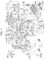
- FIG. 1 shows a communication structure that can be provided in the 6G system, based on an embodiment of the present disclosure.
- the embodiment of FIG. 1 may be combined with various embodiments of the present disclosure.
- 6G systems are expected to have 50 times higher simultaneous radio connectivity than 5G radio systems.
- URLLC a key feature of 5G, will become a more dominant technology in 6G communications, providing end-to-end delay of less than 1 ms.
- 6G systems will have much better volumetric spectral efficiency as opposed to the more commonly used area spectral efficiency. 6G systems will be able to offer very long battery life and advanced battery technologies for energy harvesting, so mobile devices will not need to be charged separately in a 6G system.
- New network characteristics in 6G may include the following.
- 5G NR is mainly described, but the technical idea according to an embodiment of the present disclosure is not limited thereto. Various embodiments of the present disclosure may also be applied to a 6G communication system.
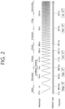
- FIG. 3 shows a structure of an NR system, based on an embodiment of the present disclosure.
- the embodiment of FIG. 3 may be combined with various embodiments of the present disclosure.
- a next generation-radio access network may include a BS 20 providing a UE 10 with a user plane and control plane protocol termination.
- the BS 20 may include a next generation-Node B (gNB) and/or an evolved-NodeB (eNB).
- the UE 10 may be fixed or mobile and may be referred to as other terms, such as a mobile station (MS), a user terminal (UT), a subscriber station (SS), a mobile terminal (MT), wireless device, and so on.
- the BS may be referred to as a fixed station which communicates with the UE 10 and may be referred to as other terms, such as a base transceiver system (BTS), an access point (AP), and so on.
- BTS base transceiver system
- AP access point
- the embodiment of FIG. 3 exemplifies a case where only the gNB is included.
- the BSs 20 may be connected to one another via Xn interface.
- the BS 20 may be connected to one another via 5th generation (5G) core network (5GC) and NG interface. More specifically, the BSs 20 may be connected to an access and mobility management function (AMF) 30 via NG-C interface, and may be connected to a user plane function (UPF) 30 via NG-U interface.
- 5G 5th generation
- GC 5th generation core network
- AMF access and mobility management function
- UPF user plane function
- Layers of a radio interface protocol between the UE and the network can be classified into a first layer (layer 1, L1), a second layer (layer 2, L2), and a third layer (layer 3, L3) based on the lower three layers of the open system interconnection (OSI) model that is well-known in the communication system.
- a physical (PHY) layer belonging to the first layer provides an information transfer service by using a physical channel
- a radio resource control (RRC) layer belonging to the third layer serves to control a radio resource between the UE and the network.
- the RRC layer exchanges an RRC message between the UE and the BS.
- FIG. 4 shows a radio protocol architecture, based on an embodiment of the present disclosure.
- the embodiment of FIG. 4 may be combined with various embodiments of the present disclosure.
- (a) of FIG. 4 shows a radio protocol stack of a user plane for Uu communication
- (b) of FIG. 4 shows a radio protocol stack of a control plane for Uu communication
- (c) of FIG. 4 shows a radio protocol stack of a user plane for SL communication
- (d) of FIG. 4 shows a radio protocol stack of a control plane for SL communication.
- a physical layer provides an upper layer with an information transfer service through a physical channel.
- the physical layer is connected to a medium access control (MAC) layer which is an upper layer of the physical layer through a transport channel.
- MAC medium access control
- Data is transferred between the MAC layer and the physical layer through the transport channel.
- the transport channel is classified according to how and with what characteristics data is transmitted through a radio interface.
- the physical channel is modulated using an orthogonal frequency division multiplexing (OFDM) scheme, and utilizes time and frequency as a radio resource.
- OFDM orthogonal frequency division multiplexing
- the MAC layer provides services to a radio link control (RLC) layer, which is a higher layer of the MAC layer, via a logical channel.
- RLC radio link control
- the MAC layer provides a function of mapping multiple logical channels to multiple transport channels.
- the MAC layer also provides a function of logical channel multiplexing by mapping multiple logical channels to a single transport channel.
- the MAC layer provides data transfer services over logical channels.
- the RLC layer performs concatenation, segmentation, and reassembly of Radio Link Control Service Data Unit (RLC SDU).
- RLC SDU Radio Link Control Service Data Unit
- TM transparent mode
- UM unacknowledged mode
- AM acknowledged mode
- An AM RLC provides error correction through an automatic repeat request (ARQ).
- a radio resource control (RRC) layer is defined only in the control plane.
- the RRC layer serves to control the logical channel, the transport channel, and the physical channel in association with configuration, reconfiguration and release of RBs.
- the RB is a logical path provided by the first layer (i.e., the physical layer or the PHY layer) and the second layer (i.e., a MAC layer, an RLC layer, a packet data convergence protocol (PDCP) layer, and a service data adaptation protocol (SDAP) layer) for data delivery between the UE and the network.
- the first layer i.e., the physical layer or the PHY layer
- the second layer i.e., a MAC layer, an RLC layer, a packet data convergence protocol (PDCP) layer, and a service data adaptation protocol (SDAP) layer
- Functions of a packet data convergence protocol (PDCP) layer in the user plane include user data delivery, header compression, and ciphering.
- Functions of a PDCP layer in the control plane include control-plane data delivery and ciphering/integrity protection.
- PDCP packet data convergence protocol
- SDAP service data adaptation protocol
- QoS Quality of Service
- DRB data radio bearer
- QFI QoS flow ID
- the configuration of the RB implies a process for specifying a radio protocol layer and channel properties to provide a particular service and for determining respective detailed parameters and operations.
- the RB can be classified into two types, i.e., a signaling RB (SRB) and a data RB (DRB).
- SRB signaling RB
- DRB data RB
- the SRB is used as a path for transmitting an RRC message in the control plane.
- the DRB is used as a path for transmitting user data in the user plane.
- an RRC_CONNECTED state When an RRC connection is established between an RRC layer of the UE and an RRC layer of the E-UTRAN, the UE is in an RRC_CONNECTED state, and, otherwise, the UE may be in an RRC_IDLE state.
- an RRC_INACTIVE state is additionally defined, and a UE being in the RRC_INACTIVE state may maintain its connection with a core network whereas its connection with the BS is released.
- Examples of logical channels belonging to a higher channel of the transport channel and mapped onto the transport channels include a broadcast channel (BCCH), a paging control channel (PCCH), a common control channel (CCCH), a multicast control channel (MCCH), a multicast traffic channel (MTCH), etc.
- BCCH broadcast channel
- PCCH paging control channel
- CCCH common control channel
- MCCH multicast control channel
- MTCH multicast traffic channel
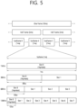
- FIG. 5 shows a structure of a radio frame of an NR, based on an embodiment of the present disclosure.
- the embodiment of FIG. 5 may be combined with various embodiments of the present disclosure.
- a radio frame may be used for performing uplink and downlink transmission.
- a radio frame has a length of 10ms and may be defined to be configured of two half-frames (HFs).
- a half-frame may include five 1ms subframes (SFs).
- a subframe (SF) may be divided into one or more slots, and the number of slots within a subframe may be determined based on subcarrier spacing (SCS).
- SCS subcarrier spacing
- Each slot may include 12 or 14 OFDM(A) symbols according to a cyclic prefix (CP).
- CP cyclic prefix
- each slot may include 14 symbols.
- each slot may include 12 symbols.
- a symbol may include an OFDM symbol (or CP-OFDM symbol) and a Single Carrier-FDMA (SC-FDMA) symbol (or Discrete Fourier Transform-spread-OFDM (DFT-s-OFDM) symbol).
- Table 2 shown below represents an example of a number of symbols per slot (N slot symb ), a number slots per frame (N frame,u slot ), and a number of slots per subframe (N subframe,u slot ) based on an SCS configuration (u), in a case where a normal CP or extened CP is used.
- OFDM(A) numerologies e.g., SCS, CP length, and so on
- a (absolute time) duration (or section) of a time resource e.g., subframe, slot or TTI
- a time unit (TU) for simplicity
- multiple numerologies or SCSs for supporting diverse 5G services may be supported.
- an SCS is 15kHz
- a wide area of the conventional cellular bands may be supported, and, in case an SCS is 30kHz/60kHz a dense-urban, lower latency, wider carrier bandwidth may be supported.
- the SCS is 60kHz or higher, a bandwidth that is greater than 24.25GHz may be used in order to overcome phase noise.
- An NR frequency band may be defined as two different types of frequency ranges.
- the two different types of frequency ranges may be FR1 and FR2.
- the values of the frequency ranges may be changed (or varied), and, for example, the two different types of frequency ranges may be as shown below in Table 3.
- FR1 may mean a "sub 6GHz range”
- FR2 may mean an "above 6GHz range” and may also be referred to as a millimeter wave (mmW).
- mmW millimeter wave
- FR1 may include a band within a range of 410MHz to 7125MHz. More specifically, FR1 may include a frequency band of 6GHz (or 5850, 5900, 5925 MHz, and so on) and higher. For example, a frequency band of 6GHz (or 5850, 5900, 5925 MHz, and so on) and higher being included in FR1 mat include an unlicensed band. The unlicensed band may be used for diverse purposes, e.g., the unlicensed band for vehicle-specific communication (e.g., automated driving).
- SCS Corresponding frequency range Subcarrier Spacing
- FIG. 6 shows a structure of a slot of an NR frame, based on an embodiment of the present disclosure.
- the embodiment of FIG. 6 may be combined with various embodiments of the present disclosure.
- a slot includes a plurality of symbols in a time domain.
- one slot may include 14 symbols.
- one slot may include 12 symbols.
- one slot may include 7 symbols.
- one slot may include 6 symbols.
- a carrier includes a plurality of subcarriers in a frequency domain.
- a Resource Block (RB) may be defined as a plurality of consecutive subcarriers (e.g., 12 subcarriers) in the frequency domain.
- a Bandwidth Part (BWP) may be defined as a plurality of consecutive (Physical) Resource Blocks ((P)RBs) in the frequency domain, and the BWP may correspond to one numerology (e.g., SCS, CP length, and so on).
- a carrier may include a maximum of N number BWPs (e.g., 5 BWPs). Data communication may be performed via an activated BWP.
- Each element may be referred to as a Resource Element (RE) within a resource grid and one complex symbol may be mapped to each element.
- RE Resource Element
- bandwidth part BWP
- carrier a bandwidth part (BWP) and a carrier
- the BWP may be a set of consecutive physical resource blocks (PRBs) in a given numerology.
- the PRB may be selected from consecutive sub-sets of common resource blocks (CRBs) for the given numerology on a given carrier
- the BWP may be at least any one of an active BWP, an initial BWP, and/or a default BWP.
- the UE may not monitor downlink radio link quality in a DL BWP other than an active DL BWP on a primary cell (PCell).
- the UE may not receive PDCCH, physical downlink shared channel (PDSCH), or channel state information - reference signal (CSI-RS) (excluding RRM) outside the active DL BWP.
- the UE may not trigger a channel state information (CSI) report for the inactive DL BWP.
- the UE may not transmit physical uplink control channel (PUCCH) or physical uplink shared channel (PUSCH) outside an active UL BWP.
- PUCCH physical uplink control channel
- PUSCH physical uplink shared channel
- the initial BWP may be given as a consecutive RB set for a remaining minimum system information (RMSI) control resource set (CORESET) (configured by physical broadcast channel (PBCH)).
- RMSI remaining minimum system information
- CORESET control resource set
- PBCH physical broadcast channel
- SIB system information block
- the default BWP may be configured by a higher layer.
- an initial value of the default BWP may be an initial DL BWP.
- DCI downlink control information
- the BWP may be defined for SL.
- the same SL BWP may be used in transmission and reception.
- a transmitting UE may transmit a SL channel or a SL signal on a specific BWP
- a receiving UE may receive the SL channel or the SL signal on the specific BWP.
- the SL BWP may be defined separately from a Uu BWP, and the SL BWP may have configuration signaling separate from the Uu BWP.
- the UE may receive a configuration for the SL BWP from the BS/network.
- the UE may receive a configuration for the Uu BWP from the BS/network.
- the SL BWP may be (pre-)configured in a carrier with respect to an out-of-coverage NR V2X UE and an RRC_IDLE UE. For the UE in the RRC_CONNECTED mode, at least one SL BWP may be activated in the carrier.
- FIG. 7 shows an example of a BWP, based on an embodiment of the present disclosure.
- the embodiment of FIG. 7 may be combined with various embodiments of the present disclosure. It is assumed in the embodiment of FIG. 7 that the number of BWPs is 3.
- a common resource block may be a carrier resource block numbered from one end of a carrier band to the other end thereof.
- the PRB may be a resource block numbered within each BWP.
- a point A may indicate a common reference point for a resource block grid.
- the BWP may be configured by a point A, an offset N start BWP from the point A, and a bandwidth N size BWF .
- the point A may be an external reference point of a PRB of a carrier in which a subcarrier 0 of all numerologies (e.g., all numerologies supported by a network on that carrier) is aligned.
- the offset may be a PRB interval between a lowest subcarrier and the point A in a given numerology.
- the bandwidth may be the number of PRBs in the given numerology.
- V2X or SL communication will be described.
- a sidelink synchronization signal may include a primary sidelink synchronization signal (PSSS) and a secondary sidelink synchronization signal (SSSS), as a SL-specific sequence.
- PSSS primary sidelink synchronization signal
- SSSS secondary sidelink synchronization signal
- the PSSS may be referred to as a sidelink primary synchronization signal (S-PSS)
- S-SSS sidelink secondary synchronization signal
- S-SSS sidelink secondary synchronization signal
- length-127 M-sequences may be used for the S-PSS
- length-127 gold sequences may be used for the S-SSS.
- a UE may use the S-PSS for initial signal detection and for synchronization acquisition.
- the UE may use the S-PSS and the S-SSS for acquisition of detailed synchronization and for detection of a synchronization signal ID.
- a physical sidelink broadcast channel may be a (broadcast) channel for transmitting default (system) information which must be first known by the UE before SL signal transmission/reception.
- the default information may be information related to SLSS, a duplex mode (DM), a time division duplex (TDD) uplink/downlink (UL/DL) configuration, information related to a resource pool, a type of an application related to the SLSS, a subframe offset, broadcast information, or the like.
- DM duplex mode
- TDD time division duplex
- UL/DL uplink/downlink
- a payload size of the PSBCH may be 56 bits including 24-bit cyclic redundancy check (CRC).
- the S-PSS, the S-SSS, and the PSBCH may be included in a block format (e.g., SL synchronization signal (SS)/PSBCH block, hereinafter, sidelink-synchronization signal block (S-SSB)) supporting periodical transmission.
- the S-SSB may have the same numerology (i.e., SCS and CP length) as a physical sidelink control channel (PSCCH)/physical sidelink shared channel (PSSCH) in a carrier, and a transmission bandwidth may exist within a (pre-)configured sidelink (SL) BWP.
- the S-SSB may have a bandwidth of 11 resource blocks (RBs).
- the PSBCH may exist across 11 RBs.
- a frequency position of the S-SSB may be (pre-)configured. Accordingly, the UE does not have to perform hypothesis detection at frequency to discover the S-SSB in the carrier.
- FIG. 8 shows a procedure of performing V2X or SL communication by a UE based on a transmission mode, based on an embodiment of the present disclosure.
- the transmission mode may be called a mode or a resource allocation mode.
- the transmission mode may be called an LTE transmission mode.
- the transmission mode may be called an NR resource allocation mode.
- (a) of FIG. 8 shows a UE operation related to an LTE transmission mode 1 or an LTE transmission mode 3.
- (a) of FIG. 8 shows a UE operation related to an NR resource allocation mode 1.
- the LTE transmission mode 1 may be applied to general SL communication
- the LTE transmission mode 3 may be applied to V2X communication.
- (b) of FIG. 8 shows a UE operation related to an LTE transmission mode 2 or an LTE transmission mode 4.
- (b) of FIG. 8 shows a UE operation related to an NR resource allocation mode 2.
- a base station may schedule SL resource(s) to be used by a UE for SL transmission.
- a base station may transmit information related to SL resource(s) and/or information related to UL resource(s) to a first UE.
- the UL resource(s) may include PUCCHresource(s) and/or PUSCH resource(s).
- the UL resource(s) may be resource(s) for reporting SL HARQ feedback to the base station.
- the first UE may receive information related to dynamic grant (DG) resource(s) and/or information related to configured grant (CG) resource(s) from the base station.
- the CG resource(s) may include CG type 1 resource(s) or CG type 2 resource(s).
- the DG resource(s) may be resource(s) configured/allocated by the base station to the first UE through a downlink control information (DCI).
- the CG resource(s) may be (periodic) resource(s) configured/allocated by the base station to the first UE through a DCI and/or an RRC message.
- the base station may transmit an RRC message including information related to CG resource(s) to the first UE.
- the base station may transmit an RRC message including information related to CG resource(s) to the first UE, and the base station may transmit a DCI related to activation or release of the CG resource(s) to the first UE.
- the first UE may transmit a PSCCH (e.g., sidelink control information (SCI) or 1 st -stage SCI) to a second UE based on the resource scheduling.
- a PSCCH e.g., sidelink control information (SCI) or 1 st -stage SCI
- the first UE may transmit a PSSCH (e.g., 2 nd -stage SCI, MAC PDU, data, etc.) related to the PSCCH to the second UE.
- the first UE may receive a PSFCH related to the PSCCH/PSSCH from the second UE.
- HARQ feedback information e.g., NACK information or ACK information
- the first UE may transmit/report HARQ feedback information to the base station through the PUCCH or the PUSCH.
- the HARQ feedback information reported to the base station may be information generated by the first UE based on the HARQ feedback information received from the second UE.
- the HARQ feedback information reported to the base station may be information generated by the first UE based on a pre-configured rule.
- the DCI may be a DCI for SL scheduling.
- a format of the DCI may be a DCI format 3_0 or a DCI format 3_1.
- DCI format 3_0 is used for scheduling of NR PSCCH and NR PSSCH in one cell.
- the following information is transmitted by means of the DCI format 3_0 with CRC scrambled by SL-RNTI or SL-CS-RNTI:
- a UE may determine SL transmission resource(s) within SL resource(s) configured by a base station/network or pre-configured SL resource(s).
- the configured SL resource(s) or the pre-configured SL resource(s) may be a resource pool.
- the UE may autonomously select or schedule resource(s) for SL transmission.
- the UE may perform SL communication by autonomously selecting resource(s) within the configured resource pool.
- the UE may autonomously select resource(s) within a selection window by performing a sensing procedure and a resource (re)selection procedure.
- the sensing may be performed in a unit of subchannel(s).
- a first UE which has selected resource(s) from a resource pool by itself may transmit a PSCCH (e.g., sidelink control information (SCI) or 1 st -stage SCI) to a second UE by using the resource(s).
- the first UE may transmit a PSSCH (e.g., 2 nd -stage SCI, MAC PDU, data, etc.) related to the PSCCH to the second UE.
- the first UE may receive a PSFCH related to the PSCCH/PSSCH from the second UE.
- the first UE may transmit a SCI to the second UE through the PSCCH.
- the first UE may transmit two consecutive SCIs (e.g., 2-stage SCI) to the second UE through the PSCCH and/or the PSSCH.
- the second UE may decode two consecutive SCIs (e.g., 2-stage SCI) to receive the PSSCH from the first UE.
- a SCI transmitted through a PSCCH may be referred to as a 1 st SCI, a first SCI, a 1 st -stage SCI or a 1 st -stage SCI format, and a SCI transmitted through a PSSCH may be referred to as a 2 nd SCI, a second SCI, a 2 nd -stage SCI or a 2 nd -stage SCI format.
- the 1 st -stage SCI format may include a SCI format 1-A
- the 2 nd -stage SCI format may include a SCI format 2-A and/or a SCI format 2-B.
- SCI format 1-A is used for the scheduling of PSSCH and 2 nd -stage-SCI on PSSCH.
- SCI format 2-A is used for the decoding of PSSCH, with HARQ operation when HARQ-ACK information includes ACK or NACK, when HARQ-ACK information includes only NACK, or when there is no feedback of HARQ-ACK information.
- SCI format 2-B is used for the decoding of PSSCH, with HARQ operation when HARQ-ACK information includes only NACK, or when there is no feedback of HARQ-ACK information.
- the first UE may receive the PSFCH.
- the first UE and the second UE may determine a PSFCH resource, and the second UE may transmit HARQ feedback to the first UE using the PSFCH resource.
- the first UE may transmit SL HARQ feedback to the base station through the PUCCH and/or the PUSCH.
- FIG. 9 shows three cast types, based on an embodiment of the present disclosure.
- the embodiment of FIG. 9 may be combined with various embodiments of the present disclosure.
- (a) of FIG. 9 shows broadcast-type SL communication
- (b) of FIG. 9 shows unicast type-SL communication
- (c) of FIG. 9 shows groupcast-type SL communication.
- a UE may perform one-to-one communication with respect to another UE.
- the UE may perform SL communication with respect to one or more UEs in a group to which the UE belongs.
- SL groupcast communication may be replaced with SL multicast communication, SL one-to-many communication, or the like.
- HARQ hybrid automatic repeat request
- the SL HARQ feedback may be enabled for unicast.
- a non-code block group non-CBG
- the receiving UE may generate HARQ-ACK.
- the receiving UE may transmit the HARQ-ACK to the transmitting UE.
- the receiving UE may transmit HARQ-NACK to the transmitting UE.
- the SL HARQ feedback may be enabled for groupcast.
- two HARQ feedback options may be supported for groupcast.
- all UEs performing groupcast communication may share a PSFCH resource.
- UEs belonging to the same group may transmit HARQ feedback by using the same PSFCH resource.
- each UE performing groupcast communication may use a different PSFCH resource for HARQ feedback transmission.
- UEs belonging to the same group may transmit HARQ feedback by using different PSFCH resources.
- HARQ-ACK may be referred to as ACK, ACK information, or positive-ACK information
- HARQ-NACK may be referred to as NACK, NACK information, or negative-ACK information.
- a TX UE and/or an RX UE may obtain a discontinuous reception (DRX) configuration.
- the DRX configuration may include a Uu DRX configuration and/or a SL DRX configuration.
- the TX UE may receive the DRX configuration from a base station, and the RX UE may receive the DRX configuration from the TX UE.
- the DRX configuration may be configured or pre-configured for the TX UE and/or the RX UE.
- the Uu DRX configuration may include information related to drx-HARQ-RTT-Timer-SL and/or information related to drx-RetransmissionTimer-SL.
- the timer may be used for the following purposes.
- the SL DRX configuration may include at least one parameter/information among parameters/information described below.
- the SL DRX timer described in the present disclosure may be used for the following purposes.
- the UE may extend the SL DRX onduration timer by the SL DRX inactivity timer duration.
- the UE may extend the SL DRX onduration timer by starting the SL DRX inactivity timer.
- the SL DRX inactivity timer may be used for extending the SL DRX onduration duration, which is the duration in which the RX UE performing the SL DRX operation should basically operate in the active time in order to receive the PSCCH/PSSCH from other UE(s). That is, the SL DRX onduration timer may be extended by the SL DRX inactivity timer period.
- the RX UE may extend the SL DRX onduration timer by starting the SL DRX inactivity timer.
- SL DRX HARQ RTT timer the duration in which the UE performing the SL DRX operation operates in a sleep mode until receiving a retransmission packet (or PSSCH assignment) transmitted by other UE(s)
- the UE may determine that other UE(s) will not transmit a sidelink retransmission packet to the UE until the SL DRX HARQ RTT timer expires, and the UE may operate in a sleep mode while the corresponding timer is running. For example, if the UE starts the SL DRX HARQ RTT timer, the UE may not monitor a sidelink retransmission packet from other UE(s) until the SL DRX HARQ RTT timer expires.
- the RX UE may start the SL DRX HARQ RTT timer.
- the RX UE may determine that other TX UE(s) will not transmit a sidelink retransmission packet to the RX UE until the SL DRX HARQ RTT timer expires, and the RX UE may operate in a sleep mode while the corresponding timer is running.
- SL DRX retransmission timer the timer which starts when the SL DRX HARQ RTT timer expires, and the duration in which the UE performing the SL DRX operation operates in an active time in order to receive a retransmission packet (or PSSCH assignment) transmitted by other UE(s)
- the UE may receive or monitor a retransmission sidelink packet (or PSSCH assignment) transmitted by other UE(s).
- the RX UE may receive or monitor a retransmission sidelink packet (or PSSCH assignment) transmitted by other TX UE(s) while the SL DRX retransmission timer is running.
- a UE operating in sidelink DRX may operate in active mode during DRX active time (e.g., onduration timer, inactivity timer, retransmission timer, or duration when operating in active mode) to perform PSCCH/PSSCH monitoring.
- DRX active time e.g., onduration timer, inactivity timer, retransmission timer, or duration when operating in active mode
- the UE may operate in sleep mode during the sidelink DRX inactive time duration and not perform PSCCH/PSSCH monitoring operations for SL data reception.
- a UE may negotiate/determine the sidelink DRX configuration (SL DRX configuration to be used during sidelink unicast communication) with the other UE with which it has established a unicast connection. If there is a connection (RRC connection) between the transmission UE and the base station, the base station of the transmission UE may configure the SL DRX configuration to be used by the reception UE that has established a unicast connection with the transmission UE and inform the transmission UE, and the transmission UE may transmit the SL DRX configuration to be used by the reception UE received from the base station to the reception UE through a PC5 RRC message.
- RRC connection connection
- the transmission UE may configure the SL DRX configuration to be used by the reception UE that has established a unicast connection with the transmission UE directly and transmit it to the reception UE through a PC5 RRC message.
- the transmission UE While SL DRX is an operation for the reception UE, the transmission UE also needs to know the SL DRX operation status of the reception UE (active or sleep mode, or when the DRX onduration/inactivity/HARQ RTT/retransmission timer starts, when the DRX onduration/inactivity/HARQ RTT/retransmission timer expires, etc). For example, when allocating and transferring resources, the transmission UE should be able to determine whether the reception UE is operating in active mode or sleep mode. Therefore, the transmission UE may apply the same SL DRX configuration as the reception UE to maintain the same operation state of the SL DRX timer, etc. as the reception UE.
- the AS layer of a UE (RX UE or TX UE) supporting SL DRX behavior may receive a Tx profile mapped for an available sidelink service from a higher layer (e.g., V2X layer).
- the Tx profile may include information distinguishing whether an available sidelink service or an interested sidelink service is a sidelink service that needs to perform SL DRX operation. Therefore, when the AS layer of a UE receives the available sidelink data (or the interested sidelink service) and Tx profile from the upper layer, the UE may decide (or determine) that it should or should not support SL DRX operation for the available sidelink data (or the interested sidelink service).
- NR-U unlicensed spectrum
- a communication method between a UE and a base station is supported in an unlicensed band.
- a mechanism for supporting communication in an unlicensed band between sidelink UEs is planned to be supported in Rel-18.
- a set of non-contiguous RBs (equally spaced) on the frequency may be allocated to the UE.
- a set of such non-contiguous RBs may be referred to as an interlaced RB. This may be useful in spectrum (eg, shared spectrum) where regulations such as occupied channel bandwidth (OCB) and power spectral density (PSD) are applied.
- spectrum eg, shared spectrum
- OCB occupied channel bandwidth
- PSD power spectral density
- FIG. 10 shows interlaced RB, based on an embodiment of the present disclosure.
- the embodiment of FIG. 110 may be combined with various embodiments of the present disclosure.
- interlaces of RBs may be defined in the frequency domain.
- An interlace m ⁇ ⁇ 0, 1, ..., M-1 ⁇ may consist of the (common) RBs ⁇ m, M+m, 2M+m, 3M+m, ... ⁇ , where M denotes the number of interlaced RBs given by Table 8. [Table 8] u M 0 10 1 5
- a communication device may use one or more interlaced RBs to transmit a signal/channel.
- a channel may refer to a set of frequency domain resources in which Listen-Before-Talk (LBT) is performed.
- LBT Listen-Before-Talk
- the channel may refer to an LBT bandwidth with 20 MHz and may have the same meaning as an RB set.
- the RB set may be defined in section 7 of 3GPP TS 38.214 V17.0.0.
- channel occupancy may refer to time/frequency domain resources obtained by the base station or the UE after LBT success.
- channel occupancy time may refer to time domain resources obtained by the base station or the UE after LBT success. It may be shared between the base station (or the UE) and the UE (or the base station) that obtained the CO, and this may be referred to as COT sharing. Depending on the initiating device, this may be referred to as gNB-initiated COT or UE-initiated COT.
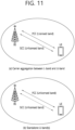
- FIG. 11 shows an example of a wireless communication system supporting an unlicensed band, based on an embodiment of the present disclosure.
- FIG. 11 may include an unlicensed spectrum (NR-U) wireless communication system.
- NR-U unlicensed spectrum
- the embodiment of FIG. 11 may be combined with various embodiments of the present disclosure.
- a cell operating in a licensed band may be defined as an L-cell, and a carrier of the L-cell may be defined as a (DL/UL/SL) LCC.
- a cell operating in an unlicensed band hereinafter, U-band
- U-band may be defined as a U-cell
- a carrier of the U-cell may be defined as a (DL/UL/SL) UCC.
- the carrier/carrier-frequency of a cell may refer to the operating frequency (e.g., center frequency) of the cell.
- a cell/carrier e.g., CC
- a cell/carrier is commonly called a cell.
- the LCC and the UCC may be configured as a primary CC (PCC) and a secondary CC (SCC), respectively.
- the base station and the UE may transmit and receive signals on one UCC or on a plurality of carrier-aggregated UCCs as shown in (b) of FIG. 11 .
- the base station and the UE may transmit and receive signals only on UCC(s) without using any LCC.
- PRACH transmission, PUCCH transmission, PUSCH transmission, SRS transmission, etc. may be supported on a UCell.
- the base station may be replaced with the UE.
- PSCCH transmission, PSSCH transmission, PSFCH transmission, S-SSB transmission, etc. may be supported on a UCell.
- FIG. 12 shows a method of occupying resources in an unlicensed band, based on an embodiment of the present disclosure.
- the embodiment of FIG. 12 may be combined with various embodiments of the present disclosure.
- a communication node within an unlicensed band should determine whether other communication node(s) is using a channel before signal transmission.
- the communication node within the unlicensed band may perform a channel access procedure (CAP) to access channel(s) on which transmission(s) is performed.
- the channel access procedure may be performed based on sensing.
- the communication node may perform carrier sensing (CS) before transmitting signals so as to check whether other communication node(s) perform signal transmission.
- CS carrier sensing
- a CCA threshold e.g., X Thresh
- a higher layer e.g., RRC
- the communication node may determine that the channel is busy if the detected channel energy is higher than the CCA threshold. Otherwise, the communication node may determine that the channel is idle. If it is determined that the channel is idle, the communication node may start the signal transmission in the unlicensed band.
- the CAP may be replaced with the LBT.
- Table 9 shows an example of the channel access procedure (CAP) supported in NR-U.
- Type Explanation DL Type 1 CAP CAP with random back-off - time duration spanned by the sensing slots that are sensed to be idle before a downlink transmission(s) is random Type 2 CAP CAP without random back-off - Type 2A, 2B, 2C - time duration spanned by sensing slots that are sensed to be idle before a downlink transmission(s) is deterministic UL or SL
- the LBT type or CAP for DL/UL/SL transmission may be defined.
- Table 9 is only an example, and a new type or CAP may be defined in a similar manner.
- the type 1 also referred to as Cat-4 LBT
- the contention window may change.
- the type 2 can be performed in case of COT sharing within COT acquired by the base station (gNB) or the UE.
- one cell (or carrier (e.g., CC)) or BWP configured for the UE may have a wideband having a larger bandwidth (BW) than in legacy LTE.
- BW bandwidth
- a BW requiring CCA based on an independent LBT operation may be limited according to regulations.
- a subband (SB) in which LBT is individually performed be defined as an LBT-SB.
- a plurality of LBT-SBs may be included in one wideband cell/BWP.
- a set of RBs included in an LBT-SB may be configured by higher-layer (e.g., RRC) signaling.
- one or more LBT-SBs may be included in one cell/BWP based on (i) the BW of the cell/BWP and (ii) RB set allocation information.
- FIG. 13 shows a case in which a plurality of LBT-SBs are included in an unlicensed band, based on an embodiment of the present disclosure.
- the embodiment of FIG. 13 may be combined with various embodiments of the present disclosure.
- a plurality of LBT-SBs may be included in the BWP of a cell (or carrier).
- An LBT-SB may have, for example, a 20-MHz band.
- the LBT-SB may include a plurality of contiguous (P)RBs in the frequency domain, and thus may be referred to as a (P)RB set.
- a guard band (GB) may be interposed between LBT-SBs.
- the BWP may be configured in the form of ⁇ LBT-SB #0 (RB set #0)+GB #0+LBT-SB #1 (RB set #1+GB #1) + ... +LBT-SB #(K-1) (RB set (#K-1)) ⁇ .
- LBT-SB/RB indexes may be configured/defined in an increasing order from the lowest frequency to the highest frequency.
- CAC channel access priority class
- the CAPCs of MAC CEs and radio bearers may be fixed or configured to operate in FR1:
- the base station When selecting a CAPC of a DRB, the base station considers fairness between other traffic types and transmissions while considering 5QI of all QoS flows multiplexed to the corresponding DRB.
- Table 10 shows which CAPC should be used for standardized 5QI, that is, a CAPC to be used for a given QoS flow.
- CAPCs are defined as shown in the table below, and for non-standardized 5QI, the CAPC with the best QoS characteristics should be used.
- a method of transmitting a downlink signal through an unlicensed band will be described.
- a method of transmitting a downlink signal through an unlicensed band may be applied to a method of transmitting a sidelink signal through an unlicensed band.
- the base station may perform one of the following channel access procedures (e.g., CAP) for downlink signal transmission in an unlicensed band.
- CAP channel access procedures
- the length of a time duration spanned by sensing slots sensed to be idle before transmission(s) may be random.
- the type 1 DL CAP may be applied to the following transmissions:
- FIG. 14 shows CAP operations performed by a base station to transmit a downlink signal through an unlicensed band, based on an embodiment of the present disclosure.
- the embodiment of FIG. 14 may be combined with various embodiments of the present disclosure.
- the base station may sense whether a channel is idle for sensing slot durations of a defer duration Td. Then, if a counter N is zero, the base station may perform transmission (S134). In this case, the base station may adjust the counter N by sensing the channel for additional sensing slot duration(s) according to the following steps:
- Step 3) The base station senses the channel for the additional sensing slot duration. If the additional sensing slot duration is idle (Y), step 4 proceeds. Otherwise (N), step 5 proceeds.
- Step 5 The base station senses the channel until either a busy sensing slot is detected within an additional defer duration T d or all the slots of the additional defer duration T d are detected to be idle.
- Step 6 If the channel is sensed to be idle for all the slot durations of the additional defer duration Td (Y), step 4 proceeds. Otherwise (N), step 5 proceeds.
- Table 11 shows that m p , a minimum contention window (CW), a maximum CW, a maximum channel occupancy time (MCOT), and an allowed CW size, which are applied to the CAP, vary depending on channel access priority classes.
- Channel Access Priority Class (p) m p CW min,p CW max,p T mcot,p allowed CW p sizes 1 1 3 7 2 ms ⁇ 3,7 ⁇ 2 1 7 15 3 ms ⁇ 7,15 ⁇ 3 3 15 63 8 or 10 ms ⁇ 15,31,63 ⁇ 4 7 15 1023 8 or 10 ms ⁇ 15,31,63,127,255,511,1023 ⁇
- a contention window size (CWS), a maximum COT value, etc. for each CAPC may be defined.
- the defer duration T d is configured in the following order: duration T f (16 us) + mp consecutive sensing slot durations T sl (9 us).
- T f includes the sensing slot duration T sl at the beginning of the 16 us duration.
- HARQ-ACK feedback e.g., the ratio of ACK or NACK
- CW p may be initialized to CW min,p based on the HARQ-ACK feedback for the previous DL burst.
- CW p may be increased to the next higher allowed value or maintained as it is.
- the length of a time duration spanned by sensing slots sensed to be idle before transmission(s) may be determined.
- the type 2 DL CAP is classified into type 2A/2B/2C DL CAPs.
- the type 2A DL CAP may be applied to the following transmissions.
- the type 2B DL CAP is applicable to transmission(s) performed by the base station after a gap of 16 us from transmission(s) by the UE within a shared channel occupancy time.
- T f includes a sensing slot within 9 us from the end of the duration.
- the type 2C DL CAP is applicable to transmission(s) performed by the base station after a maximum of 16 us from transmission(s) by the UE within the shared channel occupancy time. In the type 2C DL CAP, the base station does not perform channel sensing before performing transmission.
- a method of transmitting an uplink signal through an unlicensed band will be described.
- a method of transmitting an uplink signal through an unlicensed band may be applied to a method of transmitting a sidelink signal through an unlicensed band.
- the length of a time duration spanned by sensing slots sensed to be idle before transmission(s) is random.
- the type 1 UL CAP may be applied to the following transmissions.
- FIG. 15 shows type 1 CAP operations performed by a UE to transmit an uplink signal, based on an embodiment of the present disclosure.
- the embodiment of FIG. 15 may be combined with various embodiments of the present disclosure.
- the UE may sense whether a channel is idle for sensing slot durations of a defer duration T d . Then, if a counter N is zero, the UE may perform transmission (S234). In this case, the UE may adjust the counter N by sensing the channel for additional sensing slot duration(s) according to the following steps:
- Step 3) The UE senses the channel for the additional sensing slot duration. If the additional sensing slot duration is idle (Y), step 4 proceeds. Otherwise (N), step 5 proceeds.
- Step 5 The UE senses the channel until either a busy sensing slot is detected within an additional defer duration T d or all the slots of the additional defer duration T d are detected to be idle.
- Step 6 If the channel is sensed to be idle for all the slot durations of the additional defer duration Td (Y), step 4 proceeds. Otherwise (N), step 5 proceeds.
- Table 12 shows that m p , a minimum CW, a maximum CW, a maximum channel occupancy time (MCOT), and an allowed CW size, which are applied to the CAP, vary depending on channel access priority classes.
- Channel Access Priority Class (p) m p CW min,p CW max,p T ulmcot,p allowed CW p sizes 1 2 3 7 2ms ⁇ 3,7 ⁇ 2 2 7 15 4ms ⁇ 7,15 ⁇ 3 3 15 1023 6 or 10 ms ⁇ 15,31,63,127,255,511,1023 ⁇ 4 7 15 1023 6 or 10 ms ⁇ 15,31,63,127,255,511,1023 ⁇ 4 7 15 1023 6 or 10 ms ⁇ 15,31,63,127,255,511,1023 ⁇
- a contention window size (CWS), a maximum COT value, etc. for each CAPC may be defined.
- the defer duration Td is configured in the following order: duration T f (16 us) + mp consecutive sensing slot durations T sl (9 us).
- T f includes the sensing slot duration T sl at the beginning of the 16 us duration.
- CW p may be initialized to CW min,p based on the explicit/implicit reception response for the previous UL burst.
- CW p may be increased to the next higher allowed value or maintained as it is.
- the length of a time duration spanned by sensing slots sensed to be idle before transmission(s) may be determined.
- the type 2 UL CAP is classified into type 2A/2B/2C UL CAPs.
- T f includes a sensing slot at the beginning thereof.
- T f includes a sensing slot within 9 us from the end of the duration.
- the UE does not perform channel sensing before performing transmission.
- the UE having uplink data to be transmitted may select a CAPC mapped to 5QI of data, and the UE may perform the NR-U operation by applying parameters of the corresponding CACP (e.g., minimum contention window size, maximum contention window size, m p , etc.).
- the UE may select a backoff counter (BC) after selecting a random value between 0 and CW (e.g., the minimum CW and the maximum CW mapped to the CAPC).
- the BC may be a positive integer less than or equal to the random value.
- the UE may attempt to transmit data by occupying the channel. For example, if the UE detects a collision when it attempts to transmit data, it may increase the contention window size (CW size) mapped to the CAPC. In addition, the UE may reselect a random value for the backoff count between 0 and CW which is reselected through the increased CW. For example, if the UE succeeds in packet transmission, the contention window (CW size) may be initialized to a default value mapped to the initial CAPC.
- m p may be a constant mapped per CAPC and be used for calculating the T d .
- m p may be mapped to smaller values as the CAPC value decrease (or the priority increases).
- the UE may transmit data by performing the type 2 LBT (e.g., type 2A LBT, type 2B LBT, or type 2C LBT) within COT.
- type 2 LBT e.g., type 2A LBT, type 2B LBT, or type 2C LBT
- the type 2A (also referred to as Cat-2 LBT (one shot LBT) or one-shot LBT) may be 25 usec one-shot LBT. In this case, transmission may start immediately after idle sensing for at least a 25 usec gap.
- the type 2A may be used to initiate transmission of SSB and non-unicast DL information. That is, the UE may sense a channel for 25 usec within COT, and if the channel is idle, the UE may attempt to transmit data by occupying the channel.
- the type 2B may be 16 usec one-shot LBT.
- transmission may start immediately after idle sensing for a 16 usec gap. That is, the UE may sense a channel for 16 usec within COT, and if the channel is idle, the UE may attempt to transmit data by occupying the channel.
- LBT may not be performed.
- transmission may start immediately after a gap of up to 16 usec and a channel may not be sensed before the transmission.
- the duration of the transmission may be up to 584 usec.
- the UE may attempt transmission after 16 usec without sensing, and the UE may perform transmission for up to 584 usec.
- the UE may perform a channel access operation based on Listen Before Talk (LBT). Before the UE accesses a channel in an unlicensed band, the UE should check whether the channel to be accessed is idle (e.g., a state in which UEs do not occupy the channel, a state in which UEs can access the corresponding channel and transmit data) or busy (e.g., a state in which the channel is occupied and data transmission/reception is performed on the corresponding channel, and the UE attempting to access the channel cannot transmit data while the channel is busy). That is, the operation in which the UE checks whether the channel is idle or busy may be referred to as Clear Channel Assessment (CCA), and the UE may check whether the channel is idle or busy for the CCA duration.
- CCA Clear Channel Assessment
- FIG. 16 shows a channel access procedure, based on an embodiment of the present disclosure. Specifically, (a) of FIG. 16 shows an example of a dynamic channel access procedure (load based equipment, LBE), and (b) of FIG. 16 shows an example of a semi-static channel access procedure (frame based equipment, FBE).
- LBE load based equipment
- FBE frame based equipment
- the UE may perform contention with other UEs on an unlicensed band to immediately occupy the channel. In addition, if the UE occupies the channel, the UE may transmit data.
- the UE may perform contention with other UEs on an unlicensed band at the last time within a synchronized frame boundary (or a fixed frame period (FFP)) (e.g., certain time before the start of the next FFP (or starting time)).
- FFP fixed frame period
- the UE may transmit data. The data transmission should complete before the next FFP begins.
- the UE may perform sidelink (SL) transmission by performing LBT for each resource block (RB) set in the sidelink-unlicensed spectrum (SL-U) and may report LBT failure to the base station when LBT is failed.
- the counterpart UE may unnecessarily perform resource selection even for the RB set that failed the LBT, which may cause unnecessary power consumption of the counterpart UE or unnecessary delay in communication in the SL-U.
- radio link failure may occur when transmission fails due to channel quality degradation or unstable conditions, but in unlicensed bands, transmission may fail due to LBT failure regardless of the channel quality, so if the value of the DTX count is increased only due to transmission failure, RLF operation may be performed unnecessarily even if the channel condition is good.
- the UE in order to transmit SL data, the UE should first occupy a channel in the SL-U. For example, in order to occupy the channel in the SL-U, the UE may perform a procedure to find a channel not occupied by neighboring sidelink UEs by performing the LBT (e.g., type 1 LBT: random backoff-based LBT). For example, when the UE performing LBT finds the channel not occupied by different UEs, it may occupy the channel and perform SL data transmission.
- LBT type 1 LBT: random backoff-based LBT
- operations of UE when the LBT e.g., one shot LBT failure or consistent LBT failure (when LBT failure indication is received from the physical (PHY) layer as many as the threshold)
- LBT e.g., one shot LBT failure or consistent LBT failure (when LBT failure indication is received from the physical (PHY) layer as many as the threshold)
- the UE may transmit the sidelink data to the destination UE by including the data to a sidelink grant.
- the UE may report one shot LBT failure report or consistent LBT failure report to the counterpart UE (e.g., a destination UE that has established an unicast connection, a destination UE that has established a RRC connection, or a destination UE receiving groupcast/broadcast message).
- the counterpart UE e.g., a destination UE that has established an unicast connection, a destination UE that has established a RRC connection, or a destination UE receiving groupcast/broadcast message.
- the UE reporting one shot LBT failure report or consistent LBT failure report may transmit the LBT failure report message to the counterpart UE through the SCI or MAC CE or PC5 RRC message.
- the LBT failure report message through the MAC CE or the PC5 RRC message may be transmitted in unicast (including source layer 2 ID and destination layer 2 ID in the message) or groupcast/groupcast (including groupcast/broadcast destination layer 2 ID in the message) manners.
- the LBT failure report message through the SCI may be transmitted in unicast (including source layer 1 ID and destination layer 1 ID in the message) or groupcast/groupcast (including groupcast/broadcast destination layer 1 ID in the message) manners.
- information about the number of times a LBT failure has occurred may be included in the consistent LBT failure report message.
- the UE receiving the one shot LBT failure report or the consistent LBT failure report message may perform the LBT by applying the SL-CAPC (e.g., the SL-CAPC with greater SL-CAPC value) of lower priority class than the SL-CAPC currently applied.
- the SL-CAPC e.g., the SL-CAPC with smaller SL-CAPC value
- the SL-CAPC e.g., the SL-CAPC with smaller SL-CAPC value
- the UE receiving the one shot LBT failure report or the consistent LBT failure report message may perform the LBT and transmission operation by using different resource pool or different RB set other than resource pool or RB set currently used.
- the UE receiving the one shot LBT failure report or the consistent LBT failure report message may transfer the one shot LBT failure report or the consistent LBT failure report to its serving base station (for example, it may be transferred by the sidelink UE information or the UE assistance information or the LBT failure report MAC CE to indicate sidelink LBT failure).
- the UE transmitting the one shot LBT failure report or the consistent LBT failure report message may perform the LBT by applying the SL-CAPC (e.g., the SL-CAPC with greater SL-CAPC value) of lower priority class than the SL-CAPC currently applied.
- the UE transmitting the one shot LBT failure report or the consistent LBT failure report message also performs a role of transmission UE, it may perform the LBT by applying the SL-CAPC (e.g., the SL-CAPC with smaller SL-CAPC value) of higher priority class than the SL-CAPC currently applied.
- the UE transmitting the one shot LBT failure report or the consistent LBT failure report message also performs a role of transmission UE, it may perform the LBT and transmission operation by using different RB set other than RB set currently used.
- the UE declaring one shot LBT failure or consistent LBT failure may transmit the one shot LBT failure report or the consistent LBT failure report message to the counterpart UE by using different resource pool or different RB set other than resource pool or RB set currently used (for example, it may be transmitted through SCI or MAC CE or PC5 RRC message).
- the proposed operation may increase the probability of successful reception of the LBT failure report message by the reception UE.
- the reception UE may use it as information for the purpose of maintaining the current sidelink session (e.g., unicast or groupcast or broadcast).
- the reception UE may use it as information for the purpose such as early releases of the current sidelink session (e.g., unicast or groupcast or broadcast).
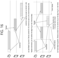
- FIG. 17 shows an operation of the UE transmitting LBT failure report message to the counterpart UE, based on an embodiment of the present disclosure.
- the embodiment of FIG. 17 may be combined with various embodiments of the present disclosure.
- UE A and UE B may obtain information related to a plurality of RB sets.
- the UE A may establish unicast connection or PC5 RRC connection with the UE B.
- the UE A may perform the LBT for each of the plurality of RB sets.
- configuration related to the LBT may be independently configured for each of the plurality of RB sets.
- the configuration related to the LBT may be LBT failure recovery configuration.
- the LBT failure recovery configuration may include information related to LBT counter or information related to LBT failure instance max count.
- the LBT may be a type 1 LBT (e.g., random backoff-based LBT).
- the LBT may be an one shot LBT or a consistent LBT.
- the UE A may perform LBT for a first RB set and a second RB set included in the plurality of RB sets, respectively.
- a first LBT failure recovery configuration may be configured to the first RB set, and the first LBT failure recovery configuration may include information related to a first LBT counter or information related to a first LBT failure instance max count.
- the UE A may fail to the LBT for the first RB set. For example, when the LBT is the consistent LBT, a value of the first LBT counter for the first RB set may be incremented whenever the LBT failure indication is transferred from the lower layer to the higher layer.
- the UE A may transmit LBT failure reporting information to the UE B (counterpart UE B) other than the base station.
- the UE A may include information for the first RB set in the LBT failure reporting information.
- the UE A may transmit LBT failure reporting information related to the first RB set on the second RB set to the UE B, based on LBT success for the second RB set.
- the LBT failure reporting information may be transmitted through SCI, MAC CE, or PC5 RRC message.
- the UE B receiving the LBT failure reporting information may perform the LBT for different RB set excluding the first RB set, based on information related to the first RB set included in the LBT failure reporting information.
- the UE B receiving the LBT failure reporting information may perform resource selection on resources excluding the first RB set (or, RB sets excluding the first RB set), based on information related to the first RB set included in the LBT failure reporting information.
- the LBT failure counting for consistent LBT failure declaration of physical sidelink feedback channel (PSFCH) transmission may be performed independently by the UE.
- the LBT failure counting for consistent LBT failure declaration of physical sidelink control channel/physical sidelink shared channel (PSCCH/PSSCH) for sidelink data transmission may be performed independently by the UE.
- the operation of the consistent LBT failure declaration may be differently defined depending on the type of message.
- the sl-lbt-FailureInstanceMaxCount for the consistent LBT failure declaration of PSCCH/PSSCH for the sidelink data transmission may be configured to be a greater value than the sl-lbt-FailureInstanceMaxCount for the consistent LBT failure declaration of PSFCH transmission or the sl-lbt-FailureInstanceMaxCount for the consistent LBT failure declaration of sidelink SSB transmission.
- the sl-lbt-FailureInstanceMaxCount for the consistent LBT failure declaration of PSCCH/PSSCH for the sidelink data transmission may be configured to be a smaller value than the sl-lbt-FailureInstanceMaxCount for the consistent LBT failure declaration of PSFCH transmission or the sl-lbt-FailureInstanceMaxCount for the consistent LBT failure declaration of sidelink SSB transmission.
- the transmission UE when the transmission UE transmits HARQ feedback enabled MAC CE (e.g., PSCCH or PSSCH) to the reception UE and does not receive HARQ feedback from the reception UE, it may consider the transmission as a discontinuous transmission (DTX) and increment numConsecutiveDTX by 1.
- DTX discontinuous transmission
- numConsecutiveDTX a discontinuous transmission
- it may consider the retransmission as a DTX again and increment the numConsecutiveDTX by 1.
- the transmission UE may declare the sidelink radio link failure (RLF) and may release the PC5 RRC connection that RLF occurs, and may report an occurrence of the sidelink RLF to the base station.
- RLF radio link failure
- the transmission UE fails to transmit sidelink data (e.g., PSCCH or PSSC) due to the LBT failure, it may not be considered as channel quality degradation condition, which is the same as a DTX occurrence. For example, even if the channel condition is good, the LBT may fail if the channel is occupied by another UE.
- sidelink data e.g., PSCCH or PSSC
- the transmission UE may reduce probability of RLF declaration by deducting the number of times the transmission UE failed to transmit PSFCH (e.g., HARQ feedback) due to the LBT failure from the number of numConsecutiveDTX counts that the transmission UE incremented by considering it as DTX. For example, when the transmission UE obtains channel state information (or, channel busy ratio (CBR)), the transmission UE may detect whether the failure of the reception UE to transmit HARQ feedback is due to poor channel condition or whether the reception UE failed to LBT for the channel even though the channel condition is good.
- CBR channel busy ratio
- the transmission UE may detect whether the failure of the reception UE to transmit HARQ feedback is due to poor channel condition or whether the reception UE failed to LBT for the channel even though the channel condition is good.
- the transmission UE may detect that the failure of HARQ feedback transmission of the reception UE is due to the LBT failure of the reception UE, regardless of the channel condition.
- operation for performing LBT counting independently for PSCCH/PSSCH, PSFCH, or SL-SSB and independently declaring consistent LBT failure is proposed.
- the transmission UE may decrement the DTX count (e.g., numConsecutiveDTX) by sl-lbt-FailureInstanceMaxCount for the consistent LBT failure report of the PSFCH. Therefore, for example, since the transmission UE may decrement the DTX count, the transmission UE may not include a case in which the PSFCH is not received due to the LBT failure in the RLF declaration operation.
- the DTX count e.g., numConsecutiveDTX
- a method to set sl-lbt-FailureInstanceMaxCount for PSFCH to a smaller value than sl-maxNumConsecutiveDTX is proposed.
- the transmission UE when the transmission UE declares the LBT failure in the current resource pool or the current RB set, instead of immediately declaring the SL RLF, it may continue sidelink transmission and reception operations in the unlicensed band by switching to a different resource pool or a different RB set.
- the transmission UE may inform the reception UE in advance, through MAC CE or PC5 RRC message or SCI, of which resource pool or which RB set to switch to when the consistent LBT failure occurs (or pre-configured, or receive information of threshold N from the base station).
- the transmission UE when the transmission UE declares the consistent LBT failure for multiple (e.g., threshold number) of resource pools or multiple (e.g., threshold number) of RB sets, if the operation declaring the SL RLF is supported, the transmission UE may inform in advance (e.g., when establishing a unicast connection or when performing PC5 RRC reconfiguration process, etc.), through MAC CE or PC5 RRC message or SCI, information of threshold N (e.g., threshold N resource pools, or when the SL RLF consistent LBT failure occurs in the threshold N RB sets and the SL RLF is declared, resource pools determined to declare the SL RLF, or the threshold N number of consistent LBT failure occurring in the RB set) to the reception UE (or pre-configured, or receive information of threshold N from the base station).
- threshold N e.g., threshold N resource pools, or when the SL RLF consistent LBT failure occurs in the threshold N RB sets and the SL RLF is declared, resource pools determined to declare the
- FIG. 18 shows an operation related to PSFCH transmission failure due to LBT failure by the UE, based on an embodiment of the present disclosure.
- the embodiment of FIG. 18 may be combined with various embodiments of the present disclosure.
- the UE A may transmit PSSCH to the UE B.
- the UE A may perform the PSSCH transmission on the RB set where the LBT is succeed.
- the UE B may perform LBT to transmit feedback (PSFCH) for the PSSCH to the UE A.
- the UE B may fail the LBT for the PSFCH transmission.
- the UE B may fail to PSFCH transmission.
- the UE may fail to the PSFCH transmission because the channel condition is poor. For example, even if the channel condition is good, the UE B may fail to the PSFCH transmission because the channel is occupied by another UE.
- the UE B may fail to the PSFCH transmission because the LBT fails.
- the UE A may determine whether the PSFCH reception failure (or the PSFCH transmission failure of the UE B) is due to the LBT failure. For example, the UE A may determine whether the PSFCH reception failure (or the PSFCH transmission failure of the UE B) is due to a poor channel condition, or whether the UE B fails the LBT even though the channel condition is good. For example, if the UE A obtains channel state information (e.g., CBR information), the UE A may detect whether the PSFCH reception failure is due to the poor channel condition, or whether the UE B fails the LBT even though the channel is good.
- channel state information e.g., CBR information
- the UE A may detect whether the PSFCH reception failure is due to the poor channel condition, or whether the UE B fails the LBT even though the channel is good. For example, if the UE A receives LBT failure reporting information from the UE B, the UE A may detect that the PSFCH reception failure is due to the LBT failure of the UE B. In step S1850, the UE A may not increment the DTX count based on the determination that the PSFCH reception failure is due to the LBT failure of the UE B.
- channel state information e.g., CSI
- the UE A may obtain information related to LBT failure max count for the PSFCH included in the LBT failure reporting information, and the UE A may not increment the DTX count by the LBT failure instance max count for the PSFCH.
- the transmission UE performing sidelink communication in the sidelink unlicensed band may perform sidelink LBT operation (or consistent SL LBT failure operation) for each unicast link to occupy the channel of the sidelink unlicensed band.
- sidelink LBT operation or consistent SL LBT failure operation
- an operation for declaring the consistent SL LBT failure of the UE in the unicast communication is proposed.
- the UE when the UE successes the LBT, it may transmit packet on the occupied channel. For example, when the UE fails the LBT (e.g., when the UE performs sensing during sensing slot duration and the result indicate that the channel is busy), it may not perform sidelink transmission because it does not occupy the channel of the unlicensed band.
- the MAC layer of the UE when the SL LBT failure is detected during LBT operation to occupy the channel of the unlicensed band, the MAC layer of the UE (or, transmission UE) may receive an indication of the SL LBT failure event from the PHY layer.
- the UE may receive the following parameter for SL LBT failure management for each sidelink unicast link from the base station, and may perform the SL LBT failure recovery or the SL LBT failure declaration operations.
- the MAC layer of the UE (or, the transmission UE) receives the SL LBT failure event from the PHY layer (i.e., when the UE detects the SL LBT failure), it may start the sl-lbt-FailureDetectionTimer and increment the SL_LBT_COUNTER by 1 at the same time.
- the MAC layer of the UE when it configures a plurality of unicast links and performs unicast communication, if the MAC layer of the UE receives the SL LBT failure event from the PHY layer, the MAC layer of the UE may not distinguish for which unicast link (or, plurality of PC5 RRC connections) among the plurality of unicast links (or, plurality of PC5 RRC connections) has the SL LBT failure event. Therefore, in the present disclosure, an operation of UE that allows the MAC layer of the UE to transfer a PC5 link identifier or an identifier information of PC5 RRC connection to the PHY layer when configuring the unicast link or PC5 RRC connection is proposed.
- an operation that allows the PHY layer of the UE to report the SL LBT failure event for each PC5 unicast link or PC5 RRC connection (distinguished by the PC5 link identifier or the identifier of the PC5 RRC connection) to the MAC layer is proposed. That is, for example, when the PHY layer of the UE detects the SL LBT failure for the PC5 unicast link or the PC5 RRC connection (distinguished by the PC5 link identifier or the identifier of the PC5 RRC connection), it may report the SL LBT failure event, along with the PC5 link identifier or the identifier of the PC5 RRC connection, to the MAC layer.
- the UE may perform the SL LBT recovery process during the sl-lbt-FailureDetectionTimer operation for each unicast link. That is, for example, when the UE detect the SL LBT failure (the SL LBT failure event reported for each PC5 link identifier or identifier of PC5 RRC connection) again during the sl-lbt-FailureDetectionTimer operation, it may increment the SL_LBT_COUNTER for the corresponding unicast link by 1.
- the UE may consider the SL LBT failure as recovered and may continue usual sidelink communication by using the sidelink grant in use.
- threshold number e.g., sl-lbt-FailureInstanceMaxCount
- the UE may declare the consistent SL LBT failure for the corresponding unicast link. For example, if the UE declares the consistent SL LBT failure in unicast communication, it may declare the SL radio link failure (RLF) for the corresponding unicast link and may release the PC5 RRC connection related the unicast link on which the SL RLF is declared.
- the threshold number e.g., sl-lbt-FailureInstanceMaxCount
- the higher layer may release the PC5 unicast link.
- the UE declares the SL RLF due to the consistent SL LBT failure, it may transfer destination address where the SL RLF occur (e.g., destination layer 2 (L2) ID or PC5 link identifier) and SL RLF cause (e.g., SL RLF-based consistent SL LBT failure) that occurred due to the consistent SL LBT failure to the base station.
- L2 destination layer 2
- SL RLF cause e.g., SL RLF-based consistent SL LBT failure
- the channels specified in this disclosure may be applied by replacing a carrier, a set of resource block (RB) of a specific carrier, or a band.
- RB resource block
- whether or not the (some) proposed method/rule of the present disclosure is applied and/or related parameter(s) may be configured (differently or independently) for each SL-Channel Access Priority Class (CAPC).
- whether or not the (some) proposed method/rule of the present disclosure is applied and/or related parameter(s) (e.g., threshold value(s)) may be configured (differently or independently) for each SL-LBT type (e.g., Type 1 LBT, Type 2A LBT, Type 2B LBT, Type 2C LBT).
- whether or not the (some) proposed method/rule of the present disclosure is applied and/or related parameter(s) may be configured specifically (or differently or independently) depending on whether or not Frame Based LBT is applied.
- whether or not the (some) proposed method/rule of the present disclosure is applied and/or related parameter(s) (e.g., threshold value(s)) may be configured specifically (or differently or independently) depending on whether or not Load Based LBT is applied.
- whether or not the (some) proposed method/rule of the present disclosure is applied and/or related parameter(s) may be configured (differently or independently) for each resource pool. For example, whether or not the (some) proposed method/rule of the present disclosure is applied and/or related parameter(s) (e.g., threshold value(s)) may be configured (differently or independently) for each congestion level. For example, whether or not the (some) proposed method/rule of the present disclosure is applied and/or related parameter(s) (e.g., threshold value(s)) may be configured (differently or independently) for each service priority.
- whether or not the (some) proposed method/rule of the present disclosure is applied and/or related parameter(s) may be configured (differently or independently) for each service type.
- whether or not the (some) proposed method/rule of the present disclosure is applied and/or related parameter(s) (e.g., threshold value(s)) may be configured (differently or independently) for each QoS requirement (e.g., latency, reliability).
- whether or not the (some) proposed method/rule of the present disclosure is applied and/or related parameter(s) may be configured (differently or independently) for each PQI (5G QoS identifier (5QI) for PC5).
- whether or not the (some) proposed method/rule of the present disclosure is applied and/or related parameter(s) (e.g., threshold value(s)) may be configured (differently or independently) for each traffic type (e.g., periodic generation or aperiodic generation).
- whether or not the (some) proposed method/rule of the present disclosure is applied and/or related parameter(s) may be configured (differently or independently) for each SL transmission resource allocation mode (e.g., mode 1 or mode 2).
- whether or not the (some) proposed method/rule of the present disclosure is applied and/or related parameter(s) (e.g., threshold value(s)) may be configured (differently or independently) for each Tx profile (e.g., a Tx profile indicating that a service supports sidelink DRX operation or a Tx profile indicating that a service does not need to support sidelink DRX operation).
- whether or not the proposed rule of the present disclosure is applied and/or related parameter configuration value(s) may be configured (differently or independently) depending on whether the PUCCH configuration is supported (e.g., in case that a PUCCH resource is configured or in case that a PUCCH resource is not configured).
- whether or not the proposed rule of the present disclosure is applied and/or related parameter configuration value(s) may be configured (differently or independently) for each resource pool (e.g., a resource pool with a PSFCH or a resource pool without a PSFCH).
- whether or not the proposed rule of the present disclosure is applied and/or related parameter configuration value(s) may be configured (differently or independently) for each service/packet type.
- whether or not the proposed rule of the present disclosure is applied and/or related parameter configuration value(s) may be configured (differently or independently) for each service/packet priority.
- whether or not the proposed rule of the present disclosure is applied and/or related parameter configuration value(s) may be configured (differently or independently) for each QoS requirement (e.g., URLLC/EMBB traffic, reliability, latency).
- QoS requirement e.g., URLLC/EMBB traffic, reliability, latency
- whether or not the proposed rule of the present disclosure is applied and/or related parameter configuration value(s) may be configured (differently or independently) for each PQI.
- whether or not the proposed rule of the present disclosure is applied and/or related parameter configuration value(s) may be configured (differently or independently) for each PFI.
- whether or not the proposed rule of the present disclosure is applied and/or related parameter configuration value(s) may be configured (differently or independently) for each cast type (e.g., unicast, groupcast, broadcast). For example, whether or not the proposed rule of the present disclosure is applied and/or related parameter configuration value(s) may be configured (differently or independently) for each (resource pool) congestion level (e.g., CBR). For example, whether or not the proposed rule of the present disclosure is applied and/or related parameter configuration value(s) may be configured (differently or independently) for each SL HARQ feedback option (e.g., NACK-only feedback, ACK/NACK feedback).
- SL HARQ feedback option e.g., NACK-only feedback, ACK/NACK feedback.
- whether or not the proposed rule of the present disclosure is applied and/or related parameter configuration value(s) may be configured specifically (or differently or independently) for HARQ Feedback Enabled MAC PDU transmission.
- whether or not the proposed rule of the present disclosure is applied and/or related parameter configuration value(s) may be configured specifically (or differently or independently) for HARQ Feedback Disabled MAC PDU transmission.
- whether or not the proposed rule of the present disclosure is applied and/or related parameter configuration value(s) may be configured specifically (or differently or independently) according to whether a PUCCH-based SL HARQ feedback reporting operation is configured or not.
- whether or not the proposed rule of the present disclosure is applied and/or related parameter configuration value(s) may be configured specifically (or differently or independently) for pre-emption or depending on whether or not pre-emption-based resource reselection is performed.
- whether or not the proposed rule of the present disclosure is applied and/or related parameter configuration value(s) may be configured specifically (or differently or independently) for re-evaluation or depending on whether or not re-evaluation-based resource reselection is performed.
- whether or not the proposed rule of the present disclosure is applied and/or related parameter configuration value(s) may be configured (differently or independently) for each (L2 or L1) (source and/or destination) identifier.
- whether or not the proposed rule of the present disclosure is applied and/or related parameter configuration value(s) may be configured (differently or independently) for each (L2 or L1) (a combination of source ID and destination ID) identifier.
- whether or not the proposed rule of the present disclosure is applied and/or related parameter configuration value(s) may be configured (differently or independently) for each (L2 or L1) (a combination of a pair of source ID and destination ID and a cast type) identifier.
- whether or not the proposed rule of the present disclosure is applied and/or related parameter configuration value(s) may be configured (differently or independently) for each direction of a pair of source layer ID and destination layer ID.
- whether or not the proposed rule of the present disclosure is applied and/or related parameter configuration value(s) may be configured (differently or independently) for each PC5 RRC connection/link. For example, whether or not the proposed rule of the present disclosure is applied and/or related parameter configuration value(s) may be configured specifically (or differently or independently) depending on whether or not SL DRX is performed. For example, whether or not the proposed rule of the present disclosure is applied and/or related parameter configuration value(s) may be configured specifically (or differently or independently) depending on whether or not SL DRX is supported.
- whether or not the proposed rule of the present disclosure is applied and/or related parameter configuration value(s) may be configured (differently or independently) for each SL mode type (e.g., resource allocation mode 1 or resource allocation mode 2).
- whether or not the proposed rule of the present disclosure is applied and/or related parameter configuration value(s) may be configured specifically (or differently or independently) for the case of performing (a)periodic resource reservation.
- Tx profile indicating that a service supports sidelink DRX operation or a Tx profile indicating that a service does not need to support sidelink DRX operation.
- the proposal and whether or not the proposal rule of the present disclosure is applied may also be applied to a mmWave SL operation.
- the UE performing communication in SL-U may transmit LBT failure reporting information to the counterpart UE and, in this case, information related to RB set where the LBT failure occurs may be included in the LBT failure reporting information.
- the counterpart UE may perform LBT for different RB set excluding the RB set where the LBT failure occurs, based on the LBT failure reporting information. Through this, it is possible to prevent the counterpart UE from performing resource selection on the RB set where the LBT is failed. Alternatively, through this, the counterpart UE may perform resource selection on resources excluding the RB set where the LBT is failed. Alternatively, through this, power of the counterpart UE may be prevented from being consumed unnecessarily, and unnecessary delay may be prevented from occurring in communication on SL-U.
- the UE may independently perform LBT failure counting per type of message, and may exclude the case of transmission failure due to LBT failure from the DTX counter for RLF operation. Through this, even if the UE fails to transmission due to the LBT failure, if the channel is in good condition, the value of the DTX counter may not be incremented and unnecessary RLF operation may be prevented.
- FIG. 19 shows a method for performing wireless communication by a first device, based on an embodiment of the present disclosure.
- the embodiment of FIG. 19 may be combined with various embodiments of the present disclosure.
- a first device may obtain information related to a plurality of resource block (RB) sets.
- the first device may perform a listen before talk (LBT).
- the first device may transmit, to a second device, a first LBT failure reporting information, based on a LBT failure for a first RB set.
- LBT listen before talk
- the first LBT failure reporting information may include information related to the first RB set.
- a resource selection of the second device may be performed on a RB set excluding the first RB set.
- the first device may transmit the first LBT failure reporting information to the second device on the second RB set.
- the first device may transmit, to the second device, physical sidelink shared channel (PSSCH) based on a LBT success for a second RB set, and may determine whether a failure to receive physical sidelink feedback channel (PSFCH) from the second device is due to a failure on a LBT of the second device. For example, based on the determination that the LBT of the second device has failed, a discontinuous transmission (DTX) count may not be incremented.
- the determination that the LBT of the second device has failed may be based on information related to a channel state, and the information related to the channel state may include channel busy ratio (CBR) information obtained by the first device.
- CBR channel busy ratio
- the determination that the LBT of the second device has failed may be based on a second LBT failure reporting information received by the first device from the second device. For example, based on information related to a LBT failure instance max count for the PSFCH being included in the second LBT failure reporting information, the DTX count may not be incremented by a value of the LBT failure instance max count for the PSFCH. For example, the value of the LBT failure instance max count for the PSFCH may be less than a DTX threshold value.
- a LBT failure recovery configuration including information related to a LBT counter and information related to a LBT failure instance max count may be configured to the first device, and the LBT failure recovery configuration may be configured for each channel type or signal type.
- a first LBT failure recovery configuration including information related to a LBT counter for physical sidelink control channel (PSCCH) or physical sidelink shared channel (PSSCH) and information related to a LBT failure instance max count for the PSCCH or the PSSCH
- a second LBT failure recovery configuration including information related to a LBT counter for physical sidelink feedback channel (PSFCH) and information related to a LBT failure instance max count for the PSFCH
- a third LBT failure recovery configuration including information related to a LBT counter for sidelink-synchronization signal block (S-SSB) and information related to a LBT failure instance max count for the S-SSB may be independently configured to the first device.
- S-SSB sidelink-synchronization signal block
- a value of the LBT failure instance max count for the PSCCH or the PSSCH may be greater than (i) a value of the LBT failure instance max count for the PSFCH and (ii) a value of the LBT failure instance max count for the S-SSB.
- a value of the LBT failure instance max count for the PSCCH or the PSSCH may be less than (i) a value of the LBT failure instance max count for the PSFCH and (ii) a value of the LBT failure instance max count for the S-SSB.
- a processor 102 of a first device 100 may control a transceiver 106 to obtain information related to a plurality of resource block (RB) sets. And, the processor 102 of the first device 100 may perform a listen before talk (LBT). And, the processor 102 of the first device 100 may control a transceiver 106 to transmit, to a second device, a first LBT failure reporting information, based on a LBT failure for a first RB set.
- LBT listen before talk
- a first device configured to perform wireless communication.
- the first device may comprise: at least one transceiver; at least one processor; and at least one memory connected to the at least one processor and storing instructions.
- the instructions based on being executed by the at least one processor, cause the first device to perform operations comprising: obtaining information related to a plurality of resource block (RB) sets; performing a listen before talk (LBT); transmitting, to a second device, a first LBT failure reporting information, based on a LBT failure for a first RB set.
- RB resource block
- LBT listen before talk
- a processing device configured to control a first device.
- the processing device may comprise: at least one processor; and at least one memory connected to the at least one processor and storing instructions.
- the instructions based on being executed by the at least one processor, cause the first device to perform operations comprising: obtaining information related to a plurality of resource block (RB) sets; performing a listen before talk (LBT); transmitting, to a second device, a first LBT failure reporting information, based on a LBT failure for a first RB set.
- RB resource block
- LBT listen before talk
- a non-transitory computer-readable storage medium recording instructions.
- the instructions based on being executed, cause a first device to perform operations comprising: obtaining information related to a plurality of resource block (RB) sets; performing a listen before talk (LBT); transmitting, to a second device, a first LBT failure reporting information, based on a LBT failure for a first RB set.
- RB resource block
- LBT listen before talk
- FIG. 20 shows a method for performing wireless communication by a second device, based on an embodiment of the present disclosure.
- the embodiment of FIG. 20 may be combined with various embodiments of the present disclosure.
- a second device may obtain information related to a plurality of resource block (RB) sets.
- the second device may receive, from a first device, a listen before talk (LBT) failure reporting information.
- the second device may perform a resource selection on resources excluding a RB set where a LBT has failed, based on the LBT failure reporting information.
- LBT listen before talk
- a processor 202 of a second device 200 may control a transceiver 206 to obtain information related to a plurality of resource block (RB) sets. And, the processor 202 of the second device 200 may control the transceiver 206 to receive, from a first device, a listen before talk (LBT) failure reporting information. And, the processor 202 of the second device 200 may perform a resource selection on resources excluding a RB set where a LBT has failed, based on the LBT failure reporting information.
- LBT listen before talk
- a second device configured to perform wireless communication.
- the second device may comprise: at least one transceiver; at least one processor; and at least one memory connected to the at least one processor and storing instructions.
- the instructions based on being executed by the at least one processor, cause the second device to perform operations comprising: obtaining information related to a plurality of resource block (RB) sets; receiving, from a first device, a listen before talk (LBT) failure reporting information; and performing a resource selection on resources excluding a RB set where a LBT has failed, based on the LBT failure reporting information.
- RB resource block
- LBT listen before talk
- a processing device configured to control a second device.
- the processing device may comprise: at least one processor; and at least one memory connected to the at least one processor and storing instructions.
- the instructions based on being executed by the at least one processor, cause the second device to perform operations comprising: obtaining information related to a plurality of resource block (RB) sets; receiving, from a first device, a listen before talk (LBT) failure reporting information; and performing a resource selection on resources excluding a RB set where a LBT has failed, based on the LBT failure reporting information.
- RB resource block
- LBT listen before talk
- a non-transitory computer-readable storage medium recording instructions.
- the instructions based on being executed, cause a second device to perform operations comprising: obtaining information related to a plurality of resource block (RB) sets; receiving, from a first device, a listen before talk (LBT) failure reporting information; and performing a resource selection on resources excluding a RB set where a LBT has failed, based on the LBT failure reporting information.
- RB resource block
- LBT listen before talk
- FIG. 21 shows a communication system 1, based on an embodiment of the present disclosure.
- the embodiment of FIG. 21 may be combined with various embodiments of the present disclosure.
- a communication system 1 to which various embodiments of the present disclosure are applied includes wireless devices, Base Stations (BSs), and a network.
- the wireless devices represent devices performing communication using Radio Access Technology (RAT) (e.g., 5G New RAT (NR)) or Long-Term Evolution (LTE)) and may be referred to as communication/radio/5G devices.
- RAT Radio Access Technology
- the wireless devices may include, without being limited to, a robot 100a, vehicles 100b-1 and 100b-2, an eXtended Reality (XR) device 100c, a hand-held device 100d, a home appliance 100e, an Internet of Things (IoT) device 100f, and an Artificial Intelligence (AI) device/server 400.
- RAT Radio Access Technology
- NR 5G New RAT
- LTE Long-Term Evolution
- the wireless devices may include, without being limited to, a robot 100a, vehicles 100b-1 and 100b-2, an eXtended Reality (XR) device 100c, a hand-held device 100d
- the vehicles may include a vehicle having a wireless communication function, an autonomous vehicle, and a vehicle capable of performing communication between vehicles.
- the vehicles may include an Unmanned Aerial Vehicle (UAV) (e.g., a drone).
- UAV Unmanned Aerial Vehicle
- the XR device may include an Augmented Reality (AR)/Virtual Reality (VR)/Mixed Reality (MR) device and may be implemented in the form of a Head-Mounted Device (HMD), a Head-Up Display (HUD) mounted in a vehicle, a television, a smartphone, a computer, a wearable device, a home appliance device, a digital signage, a vehicle, a robot, etc.
- the hand-held device may include a smartphone, a smartpad, a wearable device (e.g., a smartwatch or a smartglasses), and a computer (e.g., a notebook).
- the home appliance may include a TV, a refrigerator, and a washing machine.
- the IoT device may include a sensor and a smartmeter.
- the BSs and the network may be implemented as wireless devices and a specific wireless device 200a may operate as a BS/network node with respect to other wireless devices.
- wireless communication technology implemented in wireless devices 100a to 100f of the present disclosure may include Narrowband Internet of Things for low-power communication in addition to LTE, NR, and 6G.
- NB-IoT technology may be an example of Low Power Wide Area Network (LPWAN) technology and may be implemented as standards such as LTE Cat NB1, and/or LTE Cat NB2, and is not limited to the name described above.
- the wireless communication technology implemented in the wireless devices 100a to 100f of the present disclosure may perform communication based on LTE-M technology.
- the LTE-M technology may be an example of the LPWAN and may be called by various names including enhanced Machine Type Communication (eMTC), and the like.
- eMTC enhanced Machine Type Communication
- the LTE-M technology may be implemented as at least any one of various standards such as 1) LTE CAT 0, 2) LTE Cat M1, 3) LTE Cat M2, 4) LTE non-Bandwidth Limited (non-BL), 5) LTE-MTC, 6) LTE Machine Type Communication, and/or 7) LTE M, and is not limited to the name described above.
- the wireless communication technology implemented in the wireless devices 100a to 100f of the present disclosure may include at least one of Bluetooth, Low Power Wide Area Network (LPWAN), and ZigBee considering the low-power communication, and is not limited to the name described above.
- the ZigBee technology may generate personal area networks (PAN) related to small/low-power digital communication based on various standards including IEEE 802.15.4, and the like, and may be called by various names.
- PAN personal area networks
- the wireless devices 100a to 100f may be connected to the network 300 via the BSs 200.
- An AI technology may be applied to the wireless devices 100a to 100f and the wireless devices 100a to 100f may be connected to the AI server 400 via the network 300.
- the network 300 may be configured using a 3G network, a 4G (e.g., LTE) network, or a 5G (e.g., NR) network.
- the wireless devices 100a to 100f may communicate with each other through the BSs 200/network 300, the wireless devices 100a to 100f may perform direct communication (e.g., sidelink communication) with each other without passing through the BSs/network.
- the vehicles 100b-1 and 100b-2 may perform direct communication (e.g.
- the IoT device e.g., a sensor
- the IoT device may perform direct communication with other IoT devices (e.g., sensors) or other wireless devices 100a to 100f.
- Wireless communication/connections 150a, 150b, or 150c may be established between the wireless devices 100a to 100f/BS 200, or BS 200/BS 200.
- the wireless communication/connections may be established through various RATs (e.g., 5G NR) such as uplink/downlink communication 150a, sidelink communication 150b (or, D2D communication), or inter BS communication (e.g. relay, Integrated Access Backhaul (IAB)).
- the wireless devices and the BSs/the wireless devices may transmit/receive radio signals to/from each other through the wireless communication/connections 150a and 150b.
- the wireless communication/connections 150a and 150b may transmit/receive signals through various physical channels.
- various configuration information configuring processes various signal processing processes (e.g., channel encoding/decoding, modulation/demodulation, and resource mapping/demapping), and resource allocating processes, for transmitting/receiving radio signals, may be performed based on the various proposals of the present disclosure.
- various signal processing processes e.g., channel encoding/decoding, modulation/demodulation, and resource mapping/demapping
- resource allocating processes for transmitting/receiving radio signals
- FIG. 22 shows wireless devices, based on an embodiment of the present disclosure.
- the embodiment of FIG. 22 may be combined with various embodiments of the present disclosure.
- a first wireless device 100 and a second wireless device 200 may transmit radio signals through a variety of RATs (e.g., LTE and NR).
- ⁇ the first wireless device 100 and the second wireless device 200 ⁇ may correspond to ⁇ the wireless device 100x and the BS 200 ⁇ and/or ⁇ the wireless device 100x and the wireless device 100x ⁇ of FIG. 21 .
- the first wireless device 100 may include one or more processors 102 and one or more memories 104 and additionally further include one or more transceivers 106 and/or one or more antennas 108.
- the processor(s) 102 may control the memory(s) 104 and/or the transceiver(s) 106 and may be configured to implement the descriptions, functions, procedures, proposals, methods, and/or operational flowcharts disclosed in this document.
- the processor(s) 102 may process information within the memory(s) 104 to generate first information/signals and then transmit radio signals including the first information/signals through the transceiver(s) 106.
- the processor(s) 102 may receive radio signals including second information/signals through the transceiver 106 and then store information obtained by processing the second information/signals in the memory(s) 104.
- the memory(s) 104 may be connected to the processor(s) 102 and may store a variety of information related to operations of the processor(s) 102.
- the memory(s) 104 may store software code including commands for performing a part or the entirety of processes controlled by the processor(s) 102 or for performing the descriptions, functions, procedures, proposals, methods, and/or operational flowcharts disclosed in this document.
- the processor(s) 102 and the memory(s) 104 may be a part of a communication modem/circuit/chip designed to implement RAT (e.g., LTE or NR).
- the transceiver(s) 106 may be connected to the processor(s) 102 and transmit and/or receive radio signals through one or more antennas 108.
- Each of the transceiver(s) 106 may include a transmitter and/or a receiver.
- the transceiver(s) 106 may be interchangeably used with Radio Frequency (RF) unit(s).
- the wireless device may represent a communication modem/circuit/chip.
- the second wireless device 200 may include one or more processors 202 and one or more memories 204 and additionally further include one or more transceivers 206 and/or one or more antennas 208.
- the processor(s) 202 may control the memory(s) 204 and/or the transceiver(s) 206 and may be configured to implement the descriptions, functions, procedures, proposals, methods, and/or operational flowcharts disclosed in this document.
- the processor(s) 202 may process information within the memory(s) 204 to generate third information/signals and then transmit radio signals including the third information/signals through the transceiver(s) 206.
- the processor(s) 202 may receive radio signals including fourth information/signals through the transceiver(s) 106 and then store information obtained by processing the fourth information/signals in the memory(s) 204.
- the memory(s) 204 may be connected to the processor(s) 202 and may store a variety of information related to operations of the processor(s) 202.
- the memory(s) 204 may store software code including commands for performing a part or the entirety of processes controlled by the processor(s) 202 or for performing the descriptions, functions, procedures, proposals, methods, and/or operational flowcharts disclosed in this document.
- the processor(s) 202 and the memory(s) 204 may be a part of a communication modem/circuit/chip designed to implement RAT (e.g., LTE or NR).
- the transceiver(s) 206 may be connected to the processor(s) 202 and transmit and/or receive radio signals through one or more antennas 208.
- Each of the transceiver(s) 206 may include a transmitter and/or a receiver.
- the transceiver(s) 206 may be interchangeably used with RF unit(s).
- the wireless device may represent a communication modem/circuit/chip.
- One or more protocol layers may be implemented by, without being limited to, one or more processors 102 and 202.
- the one or more processors 102 and 202 may implement one or more layers (e.g., functional layers such as PHY, MAC, RLC, PDCP, RRC, and SDAP).
- the one or more processors 102 and 202 may generate one or more Protocol Data Units (PDUs) and/or one or more Service Data Unit (SDUs) according to the descriptions, functions, procedures, proposals, methods, and/or operational flowcharts disclosed in this document.
- PDUs Protocol Data Units
- SDUs Service Data Unit
- the one or more processors 102 and 202 may generate messages, control information, data, or information according to the descriptions, functions, procedures, proposals, methods, and/or operational flowcharts disclosed in this document.
- the one or more processors 102 and 202 may generate signals (e.g., baseband signals) including PDUs, SDUs, messages, control information, data, or information according to the descriptions, functions, procedures, proposals, methods, and/or operational flowcharts disclosed in this document and provide the generated signals to the one or more transceivers 106 and 206.
- the one or more processors 102 and 202 may receive the signals (e.g., baseband signals) from the one or more transceivers 106 and 206 and acquire the PDUs, SDUs, messages, control information, data, or information according to the descriptions, functions, procedures, proposals, methods, and/or operational flowcharts disclosed in this document.
- signals e.g., baseband signals
- the one or more processors 102 and 202 may be referred to as controllers, microcontrollers, microprocessors, or microcomputers.
- the one or more processors 102 and 202 may be implemented by hardware, firmware, software, or a combination thereof.
- ASICs Application Specific Integrated Circuits
- DSPs Digital Signal Processors
- DSPDs Digital Signal Processing Devices
- PLDs Programmable Logic Devices
- FPGAs Field Programmable Gate Arrays
- the descriptions, functions, procedures, proposals, methods, and/or operational flowcharts disclosed in this document may be implemented using firmware or software and the firmware or software may be configured to include the modules, procedures, or functions.
- Firmware or software configured to perform the descriptions, functions, procedures, proposals, methods, and/or operational flowcharts disclosed in this document may be included in the one or more processors 102 and 202 or stored in the one or more memories 104 and 204 so as to be driven by the one or more processors 102 and 202.
- the descriptions, functions, procedures, proposals, methods, and/or operational flowcharts disclosed in this document may be implemented using firmware or software in the form of code, commands, and/or a set of commands.
- the one or more memories 104 and 204 may be connected to the one or more processors 102 and 202 and store various types of data, signals, messages, information, programs, code, instructions, and/or commands.
- the one or more memories 104 and 204 may be configured by Read-Only Memories (ROMs), RandomAccess Memories (RAMs), Electrically Erasable Programmable Read-Only Memories (EPROMs), flash memories, hard drives, registers, cash memories, computer-readable storage media, and/or combinations thereof.
- the one or more memories 104 and 204 may be located at the interior and/or exterior of the one or more processors 102 and 202.
- the one or more memories 104 and 204 may be connected to the one or more processors 102 and 202 through various technologies such as wired or wireless connection.
- the one or more transceivers 106 and 206 may transmit user data, control information, and/or radio signals/channels, mentioned in the methods and/or operational flowcharts of this document, to one or more other devices.
- the one or more transceivers 106 and 206 may receive user data, control information, and/or radio signals/channels, mentioned in the descriptions, functions, procedures, proposals, methods, and/or operational flowcharts disclosed in this document, from one or more other devices.
- the one or more transceivers 106 and 206 may be connected to the one or more processors 102 and 202 and transmit and receive radio signals.
- the one or more processors 102 and 202 may perform control so that the one or more transceivers 106 and 206 may transmit user data, control information, or radio signals to one or more other devices.
- the one or more processors 102 and 202 may perform control so that the one or more transceivers 106 and 206 may receive user data, control information, or radio signals from one or more other devices.
- the one or more transceivers 106 and 206 may be connected to the one or more antennas 108 and 208 and the one or more transceivers 106 and 206 may be configured to transmit and receive user data, control information, and/or radio signals/channels, mentioned in the descriptions, functions, procedures, proposals, methods, and/or operational flowcharts disclosed in this document, through the one or more antennas 108 and 208.
- the one or more antennas may be a plurality of physical antennas or a plurality of logical antennas (e.g., antenna ports).
- the one or more transceivers 106 and 206 may convert received radio signals/channels etc.
- the one or more transceivers 106 and 206 may convert the user data, control information, radio signals/channels, etc. processed using the one or more processors 102 and 202 from the base band signals into the RF band signals.
- the one or more transceivers 106 and 206 may include (analog) oscillators and/or filters.
- FIG. 23 shows a signal process circuit for a transmission signal, based on an embodiment of the present disclosure.
- the embodiment of FIG. 23 may be combined with various embodiments of the present disclosure.
- a signal processing circuit 1000 may include scramblers 1010, modulators 1020, a layer mapper 1030, a precoder 1040, resource mappers 1050, and signal generators 1060.
- An operation/function of FIG. 23 may be performed, without being limited to, the processors 102 and 202 and/or the transceivers 106 and 206 of FIG. 22 .
- Hardware elements of FIG. 23 may be implemented by the processors 102 and 202 and/or the transceivers 106 and 206 of FIG. 22 .
- blocks 1010 to 1060 may be implemented by the processors 102 and 202 of FIG. 22 .
- the blocks 1010 to 1050 may be implemented by the processors 102 and 202 of FIG. 22 and the block 1060 may be implemented by the transceivers 106 and 206 of FIG. 22 .
- Codewords may be converted into radio signals via the signal processing circuit 1000 of FIG. 23 .
- the codewords are encoded bit sequences of information blocks.
- the information blocks may include transport blocks (e.g., a UL-SCH transport block, a DL-SCH transport block).
- the radio signals may be transmitted through various physical channels (e.g., a PUSCH and a PDSCH).
- the codewords may be converted into scrambled bit sequences by the scramblers 1010.
- Scramble sequences used for scrambling may be generated based on an initialization value, and the initialization value may include ID information of a wireless device.
- the scrambled bit sequences may be modulated to modulation symbol sequences by the modulators 1020.
- a modulation scheme may include pi/2-Binary Phase Shift Keying (pi/2-BPSK), m-Phase Shift Keying (m-PSK), and m-Quadrature Amplitude Modulation (m-QAM).
- Complex modulation symbol sequences may be mapped to one or more transport layers by the layer mapper 1030.
- Modulation symbols of each transport layer may be mapped (precoded) to corresponding antenna port(s) by the precoder 1040.
- Outputs z of the precoder 1040 may be obtained by multiplying outputs y of the layer mapper 1030 by an N*M precoding matrix W.
- N is the number of antenna ports and M is the number of transport layers.
- the precoder 1040 may perform precoding after performing transform precoding (e.g., DFT) for complex modulation symbols. Alternatively, the precoder 1040 may perform precoding without performing transform precoding.
- transform precoding e.g., DFT
- the resource mappers 1050 may map modulation symbols of each antenna port to time-frequency resources.
- the time-frequency resources may include a plurality of symbols (e.g., a CP-OFDMA symbols and DFT-s-OFDMA symbols) in the time domain and a plurality of subcarriers in the frequency domain.
- the signal generators 1060 may generate radio signals from the mapped modulation symbols and the generated radio signals may be transmitted to other devices through each antenna.
- the signal generators 1060 may include Inverse Fast Fourier Transform (IFFT) modules, Cyclic Prefix (CP) inserters, Digital-to-Analog Converters (DACs), and frequency up-converters.
- IFFT Inverse Fast Fourier Transform
- CP Cyclic Prefix
- DACs Digital-to-Analog Converters
- Signal processing procedures for a signal received in the wireless device may be configured in a reverse manner of the signal processing procedures 1010 to 1060 of FIG. 23 .
- the wireless devices e.g., 100 and 200 of FIG. 22
- the received radio signals may be converted into baseband signals through signal restorers.
- the signal restorers may include frequency downlink converters, Analog-to-Digital Converters (ADCs), CP remover, and Fast Fourier Transform (FFT) modules.
- ADCs Analog-to-Digital Converters
- FFT Fast Fourier Transform
- the baseband signals may be restored to codewords through a resource demapping procedure, a postcoding procedure, a demodulation processor, and a descrambling procedure.
- a signal processing circuit for a reception signal may include signal restorers, resource demappers, a postcoder, demodulators, descramblers, and decoders.
- FIG. 24 shows another example of a wireless device, based on an embodiment of the present disclosure.
- the wireless device may be implemented in various forms according to a use-case/service (refer to FIG. 21 ).
- the embodiment of FIG. 24 may be combined with various embodiments of the present disclosure.
- wireless devices 100 and 200 may correspond to the wireless devices 100 and 200 of FIG. 22 and may be configured by various elements, components, units/portions, and/or modules.
- each of the wireless devices 100 and 200 may include a communication unit 110, a control unit 120, a memory unit 130, and additional components 140.
- the communication unit may include a communication circuit 112 and transceiver(s) 114.
- the communication circuit 112 may include the one or more processors 102 and 202 and/or the one or more memories 104 and 204 of FIG. 22 .
- the transceiver(s) 114 may include the one or more transceivers 106 and 206 and/or the one or more antennas 108 and 208 of FIG. 22 .
- the control unit 120 is electrically connected to the communication unit 110, the memory 130, and the additional components 140 and controls overall operation of the wireless devices. For example, the control unit 120 may control an electric/mechanical operation of the wireless device based on programs/code/commands/information stored in the memory unit 130.
- the control unit 120 may transmit the information stored in the memory unit 130 to the exterior (e.g., other communication devices) via the communication unit 110 through a wireless/wired interface or store, in the memory unit 130, information received through the wireless/wired interface from the exterior (e.g., other communication devices) via the communication unit 110.
- the additional components 140 may be variously configured according to types of wireless devices.
- the additional components 140 may include at least one of a power unit/battery, input/output (I/O) unit, a driving unit, and a computing unit.
- the wireless device may be implemented in the form of, without being limited to, the robot (100a of FIG. 21 ), the vehicles (100b-1 and 100b-2 of FIG. 21 ), the XR device (100c of FIG. 21 ), the hand-held device (100d of FIG. 21 ), the home appliance (100e of FIG. 21 ), the IoT device (100f of FIG.
- the wireless device may be used in a mobile or fixed place according to a use-example/service.
- the entirety of the various elements, components, units/portions, and/or modules in the wireless devices 100 and 200 may be connected to each other through a wired interface or at least a part thereof may be wirelessly connected through the communication unit 110.
- the control unit 120 and the communication unit 110 may be connected by wire and the control unit 120 and first units (e.g., 130 and 140) may be wirelessly connected through the communication unit 110.
- Each element, component, unit/portion, and/or module within the wireless devices 100 and 200 may further include one or more elements.
- the control unit 120 may be configured by a set of one or more processors.
- control unit 120 may be configured by a set of a communication control processor, an application processor, an Electronic Control Unit (ECU), a graphical processing unit, and a memory control processor.
- memory 130 may be configured by a Random Access Memory (RAM), a Dynamic RAM (DRAM), a Read Only Memory (ROM)), a flash memory, a volatile memory, a non-volatile memory, and/or a combination thereof.
- RAM Random Access Memory
- DRAM Dynamic RAM
- ROM Read Only Memory
- flash memory a volatile memory
- non-volatile memory and/or a combination thereof.
- FIG. 24 An example of implementing FIG. 24 will be described in detail with reference to the drawings.
- FIG. 25 shows a hand-held device, based on an embodiment of the present disclosure.
- the hand-held device may include a smartphone, a smartpad, a wearable device (e.g., a smartwatch or a smartglasses), or a portable computer (e.g., a notebook).
- the hand-held device may be referred to as a mobile station (MS), a user terminal (UT), a Mobile Subscriber Station (MSS), a Subscriber Station (SS), an Advanced Mobile Station (AMS), or a Wireless Terminal (WT).
- the embodiment of FIG. 25 may be combined with various embodiments of the present disclosure.
- a hand-held device 100 may include an antenna unit 108, a communication unit 110, a control unit 120, a memory unit 130, a power supply unit 140a, an interface unit 140b, and an I/O unit 140c.
- the antenna unit 108 may be configured as a part of the communication unit 110.
- Blocks 110 to 130/140a to140c correspond to the blocks 110 to 130/140 of FIG. 24 , respectively.
- the communication unit 110 may transmit and receive signals (e.g., data and control signals) to and from other wireless devices or BSs.
- the control unit 120 may perform various operations by controlling constituent elements of the hand-held device 100.
- the control unit 120 may include an Application Processor (AP).
- the memory unit 130 may store data/parameters/programs/code/commands needed to drive the hand-held device 100.
- the memory unit 130 may store input/output data/information.
- the power supply unit 140a may supply power to the hand-held device 100 and include a wired/wireless charging circuit, a battery, etc.
- the interface unit 140b may support connection of the hand-held device 100 to other external devices.
- the interface unit 140b may include various ports (e.g., an audio I/O port and a video I/O port) for connection with external devices.
- the I/O unit 140c may input or output video information/signals, audio information/signals, data, and/or information input by a user.
- the I/O unit 140c may include a camera, a microphone, a user input unit, a display unit 140d, a speaker, and/or a haptic module.
- the I/O unit 140c may acquire information/signals (e.g., touch, text, voice, images, or video) input by a user and the acquired information/signals may be stored in the memory unit 130.
- the communication unit 110 may convert the information/signals stored in the memory into radio signals and transmit the converted radio signals to other wireless devices directly or to a BS.
- the communication unit 110 may receive radio signals from other wireless devices or the BS and then restore the received radio signals into original information/signals.
- the restored information/signals may be stored in the memory unit 130 and may be output as various types (e.g., text, voice, images, video, or haptic) through the I/O unit 140c.
- FIG. 26 shows a vehicle or an autonomous vehicle, based on an embodiment of the present disclosure.
- the vehicle or autonomous vehicle may be implemented by a mobile robot, a car, a train, a manned/unmanned Aerial Vehicle (AV), a ship, etc.
- the embodiment of FIG. 26 may be combined with various embodiments of the present disclosure.
- a vehicle or autonomous vehicle 100 may include an antenna unit 108, a communication unit 110, a control unit 120, a driving unit 140a, a power supply unit 140b, a sensor unit 140c, and an autonomous driving unit 140d.
- the antenna unit 108 may be configured as a part of the communication unit 110.
- the blocks 110/130/140a to 140d correspond to the blocks 110/130/140 of FIG. 24 , respectively.
- the communication unit 110 may transmit and receive signals (e.g., data and control signals) to and from external devices such as other vehicles, BSs (e.g., gNBs and road side units), and servers.
- the control unit 120 may perform various operations by controlling elements of the vehicle or the autonomous vehicle 100.
- the control unit 120 may include an Electronic Control Unit (ECU).
- the driving unit 140a may cause the vehicle or the autonomous vehicle 100 to drive on a road.
- the driving unit 140a may include an engine, a motor, a powertrain, a wheel, a brake, a steering device, etc.
- the power supply unit 140b may supply power to the vehicle or the autonomous vehicle 100 and include a wired/wireless charging circuit, a battery, etc.
- the sensor unit 140c may acquire a vehicle state, ambient environment information, user information, etc.
- the sensor unit 140c may include an Inertial Measurement Unit (IMU) sensor, a collision sensor, a wheel sensor, a speed sensor, a slope sensor, a weight sensor, a heading sensor, a position module, a vehicle forward/backward sensor, a battery sensor, a fuel sensor, a tire sensor, a steering sensor, a temperature sensor, a humidity sensor, an ultrasonic sensor, an illumination sensor, a pedal position sensor, etc.
- IMU Inertial Measurement Unit
- the autonomous driving unit 140d may implement technology for maintaining a lane on which a vehicle is driving, technology for automatically adjusting speed, such as adaptive cruise control, technology for autonomously driving along a determined path, technology for driving by automatically setting a path if a destination is set, and the like.
- the communication unit 110 may receive map data, traffic information data, etc. from an external server.
- the autonomous driving unit 140d may generate an autonomous driving path and a driving plan from the obtained data.
- the control unit 120 may control the driving unit 140a such that the vehicle or the autonomous vehicle 100 may move along the autonomous driving path according to the driving plan (e.g., speed/direction control).
- the communication unit 110 may aperiodically/periodically acquire recent traffic information data from the external server and acquire surrounding traffic information data from neighboring vehicles.
- the sensor unit 140c may obtain a vehicle state and/or surrounding environment information.
- the autonomous driving unit 140d may update the autonomous driving path and the driving plan based on the newly obtained data/information.
- the communication unit 110 may transfer information about a vehicle position, the autonomous driving path, and/or the driving plan to the external server.
- the external server may predict traffic information data using AI technology, etc., based on the information collected from vehicles or autonomous vehicles and provide the predicted traffic information data to the vehicles or the autonomous vehicles.
Landscapes
- Engineering & Computer Science (AREA)
- Signal Processing (AREA)
- Computer Networks & Wireless Communication (AREA)
- Mobile Radio Communication Systems (AREA)
Applications Claiming Priority (4)
| Application Number | Priority Date | Filing Date | Title |
|---|---|---|---|
| KR20220097161 | 2022-08-04 | ||
| US202263409817P | 2022-09-25 | 2022-09-25 | |
| KR20220142525 | 2022-10-31 | ||
| PCT/KR2023/011478 WO2024029987A1 (ko) | 2022-08-04 | 2023-08-04 | Sl-u에서 lbt 실패 시 단말 리포트 동작 방법 및 장치 |
Publications (1)
| Publication Number | Publication Date |
|---|---|
| EP4568404A1 true EP4568404A1 (de) | 2025-06-11 |
Family
ID=89849660
Family Applications (1)
| Application Number | Title | Priority Date | Filing Date |
|---|---|---|---|
| EP23850487.2A Pending EP4568404A1 (de) | 2022-08-04 | 2023-08-04 | Verfahren und vorrichtung zum betrieb eines endgeräteberichts während lbt-ausfalls in sl-u |
Country Status (4)
| Country | Link |
|---|---|
| US (1) | US20260089758A1 (de) |
| EP (1) | EP4568404A1 (de) |
| CN (1) | CN119654957A (de) |
| WO (1) | WO2024029987A1 (de) |
Family Cites Families (3)
| Publication number | Priority date | Publication date | Assignee | Title |
|---|---|---|---|---|
| US10979128B1 (en) * | 2019-12-07 | 2021-04-13 | PanPsy Technologies, LLC | Beam failure and consistent listen before talk failure recovery |
| US11895700B2 (en) * | 2020-11-24 | 2024-02-06 | Qualcomm Incorporated | Listen before talk based resource modification and reduced channel occupancy time sharing signaling for sidelink communication in unlicensed spectrum |
| US11570820B2 (en) * | 2020-12-18 | 2023-01-31 | Qualcomm Incorporated | Listen-before-talk failure reporting for sidelink channels |
-
2023
- 2023-08-04 CN CN202380057514.8A patent/CN119654957A/zh active Pending
- 2023-08-04 US US18/997,774 patent/US20260089758A1/en active Pending
- 2023-08-04 EP EP23850487.2A patent/EP4568404A1/de active Pending
- 2023-08-04 WO PCT/KR2023/011478 patent/WO2024029987A1/ko not_active Ceased
Also Published As
| Publication number | Publication date |
|---|---|
| CN119654957A (zh) | 2025-03-18 |
| WO2024029987A1 (ko) | 2024-02-08 |
| US20260089758A1 (en) | 2026-03-26 |
Similar Documents
| Publication | Publication Date | Title |
|---|---|---|
| EP4514038A1 (de) | Verfahren und vorrichtung für ressourcenneuauswahlbetrieb auf basis von cot-informationen in sl-u | |
| EP4507440A1 (de) | Verfahren und vorrichtung zur durchführung von sidelink-kommunikation in einem unlizenzierten band | |
| EP4514041A1 (de) | Verfahren und vorrichtung für ressourcenauswahlbetrieb in sl-u | |
| EP4510756A1 (de) | Verfahren und vorrichtung zur übertragung von cot-informationen auf sl-u auf timerbasis | |
| EP4590057A1 (de) | Verfahren und vorrichtung zum betrieb eines sl-drx-timers beim empfang von informationen im zusammenhang mit gemeinsamem cot von sl-u | |
| EP4601386A1 (de) | Verfahren und vorrichtung zur durchführung eines kanalzugriffs auf basis von slcapc in einem unlizenzierten band | |
| EP4597890A1 (de) | Verfahren und vorrichtung zur durchführung von sidelink-kommunikation in einem unlizenzierten band | |
| EP4572525A1 (de) | Verfahren und vorrichtung zur durchführung von sidelink-kommunikation in einem unlizenzierten band | |
| EP4510760A1 (de) | Verfahren und vorrichtung zur durchführung von drahtloser kommunikation auf basis einer kappe | |
| EP4518558A1 (de) | Verfahren und vorrichtung zur durchführung von drahtloser kommunikation in zusammenhang mit lbt | |
| EP4518535A1 (de) | Verfahren und vorrichtung zur durchführung von drahtloser kommunikation in zusammenhang mit lbt | |
| EP4503820A1 (de) | Verfahren und vorrichtung zur durchführung von sidelink-kommunikation in einem unlizenzierten band | |
| EP4568404A1 (de) | Verfahren und vorrichtung zum betrieb eines endgeräteberichts während lbt-ausfalls in sl-u | |
| EP4645997A1 (de) | Betriebsverfahren und vorrichtung zur ressourcensatzumschaltung während lbt-fehler in sl-u | |
| EP4554124A1 (de) | Betriebsverfahren für drx-harq-rtt-timer und vorrichtung zur unterstützung von modus 1 beim auftreten eines lbt-fehlers in nr-u | |
| EP4554312A1 (de) | Verfahren und vorrichtung zum betrieb eines benutzergeräts, wenn sl-bwp in sl-u deaktiviert ist | |
| EP4554313A1 (de) | Verfahren und vorrichtung zum betrieb eines benutzergeräts bei aktivierung von sl-bwp in sl-u | |
| EP4642136A1 (de) | Verfahren und vorrichtung zur neuauswahl von ressourcen bei lbt-ausfall in sl-u | |
| EP4611468A1 (de) | Trennbetriebsverfahren und -vorrichtung für aus sl-u erzeugte mac-pdu | |
| EP4615155A1 (de) | Sl-drx-betriebsverfahren und vorrichtung für mcst in sl-u | |
| EP4598218A1 (de) | Verfahren und vorrichtung für sidelink-berechtigungserzeugungsbetrieb eines cot-antwort-benutzergeräts mit gemeinsamem cot in sl-u | |
| EP4550922A1 (de) | Betriebsverfahren, durch das eine basisstation hilfsinformationen an ein endgerät überträgt, um ein cot eines endgeräts in sl-u zu erzeugen, und vorrichtung | |
| EP4598248A1 (de) | Verfahren und vorrichtung zur durchführung von sidelink-kommunikation in einem unlizenzierten band | |
| EP4554299A1 (de) | Verfahren und vorrichtung für ressourcenauswahlbetrieb eines übertragungsendgeräts unter berücksichtigung von cot in sl-u | |
| EP4546861A1 (de) | Verfahren und vorrichtung zur meldung von sidelink-kanalstatusinformationen in einem unlizenzierten band |
Legal Events
| Date | Code | Title | Description |
|---|---|---|---|
| STAA | Information on the status of an ep patent application or granted ep patent |
Free format text: STATUS: THE INTERNATIONAL PUBLICATION HAS BEEN MADE |
|
| PUAI | Public reference made under article 153(3) epc to a published international application that has entered the european phase |
Free format text: ORIGINAL CODE: 0009012 |
|
| STAA | Information on the status of an ep patent application or granted ep patent |
Free format text: STATUS: REQUEST FOR EXAMINATION WAS MADE |
|
| 17P | Request for examination filed |
Effective date: 20250115 |
|
| AK | Designated contracting states |
Kind code of ref document: A1 Designated state(s): AL AT BE BG CH CY CZ DE DK EE ES FI FR GB GR HR HU IE IS IT LI LT LU LV MC ME MK MT NL NO PL PT RO RS SE SI SK SM TR |
|
| DAV | Request for validation of the european patent (deleted) | ||
| DAX | Request for extension of the european patent (deleted) |