EP4580286A1 - Verfahren und vorrichtung für knoten zur verwendung in der drahtlosen kommunikation - Google Patents
Verfahren und vorrichtung für knoten zur verwendung in der drahtlosen kommunikation Download PDFInfo
- Publication number
- EP4580286A1 EP4580286A1 EP23851702.3A EP23851702A EP4580286A1 EP 4580286 A1 EP4580286 A1 EP 4580286A1 EP 23851702 A EP23851702 A EP 23851702A EP 4580286 A1 EP4580286 A1 EP 4580286A1
- Authority
- EP
- European Patent Office
- Prior art keywords
- rrc signaling
- dci
- domain
- pusch
- target
- Prior art date
- Legal status (The legal status is an assumption and is not a legal conclusion. Google has not performed a legal analysis and makes no representation as to the accuracy of the status listed.)
- Pending
Links
Images


Classifications
-
- H—ELECTRICITY
- H04—ELECTRIC COMMUNICATION TECHNIQUE
- H04W—WIRELESS COMMUNICATION NETWORKS
- H04W72/00—Local resource management
- H04W72/20—Control channels or signalling for resource management
- H04W72/23—Control channels or signalling for resource management in the downlink direction of a wireless link, i.e. towards a terminal
- H04W72/232—Control channels or signalling for resource management in the downlink direction of a wireless link, i.e. towards a terminal the control data signalling from the physical layer, e.g. DCI signalling
-
- H—ELECTRICITY
- H04—ELECTRIC COMMUNICATION TECHNIQUE
- H04L—TRANSMISSION OF DIGITAL INFORMATION, e.g. TELEGRAPHIC COMMUNICATION
- H04L5/00—Arrangements affording multiple use of the transmission path
- H04L5/003—Arrangements for allocating sub-channels of the transmission path
- H04L5/0044—Allocation of payload; Allocation of data channels, e.g. PDSCH or PUSCH
-
- H—ELECTRICITY
- H04—ELECTRIC COMMUNICATION TECHNIQUE
- H04W—WIRELESS COMMUNICATION NETWORKS
- H04W72/00—Local resource management
- H04W72/12—Wireless traffic scheduling
- H04W72/1263—Mapping of traffic onto schedule, e.g. scheduled allocation or multiplexing of flows
- H04W72/1268—Mapping of traffic onto schedule, e.g. scheduled allocation or multiplexing of flows of uplink data flows
Definitions
- the present application relates to transmission methods and apparatus in wireless communication systems, in particular to transmission methods and apparatus of wireless signals in wireless communication systems that support cellular networks.
- DCI Downlink Control Information
- eMBB Ultra-Reliable Low-Latency Communications
- NTN Non-Terrestrial Networks
- MBS Multicast Broadcast Services
- XR Extended Reality
- eMTC enhanced Machine-Type Communication
- a plurality of RRC signaling belongs to a plurality of PUSCH-Configs, respectively.
- each RRC signaling of a plurality of RRC signaling includes at least one Information Element (IE).
- IE Information Element
- each RRC signaling of a plurality of RRC signaling includes at least a portion of PUSCH-Configs.
- each RRC signaling of a plurality of RRC signaling includes at least a portion of PUSCH-ConfigCommons.
- each RRC signaling of a plurality of RRC signaling includes at least a portion of PUSCH-ServingCellConfigs.
- each RRC signaling of a plurality of RRC signaling is used to determine the Number of repetitions for data.
- each RRC signaling of a plurality of RRC signaling is used to determine a Transmission scheme for PUSCH.
- the transmission scheme is one of codebook-based transmission and non-codebook-based transmission.
- each RRC signaling of a plurality of RRC signaling is used to determine a DMRS configuration for PUSCH transmission using PUSCH mapping type A.
- each RRC signaling of a plurality of RRC signaling is used to determine power control of PUSCH.
- each RRC signaling of a plurality of RRC signaling is used to determine the frequency hopping mode.
- each RRC signaling of a plurality of RRC signaling is used to determine frequency hopping offset(s) set.
- each RRC signaling of a plurality of RRC signaling is used to determine a resource allocation type.
- each RRC signaling of a plurality of RRC signaling is used to determine the frequency domain resource allocation type.
- each RRC signaling of a plurality of RRC signaling is used to determine List of time domain allocations for timing of UL assignment to UL data.
- each RRC signaling of a plurality of RRC signaling is used to determine the MCS table used by PUSCH without a transform pre-encoder.
- each RRC signaling of a plurality of RRC signaling is used to determine the MCS table used by PUSCH with the transformed pre-encoder.
- each RRC signaling of a plurality of RRC signaling is used to determine whether transform pre-coding is enabled.
- each RRC signaling of a plurality of RRC signaling is used to determine a particular selection of a transformer precoder for PUSCH.
- each RRC signaling of a plurality of RRC signaling is used to determine a Subset of PMIs addressed by TPMI.
- each RRC signaling of a plurality of RRC signaling is used to determine a Subset of PMIs addressed by TRIs.
- each RRC signaling of a plurality of RRC signaling is used to determine the RBG size for PUSCH selected between Configuration 1 and Configuration 2.
- each RRC signaling of a plurality of RRC signaling is used to indicate the Number of repetitions for data.
- each RRC signaling of a plurality of RRC signaling is used to indicate a Transmission scheme of PUSCH.
- the transmission scheme is one of the transmission of codebook-based, non-codebook-based, and single antenna ports.
- the transmission scheme is one of codebook-based transmission and non-codebook-based transmission.
- each RRC signaling of a plurality of RRC signaling is used to indicate a DMRS configuration transmitted using PUSCH mapping type A.
- each RRC signaling of a plurality of RRC signaling is used to indicate a DMRS configuration transmitted using PUSCH mapping type B.
- each RRC signaling of a plurality of RRC signaling is a txConfig, the first target domain set comprising pre-coding information and a layer number domain.
- each RRC signaling of a plurality of RRC signaling is a transformPrecoder
- the first target domain set includes a DMRS sequence initialization domain.
- each RRC signaling of a plurality of RRC signaling is used to indicate whether to enable transform pre-coding, the first target domain set including the DMRS sequence initialization domain.
- each RRC signaling of a plurality of RRC signaling is used to indicate frequency hopping offsets (s) set.
- each RRC signaling of a plurality of RRC signaling is used to indicate a resource allocation type.
- each RRC signaling of a plurality of RRC signaling is used to indicate a frequency domain resource allocation type.
- each RRC signaling of a plurality of RRC signaling is used to indicate a List of time domain allocations for timing of UL assignment to UL data.
- each RRC signaling of a plurality of RRC signaling is used to indicate the MCS table used by PUSCH without a transform pre-encoder.
- each RRC signaling of a plurality of RRC signaling is used to indicate the MCS table used by PUSCH with the transformed pre-encoder.
- each RRC signaling of a plurality of RRC signaling is used to indicate whether or not the transform pre-coding is enabled.
- each RRC signaling of a plurality of RRC signaling is used to indicate a particular selection of a transformer precoder for PUSCH.
- each RRC signaling of a plurality of RRC signaling is used to indicate a Subset of PMIs addressed by TPMI.
- each RRC signaling of a plurality of RRC signaling is used to indicate the RBG size for PUSCH selected between Configuration 1 and Configuration 2.
- each RRC signaling of a plurality of RRC signaling is used to indicate a beta offset set.
- each RRC signaling of a plurality of RRC signaling is used to indicate whether a pi/2-BPSK modulation with the pre-coding of the transform is enabled or not.
- each RRC signaling of a plurality of RRC signaling is used to indicate the presence or absence of an Antenna ports domain.
- each RRC signaling of a plurality of RRC signaling is used to indicate whether to enable PUSCH repetition counted based on available time slots.
- each RRC signaling of a plurality of RRC signaling is used to indicate the presence or absence of a DMRS Sequence Initialization domain.
- each RRC signaling of a plurality of RRC signaling is used to indicate the size of the HARQ process number domain.
- each RRC signaling of a plurality of RRC signaling is used to indicate a pattern of invalid symbols of type B for PUSCH transmission.
- each RRC signaling in a plurality of RRC signaling is used to indicate: When two SRS resource sets are configured for PUSCH transmission and PUSCH transmission occasions are associated with two SRS resource sets, whether the Cyclical mapping pattern or Sequential mapping pattern should be followed.
- each RRC signaling of a plurality of RRC signaling is used to indicate a list of minimum K2 values.
- each RRC signaling of a plurality of RRC signaling is used to indicate the size of the Redundancy version domain.
- each RRC signaling of a plurality of RRC signaling is used to indicate the number of symbols invalid for PUSCH repetition type B after the last semi-static DL (Downlink) symbol.
- each RRC signaling of a plurality of RRC signaling is used to indicate the presence or absence of a priority indicator domain.
- each RRC signaling of a plurality of RRC signaling is used to indicate whether PUSCH repetition type A or PUSCH repetition type B is followed.
- each RRC signaling of a plurality of RRC signaling is used to indicate the presence or absence of a second TPC domain.
- each RRC signaling in a plurality of RRC signaling is used to indicate the RV offset configured for the starting Redundancy version (RV) for a first repetition (first actual repetition in PUSCH repetition type B) corresponding to a second SRS resource set for PUSCH.
- RV Redundancy version
- each RRC signaling of a plurality of RRC signaling is used to indicate a combined list of cycle prefix extensions, channel access priority class (CAPC) and Uplink (UL) channel access types.
- CAC channel access priority class
- UL Uplink
- each RRC signaling of a plurality of RRC signaling is used to indicate a UL full power transmission mode.
- each RRC signaling of a plurality of RRC signaling is used to indicate the scheduling granularity applicable to the origin and length indications of resource allocation type 1.
- each RRC signaling of a plurality of RRC signaling is used to determine the presence or absence of an Antenna ports domain.
- each RRC signaling of a plurality of RRC signaling is used to determine a set of the offset amounts of the beta configured on the HARQ-ACK that are multiplexed to a PUSCH with a different priority.
- each RRC signaling of a plurality of RRC signaling is used to determine the size of the HARQ process number domain.
- each RRC signaling of a plurality of RRC signaling is used to determine: When two SRS resource sets are configured for PUSCH transmission and PUSCH transmission occasions are associated with two SRS resource sets, whether the Cyclical mapping pattern or Sequential mapping pattern should be followed.
- each RRC signaling of a plurality of RRC signaling is used to determine a list of minimum K2 values.
- each RRC signaling of a plurality of RRC signaling is used to determine the size of a Redundancy version domain.
- each RRC signaling of a plurality of RRC signaling is used to determine the number of symbols that are invalid for PUSCH repetition type B after the last semi-static Downlink (DL) symbol.
- each RRC signaling of a plurality of RRC signaling is used to determine whether to follow PUSCH repetition type A behavior or PUSCH repetition type B behavior.
- each RRC signaling of a plurality of RRC signaling is used to determine the presence or absence of a second TPC field.
- each RRC signaling of a plurality of RRC signaling is used to determine a combined list of cycle prefix extensions, channel access priority classes (CAPC) and Uplink (UL) channel access types.
- CAC channel access priority classes
- UL Uplink
- each RRC signaling of a plurality of RRC signaling is used to determine the scheduling granularity applicable to the start point and length indications of resource distribution type 1.
- each RRC signaling of a plurality of RRC signaling includes a push-AggregationFactor.
- each RRC signaling of a plurality of RRC signaling includes a txConfig.
- each RRC signaling of a plurality of RRC signaling includes a dmrs-UplinkForPUSCH-MappingTypeB.
- each RRC signaling of a plurality of RRC signaling includes a push-PowerControl.
- each RRC signaling of a plurality of RRC signaling includes a frequencyHopping.
- each RRC signaling of a plurality of RRC signaling includes a frequencyHoppingOffsetLists.
- each RRC signaling of a plurality of RRC signaling includes a resourceAllocation.
- each RRC signaling of a plurality of RRC signaling includes a push-TimeDomainAllocationList.
- each RRC signaling of a plurality of RRC signaling includes a mcs-Table.
- each RRC signaling of a plurality of RRC signaling includes a mcs-TableTransformPrecoder.
- each RRC signaling of a plurality of RRC signaling includes a transformPrecoder.
- each RRC signaling of a plurality of RRC signaling includes a codebookSubset.
- each RRC signaling of a plurality of RRC signaling includes a maxRank.
- each RRC signaling of a plurality of RRC signaling includes a rbg-Size.
- the name of each RRC signaling of a plurality of RRC signaling includes an uci-OnPUSCH.
- each RRC signaling of a plurality of RRC signaling includes a tp-pi2BPSK.
- the name of each RRC signaling of a plurality of RRC signaling includes a minimumSchedulingOffsetK2.
- the name of each RRC signaling of a plurality of RRC signaling includes an ul-AccessConfigList.
- the name of each RRC signaling of a plurality of RRC signaling includes a harq-ProcessNumberSize.
- the name of each RRC signaling of a plurality of RRC signaling includes dmrs-SequenceInitiation.
- the name of each RRC signaling of a plurality of RRC signaling includes a numberOfBitsForRV.
- each RRC signaling of a plurality of RRC signaling includes an antennaPortsFieldPresence.
- the name of each RRC signaling of a plurality of RRC signaling includes an invalidSymbolPatternIndicator.
- the name of each RRC signaling of a plurality of RRC signaling includes a priorityIndicator.
- the name of each RRC signaling of a plurality of RRC signaling includes a push-RepTypeIndicator.
- the name of each RRC signaling of a plurality of RRC signaling includes a resourceAllocationType1Granularity.
- the name of each RRC signaling of a plurality of RRC signaling includes an ul-FullPowerTransmission.
- the name of each RRC signaling of a plurality of RRC signaling includes a numberOfInvalidSymbolsForDL- UL-Switching.
- each RRC signaling of a plurality of RRC signaling includes a betaOffsetsCrossPri0.
- each RRC signaling of a plurality of RRC signaling includes a betaOffsetsCrossPri1.
- the name of each RRC signaling of a plurality of RRC signaling includes a mappingPattern.
- the name of each RRC signaling of a plurality of RRC signaling includes a secondTPCField.
- the name of each RRC signaling of a plurality of RRC signaling includes an availableSlotCounting.
- the name of each RRC signaling of a plurality of RRC signaling includes a dmrs-BundlingPUSCH-Config.
- the name of each RRC signaling of a plurality of RRC signaling includes a -r18.
- each RRC signaling of a plurality of RRC signaling is used to determine the number of HARQ processes used on the PUSCH of the cell.
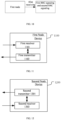
- the PUSCH in the present application is generated at the PHY301.
- the transmitting processor 416 and the multi-antenna transmitting processor 471 implement various signal processing functions for the L1 layer (i.e., the physical layer).
- the transmitting processor 416 implements coding and interleaving to facilitate forward error correction (FEC) at the second communication device 450 and mapping of signal clusters based on various modulation schemes (e.g., Binary Phase Shift Keying (BPSK), Quadrature Phase Shift Keying (QPSK), M-Phase Shift Keying (M-PSK), and M-Quadrature Amplitude Modulation (M-QAM)).
- FEC forward error correction
- BPSK Binary Phase Shift Keying
- QPSK Quadrature Phase Shift Keying
- M-PSK M-Phase Shift Keying
- M-QAM M-Quadrature Amplitude Modulation
- each receiver 454 receives a signal through its respective antenna 452.
- Each receiver 454 resumes information modulated onto a radio frequency carrier and converts the radio frequency flow into a baseband multi-carrier symbol flow to the receiving processor 456.
- the receiving processor 456 and the multi-antenna receiving processor 458 implement various signal processing functions of the L1 layer.
- the multi-antenna receiving processor 458 receives the simulated pre-coding/beam-forming operation for the baseband multi-carrier symbol flow from the receiver 454.
- the receiving processor 456 uses a Fast Fourier Transform (FFT) to transition the baseband multi-carrier symbol flow from the time domain to the frequency domain after receiving the simulated pre-coding/beam-forming operation.
- FFT Fast Fourier Transform
- the physical layer data signal and the reference signal are demultiplexed by the receiving processor 456, where the reference signal is used for channel estimation and the data signal recovers any spatial stream to the second communication device 450 for destination after multi-antenna detection by the multi-antenna receiving processor 458.
- the symbols on each spatial stream are demodulated and restored in the receiving processor 456 and generate a soft decision.
- the receiving processor 456 then decodes and de-interleaves the soft decision to resume the upper layer data and control signal transmitted by the first communications device 410 over the physical channel.
- the upper layer data and control signal are then provided to the controller/processor 459.
- the controller/processor 459 implements the functions of the L2 layer.
- the controller/processor 459 may be associated with the memory 460 that stores program code and data.
- the memory 460 may be referred to as a computer-readable medium.
- the controller/processor 459 provides multiplexing between the transmission and logical channel, packet reassembly, decryption, header decompression, control signal processing to recover the upper data packet from the core network.
- the upper layer data packet is then provided to all protocol layers above the L2 layer.
- Various control signals may also be provided to L3 for L3 processing.
- the data source 467 is used to provide the upper layer data packet to the controller/processor 459.
- the data source 467 represents all protocol layers above the L2 layer.
- the controller/processor 459 implements header compression, encryption, packet segmentation and reordering, and multiplexing between logic and transmission channels based on wireless resource allocation, implementing L2 layer functions for the user plane and control plane.
- the controller/processor 459 is also responsible for the retransmission of the lost package and the signaling to the first communication device 410.
- the transmitting processor 468 executes the modulation mapping, channel encoding, while the multi-antenna transmitting processor 457 performs digital multi-antenna spatial pre-coding, including both codebook-based pre-coding and non-codebook-based pre-coding, and beam-based processing, and then the transmitting processor 468 tailors the generated spatial stream to a multi-wave/single-wave symbol stream, which is provided to a different antenna 452 via the transmitter 454 after a simulated pre-encoded/beam operation in the multi-antenna transmitting processor 457.
- Each transmitter 454 first converts the baseband symbol flow provided by the multi-antenna transmitting processor 457 into a radio frequency symbol flow, which is then provided to the antenna 452.
- the function at the first communications device 410 is similar to the receiving function at the second communications device 450 described in the transmission from the first communications device 410 to the second communications device 450.
- Each receiver 418 receives a radio frequency signal through its respective antenna 420, converts the received radio frequency signal into a baseband signal, and provides the baseband signal to the multi-antenna receiving processor 472 and the receiving processor 470.
- the receiving processor 470 and the multi-antenna receiving processor 472 collectively implement the functions of the L1 layer.
- the controller/processor 475 implements the function of the L2 layer.
- the controller/processor 475 may be associated with the memory 476 storing program code and data.
- the memory 476 may be referred to as a computer-readable medium.
- the controller/processor 475 In the transmission from the second communication device 450 to the first communication device 410, the controller/processor 475 provides multiplexing between the transmission and logical channel, packet reassembly, decryption, header decompression, control signal processing to recover the upper data packet from the UE450.
- the upper layer data packet from the controller/processor 475 may be provided to the core network.
- the first node in the present application includes the second communications device 450 and the second node in the present application includes the first communications device 410.
- the first node is an user equipment and the second node is an user equipment.
- the first node is an user equipment and the second node is a relay node.
- the first node is a relay node and the second node is an user equipment.
- the first node is an user equipment and the second node is a base station device.
- the first node is a relay node and the second node is a base station device.
- the second node is an user equipment and the first node is a base station device.
- the second node is a relay node and the first node is a base station device.
- the first communications device 410 comprises: at least one controller/processor; at least one controller/processor is responsible for HARQ operation.
- the second communications device 450 includes: at least one processor, and at least one memory comprising computer program code; at least one memory and computer program code configured for use with at least one processor.
- the second communications device 450 device at least: receiving a plurality of RRC signaling; receiving a first DCI, and the first DCI is used to schedule PUSCH on a target cell set, and the target cell set comprising a plurality of cells; sending a PUSCH on each cell of the target cell set; wherein the first target domain set in the first DCI is applied to a plurality of cells in the target cell set; the first target domain set in the first DCI depends on the configuration of at least one RRC signaling in a plurality of RRC signaling, a plurality of RRC signaling are respectively configured for a plurality of cells in the target cell set, and the configurations of a plurality of RRC signaling are expected to be the same.
- the second communications device 450 corresponds to the first node in the present application.
- the second communications device 450 includes: a memory storing a computer-readable instruction program that, when executed by at least one processor, generates an action, the action comprising: receiving a plurality of RRC signaling; receiving a first DCI, and the first DCI is used to schedule PUSCH on a target cell set, and the target cell set comprising a plurality of cells; sending a PUSCH on each cell of the target cell set; wherein the first target domain set in the first DCI is applied to a plurality of cells in the target cell set; the first target domain set in the first DCI depends on the configuration of at least one RRC signaling in a plurality of RRC signaling, a plurality of RRC signaling are respectively configured for a plurality of cells in the target cell set, and the configurations of a plurality of RRC signaling are expected to be the same.
- the second communications device 450 corresponds to the first node in the present application.
- the first communications device 410 includes: at least one processor, and at least one memory comprising computer program code; at least one memory and computer program code configured for use with at least one processor.
- the first communications device 410 device at least: sending a plurality of RRC signaling; sending a first DCI, and the first DCI is used to schedule PUSCH on a target cell set, and the target cell set comprising a plurality of cells; receiving a PUSCH on each cell of the target cell set; wherein the first target domain set in the first DCI is applied to a plurality of cells in the target cell set; the first target domain set in the first DCI depends on the configuration of at least one RRC signaling in a plurality of RRC signaling, a plurality of RRC signaling are respectively configured for a plurality of cells in the target cell set, and the configurations of a plurality of RRC signaling are expected to be the same.
- the first communications device 410 includes: a memory storing a computer-readable instruction program that, when executed by at least one processor, generates an action, the action comprising: sending a plurality of RRC signaling; sending a first DCI, and the first DCI is used to schedule PUSCH on a target cell set, and the target cell set comprising a plurality of cells; receiving a PUSCH on each cell of the target cell set; wherein the first target domain set in the first DCI is applied to a plurality of cells in the target cell set; the first target domain set in the first DCI depends on the configuration of at least one RRC signaling in a plurality of RRC signaling, a plurality of RRC signaling are respectively configured for a plurality of cells in the target cell set, and the configurations of a plurality of RRC signaling are expected to be the same.
- the first communications device 410 corresponds to the second node in the present application.
- At least one of ⁇ the antenna 452, the receiver 454, the multi-antenna receiving processor 458, the receiving processor 456, the controller/processor 459, the memory 460, the data source 467 ⁇ is used to receive RRC signaling in the present application.
- At least one of ⁇ the antenna 420, the transmitter 418, the multi-antenna emitting processor 471, the emitting processor 416, the controller/processor 475, the memory 476 ⁇ is used to transmit one RRC signaling in the present application.
- At least one of ⁇ the antenna 452, the receiver 454, the multi-antenna receiving processor 458, the receiving processor 456, the controller/processor 459, the memory 460, the data source 467 ⁇ is used to receive the first DCI in the present application.
- At least one of ⁇ the antenna 420, the transmitter 418, the multi-antenna emitting processor 471, the emitting processor 416, the controller/processor 475, the memory 476 ⁇ is used to send the first DCI of the present application.
- At least one of ⁇ the antenna 452, the transmitter 454, the multi-antenna emitting processor 458, the emitting processor 468, the controller/processor 459, the memory 460, the data source 467 ⁇ is used to transmit PUSCH on each of the cell in the target cell set in the present application.
- At least one of ⁇ the antenna 420, the receiver 418, the multi-antenna receiving processor 472, the receiving processor 470, the controller/processor 475, the memory 476 ⁇ is used to receive PUSCH on each of the target cells in the target cell set in the present application.
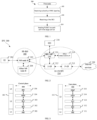
- Embodiment 5 exemplifies a flow diagram of wireless transmission according to one embodiment of the present application, as shown in FIG. 5 .
- the communication between the first node U1 and the second node U2 is via an air interface.
- the first node U1 receives a plurality of RRC signaling in step S511; receives a first DCI in step S512; and sends PUSCH on each cell in the target cell set in step S513.
- the second node, U2 sends a plurality of RRC signaling in step S521, a first DCI in step S522, and a PUSCH is received on each cell in the target cell set in step S523.
- the first DCI is used to schedule the PUSCH on the target cell set, and the target cell set comprising a plurality of cells; the first target domain set in the first DCI is applied to a plurality of cells in the target cell set; the first target domain set in the first DCI depends on the configuration of at least one RRC signaling in a plurality of RRC signaling, a plurality of RRC signaling are configured for a plurality of cells in the target cell set, respectively, and the configurations of a plurality of RRC signaling are expected to be the same; a plurality of RRC signaling belong to a plurality of PUSCH-Configs, respectively.
- the size of one domain in the first target domain set in the first DCI depends on the configuration of at least one RRC signaling in a plurality of RRC signaling.
- an indication of one domain in the first target domain set in the first DCI depends on the configuration of at least one RRC signaling of a plurality of RRC signaling.
- the first node U1 also receives first RRC signaling and second RRC signaling; the first node U2 also sends first RRC signaling and second RRC signaling; wherein the first DCI comprises a second target domain set, the second target domain set in the first DCI is applied to a plurality of cells in the target cell set; a plurality of cells in the target cell set comprises first cell and second cell, the first RRC signaling and the second RRC signaling is configured to the first cell and the second cell, respectively, and the configuration of the first RRC signaling is different from the configuration of the second RRC signaling; for the first cell, the indication of one domain of the second target domain set in the first DCI depends on the configuration of the first RRC signaling; for the second cell, the indication of the domain of the second target domain set in the first DCI depends on the configuration of the second RRC signaling.
- the first node U1 is the first node in the present application.
- the second node U2 is the second node in the present application.
- the first node U1 is a UE.
- the first node U1 is a base station.
- the second node U2 is a base station.
- the second node U2 is a UE.
- the air interface between the second node U2 and the first node U1 is a Uu interface.
- the air interface between the second node U2 and the first node U1 includes a cellular link.
- the air interface between the second node U2 and the first node U1 is a PC5 interface.
- the air interface between the second node U2 and the first node U1 includes a sidelink.
- the air interface between the second node U2 and the first node U1 includes a wireless interface between a base station device and an user equipment.
- the air interface between the second node U2 and the first node U1 includes a wireless interface between the satellite device and an user equipment.
- the air interface between the second node U2 and the first node U1 includes a wireless interface between an user equipment and the user equipment.
- issues to be addressed by the present application include: how to determine a relationship between the first target domain set in the first DCI and a plurality of RRC signaling.
- issues to be addressed by the present application include: how to determine a relationship between the first target domain set in the first DCI and a plurality of RRC signaling, as well as the relationship among a plurality of RRC signaling.
- issues to be addressed by the present application include: how to interpret the first target domain set in the first DCI.
- issues to be addressed by the present application include: how to determine the size of the domain in the first target domain set in the first DCI.
- issues to be addressed by the present application include: how to determine the configuration of relevant RRC signaling for DCI that schedule a plurality of cells.
- issues to be addressed by the present application include: how to reduce the signaling overhead of DCI.
- issues to be addressed by the present application include: how to improve the performance of eMBB.
- issues to be addressed by the present application include: how to improve the performance of MBS.
- issues to be addressed by the present application include: how to increase flexibility in base station scheduling or configuration.
- the first node determines its own processing of the first DCI.
- the first node processes the first DCI according to predefined rules if there are two different configurations of a plurality of RRC signaling.
- the processing of the first DCI by the first node depends on UE implementation if there are two different configurations of a plurality of RRC signaling.
- the first node processes the first target domain set in the first DCI according to predefined rules if the configuration of a plurality of RRC signaling is different from each other.
- the processing of the first node for the first target domain set in the first DCI depends on UE implementation if the configuration of a plurality of RRC signaling differs from one another.
- the first node believes that the existence of two different configurations of a plurality of RRC signaling is an error situation.
- the first node does not perform a decoding for the first DCI if there are two different configurations of a plurality of RRC signaling.
- Embodiment 7 exemplifies a schematic diagram of the relationship between a plurality of RRC signaling and a first target domain set in a first DCI according to one embodiment of the present application, as shown in FIG. 7 .
- the size of one domain of the first target domain set in the first DCI depends on the configuration of at least one RRC signaling in a plurality of RRC signaling.
- the size of one domain of the first target domain set in the first DCI is equal to a non-negative integer.
- the size of one domain of the first target domain set in the first DCI is equal to 0 or a positive integer.
- the first DCI does not include the domain in the first target domain set when the size of the domain in the first target domain set is equal to 0.
- the size of one domain of the first target domain set in the first DCI is equal to a positive integer.
- the size of a domain refers to the number of bits included in the domain.
- At least one RRC signaling of a plurality of RRC signaling is used to determine the size of one domain of the first target domain set in the first DCI.
- At least one RRC signaling of a plurality of RRC signaling is used to indicate the size of one domain of the first target domain set in the first DCI.
- At least one RRC signaling in a plurality of RRC signaling is used to configure the size of one domain of the first target domain set in the first DCI.
- Embodiment 8 exemplifies a schematic diagram of the relationship between a plurality of RRC signaling and a first target domain set in a first DCI according to one embodiment of the present application, as shown in FIG. 8 .
- the size of one domain of the first target domain set in the first DCI depends on the configuration of at least one RRC signaling in a plurality of RRC signaling.
- an indication of one domain of the first target domain set in the first DCI comprises: an indication of one domain of the first target domain set in the first DCI for a time domain resource.
- an indication of one domain of the first target domain set in the first DCI comprises: an indication of one domain of the first target domain set in the first DCI for a frequency domain resource.
- an indication of one domain of the first target domain set in the first DCI comprises: an indication of whether the domain of the first target domain set in the first DCI is a frequency hopping.
- an indication of one domain of the first target domain set in the first DCI comprises: an indication of the domain of the first target domain set in the first DCI for a MCS.
- an indication of one domain of the first target domain set in the first DCI comprises: an indication of the domain of the first target domain set in the first DCI for power control-related parameters of the PUSCH.
- an indication of one domain of the first target domain set in the first DCI comprises: an indication of the domain of the first target domain set in the first DCI for an SRS resource.
- an indication of one domain of the first target domain set in the first DCI comprises: an indication of the domain of the first target domain set in the first DCI for an SRS resource set.
- an indication of one domain of the first target domain set in the first DCI comprises: The domain of the first target domain set in the first DCI is for an indication of at least one of the pre-coding information or the number of transmission layers.
- an indication of one domain of the first target domain set in the first DCI comprises: an indication of the domain of the first target domain set in the first DCI for an Antenna ports.
- an indication of one domain of the first target domain set in the first DCI comprises: an indication of the domain of the first target domain set in the first DCI for information related to the CSI report.
- an indication of one domain of the first target domain set in the first DCI comprises: an indication that the domain of the first target domain set in the first DCI transmission information for CBG.
- an indication of one domain of the first target domain set in the first DCI comprises: an indication of the domain of the first target domain set in the first DCI for an association between PTRS and DMRS.
- an indication of one domain of the first target domain set in the first DCI comprises: an indication of the domain of the first target domain set in the first DCI for a beta_offset value.
- an indication of one domain of the first target domain set in the first DCI comprises: an indication of relevant information generated by the domain of the first target domain set in the first DCI for the DMRS sequence.
- an indication of one domain of the first target domain set in the first DCI comprises: an indication of the domain of the first target domain set in the first DCI for information that the SCell dormancy.
- an indication of one domain of the first target domain set in the first DCI comprises: an indication that the domain of the first target domain set in the first DCI sends a waveform for PUSCH.
- the indication of one domain of the first target domain set in the first DCI depends on the configuration of at least one RRC signaling of a plurality of RRC signaling.
- the indication of one domain of the first target domain set in the first DCI depends on the configuration of at least one RRC signaling of a plurality of RRC signaling.
- the indication of one domain of the first target domain sets in the first DCI is based on a table that depends on the configuration of at least one RRC signaling of a plurality of RRC signaling.
- one domain in the first target domain set in the first DCI indicates one of a value range for which at least one RRC signaling of a plurality of RRC signaling is used to configure this numerical range.
- the content indicated by one domain of the first target domain set in the first DCI is indicated by at least one RRC signaling of a plurality of RRC signaling.
- the meaning of bits in one domain of the first target domain sets in the first DCI depends on the configuration of at least one RRC signaling of a plurality of RRC signaling.
- the content indicated by the value of one domain of the first target domain sets in the first DCI depends on the configuration of at least one RRC signaling of a plurality of RRC signaling.
- a plurality of RRC signaling belongs to a plurality of PUSCH-ConfigCommons, and a plurality of PUSCH-ConfigCommons are configured for a plurality of cells in the target cell set, respectively.
- a plurality of RRC signaling belongs to a plurality of PUSCH-ServingCellConfigs, which are configured for a plurality of cells in the target cell set, respectively.
- the first DCI comprises a second target domain set, the second target domain set in the first DCI is applied to a plurality of cells in the target cell set; a plurality of cells in the target cell set comprises first cell and second cell, the first RRC signaling and the second RRC signaling is configured to the first cell and the second cell, respectively, and the configuration of the first RRC signaling is different from the configuration of the second RRC signaling; for the first cell, the indication of a domain of the second target domain set in the first DCI depends on the configuration of the first RRC signaling; for the second cell, the indication of the domain of the second target domain set in the first DCI depends on the configuration of the second RRC signaling.
- the first RRC signaling is received prior to the second RRC signaling.
- both the first RRC signaling and the second RRC signaling are received prior to the first DCI.
- the first RRC signaling is received after at least one RRC signaling of a plurality of RRC signaling.
- the first RRC signaling is received prior to at least one RRC signaling of a plurality of RRC signaling.
- At least one RRC signaling of the first RRC signaling and a plurality of RRC signaling is received simultaneously.
- the second RRC signaling is received after at least one RRC signaling of a plurality of RRC signaling.
- the second RRC signaling is received prior to at least one RRC signaling of a plurality of RRC signaling.
- At least one RRC signaling of the second RRC signaling and a plurality of RRC signaling is received simultaneously.
- a plurality of RRC signaling is received simultaneously.
- two RRC signaling in a plurality of RRC signaling that are received in sequence.
- the first RRC signaling does not belong to a plurality of RRC signaling.
- the second RRC signaling does not belong to a plurality of RRC signaling.
- only one of a first RRC signaling and a second RRC signaling belongs to a plurality of RRC signaling.
- the second target domain set is not intersected with the second target domain set.
- the second target domain set includes only one domain.
- the second target domain set includes a plurality of domains.
- one domain of the second target domain set includes at least one bit.
- one domain of the second target domain set includes non-negative integer bits.
- the second target domain set includes a Frequency domain resource assignment domain.
- the second target domain set includes a Modulation and coding scheme domain.
- the second target domain set includes a HARQ process number domain.
- the second target domain set includes a SRS resource indicator domain.
- the second target domain set includes a second SRS resource indicator domain.
- the second target domain set includes an Antenna ports domain.
- the second target domain set includes a CBG transmission information (CBGTI) domain.
- CBGTI CBG transmission information
- the second target domain set includes a Second PTRS-DMRS association domain.
- the second target domain set includes a UL-SCH indicator domain.
- the second target domain set includes a ChannelAccess-CPext-CAPC domain.
- the second target domain set includes an Open-loop power control parameter set indication domain.
- the second target domain set includes a SCell dormancy indication domain.
- the second target domain set includes a Priority indicator domain.
- the second target domain set includes a Minimum applicable scheduling offset indicator domain.
- the second target domain set includes a PDCCH monitoring adaptation indication domain.
- one domain in the second target domain set is used to indicate a frequency domain resource allocation.
- one domain in the second target domain set is used to indicate an association between PTRS and DMRS.
- one domain in the second target domain set is used to indicate a beta_offset value.
- the value of one domain in the second target domain sets is used for generation of the Demodulation reference signals (DMRS) sequence.
- DMRS Demodulation reference signals
- one domain in the second target domain set is used to indicate whether to enable Transform precoding.
- one domain in the second target domain set is used to trigger an aperiodic SRS resource set.
- one domain in the second target domain set is used to indicate an available slot offset.
- one domain in the second target domain set is used to indicate an open loop power control parameter set.
- one domain in the second target domain set is used to indicate a priority.
- one domain in the second target domain set is used to indicate an invalid symbol pattern.
- one domain in the second target domain set is used to indicate a minimum applicable scheduling offset.
- one domain in the second target domain set is used to indicate a skipping of PDCCH monitoring.
- the second target domain set in the first DCI is applied to the target cell set.
- the second target domain set in the first DCI is applied to each cell of the target cell set.
- the second target domain set in the first DCI is applied to the transmission of PUSCH on each cell of the target cell set.
- the second target domain set in the first DCI is applied to the transmission of a Reference signal(s) corresponding to PUSCH on each cell of the target cell set.
- the second target domain set in the first DCI is applied to a plurality of cells in the target cell set.
- the second target domain set in the first DCI is applied to each of a plurality of cells in the target cell set.
- the second target domain set in the first DCI is applied to the transmission of PUSCH on each of a plurality of cells in the target cell set.
- the second target domain set in the first DCI is applied to the transmission of a Reference signal(s) corresponding to PUSCH in each of a plurality of cells in the target cell set.
- the second target domain set expressing the first DCI is applied to a plurality of cells in the target cell set, comprising:
- the second target domain set in the first DCI includes scheduling information for PUSCH sent on all of a plurality of cells in the target cell set.
- the second target domain set expressing the first DCI is applied to a plurality of cells in the target cell set, comprising:
- the second target domain set in the first DCI includes an indication information for all of a plurality of cells in the target cell set.
- the second target domain set in the first DCI includes only part of the domain in the first DCI.
- an indication of one domain of the second target domain set in the first DCI comprises: an indication of the domain of the second target domain set in the first DCI for a time domain resource.
- an indication of one domain of the second target domain set in the first DCI comprises: an indication of whether the domain of the second target domain set in the first DCI is a frequency hopping.
- an indication of one domain of the second target domain set in the first DCI comprises: an indication of the domain of the second target domain set in the first DCI for a MCS.
- an indication of one domain of the second target domain set in the first DCI comprises: an indication of the domain of the second target domain set in the first DCI for a HARQ Process Number.
- an indication of one domain of the second target domain set in the first DCI comprises: an indication of the domain of the second target domain set in the first DCI for power control-related parameters of the PUSCH.
- an indication of one domain of the second target domain set in the first DCI comprises: an indication of the domain of the second target domain set in the first DCI for an SRS resource.
- an indication of one domain of the second target domain set in the first DCI comprises: an indication of the domain of the second target domain set in the first DCI for an SRS resource set.
- an indication of one domain of the second target domain set in the first DCI comprises: an indication of the domain of the second target domain set in the first DCI for at least one of the pre-coding information or the number of transmission layers.
- an indication of one domain of the second target domain set in the first DCI comprises: an indication of the domain of the second target domain set in the first DCI for an Antenna ports.
- an indication of one domain of the second target domain set in the first DCI comprises: an indication of the domain of the second target domain set in the first DCI for information related to the CSI report.
- an indication of one domain of the second target domain set in the first DCI comprises: an indication that the domain of the second target domain set in the first DCI transmits information for the CBG.
- an indication of one domain of the second target domain set in the first DCI comprises: the indication of the domain of the second target domain set in the first DCI for an association between PTRS and DMRS.
- an indication of one domain of the second target domain set in the first DCI comprises: an indication of the domain of the second target domain set in the first DCI for a beta_offset value.
- an indication of one domain of the second target domain set in the first DCI comprises: an indication of relevant information generated by the domain of the second target domain set in the first DCI for the DMRS sequence.
- an indication of one domain of the second target domain set in the first DCI comprises: an indication of the domain of the second target domain set in the first DCI for information of the SCell dormancy.
- an indication of one domain of the second target domain set in the first DCI comprises: an indication that the domain of the second target domain set in the first DCI sends a waveform for PUSCH.
- an indication of one domain of the second target domain set in the first DCI comprises: an indication of the domain of the second target domain set in the first DCI of whether to enable Transform precoding.
- the indication of one domain of the second target domain set in the first DCI that one of the domains depends on the configuration of RRC signaling includes: The indication of the domain of the second target domain set in the first DCI depends on the configuration of this RRC signaling.
- the indication of one domain of the second target domain set in the first DCI that one of the domains depends on the configuration of RRC signaling includes: the indication of the domain of the second target domain set in the first DCI depends on the configuration of this RRC signaling.
- the indication of one domain of the second target domain set in the first DCI that one of the domains depends on the configuration of RRC signaling includes: the indication of the domain of the second target domain set in the first DCI is based on a table (table) that depends on the configuration of this RRC signaling.
- the indication of one domain of the second target domain set in the first DCI that one of the domains depends on the configuration of RRC signaling includes: the domain of the second target domain set in the first DCI indicates a value in a range of values that RRC signaling is used to configure.
- the indication of one domain of the second target domain set in the first DCI that one of the domains depends on the configuration of RRC signaling includes: the content indicated by the domain of the second target domain set in the first DCI is indicated by this RRC signaling.
- the indication of one domain of the second target domain set in the first DCI that one of the domains depends on the configuration of RRC signaling includes: The meaning of bits in the domain of the second target domain set in the first DCI depends on the configuration of the RRC signaling.
- the indication of one domain of the second target domain set in the first DCI that one of the domains depends on the configuration of RRC signaling includes: the content indicated by the value of the domain of the second target domain set in the first DCI depends on the configuration of the RRC signaling.
- the indication of one domain of the second target domain set in the first DCI that one of the domains depends on the configuration of RRC signaling includes: this RRC signaling is used to configure what is indicated by the value of the domain of the second target domain set in the first DCI.
- the indication of one domain of the second target domain set in the first DCI that one of the domains depends on the configuration of RRC signaling includes: this RRC signaling is used to configure an indication of the domain of the second target domain set in the first DCI.
- the first cell is different from the second cell.
- the first RRC signaling is used to determine the Number of repetitions for data.
- the first RRC signaling is used to determine a Transmission scheme for PUSCH.
- the transmission scheme is one of the transmission of codebook-based, non-codebook-based, and single antenna ports.
- the transmission scheme is one of codebook-based transmission and non-codebook-based transmission.
- the first RRC signaling is used to determine a DMRS configuration for PUSCH transmission using PUSCH mapping type A.
- the first RRC signaling is used to determine a DMRS configuration for PUSCH transmission using PUSCH mapping type B.
- the first RRC signaling is used to determine the power control of PUSCH.
- the first RRC signaling is used to determine a frequency displacement offsets(s) set.
- the first RRC signaling is used to determine the frequency domain resource distribution type.
- the first RRC signaling is used to determine a List of time domain allocations for timing of UL assignment to UL data.
- the first RRC signaling is used to determine whether the transform pre-coding is enabled or not.
- the first RRC signaling is used to determine a particular selection of a transformer precoder for PUSCH.
- the transmission scheme is one of the transmission of codebook-based, non-codebook-based, and single antenna ports.
- the transmission scheme is one of codebook-based transmission and non-codebook-based transmission.
- the first RRC signaling is used to indicate a DMRS configuration transmitted using PUSCH mapping type A.
- the first RRC signaling is used to indicate a frequency hopping mode.
- the first RRC signaling is used to indicate a transmission scheme of PUSCH, the first target domain set comprising pre-coding information and a layer number domain.
- the first RRC signaling is a txConfig, the first target domain set including pre-coding information and layer number domains.
- the name of the first RRC signaling includes a transformPrecoder
- the first target domain set includes PTRS-DMRS associated domains.
- the first RRC signaling is used to indicate whether the transform pre-coding is enabled, and the first target domain set includes PTRS-DMRS associated domains.
- the first RRC signaling is a transformPrecoder, the first target domain set comprising a DMRS sequence initialization domain.
- the first RRC signaling is used to determine a List of time domain allocations for timing of UL assignment to UL data.
- the first RRC signaling is used to indicate a particular selection of a transformer precoder for PUSCH.
- the first RRC signaling is used to indicate the Subset of PMIs addressed by TPMI.
- the first RRC signaling is used to indicate information of a DMRS bundling for PUSCH.
- the first RRC signaling is used to indicate: When two SRS resource sets are configured for PUSCH transmission and PUSCH transmission occasions are associated with two SRS resource sets, whether the Cyclical mapping pattern or Sequential mapping pattern should be followed.
- the first RRC signaling is used to determine the presence of an Antenna ports domain.
- the first RRC signaling is used to indicate the presence or absence of a DMRS Sequence Initialization domain.
- the first RRC signaling is used to determine the size of the HARQ process number domain.
- the first RRC signaling is used to determine a list of minimum K2 values.
- the first RRC signaling is used to determine the size of the Redundancy version domain.
- the first RRC signaling is used to determine the number of symbols that are invalid for PUSCH repetition type B after the last semi-static Downlink (DL) symbol.
- the first RRC signaling is used to determine the presence or absence of a priority indicator domain.
- the first RRC signaling is used to determine whether PUSCH repetition type A is followed or PUSCH repetition type B is followed.
- the first RRC signaling is used to determine the RV offset configured for the starting Redundancy version (RV) for a first repetition (the first actual repetition in PUSCH repetition type B) corresponding to a second SRS resource set for PUSCH.
- RV Redundancy version
- the first RRC signaling is used to determine a combined list of cycle prefix extensions, channel access priority classes (CAPC) and Uplink (UL) channel access types.
- CAC channel access priority classes
- UL Uplink
- the first RRC signaling is used to determine the UL full power transmission mode.
- the first RRC signaling is used to determine the scheduling granularity applicable to the origin and length indications of the resource allocation type 1.
- the first RRC signaling includes a txConfig.
- the first RRC signaling includes an uci-OnPUSCH.
- the first RRC signaling is a txConfig.
- the first RRC signaling is a frequencyHopping.
- the first RRC signaling is a mcs-Table.
- the first RRC signaling is an uci-OnPUSCH.
- the first RRC signaling is a tp-pi2BPSK.
- the name of the first RRC signaling includes a txConfig.
- the name of the first RRC signaling includes a resourceAllocation.
- the name of the first RRC signaling includes a codebookSubset.
- the name of the first RRC signaling includes a rbg-size.
- the name of the first RRC signaling includes a dmrs-SequenceInitialization.
- the name of the first RRC signaling includes a numberOfBitsForRV.
- the name of the first RRC signaling includes an antennaPortsFieldPresence.
- the name of the first RRC signaling includes a priorityIndicator.
- the name of the first RRC signaling includes a push-RepTypeIndicator.
- the name of the first RRC signaling includes an ul-FullPowerTransmission.
- the name of the first RRC signaling includes a numberOfInvalidSymbolsForDL-UL-Switching.
- the name of the first RRC signaling includes a -r16.
- the first RRC signaling is used to determine (in addition to msg3) a P0 value for PUSCH grant.
- the first RRC signaling is used to indicate the number of maximum CBGs per TB.
- the first RRC signaling is used to indicate whether CBG-based transmission is enabled.
- the first RRC signaling is used to determine the maximum Multiple-Input Multiple-Output (MIMO) layer for PUSCH in all Bandwidth parts (BWPs) of the UL corresponding to the cell.
- MIMO Multiple-Input Multiple-Output
- the first RRC signaling is used to indicate whether to enable the configuration of the advanced processing time capability 2 for PUSCH.
- the first RRC signaling is used to indicate a HARQ mode for a HARQ process ID.
- the first RRC signaling is used to indicate the power offset between msg3 and Random Access Channel(s) (RACH) preamble transmission.
- the first RRC signaling is used to indicate (in addition to msg3) a P0 value for PUSCH grant.
- the first RRC signaling is a codeBlockGroupTransmission.
- the first RRC signaling is a rateMatching.
- the first RRC signaling is a xOverhead.
- the first RRC signaling is a processingType2Enabled.
- the first RRC signaling is a nrofHARQ-ProcessesForPUSCH-r17.
- the first RRC signaling is a groupHopingEnabledTransformPrecoding.
- the first RRC signaling is a msg3-DeltaPreamble.
- the first RRC signaling is a p0-NominalWithGrant.
- the name of the first RRC signaling includes a codeBlockGroupTransmission.
- the name of the first RRC signaling includes a rateMatching.
- the name of the first RRC signaling includes a xOverhead.
- the name of the first RRC signaling includes a maxMIMO-Layers.
- the name of the first RRC signaling includes a processingType2Enabled.
- the name of the first RRC signaling includes a nrofHARQ-ProcessesForPUSCH.
- the name of the first RRC signaling includes an uplinkHARQ-mode.
- the name of the first RRC signaling includes a groupHoppingEnabledTransformPrecoding.
- the name of the first RRC signaling includes a msg3-DeltaPreamble.
- the name of the first RRC signaling includes a p0-NominalWithGrant.
- the first RRC signaling includes at least a portion of SRS-Config.
- the first RRC signaling is a SRS-Config.
- the name of the first RRC signaling includes a SRS-Config.
- the first RRC signaling includes an AvailableSlotOffset.
- the transmission scheme is one of the transmission of codebook-based, non-codebook-based, and single antenna ports.
- the transmission scheme is one of codebook-based transmission and non-codebook-based transmission.
- the second RRC signaling is used to determine a DMRS configuration for PUSCH transmission using PUSCH mapping type A.
- the second RRC signaling is used to determine a DMRS configuration for PUSCH transmission using PUSCH mapping type B.
- the second RRC signaling is used to determine the power control of PUSCH.
- the second RRC signaling is used to determine the frequency hopping mode.
- the second RRC signaling is used to determine a frequency hopping offset(s) set.
- the second RRC signaling is used to determine a particular selection of a transformer precoder for PUSCH.
- the second RRC signaling is used to determine the RBG size for PUSCH selected between Configuration 1 and Configuration 2.
- the second RRC signaling is used to determine a combined list of cycle prefix extensions, channel access priority classes (CAPC) and Uplink (UL) channel access types.
- CAC channel access priority classes
- UL Uplink
- the second RRC signaling includes a txConfig.
- the second RRC signaling includes a push-PowerControl.
- the second RRC signaling includes a resourceAllocation.
- the second RRC signaling includes a push-TimeDomainAllocationList.
- the second RRC signaling includes a transformPrecoder.
- the second RRC signaling includes a codebookSubset.
- the second RRC signaling includes a maxRank.
- the second RRC signaling includes a rbg-size.
- the second RRC signaling includes an uci-OnPUSCH.
- the second RRC signaling includes a tp-pi2BPSK.
- the second RRC signaling is a push-AggregationFactor.
- the second RRC signaling is a txConfig.
- the second RRC signaling is a push-PowerControl.
- the second RRC signaling is a frequencyHopping.
- the second RRC signaling is a frequencyHoppingOffsetLists.
- the second RRC signaling is a resourceAllocation.
- the second RRC signaling is a push-TimeDomainAllocationList.
- the second RRC signaling is a mcs-Table.
- the second RRC signaling is a mcs-TableTransformPrecoder.
- the second RRC signaling is a transformPrecoder.
- the second RRC signaling is a codebookSubset.
- the second RRC signaling is a maxRank.
- the second RRC signaling is a rbg-size.
- the second RRC signaling is an uci-OnPUSCH.
- the second RRC signaling is a tp-pi2BPSK.
- the name of the second RRC signaling includes a push-AgggregationFactor.
- the name of the second RRC signaling includes a txConfig.
- the name of the second RRC signaling includes a dmrs-UplinkForPUSCH-MappingTypeA.
- the name of the second RRC signaling includes a dmrs-UplinkForPUSCH-MappingTypeB.
- the name of the second RRC signaling includes a push-PowerControl.
- the name of the second RRC signaling includes a frequencyHopping.
Landscapes
- Engineering & Computer Science (AREA)
- Computer Networks & Wireless Communication (AREA)
- Signal Processing (AREA)
- Mobile Radio Communication Systems (AREA)
Applications Claiming Priority (2)
| Application Number | Priority Date | Filing Date | Title |
|---|---|---|---|
| CN202210946354.XA CN117768073A (zh) | 2022-08-08 | 2022-08-08 | 一种被用于无线通信的节点中的方法和装置 |
| PCT/CN2023/111145 WO2024032481A1 (zh) | 2022-08-08 | 2023-08-04 | 一种被用于无线通信的节点中的方法和装置 |
Publications (1)
| Publication Number | Publication Date |
|---|---|
| EP4580286A1 true EP4580286A1 (de) | 2025-07-02 |
Family
ID=89850768
Family Applications (1)
| Application Number | Title | Priority Date | Filing Date |
|---|---|---|---|
| EP23851702.3A Pending EP4580286A1 (de) | 2022-08-08 | 2023-08-04 | Verfahren und vorrichtung für knoten zur verwendung in der drahtlosen kommunikation |
Country Status (3)
| Country | Link |
|---|---|
| EP (1) | EP4580286A1 (de) |
| CN (1) | CN117768073A (de) |
| WO (1) | WO2024032481A1 (de) |
Family Cites Families (4)
| Publication number | Priority date | Publication date | Assignee | Title |
|---|---|---|---|---|
| CN111245586B (zh) * | 2020-01-10 | 2022-03-25 | 北京紫光展锐通信技术有限公司 | Dci的生成方法、小区的调度方法、系统、设备和介质 |
| CN111543104B (zh) * | 2020-02-10 | 2023-10-03 | 北京小米移动软件有限公司 | Dci的传输方法、装置、通信设备及存储介质 |
| US11564247B2 (en) * | 2020-02-13 | 2023-01-24 | Qualcomm Incorporated | Time domain resource assignment for multiple cells scheduled by a single downlink control information message |
| US11632787B2 (en) * | 2020-02-13 | 2023-04-18 | Qualcomm Incorporated | Bandwidth part indication for multiple cells scheduled by a single downlink control information message |
-
2022
- 2022-08-08 CN CN202210946354.XA patent/CN117768073A/zh active Pending
-
2023
- 2023-08-04 EP EP23851702.3A patent/EP4580286A1/de active Pending
- 2023-08-04 WO PCT/CN2023/111145 patent/WO2024032481A1/zh not_active Ceased
Also Published As
| Publication number | Publication date |
|---|---|
| CN117768073A (zh) | 2024-03-26 |
| WO2024032481A1 (zh) | 2024-02-15 |
Similar Documents
| Publication | Publication Date | Title |
|---|---|---|
| US11817979B2 (en) | Method and device in nodes used for wireless communication | |
| US12537653B2 (en) | Method and apparatus for resource management of overlapping transmissions | |
| US20220376881A1 (en) | Method and device in nodes used for wireless communication | |
| CN111615193B (zh) | 一种被用于无线通信的用户设备、基站中的方法和装置 | |
| CN113630892A (zh) | 一种被用于无线通信的节点中的方法和装置 | |
| CN112839384B (zh) | 一种被用于无线通信的节点中的方法和装置 | |
| CN113709889A (zh) | 一种被用于无线通信的用户设备、基站中的方法和装置 | |
| EP4311330A1 (de) | Verfahren und vorrichtung zur verwendung in einem knoten für drahtlose kommunikation | |
| EP4580099A1 (de) | Verfahren und vorrichtung zur verwendung in einem knoten für drahtlose kommunikation | |
| CN114916073A (zh) | 一种被用于无线通信的节点中的方法和装置 | |
| CN116056142A (zh) | 一种被用于无线通信的节点中的方法和装置 | |
| CN115085878A (zh) | 一种被用于无线通信的节点中的方法和装置 | |
| EP4580103A1 (de) | Verfahren und vorrichtung zur verwendung in einem drahtloskommunikationsknoten | |
| US20260089741A1 (en) | Method and apparatus for multi-carrier scheduling in wireless communication | |
| EP4580286A1 (de) | Verfahren und vorrichtung für knoten zur verwendung in der drahtlosen kommunikation | |
| EP4580102A1 (de) | Verfahren und vorrichtung zur verwendung in einem knoten für drahtlose kommunikation | |
| EP4580292A1 (de) | Verfahren und vorrichtung zur verwendung in einem knoten für drahtlose kommunikation | |
| US12250686B2 (en) | Method and device in nodes used for wireless communication | |
| EP4580289A1 (de) | Verfahren und vorrichtung zur verwendung in einem drahtloskommunikationsknoten | |
| EP4601354A1 (de) | Verfahren und vorrichtung zur verwendung in einem knoten für drahtlose kommunikation | |
| EP4668947A1 (de) | Verfahren und vorrichtung zur verwendung in einem knoten für drahtlose kommunikation | |
| EP4618461A1 (de) | Verfahren und vorrichtung zur drahtlosen kommunikation | |
| CN113411887B (zh) | 一种被用于无线通信的节点中的方法和装置 | |
| WO2025103252A1 (zh) | 一种用于无线通信的节点中的方法和装置 | |
| EP4723774A1 (de) | Verfahren und vorrichtung zur verwendung in einem knoten für drahtlose kommunikation |
Legal Events
| Date | Code | Title | Description |
|---|---|---|---|
| STAA | Information on the status of an ep patent application or granted ep patent |
Free format text: STATUS: THE INTERNATIONAL PUBLICATION HAS BEEN MADE |
|
| PUAI | Public reference made under article 153(3) epc to a published international application that has entered the european phase |
Free format text: ORIGINAL CODE: 0009012 |
|
| STAA | Information on the status of an ep patent application or granted ep patent |
Free format text: STATUS: REQUEST FOR EXAMINATION WAS MADE |
|
| 17P | Request for examination filed |
Effective date: 20250526 |
|
| AK | Designated contracting states |
Kind code of ref document: A1 Designated state(s): AL AT BE BG CH CY CZ DE DK EE ES FI FR GB GR HR HU IE IS IT LI LT LU LV MC ME MK MT NL NO PL PT RO RS SE SI SK SM TR |
|
| RAP1 | Party data changed (applicant data changed or rights of an application transferred) |
Owner name: APOGEE NETWORKS, LLC |
|
| DAV | Request for validation of the european patent (deleted) | ||
| DAX | Request for extension of the european patent (deleted) |