EP4580280A1 - Verfahren und vorrichtung zur übertragung von nr-sidelink unter berücksichtigung der bandbreitenanforderung eines besetzten kanals in einem unlizenzierten band - Google Patents
Verfahren und vorrichtung zur übertragung von nr-sidelink unter berücksichtigung der bandbreitenanforderung eines besetzten kanals in einem unlizenzierten band Download PDFInfo
- Publication number
- EP4580280A1 EP4580280A1 EP23857731.6A EP23857731A EP4580280A1 EP 4580280 A1 EP4580280 A1 EP 4580280A1 EP 23857731 A EP23857731 A EP 23857731A EP 4580280 A1 EP4580280 A1 EP 4580280A1
- Authority
- EP
- European Patent Office
- Prior art keywords
- prb
- dedicated
- resource
- psfch
- channel
- Prior art date
- Legal status (The legal status is an assumption and is not a legal conclusion. Google has not performed a legal analysis and makes no representation as to the accuracy of the status listed.)
- Pending
Links
Images


Classifications
-
- H—ELECTRICITY
- H04—ELECTRIC COMMUNICATION TECHNIQUE
- H04L—TRANSMISSION OF DIGITAL INFORMATION, e.g. TELEGRAPHIC COMMUNICATION
- H04L27/00—Modulated-carrier systems
- H04L27/26—Systems using multi-frequency codes
- H04L27/2601—Multicarrier modulation systems
-
- H—ELECTRICITY
- H04—ELECTRIC COMMUNICATION TECHNIQUE
- H04W—WIRELESS COMMUNICATION NETWORKS
- H04W72/00—Local resource management
- H04W72/20—Control channels or signalling for resource management
- H04W72/25—Control channels or signalling for resource management between terminals via a wireless link, e.g. sidelink
-
- H—ELECTRICITY
- H04—ELECTRIC COMMUNICATION TECHNIQUE
- H04L—TRANSMISSION OF DIGITAL INFORMATION, e.g. TELEGRAPHIC COMMUNICATION
- H04L1/00—Arrangements for detecting or preventing errors in the information received
- H04L1/12—Arrangements for detecting or preventing errors in the information received by using return channel
- H04L1/16—Arrangements for detecting or preventing errors in the information received by using return channel in which the return channel carries supervisory signals, e.g. repetition request signals
- H04L1/18—Automatic repetition systems, e.g. Van Duuren systems
- H04L1/1812—Hybrid protocols; Hybrid automatic repeat request [HARQ]
-
- H—ELECTRICITY
- H04—ELECTRIC COMMUNICATION TECHNIQUE
- H04L—TRANSMISSION OF DIGITAL INFORMATION, e.g. TELEGRAPHIC COMMUNICATION
- H04L1/00—Arrangements for detecting or preventing errors in the information received
- H04L1/12—Arrangements for detecting or preventing errors in the information received by using return channel
- H04L1/16—Arrangements for detecting or preventing errors in the information received by using return channel in which the return channel carries supervisory signals, e.g. repetition request signals
- H04L1/18—Automatic repetition systems, e.g. Van Duuren systems
- H04L1/1829—Arrangements specially adapted for the receiver end
- H04L1/1854—Scheduling and prioritising arrangements
-
- H—ELECTRICITY
- H04—ELECTRIC COMMUNICATION TECHNIQUE
- H04L—TRANSMISSION OF DIGITAL INFORMATION, e.g. TELEGRAPHIC COMMUNICATION
- H04L1/00—Arrangements for detecting or preventing errors in the information received
- H04L1/12—Arrangements for detecting or preventing errors in the information received by using return channel
- H04L1/16—Arrangements for detecting or preventing errors in the information received by using return channel in which the return channel carries supervisory signals, e.g. repetition request signals
- H04L1/18—Automatic repetition systems, e.g. Van Duuren systems
- H04L1/1829—Arrangements specially adapted for the receiver end
- H04L1/1861—Physical mapping arrangements
-
- H—ELECTRICITY
- H04—ELECTRIC COMMUNICATION TECHNIQUE
- H04L—TRANSMISSION OF DIGITAL INFORMATION, e.g. TELEGRAPHIC COMMUNICATION
- H04L5/00—Arrangements affording multiple use of the transmission path
-
- H—ELECTRICITY
- H04—ELECTRIC COMMUNICATION TECHNIQUE
- H04L—TRANSMISSION OF DIGITAL INFORMATION, e.g. TELEGRAPHIC COMMUNICATION
- H04L5/00—Arrangements affording multiple use of the transmission path
- H04L5/003—Arrangements for allocating sub-channels of the transmission path
- H04L5/0053—Allocation of signalling, i.e. of overhead other than pilot signals
- H04L5/0055—Physical resource allocation for ACK/NACK
-
- H—ELECTRICITY
- H04—ELECTRIC COMMUNICATION TECHNIQUE
- H04W—WIRELESS COMMUNICATION NETWORKS
- H04W16/00—Network planning, e.g. coverage or traffic planning tools; Network deployment, e.g. resource partitioning or cells structures
- H04W16/14—Spectrum sharing arrangements between different networks
-
- H—ELECTRICITY
- H04—ELECTRIC COMMUNICATION TECHNIQUE
- H04W—WIRELESS COMMUNICATION NETWORKS
- H04W72/00—Local resource management
- H04W72/04—Wireless resource allocation
- H04W72/044—Wireless resource allocation based on the type of the allocated resource
- H04W72/0446—Resources in time domain, e.g. slots or frames
-
- H—ELECTRICITY
- H04—ELECTRIC COMMUNICATION TECHNIQUE
- H04W—WIRELESS COMMUNICATION NETWORKS
- H04W72/00—Local resource management
- H04W72/04—Wireless resource allocation
- H04W72/044—Wireless resource allocation based on the type of the allocated resource
- H04W72/0453—Resources in frequency domain, e.g. a carrier in FDMA
-
- H—ELECTRICITY
- H04—ELECTRIC COMMUNICATION TECHNIQUE
- H04W—WIRELESS COMMUNICATION NETWORKS
- H04W72/00—Local resource management
- H04W72/12—Wireless traffic scheduling
- H04W72/1263—Mapping of traffic onto schedule, e.g. scheduled allocation or multiplexing of flows
-
- H—ELECTRICITY
- H04—ELECTRIC COMMUNICATION TECHNIQUE
- H04W—WIRELESS COMMUNICATION NETWORKS
- H04W52/00—Power management, e.g. Transmission Power Control [TPC] or power classes
- H04W52/04—Transmission power control [TPC]
- H04W52/30—Transmission power control [TPC] using constraints in the total amount of available transmission power
- H04W52/36—Transmission power control [TPC] using constraints in the total amount of available transmission power with a discrete range or set of values, e.g. step size, ramping or offsets
- H04W52/367—Power values between minimum and maximum limits, e.g. dynamic range
-
- H—ELECTRICITY
- H04—ELECTRIC COMMUNICATION TECHNIQUE
- H04W—WIRELESS COMMUNICATION NETWORKS
- H04W52/00—Power management, e.g. Transmission Power Control [TPC] or power classes
- H04W52/04—Transmission power control [TPC]
- H04W52/38—TPC being performed in particular situations
- H04W52/383—TPC being performed in particular situations power control in peer-to-peer links
-
- H—ELECTRICITY
- H04—ELECTRIC COMMUNICATION TECHNIQUE
- H04W—WIRELESS COMMUNICATION NETWORKS
- H04W92/00—Interfaces specially adapted for wireless communication networks
- H04W92/16—Interfaces between hierarchically similar devices
- H04W92/18—Interfaces between hierarchically similar devices between terminal devices
Definitions
- This disclosure relates to a wireless communication system.
- SL communication is a communication scheme in which a direct link is established between User Equipments (UEs) and the UEs exchange voice and data directly with each other without intervention of an evolved Node B (eNB).
- UEs User Equipments
- eNB evolved Node B
- SL communication is under consideration as a solution to the overhead of an eNB caused by rapidly increasing data traffic.
- V2X Vehicle-to-everything refers to a communication technology through which a vehicle exchanges information with another vehicle, a pedestrian, an entity having an infrastructure (or infra) established therein, and so on.
- the V2X may be spread into 4 types, such as vehicle-to-vehicle (V2V), vehicle-to-infrastructure (V2I), vehicle-to-network (V2N), and vehicle-to-pedestrian (V2P).
- V2V vehicle-to-vehicle
- V2I vehicle-to-infrastructure
- V2N vehicle-to-network
- V2P vehicle-to-pedestrian
- the V2X communication may be provided via a PC5 interface and/or Uu interface.
- RAT Radio Access Technology
- NR new radio access technology
- a method for performing, by a first device, wireless communication may be proposed.
- the method may comprise: obtaining information related to a resource block, RB, set, wherein the RB set may include a physical sidelink feedback channel, PSFCH, resource, and wherein the PFSCH resource may include at least one dedicated physical resource block, PRB, and at least one common PRB, included within a bandwidth of 1 MHz; and based on the at least one dedicated PRB and the at least one common PRB being included within the bandwidth of 1 MHz, transmitting hybrid automatic repeat request, HARQ, feedback information, based on the at least one dedicated PRB.
- HARQ hybrid automatic repeat request
- a first device for performing wireless communication may comprise: at least one transceiver; at least one processor; and at least one memory operably connected to the at least one processor and storing instructions that, based on being executed by the at least one processor, cause the first device to perform operations.
- the operations may comprise: obtaining information related to a resource block, RB, set, wherein the RB set may include a physical sidelink feedback channel, PSFCH, resource, and wherein the PFSCH resource may include at least one dedicated physical resource block, PRB, and at least one common PRB, included within a bandwidth of 1 MHz; and based on the at least one dedicated PRB and the at least one common PRB being included within the bandwidth of 1 MHz, transmitting hybrid automatic repeat request, HARQ, feedback information, based on the at least one dedicated PRB.
- the RB set may include a physical sidelink feedback channel, PSFCH, resource
- the PFSCH resource may include at least one dedicated physical resource block, PRB, and at least one common PRB, included within a bandwidth of 1 MHz; and based on the at least one dedicated PRB and the at least one common PRB being included within the bandwidth of 1 MHz, transmitting hybrid automatic repeat request, HARQ, feedback information, based on the at least one dedicated PRB.
- a device adapted to control a first user equipment, UE may be proposed.
- the device may comprise: at least one processor; and at least one memory operably connected to the at least one processor and storing instructions that, based on being executed by the at least one processor, cause the first UE to perform operations.
- the operations may comprise: obtaining information related to a resource block, RB, set, wherein the RB set may include a physical sidelink feedback channel, PSFCH, resource, and wherein the PFSCH resource may include at least one dedicated physical resource block, PRB, and at least one common PRB, included within a bandwidth of 1 MHz; and based on the at least one dedicated PRB and the at least one common PRB being included within the bandwidth of 1 MHz, transmitting hybrid automatic repeat request, HARQ, feedback information, based on the at least one dedicated PRB.
- the RB set may include a physical sidelink feedback channel, PSFCH, resource
- the PFSCH resource may include at least one dedicated physical resource block, PRB, and at least one common PRB, included within a bandwidth of 1 MHz; and based on the at least one dedicated PRB and the at least one common PRB being included within the bandwidth of 1 MHz, transmitting hybrid automatic repeat request, HARQ, feedback information, based on the at least one dedicated PRB.
- a non-transitory computer-readable storage medium storing instructions may be proposed.
- the instructions based on being executed, may cause a first device to: obtain information related to a resource block, RB, set, wherein the RB set may include a physical sidelink feedback channel, PSFCH, resource, and wherein the PFSCH resource may include at least one dedicated physical resource block, PRB, and at least one common PRB, included within a bandwidth of 1 MHz; and based on the at least one dedicated PRB and the at least one common PRB being included within the bandwidth of 1 MHz, transmit hybrid automatic repeat request, HARQ, feedback information, based on the at least one dedicated PRB.
- HARQ hybrid automatic repeat request
- a method for performing, by a second device, wireless communication may be proposed.
- the method may comprise: receiving, from a first device, hybrid automatic repeat request, HARQ, feedback information based on at least one dedicated physical resource block, PRB, wherein the HARQ feedback information may be transmitted based on the at least one PRB from the first device based on the at least one dedicated PRB and at least one common PRB being included within a bandwidth of 1 MHz, and wherein the at least one dedicated PRB and the at least one common PRB may be included in a physical sidelink feedback channel, PSFCH, resource.
- PSFCH physical sidelink feedback channel
- the BWP may be at least any one of an active BWP, an initial BWP, and/or a default BWP.
- the UE may not monitor downlink radio link quality in a DL BWP other than an active DL BWP on a primary cell (PCell).
- the UE may not receive PDCCH, physical downlink shared channel (PDSCH), or channel state information - reference signal (CSI-RS) (excluding RRM) outside the active DL BWP.
- the UE may not trigger a channel state information (CSI) report for the inactive DL BWP.
- the UE may not transmit physical uplink control channel (PUCCH) or physical uplink shared channel (PUSCH) outside an active UL BWP.
- PUCCH physical uplink control channel
- PUSCH physical uplink shared channel
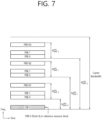
- FIG. 7 shows an example of a BWP, based on an embodiment of the present disclosure.
- the embodiment of FIG. 7 may be combined with various embodiments of the present disclosure. It is assumed in the embodiment of FIG. 7 that the number of BWPs is 3.
- V2X or SL communication will be described.
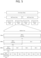
- a physical sidelink broadcast channel may be a (broadcast) channel for transmitting default (system) information which must be first known by the UE before SL signal transmission/reception.
- the default information may be information related to SLSS, a duplex mode (DM), a time division duplex (TDD) uplink/downlink (UL/DL) configuration, information related to a resource pool, a type of an application related to the SLSS, a subframe offset, broadcast information, or the like.
- DM duplex mode
- TDD time division duplex
- UL/DL uplink/downlink
- a payload size of the PSBCH may be 56 bits including 24-bit cyclic redundancy check (CRC).
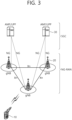
- FIG. 8 shows a procedure of performing V2X or SL communication by a UE based on a transmission mode, based on an embodiment of the present disclosure.
- the transmission mode may be called a mode or a resource allocation mode.
- the transmission mode may be called an LTE transmission mode.
- the transmission mode may be called an NR resource allocation mode.
- (a) of FIG. 8 shows a UE operation related to an LTE transmission mode 1 or an LTE transmission mode 3.
- (a) of FIG. 8 shows a UE operation related to an NR resource allocation mode 1.
- the LTE transmission mode 1 may be applied to general SL communication
- the LTE transmission mode 3 may be applied to V2X communication.
- (b) of FIG. 8 shows a UE operation related to an LTE transmission mode 2 or an LTE transmission mode 4.
- (b) of FIG. 8 shows a UE operation related to an NR resource allocation mode 2.
- a base station may schedule SL resource(s) to be used by a UE for SL transmission.
- a base station may transmit information related to SL resource(s) and/or information related to UL resource(s) to a first UE.
- the UL resource(s) may include PUCCH resource(s) and/or PUSCH resource(s).
- the UL resource(s) may be resource(s) for reporting SL HARQ feedback to the base station.
- the first UE may receive information related to dynamic grant (DG) resource(s) and/or information related to configured grant (CG) resource(s) from the base station.
- the CG resource(s) may include CG type 1 resource(s) or CG type 2 resource(s).
- the DG resource(s) may be resource(s) configured/allocated by the base station to the first UE through a downlink control information (DCI).
- the CG resource(s) may be (periodic) resource(s) configured/allocated by the base station to the first UE through a DCI and/or an RRC message.
- the base station may transmit an RRC message including information related to CG resource(s) to the first UE.
- the base station may transmit an RRC message including information related to CG resource(s) to the first UE, and the base station may transmit a DCI related to activation or release of the CG resource(s) to the first UE.
- the first UE may transmit a PSCCH (e.g., sidelink control information (SCI) or 1st-stage SCI) to a second UE based on the resource scheduling.
- a PSCCH e.g., sidelink control information (SCI) or 1st-stage SCI
- the first UE may transmit a PSSCH (e.g., 2nd-stage SCI, MAC PDU, data, etc.) related to the PSCCH to the second UE.
- the first UE may receive a PSFCH related to the PSCCH/PSSCH from the second UE.
- HARQ feedback information e.g., NACK information or ACK information
- the first UE may transmit/report HARQ feedback information to the base station through the PUCCH or the PUSCH.
- the HARQ feedback information reported to the base station may be information generated by the first UE based on the HARQ feedback information received from the second UE.
- the HARQ feedback information reported to the base station may be information generated by the first UE based on a pre-configured rule.
- the DCI may be a DCI for SL scheduling.
- a format of the DCI may be a DCI format 3_0 or a DCI format 3_1.
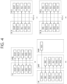
- a UE may determine SL transmission resource(s) within SL resource(s) configured by a base station/network or pre-configured SL resource(s).
- the configured SL resource(s) or the pre-configured SL resource(s) may be a resource pool.
- the UE may autonomously select or schedule resource(s) for SL transmission.
- the UE may perform SL communication by autonomously selecting resource(s) within the configured resource pool.
- the UE may autonomously select resource(s) within a selection window by performing a sensing procedure and a resource (re)selection procedure.
- the sensing may be performed in a unit of subchannel(s).
- a first UE which has selected resource(s) from a resource pool by itself may transmit a PSCCH (e.g., sidelink control information (SCI) or 1 st-stage SCI) to a second UE by using the resource(s).
- the first UE may transmit a PSSCH (e.g., 2nd-stage SCI, MAC PDU, data, etc.) related to the PSCCH to the second UE.
- the first UE may receive a PSFCH related to the PSCCH/PSSCH from the second UE.
- the higher layer can request the UE to determine a subset of resources from which the higher layer will select resources for PSSCH/PSCCH transmission. To trigger this procedure, in slot n, the higher layer provides the following parameters for this PSSCH/PSCCH transmission:
- sl-SelectionWindowList internal parameter T 2 min is set to the corresponding value from higher layer parameter sl-SelectionWindowList for the given value of prio TX .
- the resource reservation interval, P rsvp_TX if provided, is converted from units of msec to units of logical slots, resulting in P rsvp_TX ′ .
- t ′ 0 SL , t ′ 1 SL , t ′ 2 SL , ... may denote the set of slots which belongs to the sidelink resource pool.
- the UE shall assume that any set of L subCH contiguous sub-channels included in the corresponding resource pool within the time interval [ n + T 1 , n + T 2 ] correspond to one candidate single-slot resource, where - selection of T 1 is up to UE implementation under 0 ⁇ T 1 ⁇ T proc , 1 SL , where T proc , 1 SL is defined in slots in Table 8.1.4-2 where ⁇ SL is the SCS configuration of the SL BWP, - if T 2 min is shorter than the remaining packet delay budget (in slots) then T 2 is up to UE implementation subject to T 2 min ⁇ T 2 ⁇ remaining packet delay budget (in slots); otherwise T 2 is set to the remaining packet delay budget (in slots).
- the total number of candidate single-slot resources is denoted by M total .
- the sensing window is defined by the range of slots n ⁇ T 0 , n ⁇ T proc , 0 SL where T 0 is defined above and T proc , 0 SL is defined in slots in Table 8.1.4-1 where ⁇ SL is the SCS configuration of the SL BWP.
- the UE shall monitor slots which belongs to a sidelink resource pool within the sensing window except for those in which its own transmissions occur. The UE shall perform the behaviour in the following steps based on PSCCH decoded and RSRP measured in these slots.
- the set S A is initialized to the set of all the candidate single-slot resources.
- the UE shall exclude any candidate single-slot resource R x,y from the set S A if it meets all the following conditions: - the UE has not monitored slot t ' m SL in Step 2.
- condition c in step 6 would be met. 5a) If the number of candidate single-slot resources R x,y remaining in the set S A is smaller than X ⁇ M total , the set S A is initialized to the set of all the candidate single-slot resources as in step 4.
- the UE shall exclude any candidate single-slot resource R x,y from the set S A if it meets all the following conditions: a) the UE receives an SCI format 1-A in slot t ' m SL , and 'Resource reservation period' field, if present, and 'Priority' field in the received SCI format 1-A indicate the values P rsvp_RX and prio RX , respectively according to Clause 16.4 in [6, TS 38.213]; b) the RSRP measurement performed, according to clause 8.4.2.1 for the received SCI format 1-A, is higher than Th ( prio RX ,prio TX ); c) the SCI format received in slot t ' m SL or the same SCI format which, if and only if the 'Resource reservation period' field is present in the received SCI format 1-A, is assumed to be received in slot(s) t ' m + q ⁇ P rsvp _ RX ′
- T scal is set to selection window size T 2 converted to units of msec. 7) If the number of candidate single-slot resources remaining in the set S A is smaller than X ⁇ M total , then Th ( p i ,p j ) is increased by 3 dB for each priority value Th ( p i ,p j ) and the procedure continues with step 4.
- the UE shall report set S A to higher layers. If a resource r i from the set ( r 0 , r 1 , r 2 , ...) is not a member of S A , then the UE shall report re-evaluation of the resource r i to higher layers.
- a resource r i ′ from the set r 0 ′ , r 1 ′ , r 2 ′ , ... meets the conditions below then the UE shall report pre-emption of the resource r i ′ to higher layers - r i ′ is not a member of S A , and - r i ′ meets the conditions for exclusion in step 6, with Th ( prio RX , prio TX ) set to the final threshold after executing steps 1)-7), i.e.
- the UE shall exclude any candidate single-subframe resource R x,y from the set S A if it meets all the following conditions: - the UE receives an SCI format 1 in subframe t m SL , and "Resource reservation" field and "Priority" field in the received SCI format 1 indicate the values P rsvp_RX and prio RX , respectively. - PSSCH-RSRP measurement according to the received SCI format 1 is higher than Th prio TX , prio RX .
- SCI format 2-B is used for the decoding of PSSCH, with HARQ operation when HARQ-ACK information includes only NACK, or when there is no feedback of HARQ-ACK information.
- a method of transmitting a downlink signal through an unlicensed band will be described.
- a method of transmitting a downlink signal through an unlicensed band may be applied to a method of transmitting a sidelink signal through an unlicensed band.
- the base station may perform one of the following channel access procedures (e.g., CAP) for downlink signal transmission in an unlicensed band.
- CAP channel access procedures
- the length of a time duration spanned by sensing slots sensed to be idle before transmission(s) may be random.
- the type 1 DL CAP may be applied to the following transmissions:
- FIG. 13 shows CAP operations performed by a base station to transmit a downlink signal through an unlicensed band, based on an embodiment of the present disclosure.
- the embodiment of FIG. 13 may be combined with various embodiments of the present disclosure.
- Table 13 shows that m p , a minimum contention window (CW), a maximum CW, a maximum channel occupancy time (MCOT), and an allowed CW size, which are applied to the CAP, vary depending on channel access priority classes.
- Channel Access Priority Class (p) m p CW min,p CW max,p T mcot,p allowed CW p sizes 1 1 3 7 2 ms ⁇ 3,7 ⁇ 2 1 7 15 3 ms ⁇ 7,15 ⁇ 3 3 15 63 8 or 10 ms ⁇ 15,31,63 ⁇ 4 7 15 1023 8 or 10 ms ⁇ 15,31,63,127,255,511,1023 ⁇
- a contention window size (CWS), a maximum COT value, etc. for each CAPC may be defined.
- the defer duration T d is configured in the following order: duration T f (16 us) + m p consecutive sensing slot durations T sl (9 us).
- T f includes the sensing slot duration T sl at the beginning of the 16 us duration.
- HARQ-ACK feedback e.g., the ratio of ACK or NACK
- CW p may be initialized to CW min,p based on the HARQ-ACK feedback for the previous DL burst.
- CW p may be increased to the next higher allowed value or maintained as it is.
- the length of a time duration spanned by sensing slots sensed to be idle before transmission(s) may be determined.
- the type 2 DL CAP is classified into type 2A/2B/2C DL CAPs.
- the type 2A DL CAP may be applied to the following transmissions.
- the type 2B DL CAP is applicable to transmission(s) performed by the base station after a gap of 16 us from transmission(s) by the UE within a shared channel occupancy time.
- T f includes a sensing slot within 9 us from the end of the duration.
- the type 2C DL CAP is applicable to transmission(s) performed by the base station after a maximum of 16 us from transmission(s) by the UE within the shared channel occupancy time. In the type 2C DL CAP, the base station does not perform channel sensing before performing transmission.
- a method of transmitting an uplink signal through an unlicensed band will be described.
- a method of transmitting an uplink signal through an unlicensed band may be applied to a method of transmitting a sidelink signal through an unlicensed band.
- the UE may perform type 1 or type 2 CAP for UL signal transmission in an unlicensed band.
- the UE may perform the CAP (e.g., type 1 or type 2) configured by the base station for UL signal transmission.
- a UL grant scheduling PUSCH transmission (e.g., DCI formats 0_0 and 0_1) may include CAP type indication information for the UE.
- the length of a time duration spanned by sensing slots sensed to be idle before transmission(s) is random.
- the type 1 UL CAP may be applied to the following transmissions.
- FIG. 14 shows type 1 CAP operations performed by a UE to transmit an uplink signal, based on an embodiment of the present disclosure.
- the embodiment of FIG. 14 may be combined with various embodiments of the present disclosure.
- the UE may sense whether a channel is idle for sensing slot durations of a defer duration T d . Then, if a counter N is zero, the UE may perform transmission (S234). In this case, the UE may adjust the counter N by sensing the channel for additional sensing slot duration(s) according to the following steps:
- Table 14 shows that m p , a minimum CW, a maximum CW, a maximum channel occupancy time (MCOT), and an allowed CW size, which are applied to the CAP, vary depending on channel access priority classes.
- Channel Access Priority Class (p) m p CW min,p CW max,p T ulmcot,p allowed CW p sizes 1 2 3 7 2ms ⁇ 3,7 ⁇ 2 2 7 15 4 ms ⁇ 7,15 ⁇ 3 3 15 1023 6 or 10 ms ⁇ 15,31,63,127,255,511,1023 ⁇ 4 7 15 1023 6 or 10 ms ⁇ 15,31,63,127,255,511,1023 ⁇ 4 7 15 1023 6 or 10 ms ⁇ 15,31,63,127,255,511,1023 ⁇
- a contention window size (CWS), a maximum COT value, etc. for each CAPC may be defined.
- the defer duration T d is configured in the following order: duration T f (16 us) + m p consecutive sensing slot durations T sl (9 us).
- T f includes the sensing slot duration T sl at the beginning of the 16 us duration.
- CW p may be initialized to CW min,p based on the explicit/implicit reception response for the previous UL burst.
- CW p may be increased to the next higher allowed value or maintained as it is.
- the length of a time duration spanned by sensing slots sensed to be idle before transmission(s) may be determined.
- the type 2 UL CAP is classified into type 2A/2B/2C UL CAPs.
- T f includes a sensing slot at the beginning thereof.
- T f includes a sensing slot within 9 us from the end of the duration.
- the UE does not perform channel sensing before performing transmission.
- the UE having uplink data to be transmitted may select a CAPC mapped to 5QI of data, and the UE may perform the NR-U operation by applying parameters of the corresponding CACP (e.g., minimum contention window size, maximum contention window size, m p , etc.).
- the UE may select a backoff counter (BC) after selecting a random value between the minimum CW and the maximum CW mapped to the CAPC.
- the BC may be a positive integer less than or equal to the random value.
- the UE sensing a channel decreases the BC by 1 if the channel is idle.
- T sl 9 usec
- T f 16 usec
- the UE may transmit data by performing the type 2 LBT (e.g., type 2A LBT, type 2B LBT, or type 2C LBT) within COT.
- type 2 LBT e.g., type 2A LBT, type 2B LBT, or type 2C LBT
- the type 2A (also referred to as Cat-2 LBT (one shot LBT) or one-shot LBT) may be 25 usec one-shot LBT.
- transmission may start immediately after idle sensing for at least a 24 usec gap.
- the type 2A may be used to initiate transmission of SSB and non-unicast DL information. That is, the UE may sense a channel for 25 usec within COT, and if the channel is idle, the UE may attempt to transmit data by occupying the channel.
- the type 2B may be 16 usec one-shot LBT.
- transmission may start immediately after idle sensing for a 16 usec gap. That is, the UE may sense a channel for 16 usec within COT, and if the channel is idle, the UE may attempt to transmit data by occupying the channel.
- LBT may not be performed.
- transmission may start immediately after a gap of up to 16 usec and a channel may not be sensed before the transmission.
- the duration of the transmission may be up to 584 usec.
- the UE may attempt transmission after 16 usec without sensing, and the UE may perform transmission for up to 584 usec.
- the UE may perform a channel access operation based on Listen Before Talk (LBT). Before the UE accesses a channel in an unlicensed band, the UE should check whether the channel to be accessed is idle (e.g., a state in which UEs do not occupy the channel, a state in which UEs can access the corresponding channel and transmit data) or busy (e.g., a state in which the channel is occupied and data transmission/reception is performed on the corresponding channel, and the UE attempting to access the channel cannot transmit data while the channel is busy). That is, the operation in which the UE checks whether the channel is idle or busy may be referred to as Clear Channel Assessment (CCA), and the UE may check whether the channel is idle or busy for the CCA duration.
- CCA Clear Channel Assessment
- the following describes a UE procedure to report HARQ-ACK on a sidelink.
- a UE may be instructed by SCI format that schedules a reception of PSSCH on one or more subchannels from N PSSCH subch to transmit a PSFCH that includes HARQ-ACK information in response to the reception of a PSSCH.
- a UE provides HARQ-ACK information including ACK or NACK, or NACK only.
- a UE may be provided with the number of slots in a resource pool for PSFCH transmission occasion resources by sl-PSFCH-Period-r16. If the number is zero, PSFCH transmission from a UE is disabled in the resource pool.
- a UE may be instructed by the upper layer not to transmit a PSFCH in response to the reception of a PSSCH. If a UE receives a PSSCH in the resource pool and the HARQ feedback enabled/disabled indicator field included in the associated SCI format 2-A or SCI format 2-B has a value of 1, the UE provides HARQ-ACK information via PSFCH transmission from in resource pool.
- a UE transmits the PSFCH in a first slot, wherein the first slot is the slot including a PSFCH resource and after the minimum number of slots provided by sl-MinTimeGapPSFCH-r16 of the resource pool after the last slot of the PSSCH reception.
- a UE is provided by sl-PSFCH-RB-Set-r16 with M PSFCH PRB,set of PRBs in a resource pool for PSFCH transmissions on PRBs in the resource pool.
- M PSFCH PRB the number of PSSCH slots related to a PSFCH slot that is less than or equal to N subch and N PSFCH PSSCH , the number of subchannels for the resource pool provided by sl-NumSubchannel.
- a UE allocates the PRB [(i+j-N PSFCH PSSCH )-M PSFCH subch,slot , (i+1+j-N PSFCH PSSCH )-M PSFCH subch,slot -1] among the M PRB, set PSFCH PRB for slot i and subchannel j among the PSSCH slots associated with the PSFCH slot.
- M PSFCH subch,slot M PSFCH PRB,set / (N subch - NPSFCH PSSCH ), 0 ⁇ i ⁇ N PSFCH PSSCH , 0 ⁇ j ⁇ N subch , and the allocations starts in ascending order for i and continues in ascending order for j.
- a UE expects M PSFCH PRB,set to be a multiple of N subch ⁇ N PSFCH PSSCH .
- N PSFCH CS may be the number of cyclic shift pairs for the resource pool, and based on an indication by the higher layer,
- a PSFCH resource is indexed first in ascending order of a PRB indexes among N PSFCH type M PSFCH subch,slot PRBs, after then, it is indexed in ascending order of cyclic shift pair indexes among N PSFCH CS cyclic shift pairs.
- a UE determines an index of a PSFCH resource for a PSFCH transmission in response to the PSSCH reception as (P ID + M ID ) mod R PSFCH PRB,CS .
- P ID is a physical layer source ID provided by SCI format 2-A or 2-B scheduling a PSSCH reception
- M ID is an ID of a UE receiving a PSSCH, indicated from the higher layer when a UE detects SCI format 2-A in which a cast type indicator field value is "01”, M ID is 0 otherwise.
- a UE determines m 0 value for calculating a cyclic shift ⁇ value from N PSFCH CS and a cyclic shift pair index which corresponds to a PSFCH resource index using Table 15.
- an LBT operation may be performed to secure transmission opportunities in an unlicensed band.
- An LBT operation is an operation that performs channel sensing in a certain interval (contention window) in front of the resource on which transmission is to be attempted, and then performs transmission based on that resource only if it is idle.
- the LBT operation may be performed in units of RB sets.
- PSFCH may be performed in multiple PSFCH occasions to increase the probability of successful transmission.
- a UE may perform a sidelink transmission and/or reception operation in an unlicensed band.
- a UE's transmission may be preceded by a channel sensing operation (e.g., energy detection/measurement) for the channel to be used
- a UE may perform a transmission in the unlicensed band only if, as a result of the channel sensing, the channel or RB set to be used is determined to be IDLE (e.g., if the measured energy is less than or equal to or greater than a certain threshold value), and, if, according to a result of the channel sensing, the channel or RB set to be used is determined to be BUSY (e.g., if the measured energy is greater than or equal to or greater than a certain threshold value), the UE may cancel all or part of the transmission in the unlicensed band.
- IDLE e.g., if the measured energy is less than or equal to or greater than a certain threshold value
- BUSY e.g., if the measured energy
- the size and/or power spectral density (PSD) of the time interval and/or frequency occupied region of the signal/channel transmitted by the UE may be greater than or equal to a certain level, respectively.
- COT interval information that the channel obtained through initial general channel sensing is occupied for a certain period of time, and the length of the COT interval may be configured to have different maximum values depending on the priority of the service or data packet or the channel access priority class (CAPC).
- COT channel occupancy time
- the sidelink transmission may be transmitted through a plurality of RBs that are spaced apart.
- a UE may be provided from a base station with information about a single or multiple RB set(s) and a single or multiple interlaces, and the final transmission resource may be determined as the intersection of the RBs within the provided RB set(s) and the RBs corresponding to the provided interlaces.
- an interlace may be defined in a common RB (CRB) grid.
- CRB common RB
- the interlace index of each interlace may be determined based on the RB offset based on CRB #0.
- sensing and/or resource (re)selection is performed in a unit of subchannels in the case of sidelink communication, it may be required that the subchannels are represented in the form of interlaces and/or RB sets. In this way, subchannel-based sensing operations and/or resource reservation methods may be reused as much as possible.
- the embodiments for 60 kHz SCS may be extended and applied to SCS other than 15 kHz and/or 30 kHz SCS. In various embodiments of the disclosure, the embodiments for 60 kHz SCS may be extended and applied to 15 kHz and/or 30 kHz SCS.
- a subchannel with some component PRBs located outside the RB set may be used as a transmission resource when transmitting PSCCH/PSSCH.
- a UE may only use PRBs included within the RB set among the PRBs comprising the subchannel. For example, the above scheme may be the case where the RB set connected to the RB set is not included in the transmission resources.
- the UE may use at least the minimum number of component PRBs to meet the OCB requirements as transmission resources. For example, when calculating the TBS for the additionally used subchannel, the UE may exclude the resources of the subchannel when calculating the number of PRBs. For example, when calculating the TBS for the additionally used subchannel, the UE may include the resources of the subchannel when calculating the number of PRBs, assuming that the entire component PRB is used.
- a discontinuous PRB set when transmitting an SL channel, may be used as a transmission resource.
- the PRB gap within the discontinuous PRB set may be (pre-)configured.
- the RB indices of the first PRB set may be in the form 0, 2, 4, 6, ...
- the RB indices of the second PRB set may be in the form 1, 3, 5, ....
- the RB indices of the first PRB set may be in the form 0, 3, 6, 9, ...
- the RB indices of the second PRB set may be in the form 1, 4, 7, ...
- the RB indices of the third PRB set may be in the form 2, 5, 8, ....
- the transmit power may be maximized according to the PSD requirements, but the scheduling flexibility may be reduced due to the reduced amount of resources that can be separated.
- the discontinuous PRB set may include two PRBs that satisfy at least the OCB requirement.
- the PRB set may include at least an RB index N and an RB index N+M.
- the value of the M may be (pre-)configured to satisfy the OCB requirement.
- the value of M may be a minimum value of a value that satisfies the OCB requirement.
- the size of the RB set is P
- the value of M may be a value that is a raised value of P*0.8 minus 1.
- the value of N may be a set of values such that both N and N+M exist within a specific RB set.
- the number of values of N may be a rounding value of P-0.8*P or a discard value of 0.2*P, or may be less than the above values.
- the number of N or the candidate values of N may be (pre-)configured per resource pool and/or per SL channel.
- the UE may further include an additional PRB to overcome the transmit power limitation according to the PSD requirement.
- the PRBs comprising the RB set may be divided into a plurality of RB subsets each having a number P-0.8*P rounded up or 0.2*P rounded down, and the discontinuous PRB set may be organized in such a way as to include one RB from each RB subset for all or some of the RB subsets.
- the PRB gap between the RB subsets may be zero or a non-zero integer value, and the presence and value of the PRB gap may be configured differently depending on the size of the RB set.
- the discontinuous PRB set may comprise an RB index N, a discard value of N+0.2*P, (a discard value of N+0.2*P)*2, ..., N+M.
- the scheme for deriving the RB for the PSFCH from the subchannel index of the PSSCH and the PSSCH slot index may be extended to derive the PRB set for the PSFCH.
- a UE may use a single or a plurality of common RBs for the actual transmission in addition to the PSFCH RBs (for SL HARQ-ACK feedback) to meet the OCB requirements.
- a UE may use the minimum number of common RBs for a transmission to satisfy the OCB requirements.
- the selected common RB(s) (or its location) may be different depending on the location of the actual PSFCH RB(s) mentioned above. For example, if the OCB requirement is met when the UE transmits a plurality of PSFCHs, no additional common RBs may be used for the transmission.
- the actual maximum number of simultaneously transmittable PSFCH transmissions may change to N-M if the UE uses M common RBs for transmission.
- the actual maximum number of PSFCH transmissions that can be simultaneously transmitted may change to N-(number of RBs comprising the interlace)*M if the UE uses M common RBs for transmission.
- the UE may select as transmission targets by prioritizing combinations of PSFCH transmissions that meet the OCB requirements over selections based on individual PSFCH SL priorities.
- a UE when selecting the PSFCHs to transmit, a UE may select as transmission targets by prioritizing the combination of PSFCH transmissions that minimizes the number of common RBs used to satisfy the OCB requirements over the selection based on the priority of each PSFCH. For example, the UE may select the PSFCHs to transmit based on the required number of common RBs.
- the UE may allocate a minimum amount of power (e.g., a (pre-)configured power value or a power value according to a (pre-)configured ratio) of the total transmit power for or per common RB(s), and distribute the remaining transmit power equally to the PSFCH transmissions (for SL HARQ-ACK feedback).
- a UE may preferentially allocate the entire transmit power to the PSFCH transmission (for SL HARQ-ACK feedback) and then allocate the remaining transmit power for or per common RB(s).
- FIG. 15 shows a common PRB used to satisfy PSD requirements, according to one embodiment of the present disclosure.
- the embodiment of FIG. 15 may be combined with various embodiments of the present disclosure.
- a common PRB, a first dedicated PRB, and a second dedicated PRB are shown within a band of 1 MHz.
- the first dedicated PRB and the second dedicated PRB may be resources for PSFCH transmissions.
- the common PRB, the first dedicated PRB, and the second dedicated PRB may be resources in an interlaced structure, although simplified in FIG. 15 .
- the common PRB may be a resource of a single interlace (e.g., a common interlace).
- the first dedicated PRB and the second dedicated PRB may be PRBs that are included in the same interlace (e.g., first interlace).
- the transmit power related to the transmission performed through the common PRB may be a first transmit power
- the transmit power related to the transmission performed through the first dedicated PRB may be a second transmit power
- the transmit power related to the transmission performed through the second dedicated PRB may be a third transmit power.
- the sum of the first transmit power, the second transmit power, and the third transmit power may be limited to a certain value (e.g., 10 dB).
- the transmitting UE may fulfill the PSD requirement by reducing the first transmit power while maintaining the second transmit power and the third transmit power.
- the (corresponding) UE may omit the transmission of the common PRB.
- FIG. 16 shows a common PRB used to satisfy PSD requirements, according to one embodiment of the present disclosure.
- the embodiment of FIG. 16 may be combined with various embodiments of the present disclosure.
- a common PRB, a first dedicated PRB, and a second dedicated PRB are shown within a band of 1 MHz.
- the first dedicated PRB and the second dedicated PRB may be resources for PSFCH transmissions.
- the common PRB, the first dedicated PRB, and the second dedicated PRB may be resources in an interlace structure, although simplified in FIG. 16 .
- the common PRB may be a resource of a single interlace (e.g., a common interlace).
- the first dedicated PRB and the second dedicated PRB may be PRBs that are included in the same interlace (e.g., first interlace).
- a transmitting UE may omit transmission through the common PRB.
- the transmitting UE may only perform transmission through the at least one PRB for PSFCH transmission.
- a UE may use an additional common RB based interlace for actual transmission in addition to a PSFCH RB (for SL HARQ-ACK feedback).
- the common RB-based interlace may not be used for the actual transmission, and/or only a subset of the RBs comprising the common RB-based interlace may be used for the actual transmission.
- the location of the RBs comprising the common RB-based interlace used for transmission may be different.
- the maximum number of simultaneous PSFCH transmissions that can be transmitted may be different when a UE is transmitting a common RB-based interlace and when it is not.
- the actual maximum number of simultaneously transmittable PSFCHs may change to N-M (e.g., M is 1 or a specific value) when transmitting a common RB-based interlace.
- the UE may select the transmission target by prioritizing combinations of PSFCH transmissions that minimize the number of RBs used to form a common RB based interlace to satisfy the OCB requirement, over selections based on the priority of each PSFCH.
- the selection of the transmission target may be performed by preferentially considering a combination of PSFCH transmissions that minimizes the number of RBs that form a common RB-based interlace to satisfy the OCB requirement, over a selection based on the respective PSFCH priorities.
- a UE may select which PSFCHs to transmit based on the need for a common RB based interlace and/or the number of RBs comprising the common RB based interlace whose transmission is required.
- a UE may allocate a minimum amount of power (e.g., a (pre-)configured power value or a power value according to a (pre-)configured ratio) of the total transmit power to an interlace based on a common RB or per (actual transmitting) RB that constitutes an interlace based on a common RB, and distribute the remaining transmit power equally to PSFCH transmissions (for SL HARQ-ACK feedback).
- a minimum amount of power e.g., a (pre-)configured power value or a power value according to a (pre-)configured ratio
- the PSD for the PRB(s) used for SL HARQ-ACK feedback and the PSD for the other PRB(s) may be configured differently.
- the PSD for the PRB(s) used for SL HARQ-ACK feedback may be configured to be larger than the PSD for the other PRB(s).
- SL HARQ-ACK feedback signaling and common signaling for OCB requirements may overlap on the same PRB, which may require separate processing to avoid resource collisions.
- the cyclic shift value(s) that may be used for the PRB(s) used for SL HARQ-ACK feedback (according to ACK or NACK) and the cyclic shift value(s) that are (or may be) applied to the other PRB(s) may be distinguished. This may be to ensure that different sequences are distinguished, at least via CDM, when the same PRB is used by a specific UE for SL HARQ-ACK feedback transmission and by another UE for other purposes. For example, in the above, the UE may select a combination of cyclic shift values for the PRB(s) other than for SL HARQ-ACK feedback transmission, such that the PAPR for PSFCH transmission is lower.
- a UE may expect that the candidate set of PRBs used for SL HARQ-ACK feedback is (pre-)configured to belong to a specific interlace(s).
- the specific interlace(s) may be used by the UE for PSFCH transmission.
- the candidate set of PRBs used for SL HARQ-ACK feedback may be (pre-)configured to belong to a specific interlace(s).
- the information for the number of PRBs used for SL HARQ-ACK feedback and/or the PRB locations may be (pre-)configured. For example, if the number of PRBs used for the SL HARQ-ACK feedback is multiple, the UE may derive a second PRB from the first PRB after selecting a first PRB from the PSSCH resource corresponding to the SL HARQ-ACK feedback, and/or derive a plurality of PRBs from the PSSCH resource. For example, from the lowest PRB to the highest PRB of the PRBs used for the SL HARQ-ACK feedback may cover at least 2 MHz.
- the PSD may be maintained for PRBs belonging to the same subchannel or the same interlace or the same RB set.
- the PSD may be different on a unit of subchannel, unit of interlace, or unit of RB set.
- the PSD may be different in units of PSFCH PRBs or PSFCH transmissions.
- the sidelink transmit power may be scaled down (by the UE) according to the PSD requirements. For example, after the required transmit power for a single PSFCH is calculated, the sidelink transmit power may be scaled down (by the UE) according to the PSD requirements, and/or after the required transmit power for a plurality of PSFCH transmissions and the number of PSFCH transmissions that may be transmitted simultaneously may be determined (by the UE). For example, when adjusting the sidelink transmit power according to the above PSD requirements, the transmit power for the plurality of PSFCH transmissions may be scaled down equally. For example, when adjusting the sidelink transmit power according to the above PSD requirements, the transmit power for the plurality of PSFCH transmissions may be scaled down unequally on a unit of PSFCH transmissions and/or on a unit of RB sets.
- the UE may differently adjust and/or apply the nominal power (P0 value) and/or additional offset values.
- the RB index may be a PRB index, or may be a CRB index.
- each SL channel is not limited to the respective stated SL channel and may be extended and applied to different SL channels.
- the various schemes may be applied differently according to the size of the subcarrier space.
- the various schemes may be applied differently according to the type of sidelink channel.
- the various schemes may be applied differently according to the CAPC value and/or according to the SL priority value.
- the various schemes may be applied differently according to an RB set and/or according to the size of the RB set.
- the various schemes may be applied differently according to within the COT and/or outside the COT.
- a processor 202 of a receiving UE may configure at least one BWP. Then, the processor 202 of the receiving UE may control a transceiver 206 of the receiving UE to receive a sidelink-related physical channel and/or a sidelink-related reference signal from a transmitting UE on the at least one BWP.
- communication in an unlicensed band may be improved as OCB requirements may be satisfied by using a common PRB, and more reliable transmission operation based on HARQ feedback may be possible by prioritizing the power allocated to PSFCH transmissions that have practical meaning of transmission.
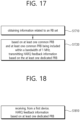
- FIG. 17 shows a procedure for a first device to perform wireless communication, according to one embodiment of the present disclosure.
- the embodiment of FIG. 17 may be combined with various embodiments of the present disclosure.
- a first device may obtain information related to a resource block, RB, set.
- the RB set may include a physical sidelink feedback channel, PSFCH, resource
- the PFSCH resource may include at least one dedicated physical resource block, PRB, and at least one common PRB, included within a bandwidth of 1 MHz.
- the first device may, based on the at least one dedicated PRB and the at least one common PRB being included within the bandwidth of 1 MHz, transmit hybrid automatic repeat request, HARQ, feedback information, based on the at least one dedicated PRB.
- the HARQ feedback information may be transmitted only through the at least one dedicated PRB.
- the at least one dedicated PRB may be included in the same interlace.
- a number of the at least one dedicated PRB may be 1, 2 or 5.
- the at least one common PRB may be included in one interlace.
- a plurality of cyclic shifts may be used in a plurality of PSFCH transmissions through the at least one dedicated PRB.
- the HARQ feedback information may be not transmitted through the at least one common PRB.
- a guard band may exist between the at least one dedicated PRB and the at least one common PRB.
- the first device may determine that total transmit power related to the first device exceeds maximum transmit power of the first device; and adjust transmit power for transmitting hybrid automatic repeat request, HARQ, feedback information based on the PSFCH resource. For example, transmit power related to the at least one common PRB may be reduced such that the total transmit power does not exceed the maximum transmit power.
- the maximum transmit power may be related to a power spectral density, PSD, requirement.
- the HARQ feedback information may be related to at least one physical sidelink shared channel, PSSCH, transmission.
- the HARQ feedback information may be transmitted based on an interval between the at least one dedicated PRB and the at least one common PRB being greater than a threshold value.
- a processor 102 of a first device 100 may obtain information related to a resource block, RB, set.
- the RB set may include a physical sidelink feedback channel, PSFCH, resource
- the PFSCH resource may include at least one dedicated physical resource block, PRB, and at least one common PRB, included within a bandwidth of 1 MHz.
- the processor 102 of the first device 100 may, based on the at least one dedicated PRB and the at least one common PRB being included within the bandwidth of 1 MHz, control a transceiver 106 to transmit hybrid automatic repeat request, HARQ, feedback information, based on the at least one dedicated PRB.
- a first device for performing wireless communication may comprise: at least one transceiver; at least one processor; and at least one memory operably connected to the at least one processor and storing instructions that, based on being executed by the at least one processor, cause the first device to perform operations.
- the operations may comprise: obtaining information related to a resource block, RB, set, wherein the RB set may include a physical sidelink feedback channel, PSFCH, resource, and wherein the PFSCH resource may include at least one dedicated physical resource block, PRB, and at least one common PRB, included within a bandwidth of 1 MHz; and based on the at least one dedicated PRB and the at least one common PRB being included within the bandwidth of 1 MHz, transmitting hybrid automatic repeat request, HARQ, feedback information, based on the at least one dedicated PRB.
- the RB set may include a physical sidelink feedback channel, PSFCH, resource
- the PFSCH resource may include at least one dedicated physical resource block, PRB, and at least one common PRB, included within a bandwidth of 1 MHz; and based on the at least one dedicated PRB and the at least one common PRB being included within the bandwidth of 1 MHz, transmitting hybrid automatic repeat request, HARQ, feedback information, based on the at least one dedicated PRB.
- the HARQ feedback information may be transmitted only through the at least one dedicated PRB.
- the at least one dedicated PRB may be included in the same interlace.
- a number of the at least one dedicated PRB may be 1, 2 or 5.
- the at least one common PRB may be included in one interlace.
- a plurality of cyclic shifts may be used in a plurality of PSFCH transmissions through the at least one dedicated PRB.
- the HARQ feedback information may be not transmitted through the at least one common PRB.
- a guard band may exist between the at least one dedicated PRB and the at least one common PRB.
- the operations may further comprise: determining that total transmit power related to the first device exceeds maximum transmit power of the first device; and adjusting transmit power for transmitting hybrid automatic repeat request, HARQ, feedback information based on the PSFCH resource. For example, transmit power related to the at least one common PRB may be reduced such that the total transmit power does not exceed the maximum transmit power.
- the maximum transmit power may be related to a power spectral density, PSD, requirement.
- the maximum transmit power may be 10dBm.
- the HARQ feedback information may be related to at least one physical sidelink shared channel, PSSCH, transmission.
- the HARQ feedback information may be transmitted based on an interval between the at least one dedicated PRB and the at least one common PRB being greater than a threshold value.
- a device adapted to control a first user equipment, UE may be proposed.
- the device may comprise: at least one processor; and at least one memory operably connected to the at least one processor and storing instructions that, based on being executed by the at least one processor, cause the first UE to perform operations.
- the operations may comprise: obtaining information related to a resource block, RB, set, wherein the RB set may include a physical sidelink feedback channel, PSFCH, resource, and wherein the PFSCH resource may include at least one dedicated physical resource block, PRB, and at least one common PRB, included within a bandwidth of 1 MHz; and based on the at least one dedicated PRB and the at least one common PRB being included within the bandwidth of 1 MHz, transmitting hybrid automatic repeat request, HARQ, feedback information, based on the at least one dedicated PRB.
- the RB set may include a physical sidelink feedback channel, PSFCH, resource
- the PFSCH resource may include at least one dedicated physical resource block, PRB, and at least one common PRB, included within a bandwidth of 1 MHz; and based on the at least one dedicated PRB and the at least one common PRB being included within the bandwidth of 1 MHz, transmitting hybrid automatic repeat request, HARQ, feedback information, based on the at least one dedicated PRB.
- a non-transitory computer-readable storage medium storing instructions may be proposed.
- the instructions based on being executed, may cause a first device to: obtain information related to a resource block, RB, set, wherein the RB set may include a physical sidelink feedback channel, PSFCH, resource, and wherein the PFSCH resource may include at least one dedicated physical resource block, PRB, and at least one common PRB, included within a bandwidth of 1 MHz; and based on the at least one dedicated PRB and the at least one common PRB being included within the bandwidth of 1 MHz, transmit hybrid automatic repeat request, HARQ, feedback information, based on the at least one dedicated PRB.
- HARQ hybrid automatic repeat request
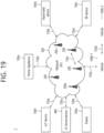
- FIG. 18 shows a procedure for a second device to perform wireless communication, according to one embodiment of the present disclosure.
- the embodiment of FIG. 18 may be combined with various embodiments of the present disclosure.
- a second device may receive, from a first device, hybrid automatic repeat request, HARQ, feedback information based on at least one dedicated physical resource block, PRB.
- the HARQ feedback information may be transmitted based on the at least one PRB from the first device based on the at least one dedicated PRB and at least one common PRB being included within a bandwidth of 1 MHz, and the at least one dedicated PRB and the at least one common PRB may be included in a physical sidelink feedback channel, PSFCH, resource.
- PSFCH physical sidelink feedback channel
- the HARQ feedback information may be transmitted only through the at least one dedicated PRB from the first device.
- a processor 202 of a second device 200 may control a transceiver 206 to receive, from a first device 100, hybrid automatic repeat request, HARQ, feedback information based on at least one dedicated physical resource block, PRB.
- the HARQ feedback information may be transmitted based on the at least one PRB from the first device 100 based on the at least one dedicated PRB and at least one common PRB being included within a bandwidth of 1 MHz, and the at least one dedicated PRB and the at least one common PRB may be included in a physical sidelink feedback channel, PSFCH, resource.
- a second device for performing wireless communication may comprise: at least one transceiver; at least one processor; and at least one memory operably connected to the at least one processor and storing instructions that, based on being executed by the at least one processor, cause the second device to perform operations.
- the operations may comprise: receiving, from a first device, hybrid automatic repeat request, HARQ, feedback information based on at least one dedicated physical resource block, PRB, wherein the HARQ feedback information may be transmitted based on the at least one PRB from the first device based on the at least one dedicated PRB and at least one common PRB being included within a bandwidth of 1 MHz, and wherein the at least one dedicated PRB and the at least one common PRB may be included in a physical sidelink feedback channel, PSFCH, resource.
- PSFCH physical sidelink feedback channel
- FIG. 19 shows a communication system 1, based on an embodiment of the present disclosure.
- the embodiment of FIG. 19 may be combined with various embodiments of the present disclosure.
- a communication system 1 to which various embodiments of the present disclosure are applied includes wireless devices, Base Stations (BSs), and a network.
- the wireless devices represent devices performing communication using Radio Access Technology (RAT) (e.g., 5G New RAT (NR)) or Long-Term Evolution (LTE)) and may be referred to as communication/radio/5G devices.
- RAT Radio Access Technology
- the wireless devices may include, without being limited to, a robot 100a, vehicles 100b-1 and 100b-2, an eXtended Reality (XR) device 100c, a hand-held device 100d, a home appliance 100e, an Internet of Things (IoT) device 100f, and an Artificial Intelligence (AI) device/server 400.
- RAT Radio Access Technology
- NR 5G New RAT
- LTE Long-Term Evolution
- the wireless devices may include, without being limited to, a robot 100a, vehicles 100b-1 and 100b-2, an eXtended Reality (XR) device 100c, a hand-held device 100d
- the vehicles may include a vehicle having a wireless communication function, an autonomous vehicle, and a vehicle capable of performing communication between vehicles.
- the vehicles may include an Unmanned Aerial Vehicle (UAV) (e.g., a drone).
- UAV Unmanned Aerial Vehicle
- the XR device may include an Augmented Reality (AR)/Virtual Reality (VR)/Mixed Reality (MR) device and may be implemented in the form of a Head-Mounted Device (HMD), a Head-Up Display (HUD) mounted in a vehicle, a television, a smartphone, a computer, a wearable device, a home appliance device, a digital signage, a vehicle, a robot, etc.
- the hand-held device may include a smartphone, a smartpad, a wearable device (e.g., a smartwatch or a smartglasses), and a computer (e.g., a notebook).
- the home appliance may include a TV, a refrigerator, and a washing machine.
- the IoT device may include a sensor and a smartmeter.
- the BSs and the network may be implemented as wireless devices and a specific wireless device 200a may operate as a BS/network node with respect to other wireless devices.
- wireless communication technology implemented in wireless devices 100a to 100f of the present disclosure may include Narrowband Internet of Things for low-power communication in addition to LTE, NR, and 6G.
- NB-IoT technology may be an example of Low Power Wide Area Network (LPWAN) technology and may be implemented as standards such as LTE Cat NB1, and/or LTE Cat NB2, and is not limited to the name described above.
- the wireless communication technology implemented in the wireless devices 100a to 100f of the present disclosure may perform communication based on LTE-M technology.
- the LTE-M technology may be an example of the LPWAN and may be called by various names including enhanced Machine Type Communication (eMTC), and the like.
- eMTC enhanced Machine Type Communication
- the LTE-M technology may be implemented as at least any one of various standards such as 1) LTE CAT 0, 2) LTE Cat M1, 3) LTE Cat M2, 4) LTE non-Bandwidth Limited (non-BL), 5) LTE-MTC, 6) LTE Machine Type Communication, and/or 7) LTE M, and is not limited to the name described above.
- the wireless communication technology implemented in the wireless devices 100a to 100f of the present disclosure may include at least one of Bluetooth, Low Power Wide Area Network (LPWAN), and ZigBee considering the low-power communication, and is not limited to the name described above.
- the ZigBee technology may generate personal area networks (PAN) related to small/low-power digital communication based on various standards including IEEE 802.15.4, and the like, and may be called by various names.
- PAN personal area networks
- the wireless devices 100a to 100f may be connected to the network 300 via the BSs 200.
- An AI technology may be applied to the wireless devices 100a to 100f and the wireless devices 100a to 100f may be connected to the AI server 400 via the network 300.
- the network 300 may be configured using a 3G network, a 4G (e.g., LTE) network, or a 5G (e.g., NR) network.
- the wireless devices 100a to 100f may communicate with each other through the BSs 200/network 300, the wireless devices 100a to 100f may perform direct communication (e.g., sidelink communication) with each other without passing through the BSs/network.
- the vehicles 100b-1 and 100b-2 may perform direct communication (e.g.
- V2VyVehicle-to-everything (V2X) communication Vehicle-to-Vehicle (V2VyVehicle-to-everything (V2X) communication).
- the IoT device e.g., a sensor
- the IoT device may perform direct communication with other IoT devices (e.g., sensors) or other wireless devices 100a to 100f.
- Wireless communication/connections 150a, 150b, or 150c may be established between the wireless devices 100a to 100f/BS 200, or BS 200/BS 200.
- the wireless communication/connections may be established through various RATs (e.g., 5G NR) such as uplink/downlink communication 150a, sidelink communication 150b (or, D2D communication), or inter BS communication (e.g. relay, Integrated Access Backhaul (IAB)).
- the wireless devices and the BSs/the wireless devices may transmit/receive radio signals to/from each other through the wireless communication/connections 150a and 150b.
- the wireless communication/connections 150a and 150b may transmit/receive signals through various physical channels.
- various configuration information configuring processes various signal processing processes (e.g., channel encoding/decoding, modulation/demodulation, and resource mapping/demapping), and resource allocating processes, for transmitting/receiving radio signals, may be performed based on the various proposals of the present disclosure.
- various signal processing processes e.g., channel encoding/decoding, modulation/demodulation, and resource mapping/demapping
- resource allocating processes for transmitting/receiving radio signals
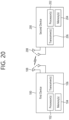
- FIG. 20 shows wireless devices, based on an embodiment of the present disclosure.
- the embodiment of FIG. 20 may be combined with various embodiments of the present disclosure.
- a first wireless device 100 and a second wireless device 200 may transmit radio signals through a variety of RATs (e.g., LTE and NR).
- ⁇ the first wireless device 100 and the second wireless device 200 ⁇ may correspond to ⁇ the wireless device 100x and the BS 200 ⁇ and/or ⁇ the wireless device 100x and the wireless device 100x ⁇ of FIG. 19 .
- the first wireless device 100 may include one or more processors 102 and one or more memories 104 and additionally further include one or more transceivers 106 and/or one or more antennas 108.
- the processor(s) 102 may control the memory(s) 104 and/or the transceiver(s) 106 and may be configured to implement the descriptions, functions, procedures, proposals, methods, and/or operational flowcharts disclosed in this document.
- the processor(s) 102 may process information within the memory(s) 104 to generate first information/signals and then transmit radio signals including the first information/signals through the transceiver(s) 106.
- the processor(s) 102 may receive radio signals including second information/signals through the transceiver 106 and then store information obtained by processing the second information/signals in the memory(s) 104.
- the memory(s) 104 may be connected to the processor(s) 102 and may store a variety of information related to operations of the processor(s) 102.
- the memory(s) 104 may store software code including commands for performing a part or the entirety of processes controlled by the processor(s) 102 or for performing the descriptions, functions, procedures, proposals, methods, and/or operational flowcharts disclosed in this document.
- the processor(s) 102 and the memory(s) 104 may be a part of a communication modem/circuit/chip designed to implement RAT (e.g., LTE or NR).
- the transceiver(s) 106 may be connected to the processor(s) 102 and transmit and/or receive radio signals through one or more antennas 108.
- Each of the transceiver(s) 106 may include a transmitter and/or a receiver.
- the transceiver(s) 106 may be interchangeably used with Radio Frequency (RF) unit(s).
- the wireless device may represent a communication modem/circuit/chip.
- the second wireless device 200 may include one or more processors 202 and one or more memories 204 and additionally further include one or more transceivers 206 and/or one or more antennas 208.
- the processor(s) 202 may control the memory(s) 204 and/or the transceiver(s) 206 and may be configured to implement the descriptions, functions, procedures, proposals, methods, and/or operational flowcharts disclosed in this document.
- the processor(s) 202 may process information within the memory(s) 204 to generate third information/signals and then transmit radio signals including the third information/signals through the transceiver(s) 206.
- the processor(s) 202 may receive radio signals including fourth information/signals through the transceiver(s) 106 and then store information obtained by processing the fourth information/signals in the memory(s) 204.
- the memory(s) 204 may be connected to the processor(s) 202 and may store a variety of information related to operations of the processor(s) 202.
- the memory(s) 204 may store software code including commands for performing a part or the entirety of processes controlled by the processor(s) 202 or for performing the descriptions, functions, procedures, proposals, methods, and/or operational flowcharts disclosed in this document.
- the processor(s) 202 and the memory(s) 204 may be a part of a communication modem/circuit/chip designed to implement RAT (e.g., LTE or NR).
- the transceiver(s) 206 may be connected to the processor(s) 202 and transmit and/or receive radio signals through one or more antennas 208.
- Each of the transceiver(s) 206 may include a transmitter and/or a receiver.
- the transceiver(s) 206 may be interchangeably used with RF unit(s).
- the wireless device may represent a communication modem/circuit/chip.
- the one or more processors 102 and 202 may generate messages, control information, data, or information according to the descriptions, functions, procedures, proposals, methods, and/or operational flowcharts disclosed in this document.
- the one or more processors 102 and 202 may generate signals (e.g., baseband signals) including PDUs, SDUs, messages, control information, data, or information according to the descriptions, functions, procedures, proposals, methods, and/or operational flowcharts disclosed in this document and provide the generated signals to the one or more transceivers 106 and 206.
- the one or more processors 102 and 202 may be referred to as controllers, microcontrollers, microprocessors, or microcomputers.
- the one or more processors 102 and 202 may be implemented by hardware, firmware, software, or a combination thereof.
- ASICs Application Specific Integrated Circuits
- DSPs Digital Signal Processors
- DSPDs Digital Signal Processing Devices
- PLDs Programmable Logic Devices
- FPGAs Field Programmable Gate Arrays
- the descriptions, functions, procedures, proposals, methods, and/or operational flowcharts disclosed in this document may be implemented using firmware or software and the firmware or software may be configured to include the modules, procedures, or functions.
- Firmware or software configured to perform the descriptions, functions, procedures, proposals, methods, and/or operational flowcharts disclosed in this document may be included in the one or more processors 102 and 202 or stored in the one or more memories 104 and 204 so as to be driven by the one or more processors 102 and 202.
- the descriptions, functions, procedures, proposals, methods, and/or operational flowcharts disclosed in this document may be implemented using firmware or software in the form of code, commands, and/or a set of commands.
- the one or more memories 104 and 204 may be connected to the one or more processors 102 and 202 and store various types of data, signals, messages, information, programs, code, instructions, and/or commands.
- the one or more memories 104 and 204 may be configured by Read-Only Memories (ROMs), Random Access Memories (RAMs), Electrically Erasable Programmable Read-Only Memories (EPROMs), flash memories, hard drives, registers, cash memories, computer-readable storage media, and/or combinations thereof.
- the one or more memories 104 and 204 may be located at the interior and/or exterior of the one or more processors 102 and 202.
- the one or more memories 104 and 204 may be connected to the one or more processors 102 and 202 through various technologies such as wired or wireless connection.
- the one or more transceivers 106 and 206 may transmit user data, control information, and/or radio signals/channels, mentioned in the methods and/or operational flowcharts of this document, to one or more other devices.
- the one or more transceivers 106 and 206 may receive user data, control information, and/or radio signals/channels, mentioned in the descriptions, functions, procedures, proposals, methods, and/or operational flowcharts disclosed in this document, from one or more other devices.
- the one or more transceivers 106 and 206 may be connected to the one or more processors 102 and 202 and transmit and receive radio signals.
- the one or more processors 102 and 202 may perform control so that the one or more transceivers 106 and 206 may transmit user data, control information, or radio signals to one or more other devices.
- the one or more processors 102 and 202 may perform control so that the one or more transceivers 106 and 206 may receive user data, control information, or radio signals from one or more other devices.
- the one or more transceivers 106 and 206 may be connected to the one or more antennas 108 and 208 and the one or more transceivers 106 and 206 may be configured to transmit and receive user data, control information, and/or radio signals/channels, mentioned in the descriptions, functions, procedures, proposals, methods, and/or operational flowcharts disclosed in this document, through the one or more antennas 108 and 208.
- the one or more antennas may be a plurality of physical antennas or a plurality of logical antennas (e.g., antenna ports).
- the one or more transceivers 106 and 206 may convert received radio signals/channels etc.
- the one or more transceivers 106 and 206 may convert the user data, control information, radio signals/channels, etc. processed using the one or more processors 102 and 202 from the base band signals into the RF band signals.
- the one or more transceivers 106 and 206 may include (analog) oscillators and/or filters.
- FIG. 21 shows a signal process circuit for a transmission signal, based on an embodiment of the present disclosure.
- the embodiment of FIG. 21 may be combined with various embodiments of the present disclosure.
- a signal processing circuit 1000 may include scramblers 1010, modulators 1020, a layer mapper 1030, a precoder 1040, resource mappers 1050, and signal generators 1060.
- An operation/function of FIG. 21 may be performed, without being limited to, the processors 102 and 202 and/or the transceivers 106 and 206 of FIG. 20 .
- Hardware elements of FIG. 21 may be implemented by the processors 102 and 202 and/or the transceivers 106 and 206 of FIG. 20 .
- blocks 1010 to 1060 may be implemented by the processors 102 and 202 of FIG. 20 .
- the blocks 1010 to 1050 may be implemented by the processors 102 and 202 of FIG. 20 and the block 1060 may be implemented by the transceivers 106 and 206 of FIG. 20 .
- Codewords may be converted into radio signals via the signal processing circuit 1000 of FIG. 21 .
- the codewords are encoded bit sequences of information blocks.
- the information blocks may include transport blocks (e.g., a UL-SCH transport block, a DL-SCH transport block).
- the radio signals may be transmitted through various physical channels (e.g., a PUSCH and a PDSCH).
- the codewords may be converted into scrambled bit sequences by the scramblers 1010.
- Scramble sequences used for scrambling may be generated based on an initialization value, and the initialization value may include ID information of a wireless device.
- the scrambled bit sequences may be modulated to modulation symbol sequences by the modulators 1020.
- a modulation scheme may include pi/2-Binary Phase Shift Keying (pi/2-BPSK), m-Phase Shift Keying (m-PSK), and m-Quadrature Amplitude Modulation (m-QAM).
- Complex modulation symbol sequences may be mapped to one or more transport layers by the layer mapper 1030.
- Modulation symbols of each transport layer may be mapped (precoded) to corresponding antenna port(s) by the precoder 1040.
- Outputs z of the precoder 1040 may be obtained by multiplying outputs y of the layer mapper 1030 by an N*M precoding matrix W.
- N is the number of antenna ports and M is the number of transport layers.
- the precoder 1040 may perform precoding after performing transform precoding (e.g., DFT) for complex modulation symbols. Alternatively, the precoder 1040 may perform precoding without performing transform precoding.
- transform precoding e.g., DFT
- the resource mappers 1050 may map modulation symbols of each antenna port to time-frequency resources.
- the time-frequency resources may include a plurality of symbols (e.g., a CP-OFDMA symbols and DFT-s-OFDMA symbols) in the time domain and a plurality of subcarriers in the frequency domain.
- the signal generators 1060 may generate radio signals from the mapped modulation symbols and the generated radio signals may be transmitted to other devices through each antenna.
- the signal generators 1060 may include Inverse Fast Fourier Transform (IFFT) modules, Cyclic Prefix (CP) inserters, Digital-to-Analog Converters (DACs), and frequency up-converters.
- IFFT Inverse Fast Fourier Transform
- CP Cyclic Prefix
- DACs Digital-to-Analog Converters
- Signal processing procedures for a signal received in the wireless device may be configured in a reverse manner of the signal processing procedures 1010 to 1060 of FIG. 21 .
- the wireless devices e.g., 100 and 200 of FIG. 20
- the received radio signals may be converted into baseband signals through signal restorers.
- the signal restorers may include frequency downlink converters, Analog-to-Digital Converters (ADCs), CP remover, and Fast Fourier Transform (FFT) modules.
- ADCs Analog-to-Digital Converters
- FFT Fast Fourier Transform
- the baseband signals may be restored to codewords through a resource demapping procedure, a postcoding procedure, a demodulation processor, and a descrambling procedure.
- a signal processing circuit for a reception signal may include signal restorers, resource demappers, a postcoder, demodulators, descramblers, and decoders.
- FIG. 22 shows another example of a wireless device, based on an embodiment of the present disclosure.
- the wireless device may be implemented in various forms according to a use-case/service (refer to FIG. 19 ).
- the embodiment of FIG. 22 may be combined with various embodiments of the present disclosure.
- wireless devices 100 and 200 may correspond to the wireless devices 100 and 200 of FIG. 20 and may be configured by various elements, components, units/portions, and/or modules.
- each of the wireless devices 100 and 200 may include a communication unit 110, a control unit 120, a memory unit 130, and additional components 140.
- the communication unit may include a communication circuit 112 and transceiver(s) 114.
- the communication circuit 112 may include the one or more processors 102 and 202 and/or the one or more memories 104 and 204 of FIG. 20 .
- the transceiver(s) 114 may include the one or more transceivers 106 and 206 and/or the one or more antennas 108 and 208 of FIG. 20 .
- the control unit 120 is electrically connected to the communication unit 110, the memory 130, and the additional components 140 and controls overall operation of the wireless devices. For example, the control unit 120 may control an electric/mechanical operation of the wireless device based on programs/code/commands/information stored in the memory unit 130.
- the control unit 120 may transmit the information stored in the memory unit 130 to the exterior (e.g., other communication devices) via the communication unit 110 through a wireless/wired interface or store, in the memory unit 130, information received through the wireless/wired interface from the exterior (e.g., other communication devices) via the communication unit 110.
- the additional components 140 may be variously configured according to types of wireless devices.
- the additional components 140 may include at least one of a power unit/battery, input/output (I/O) unit, a driving unit, and a computing unit.
- the wireless device may be implemented in the form of, without being limited to, the robot (100a of FIG. 19 ), the vehicles (100b-1 and 100b-2 of FIG. 19 ), the XR device (100c of FIG. 19 ), the hand-held device (100d of FIG. 19 ), the home appliance (100e of FIG. 19 ), the IoT device (100f of FIG.
- the wireless device may be used in a mobile or fixed place according to a use-example/service.
- the entirety of the various elements, components, units/portions, and/or modules in the wireless devices 100 and 200 may be connected to each other through a wired interface or at least a part thereof may be wirelessly connected through the communication unit 110.
- the control unit 120 and the communication unit 110 may be connected by wire and the control unit 120 and first units (e.g., 130 and 140) may be wirelessly connected through the communication unit 110.
- Each element, component, unit/portion, and/or module within the wireless devices 100 and 200 may further include one or more elements.
- the control unit 120 may be configured by a set of one or more processors.
- control unit 120 may be configured by a set of a communication control processor, an application processor, an Electronic Control Unit (ECU), a graphical processing unit, and a memory control processor.
- memory 130 may be configured by a Random Access Memory (RAM), a Dynamic RAM (DRAM), a Read Only Memory (ROM)), a flash memory, a volatile memory, a non-volatile memory, and/or a combination thereof.
- RAM Random Access Memory
- DRAM Dynamic RAM
- ROM Read Only Memory
- flash memory a volatile memory
- non-volatile memory and/or a combination thereof.
- FIG. 22 An example of implementing FIG. 22 will be described in detail with reference to the drawings.
- FIG. 23 shows a hand-held device, based on an embodiment of the present disclosure.
- the hand-held device may include a smartphone, a smartpad, a wearable device (e.g., a smartwatch or a smartglasses), or a portable computer (e.g., a notebook).
- the hand-held device may be referred to as a mobile station (MS), a user terminal (UT), a Mobile Subscriber Station (MSS), a Subscriber Station (SS), an Advanced Mobile Station (AMS), or a Wireless Terminal (WT).
- the embodiment of FIG. 23 may be combined with various embodiments of the present disclosure.
- a hand-held device 100 may include an antenna unit 108, a communication unit 110, a control unit 120, a memory unit 130, a power supply unit 140a, an interface unit 140b, and an I/O unit 140c.
- the antenna unit 108 may be configured as a part of the communication unit 110.
- Blocks 110 to 130/140a to140c correspond to the blocks 110 to 130/140 of FIG. 22 , respectively.
- the communication unit 110 may transmit and receive signals (e.g., data and control signals) to and from other wireless devices or BSs.
- the control unit 120 may perform various operations by controlling constituent elements of the hand-held device 100.
- the control unit 120 may include an Application Processor (AP).
- the memory unit 130 may store data/parameters/programs/code/commands needed to drive the hand-held device 100.
- the memory unit 130 may store input/output data/information.
- the power supply unit 140a may supply power to the hand-held device 100 and include a wired/wireless charging circuit, a battery, etc.
- the interface unit 140b may support connection of the hand-held device 100 to other external devices.
- the interface unit 140b may include various ports (e.g., an audio I/O port and a video I/O port) for connection with external devices.
- the I/O unit 140c may input or output video information/signals, audio information/signals, data, and/or information input by a user.
- the I/O unit 140c may include a camera, a microphone, a user input unit, a display unit 140d, a speaker, and/or a haptic module.
- the I/O unit 140c may acquire information/signals (e.g., touch, text, voice, images, or video) input by a user and the acquired information/signals may be stored in the memory unit 130.
- the communication unit 110 may convert the information/signals stored in the memory into radio signals and transmit the converted radio signals to other wireless devices directly or to a BS.
- the communication unit 110 may receive radio signals from other wireless devices or the BS and then restore the received radio signals into original information/signals.
- the restored information/signals may be stored in the memory unit 130 and may be output as various types (e.g., text, voice, images, video, or haptic) through the I/O unit 140c.
- FIG. 24 shows a vehicle or an autonomous vehicle, based on an embodiment of the present disclosure.
- the vehicle or autonomous vehicle may be implemented by a mobile robot, a car, a train, a manned/unmanned Aerial Vehicle (AV), a ship, etc.
- the embodiment of FIG. 24 may be combined with various embodiments of the present disclosure.
Landscapes
- Engineering & Computer Science (AREA)
- Signal Processing (AREA)
- Computer Networks & Wireless Communication (AREA)
- Mobile Radio Communication Systems (AREA)
Applications Claiming Priority (4)
| Application Number | Priority Date | Filing Date | Title |
|---|---|---|---|
| KR20220106312 | 2022-08-24 | ||
| KR20220126412 | 2022-10-04 | ||
| KR20220153098 | 2022-11-15 | ||
| PCT/KR2023/012504 WO2024043699A1 (ko) | 2022-08-24 | 2023-08-23 | 비면허 대역에서 점유 채널 대역폭 요구 사항을 고려한 nr 사이드링크 전송 방법 및 장치 |
Publications (1)
| Publication Number | Publication Date |
|---|---|
| EP4580280A1 true EP4580280A1 (de) | 2025-07-02 |
Family
ID=90013755
Family Applications (1)
| Application Number | Title | Priority Date | Filing Date |
|---|---|---|---|
| EP23857731.6A Pending EP4580280A1 (de) | 2022-08-24 | 2023-08-23 | Verfahren und vorrichtung zur übertragung von nr-sidelink unter berücksichtigung der bandbreitenanforderung eines besetzten kanals in einem unlizenzierten band |
Country Status (4)
| Country | Link |
|---|---|
| EP (1) | EP4580280A1 (de) |
| KR (1) | KR20250050882A (de) |
| CN (1) | CN119790702A (de) |
| WO (1) | WO2024043699A1 (de) |
Family Cites Families (3)
| Publication number | Priority date | Publication date | Assignee | Title |
|---|---|---|---|---|
| CN111865504B (zh) * | 2019-04-30 | 2024-08-02 | 北京三星通信技术研究有限公司 | 用于旁路通信的方法、接收设备和发送设备 |
| US12267169B2 (en) * | 2019-08-14 | 2025-04-01 | Hyundai Motor Company | Method and apparatus for transmitting and receiving HARQ response in communication system supporting sidelink communication |
| KR20220043538A (ko) * | 2020-09-29 | 2022-04-05 | 주식회사 아이티엘 | 무선 통신 시스템에서 자원을 선택하는 방법 및 장치 |
-
2023
- 2023-08-23 KR KR1020257004645A patent/KR20250050882A/ko active Pending
- 2023-08-23 WO PCT/KR2023/012504 patent/WO2024043699A1/ko not_active Ceased
- 2023-08-23 EP EP23857731.6A patent/EP4580280A1/de active Pending
- 2023-08-23 CN CN202380061295.0A patent/CN119790702A/zh active Pending
Also Published As
| Publication number | Publication date |
|---|---|
| KR20250050882A (ko) | 2025-04-15 |
| WO2024043699A1 (ko) | 2024-02-29 |
| CN119790702A (zh) | 2025-04-08 |
Similar Documents
| Publication | Publication Date | Title |
|---|---|---|
| EP4572502A1 (de) | Verfahren und vorrichtung zur durchführung eines kanalzugriffs für psfch-übertragung in einem unlizenzierten band | |
| EP4498745A1 (de) | Verfahren und vorrichtung zur durchführung von sidelink-kommunikation auf der basis von interlace in einem unlizenzierten band | |
| US20260052573A1 (en) | Resource reevaluation or preemption-based resource reselection operation method and device in unlicensed band | |
| EP4510755A1 (de) | Kanalerfassungsverfahren und vorrichtung für nr-sidelink-übertragung in einem unlizenzierten band | |
| EP4641983A1 (de) | Cp-erweiterungsverfahren und vorrichtung für nr-sidelink-übertragung auf einem unlizenzierten band | |
| EP4590042A1 (de) | Verfahren und vorrichtung zur durchführung einer mehrschlitzbasierten sidelink-kommunikation in einem unlizenzierten spektrum | |
| EP4604650A1 (de) | Verfahren und vorrichtung zum senden/empfangen von s-ssb in einem unlizenzierten band | |
| EP4601386A1 (de) | Verfahren und vorrichtung zur durchführung eines kanalzugriffs auf basis von slcapc in einem unlizenzierten band | |
| EP4597890A1 (de) | Verfahren und vorrichtung zur durchführung von sidelink-kommunikation in einem unlizenzierten band | |
| EP4572509A1 (de) | Verfahren und vorrichtung zur durchführung von sidelink-kommunikation auf basis von cot in einem unlizenzierten band | |
| EP4503818A1 (de) | Verfahren und vorrichtung zur durchführung von sidelink-kommunikation auf basis von cot in einem unlizenzierten band | |
| EP4510760A1 (de) | Verfahren und vorrichtung zur durchführung von drahtloser kommunikation auf basis einer kappe | |
| EP4580280A1 (de) | Verfahren und vorrichtung zur übertragung von nr-sidelink unter berücksichtigung der bandbreitenanforderung eines besetzten kanals in einem unlizenzierten band | |
| EP4618654A1 (de) | Verfahren und vorrichtung zur übertragung von nr-sidelink gemäss anforderungen der belegten kanalbandbreite in einem unlizenzierten band | |
| EP4601395A1 (de) | Kanalerfassungsverfahren und -vorrichtung für sidelink-benutzergerät mit halbduplex-einschränkung in einem unlizenzierten band | |
| EP4642110A1 (de) | Verfahren und vorrichtung zur sendeleistungsregelung für nr-sidelink-übertragung in einem unlizenzierten band | |
| EP4598186A1 (de) | Verfahren und vorrichtung zur unterstützung der übertragung auf basis von kontinuierlichen schlitzen zwischen verschiedenen benutzergeräten in einem unlizenzierten band | |
| US20260046842A1 (en) | Resource selection method and device for coverage improvement in unlicensed band | |
| EP4651606A1 (de) | Verfahren und vorrichtung zur cot-teilung in einem unlizenzierten band | |
| EP4598237A1 (de) | Verfahren und vorrichtung zur verwendung von cot in einem unlizenzierten spektrum auf der basis von slcapc | |
| EP4608042A1 (de) | Verfahren und vorrichtung zur bestimmung, ob ein zweites startsymbol in einem schlitz in einem unlizenzierten spektrum verwendet werden soll | |
| EP4598232A1 (de) | Verfahren und vorrichtung zur durchführung von sidelink-kommunikation in einem unlizenzierten band | |
| EP4593511A1 (de) | Verfahren und vorrichtung zur erzeugung von mac pdu auf der basis von slcapc in einem unlizenzierten band | |
| EP4642139A1 (de) | Verfahren und vorrichtung zur durchführung eines kanalzugriffs auf basis einer energiedetektionsschwelle in einem unlizenzierten band | |
| EP4543126A1 (de) | Verfahren und vorrichtung zur durchführung von sidelink-kommunikation in einem unlizenzierten band |
Legal Events
| Date | Code | Title | Description |
|---|---|---|---|
| STAA | Information on the status of an ep patent application or granted ep patent |
Free format text: STATUS: THE INTERNATIONAL PUBLICATION HAS BEEN MADE |
|
| PUAI | Public reference made under article 153(3) epc to a published international application that has entered the european phase |
Free format text: ORIGINAL CODE: 0009012 |
|
| STAA | Information on the status of an ep patent application or granted ep patent |
Free format text: STATUS: REQUEST FOR EXAMINATION WAS MADE |
|
| 17P | Request for examination filed |
Effective date: 20250214 |
|
| AK | Designated contracting states |
Kind code of ref document: A1 Designated state(s): AL AT BE BG CH CY CZ DE DK EE ES FI FR GB GR HR HU IE IS IT LI LT LU LV MC ME MK MT NL NO PL PT RO RS SE SI SK SM TR |
|
| DAV | Request for validation of the european patent (deleted) | ||
| DAX | Request for extension of the european patent (deleted) |