EP4580264A1 - Erkennung der abdeckung eines aufwecksignals und aufweckempfängers - Google Patents
Erkennung der abdeckung eines aufwecksignals und aufweckempfängers Download PDFInfo
- Publication number
- EP4580264A1 EP4580264A1 EP24221453.4A EP24221453A EP4580264A1 EP 4580264 A1 EP4580264 A1 EP 4580264A1 EP 24221453 A EP24221453 A EP 24221453A EP 4580264 A1 EP4580264 A1 EP 4580264A1
- Authority
- EP
- European Patent Office
- Prior art keywords
- wake
- beacon
- signal
- wus
- monitoring
- Prior art date
- Legal status (The legal status is an assumption and is not a legal conclusion. Google has not performed a legal analysis and makes no representation as to the accuracy of the status listed.)
- Pending
Links
Images




Classifications
-
- H—ELECTRICITY
- H04—ELECTRIC COMMUNICATION TECHNIQUE
- H04W—WIRELESS COMMUNICATION NETWORKS
- H04W52/00—Power management, e.g. Transmission Power Control [TPC] or power classes
- H04W52/02—Power saving arrangements
- H04W52/0209—Power saving arrangements in terminal devices
- H04W52/0225—Power saving arrangements in terminal devices using monitoring of external events, e.g. the presence of a signal
- H04W52/0229—Power saving arrangements in terminal devices using monitoring of external events, e.g. the presence of a signal where the received signal is a wanted signal
- H04W52/0235—Power saving arrangements in terminal devices using monitoring of external events, e.g. the presence of a signal where the received signal is a wanted signal where the received signal is a power saving command
-
- H—ELECTRICITY
- H04—ELECTRIC COMMUNICATION TECHNIQUE
- H04W—WIRELESS COMMUNICATION NETWORKS
- H04W52/00—Power management, e.g. Transmission Power Control [TPC] or power classes
- H04W52/02—Power saving arrangements
- H04W52/0209—Power saving arrangements in terminal devices
- H04W52/0225—Power saving arrangements in terminal devices using monitoring of external events, e.g. the presence of a signal
- H04W52/0229—Power saving arrangements in terminal devices using monitoring of external events, e.g. the presence of a signal where the received signal is a wanted signal
-
- H—ELECTRICITY
- H04—ELECTRIC COMMUNICATION TECHNIQUE
- H04W—WIRELESS COMMUNICATION NETWORKS
- H04W24/00—Supervisory, monitoring or testing arrangements
- H04W24/02—Arrangements for optimising operational condition
-
- H—ELECTRICITY
- H04—ELECTRIC COMMUNICATION TECHNIQUE
- H04W—WIRELESS COMMUNICATION NETWORKS
- H04W36/00—Hand-off or reselection arrangements
- H04W36/0005—Control or signalling for completing the hand-off
- H04W36/0083—Determination of parameters used for hand-off, e.g. generation or modification of neighbour cell lists
- H04W36/0085—Hand-off measurements
-
- H—ELECTRICITY
- H04—ELECTRIC COMMUNICATION TECHNIQUE
- H04W—WIRELESS COMMUNICATION NETWORKS
- H04W36/00—Hand-off or reselection arrangements
- H04W36/08—Reselecting an access point
-
- H—ELECTRICITY
- H04—ELECTRIC COMMUNICATION TECHNIQUE
- H04W—WIRELESS COMMUNICATION NETWORKS
- H04W52/00—Power management, e.g. Transmission Power Control [TPC] or power classes
- H04W52/02—Power saving arrangements
- H04W52/0209—Power saving arrangements in terminal devices
- H04W52/0225—Power saving arrangements in terminal devices using monitoring of external events, e.g. the presence of a signal
- H04W52/0245—Power saving arrangements in terminal devices using monitoring of external events, e.g. the presence of a signal according to signal strength
Definitions
- Some example embodiments may generally relate to mobile or wireless telecommunication systems, such as Long Term Evolution (LTE) or fifth generation (5G) new radio (NR) access technology, or 5G beyond, or other communications systems.
- LTE Long Term Evolution
- 5G fifth generation new radio
- certain example embodiments may relate to wake-up signal and wake-up receiver coverage detection.
- Examples of mobile or wireless telecommunication systems may include the Universal Mobile Telecommunications System (UMTS) Terrestrial Radio Access Network (UTRAN), Long Term Evolution (LTE) Evolved UTRAN (E-UTRAN), LTE-Advanced (LTE-A), MulteFire, LTE-A Pro, and/or fifth generation (5G) radio access technology, 5G Advanced radio access technology, or new radio (NR) access technology.
- UMTS Universal Mobile Telecommunications System
- UTRAN Long Term Evolution
- E-UTRAN Long Term Evolution
- LTE-A LTE-Advanced
- MulteFire LTE-A Pro
- 5G wireless systems refer to the next generation (NG) of radio systems and network architecture.
- 5G network technology is mostly based on new radio (NR) technology, but the 5G (or NG) network can also build on E-UTRAN radio.
- NR may provide bitrates on the order of 10-20 Gbit/s or higher, and may support at least enhanced mobile broadband (eMBB) and ultra-reliable low-latency communication (URLLC) as well as massive machine-type communication (mMTC).
- eMBB enhanced mobile broadband
- URLLC ultra-reliable low-latency communication
- mMTC massive machine-type communication
- NR is expected to deliver extreme broadband and ultra-robust, low-latency connectivity and massive networking to support the Internet of Things (IoT).
- IoT Internet of Things
- Certain exemplary embodiments may provide a method including monitoring a current cell for a first wake-up signal beacon during a wake-up signal mode and monitoring the current cell for a second wake-up signal beacon during the wake-up signal mode for one or more iterations, upon the first wake-up signal beacon being detected.
- the current cell may be iteratively monitored and during each iteration a gain setting may be incrementally reduced for monitoring for the second wake-up signal beacon.
- the method may also include determining a coverage region of the current cell based on whether the second wake-up signal beacon is detected by the monitoring within a threshold number of iterations.
- the movement within or between cells may be done transparently to the network such that the network may not be aware of the specific location of the UE 301 nor a channel status (e.g., coupling loss to the serving cell's antenna(s)) between the UE 301 and gNB 302.
- the available location granularity for the UE 301 may be a registration area for RRC idle UEs and a radio access network (RAN) notification area for RRC inactive UEs, which in both cases can be multiple cells.
- the size and number of cells included in the registration area or notification area may be set by a network provider.
- the multiple cells may allow at least some mobility to without requiring the UE 301 to re-register in anew area, which would thereby require power consumption.
- the WUR may repeat steps 650 and 660 such that the monitoring for the WUS beacon sequence for the WUS beacon with reduced power is performed for the next WUS beacon sequence. This may be iteratively repeated if the detection and decoding of the WUS beacon with reduced power continues to fail. Each repetition/attempt to detect and decode the WUS beacon with reduced power may increment the counter.
- Certain exemplary embodiments may provide one or more procedures in which the network sends the WUS beacon with normal power level without sending the WUS beacon with reduced power. This may reduce or eliminate overhead (e.g., power, processing load, or the like) in the network and all range detection may be handled by the UE.
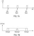
- the power of the WUS beacon may be iteratively reduced by changing a gain setting in the WUR.
- the WUS beacon with normal power may be generated in the network with normal and/or constant power level.
- the WUS beacon with normal power may be received by the UE with different power (e.g., gain) settings in a receiver chain.
- FIGs. 7A and 7B illustrate an example of scheduling the WUS beacons and the UE gain setting during each WUS beacon for range detection, according to certain exemplary embodiments.
- FIG. 9 illustrates an example coverage area configuration in which a UE moves related to a network node using the multi-gain approach, according to various exemplary embodiments.
- the WUS coverage area may be divided into sub-regions or otherwise marked based on different gain settings for each sub-region within the WUS coverage area.
- Each sub-region within the WUS coverage area may have a different gain setting which may then be used by the UE to determine the UE's location within or relative to the WUS coverage area.
- step 1040 the main radio may be activated/turned on to perform legacy paging procedures and the UE may exit the WUS mode.
- the WUR may remain enabled to allow for continued monitoring for a WUS beacon which may be able to be decoded. If the decoding is successful, the procedure continues to step 1050.
- the WUR of the UE may monitor for a WUS beacon sequence with a reduced power level (e.g., gain).
- a reduced power level e.g., gain
- the WUR may be set to monitor for a specified reduced gain setting, which is less than the gain setting used in step 1020.
- the WUR may incrementally, gradually, or randomly reduce the value of the gain setting as compared to the previous iteration or repetition.
- One exemplary approach may be to start with a relatively high gain and reduce this gain over time until a certain limit, which may be a limit close to where the UE may not be able to decode the beacon.
- Another exemplary approach may start with a relatively low gain and may increase the gain over time, which may have an increased risk because the UE may lose a timing ability if the decoding of the WUS is failing for multiple iterations.
- a further approach may be to increase the gain incrementally if a decoding fails.
- the UE may include a counter which may be incremented for each iteration or repetition of step 1050.
- the UE may attempt to decode the WUS beacon. If the decoding is successful and a value of the counter is less than a threshold value X, the procedure continues to step 1070.
- the WUR may proceed to step 1070 and enter the sleep mode or deep sleep mode for the next DRx cycle.
- the value of the threshold X may be a dynamically updated parameter based on, for example, precious measurements, pre-knowledge of the environment or location, and/or may be scalable depending on the required power budget for the UE. If or when the detection and decoding continue to fail and the counter reaches or exceeds the value of the threshold X, the procedure returns to step 640 in which the main radio may be activated/turned on to perform legacy paging procedures and the UE may exit the WUS mode. As mentioned above, the WUR may remain enabled to allow for continued monitoring for a WUS beacon which may be able to be decoded. If a WUS beacon is detected in the future, the UE may re-enter the WUS mode at step 1010.
- Certain exemplary embodiments may advantageously provide that the one or more procedures may provide for using multi gain settings in the WUR mode for the UE to estimate multi-coverage areas and have the capability to determine whether transient areas between the coverage region should be changed.
- some exemplary embodiments may advantageously minimize the repeated switching back and forth between WUS mode and legacy paging.
- the UE may advantageously estimate environment changes, such as mobility and/or the like.
- Some exemplary embodiments may advantageously provide that the one or more procedures may provide for network-provided detection of a coverage area based on WUS beacon modulation/bitrate.
- the size of the transient area between WUS coverage area and the area using legacy paging may advantageously be fully controlled by the network.
- FIG. 11 illustrates an example of WUS beacon sequences with different bitrates, according to some exemplary embodiments.
- FIG. 12 illustrates an example of a scheduling diagram for a WUS beacon combined with a WUS beacon having a lower bitrate, according to certain exemplary embodiments.
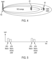
- the UE may decode a first WUS beacon with a lowest bitrate and verify whether the UE is within the WUS coverage area, such as the coverage area shown in FIG. 4 .
- the second WUS beacon with the higher bitrate e.g., shorter ON-OFF duration
- FIG. 13 illustrates an example flow diagram of a method, according to certain exemplary embodiments.
- the method of FIG. 13 may be performed by an entity or device connected to a network, or a group of multiple elements connected to the network in a 3GPP system, such as LTE or 5G-NR.
- the method of FIG. 13 may be performed by a user equipment, user device, or mobile device connected to the network, such as a UE similar to apparatus 1410 illustrated in FIG. 14 .
- the method of FIG. 13 may include, at 1310, monitoring a current cell for a first wake-up signal beacon during a wake-up signal mode, and at 1320, monitoring the current cell for a second wake-up signal beacon during the wake-up signal mode for one or more iterations, upon the first wake-up signal beacon being detected.
- the current cell may be iteratively monitored and during each iteration a gain setting may be incrementally reduced for monitoring for the second wake-up signal beacon.
- the method may further include, at 1330, determining a coverage region of the current cell based on whether the second wake-up signal beacon is detected by the monitoring within a threshold number of iterations.
- the method also includes switching the apparatus into a paging mode using a main radio, when the second wake-up signal beacon is not detected by the monitoring within the threshold number of iterations.
- the method may also include continuing to monitor for further wake-up signal beacons during the paging mode and means for switching from the paging mode to the wake-up signal mode upon detecting at least one further wake-up signal beacon.
- the method may further include determining that the coverage region of the current cell is acceptable based on the second wake-up signal beacon being detected by the monitoring within the threshold number of iterations.
- the coverage region may include a plurality of gain settings, and as the gain setting is incrementally changed to be one or more of the plurality of gain settings, the UE may be configured to determine at least a relative position or a speed of the UE relative to a boundary of the coverage region.
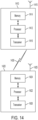
- FIG. 14 illustrates a set of apparatuses 1410 and 1420 according to various exemplary embodiments.
- the apparatus 1410 may be an element in a communications network or associated with such a network, such as a UE, RedCap UE, SL UE, mobile equipment (ME), mobile station, mobile device, stationary device, IoT device, or other device.
- UE 401/901 according to various exemplary embodiments discussed above may be an example of apparatus 1410. It should be noted that one of ordinary skill in the art would understand that apparatus 1410 may include components or features not shown in FIG. 14 .
- apparatuses 1410 and/or 1420 may include or be coupled to processors 1412 and 1422, respectively, for processing information and executing instructions or operations.
- Processors 1412 and 1422 may be any type of general or specific purpose processor.
- processors 1412 and 1422 may include one or more of general-purpose computers, special purpose computers, microprocessors, digital signal processors (DSPs), field-programmable gate arrays (FPGAs), application-specific integrated circuits (ASICs), and processors based on a multi-core processor architecture, as examples. While a single processor 1412 (and 1422) for each of apparatuses 1410 and/or 1420 is shown in FIG. 14 , multiple processors may be utilized according to other example embodiments.
- apparatuses 1410 and/or 1420 may include two or more processors that may form a multiprocessor system (for example, in this case processors 1412 and 1422 may represent a multiprocessor) that may support multiprocessing.
- the multiprocessor system may be tightly coupled or loosely coupled to, for example, form a computer cluster).
- Processors 1412 and 1422 may perform functions associated with the operation of apparatuses 1410 and/or 1420, respectively, including, as some examples, precoding of antenna gain/phase parameters, encoding and decoding of individual bits forming a communication message, formatting of information, and overall control of the apparatuses 1410 and/or 1420, including processes illustrated in FIGs. 4-13 .
- Apparatuses 1410 and/or 1420 may further include or be coupled to memory 1414 and/or 1424 (internal or external), respectively, which may be coupled to processors 1412 and 1422, respectively, for storing information and instructions that may be executed by processors 1412 and 1422.
- Memory 1414 (and memory 1424) may be one or more memories and of any type suitable to the local application environment, and may be implemented using any suitable volatile or nonvolatile data storage technology such as a semiconductor-based memory device, a magnetic memory device and system, an optical memory device and system, fixed memory, and/or removable memory.
- memory 1414 can be comprised of any combination of random access memory (RAM), read only memory (ROM), static storage such as a magnetic or optical disk, hard disk drive (HDD), or any other type of non-transitory machine or computer readable media.
- RAM random access memory
- ROM read only memory
- HDD hard disk drive
- the instructions stored in memory 1414 and memory 1424 may include program instructions or computer program code that, when executed by processors 1412 and 1422, enable the apparatuses 1410 and/or 1420 to perform tasks as described herein.
- apparatuses 1410 and/or 1420 may also include or be coupled to one or more antennas 1415 and 1425 for receiving a downlink signal and for transmitting via an uplink from apparatus 1410 and apparatus 1420, respectively.
- Apparatuses 1410 and/or 1420 may further include transceivers 1416 and 1426, respectively, configured to transmit and receive information.
- the transceiver 1416 and 1426 may also include a radio interface that may correspond to a plurality of radio access technologies including one or more of GSM, LTE, LTE-A, 5G, NR, WLAN, NB-IoT, Bluetooth, BT-LE, NFC, RFID, UWB, or the like.
- the radio interface may include other components, such as filters, converters (for example, digital-to-analog converters or the like), symbol demappers, signal shaping components, an Inverse Fast Fourier Transform (IFFT) module, or the like, to process symbols, such as OFDMA symbols, carried by a downlink or an uplink.
- filters for example, digital-to-analog converters or the like
- symbol demappers for example, digital-to-analog converters or the like
- signal shaping components for example, an Inverse Fast Fourier Transform (IFFT) module, or the like
- IFFT Inverse Fast Fourier Transform
- transceivers 1416 and 1426 may be respectively configured to modulate information on to a carrier waveform for transmission and demodulate received information for further processing by other elements of apparatuses 1410 and/or 1420.
- transceivers 1416 and 1426 may be capable of transmitting and receiving signals or data directly.
- apparatuses 1410 and/or 1420 may include an input and/or output device (I/O device).
- apparatuses 1410 and/or 1420 may further include a user interface, such as a graphical user interface or touchscreen.
- memory 1414 and memory 1424 store software modules that provide functionality when executed by processors 1412 and 1422, respectively.
- the modules may include, for example, an operating system that provides operating system functionality for apparatuses 1410 and/or 1420.
- the memory may also store one or more functional modules, such as an application or program, to provide additional functionality for apparatuses 1410 and/or 1420.
- the components of apparatuses 1410 and/or 1420 may be implemented in hardware, or as any suitable combination of hardware and software.
- apparatus 1410 may optionally be configured to communicate with apparatus 1420 via a wireless or wired communications link 1430 according to any radio access technology, such as NR.
- processors 1412 and 1422, and memory 1414 and 1424 may be included in or may form a part of processing circuitry or control circuitry.
- transceivers 1416 and 1426 may be included in or may form a part of transceiving circuitry.
- the apparatus 1410 may include at least the processor 1412 and at least the memory 1414, as shown in FIG. 14 .
- the memory may store instructions that, when executed by the processor, cause the apparatus 1410 to monitor a current cell for a first wake-up signal beacon during a wake-up signal mode and monitor the current cell for a second wake-up signal beacon during the wake-up signal mode for one or more iterations, upon the first wake-up signal beacon being detected.
- the current cell may be iteratively monitored and during each iteration a gain setting may be incrementally reduced for monitoring for the second wake-up signal beacon.
- the apparatus 1410 may also be caused to determine a coverage region of the current cell based on whether the second wake-up signal beacon is detected by the monitoring within a threshold number of iterations.
- an apparatus may include means for performing a method, a process, or any of the variants discussed herein.
- the means may include one or more processors, memory, controllers, transmitters, receivers, and/or computer program code for causing the performance of the operations.
- Certain exemplary embodiments may be directed to an apparatus 1410 that includes means for monitoring a current cell for a first wake-up signal beacon during a wake-up signal mode and means for monitoring the current cell for a second wake-up signal beacon during the wake-up signal mode for one or more iterations, upon the first wake-up signal beacon being detected.
- the current cell may be iteratively monitored and during each iteration a gain setting may be incrementally reduced for monitoring for the second wake-up signal beacon.
- the apparatus 1410 may also include means for determining a coverage region of the current cell based on whether the second wake-up signal beacon is detected by the monitoring within a threshold number of iterations.
- circuitry may also cover an implementation of merely a hardware circuit or processor or multiple processors, or portion of a hardware circuit or processor, and the accompanying software and/or firmware.
- circuitry may also cover, for example, a baseband integrated circuit in a server, cellular network node or device, or other computing or network device.
Landscapes
- Engineering & Computer Science (AREA)
- Computer Networks & Wireless Communication (AREA)
- Signal Processing (AREA)
- Mobile Radio Communication Systems (AREA)
Applications Claiming Priority (1)
| Application Number | Priority Date | Filing Date | Title |
|---|---|---|---|
| GB2320074.4A GB2636862A (en) | 2023-12-28 | 2023-12-28 | Wake-up signal and wake-up receiver coverage detection |
Publications (1)
| Publication Number | Publication Date |
|---|---|
| EP4580264A1 true EP4580264A1 (de) | 2025-07-02 |
Family
ID=89844055
Family Applications (1)
| Application Number | Title | Priority Date | Filing Date |
|---|---|---|---|
| EP24221453.4A Pending EP4580264A1 (de) | 2023-12-28 | 2024-12-19 | Erkennung der abdeckung eines aufwecksignals und aufweckempfängers |
Country Status (3)
| Country | Link |
|---|---|
| EP (1) | EP4580264A1 (de) |
| CN (1) | CN120239021A (de) |
| GB (1) | GB2636862A (de) |
Citations (2)
| Publication number | Priority date | Publication date | Assignee | Title |
|---|---|---|---|---|
| US20200187120A1 (en) * | 2017-07-07 | 2020-06-11 | Nokia Technologies Oy | Controlling connectivity for dozing of wireless device |
| US20230119150A1 (en) * | 2021-10-14 | 2023-04-20 | Wiliot, LTD. | Techniques for wakeup in a low-power wireless device |
-
2023
- 2023-12-28 GB GB2320074.4A patent/GB2636862A/en active Pending
-
2024
- 2024-12-19 EP EP24221453.4A patent/EP4580264A1/de active Pending
- 2024-12-27 CN CN202411949787.6A patent/CN120239021A/zh active Pending
Patent Citations (2)
| Publication number | Priority date | Publication date | Assignee | Title |
|---|---|---|---|---|
| US20200187120A1 (en) * | 2017-07-07 | 2020-06-11 | Nokia Technologies Oy | Controlling connectivity for dozing of wireless device |
| US20230119150A1 (en) * | 2021-10-14 | 2023-04-20 | Wiliot, LTD. | Techniques for wakeup in a low-power wireless device |
Also Published As
| Publication number | Publication date |
|---|---|
| CN120239021A (zh) | 2025-07-01 |
| GB2636862A (en) | 2025-07-02 |
| GB202320074D0 (en) | 2024-02-14 |
Similar Documents
| Publication | Publication Date | Title |
|---|---|---|
| US11197338B2 (en) | Power saving radio resource management (RRM) measurements in a wireless network | |
| US12604272B2 (en) | Handling of measurement relaxation and other activity skipping | |
| US20230108646A1 (en) | Power efficient paging mechanism with paging early indicator | |
| CN111328461B (zh) | 用于唤醒信号接收机的回退模式 | |
| JP6925438B2 (ja) | Mtc機器の電力消費を抑えるシグナリング指標 | |
| US20240015657A1 (en) | Method, device, and system for wake up burst in wireless networks | |
| RU2638570C1 (ru) | Способы и сетевые узлы в сети беспроводной связи | |
| CN114097300A (zh) | 用于遗漏的唤醒信号的无线装置自主过程 | |
| US20250344187A1 (en) | Paging clustering in low load cell | |
| US20260089637A1 (en) | Wake-up signal scheme for wake-up management | |
| US12369121B2 (en) | Enhancements for warning/alert system notification with wake up signal | |
| US20250294461A1 (en) | Wakeup signal pattern selection for receiver devices | |
| EP3857986B1 (de) | Zustandsübergangsverfahren für energiesparen bei drahtlosen vorrichtungen | |
| EP4422286A1 (de) | Wecksignal-bakenanordnung zur erkennung der reichweite eines wecksignals | |
| US20240340744A1 (en) | Enhanced cell (re)selection for low power wake-up signal mode of operation | |
| EP4580264A1 (de) | Erkennung der abdeckung eines aufwecksignals und aufweckempfängers | |
| WO2024098634A1 (en) | Power saving techniques for communication systems | |
| WO2023200390A1 (en) | Mechanisms for efficient wake-up radio operation | |
| US20260082326A1 (en) | Method and apparatus for receiving synchronization signal by user equipment having a wake-up receiver in a wireless communication system | |
| US12574853B2 (en) | SCell preparation | |
| CN121040147A (zh) | 用于在网络中传输信号的系统和设备及相关方法 | |
| WO2025066884A1 (zh) | 一种通信方法及装置 | |
| CN121569551A (zh) | 操作用户设备、网络节点、用户设备和无线通信系统的方法 |
Legal Events
| Date | Code | Title | Description |
|---|---|---|---|
| PUAI | Public reference made under article 153(3) epc to a published international application that has entered the european phase |
Free format text: ORIGINAL CODE: 0009012 |
|
| STAA | Information on the status of an ep patent application or granted ep patent |
Free format text: STATUS: THE APPLICATION HAS BEEN PUBLISHED |
|
| AK | Designated contracting states |
Kind code of ref document: A1 Designated state(s): AL AT BE BG CH CY CZ DE DK EE ES FI FR GB GR HR HU IE IS IT LI LT LU LV MC ME MK MT NL NO PL PT RO RS SE SI SK SM TR |
|
| STAA | Information on the status of an ep patent application or granted ep patent |
Free format text: STATUS: REQUEST FOR EXAMINATION WAS MADE |
|
| 17P | Request for examination filed |
Effective date: 20260102 |