EP4580260A1 - Verfahren und vorrichtung zur drahtlosen kommunikation - Google Patents
Verfahren und vorrichtung zur drahtlosen kommunikation Download PDFInfo
- Publication number
- EP4580260A1 EP4580260A1 EP22955952.1A EP22955952A EP4580260A1 EP 4580260 A1 EP4580260 A1 EP 4580260A1 EP 22955952 A EP22955952 A EP 22955952A EP 4580260 A1 EP4580260 A1 EP 4580260A1
- Authority
- EP
- European Patent Office
- Prior art keywords
- backscatter
- signal
- terminal
- target receiving
- power
- Prior art date
- Legal status (The legal status is an assumption and is not a legal conclusion. Google has not performed a legal analysis and makes no representation as to the accuracy of the status listed.)
- Pending
Links
Images

Classifications
-
- H—ELECTRICITY
- H04—ELECTRIC COMMUNICATION TECHNIQUE
- H04W—WIRELESS COMMUNICATION NETWORKS
- H04W52/00—Power management, e.g. Transmission Power Control [TPC] or power classes
- H04W52/04—Transmission power control [TPC]
- H04W52/18—TPC being performed according to specific parameters
- H04W52/24—TPC being performed according to specific parameters using SIR [Signal to Interference Ratio] or other wireless path parameters
- H04W52/242—TPC being performed according to specific parameters using SIR [Signal to Interference Ratio] or other wireless path parameters taking into account path loss
-
- H—ELECTRICITY
- H04—ELECTRIC COMMUNICATION TECHNIQUE
- H04B—TRANSMISSION
- H04B17/00—Monitoring; Testing
- H04B17/30—Monitoring; Testing of propagation channels
- H04B17/309—Measuring or estimating channel quality parameters
- H04B17/318—Received signal strength
-
- H—ELECTRICITY
- H04—ELECTRIC COMMUNICATION TECHNIQUE
- H04W—WIRELESS COMMUNICATION NETWORKS
- H04W52/00—Power management, e.g. Transmission Power Control [TPC] or power classes
-
- H—ELECTRICITY
- H04—ELECTRIC COMMUNICATION TECHNIQUE
- H04W—WIRELESS COMMUNICATION NETWORKS
- H04W74/00—Wireless channel access
- H04W74/08—Non-scheduled access, e.g. ALOHA
- H04W74/0833—Random access procedures, e.g. with 4-step access
-
- H—ELECTRICITY
- H04—ELECTRIC COMMUNICATION TECHNIQUE
- H04W—WIRELESS COMMUNICATION NETWORKS
- H04W74/00—Wireless channel access
- H04W74/08—Non-scheduled access, e.g. ALOHA
- H04W74/0833—Random access procedures, e.g. with 4-step access
- H04W74/0836—Random access procedures, e.g. with 4-step access with 2-step access
-
- H—ELECTRICITY
- H04—ELECTRIC COMMUNICATION TECHNIQUE
- H04W—WIRELESS COMMUNICATION NETWORKS
- H04W76/00—Connection management
- H04W76/20—Manipulation of established connections
Definitions
- Embodiments of the present application relate to the field of communications, and particular to, a wireless communication method and a device.
- the present application provides a wireless communication method and a device, where a terminal device determines a target transmission mode used for transmitting a signal based on transmitting power of a backscatter signal, a path loss and a target receiving power of a target receiving device, which is beneficial for balancing power saving of the terminal and reliable transmission of the signal.
- a wireless communication method which includes: determining, by a first terminal based on transmitting power of a backscatter signal, a path loss between the first terminal and a target receiving device and target receiving power of the target receiving device, a target transmission mode of a first signal from multiple transmission modes, where the multiple transmission modes include an active transmission mode and a backscatter mode, and the target receiving device is a receiving device of the first signal.
- a wireless communication method which includes: receiving, by a target receiving device in a target receiving mode based on a backscatter time window, a first signal transmitted by a first terminal.
- a computer-readable storage medium for storing a computer program, where the computer program causes a computer to perform the method according to any of the first aspect to the second aspect or various implementations thereof.
- a computer program product includes computer program instructions, where the computer program instructions enable a computer to perform the method in any of the first aspect to the second aspect various implementations thereof.
- a computer program when executed on a computer, causes the computer to perform the method in any of the first aspect to the second aspect or various implementations thereof.
- the terminal device determines the target transmission mode used for transmitting the signal based on transmitting power of the backscatter signal, the path loss and the target receiving power of the target receiving device, which is beneficial for balancing the power saving of the terminal and reliable transmission of the signal.
- the communication system in the embodiments of the present application may be applied to an unlicensed spectrum, and the unlicensed spectrum may also be considered as a shared spectrum.
- the communication system in the embodiments of the present application may be applied to a licensed spectrum, and the licensed spectrum may be considered as an unshared spectrum.
- the terminal device may be referred to as a user equipment (UE), an access terminal, a user unit, a user station, a mobile station, a mobile platform, a remote station, a remote terminal, a mobile device, a user terminal, a terminal, a wireless communication device, a user agent, a user apparatus, or the like
- the network device may be a device used for communicating with a mobile device.
- the network device may be an access point (AP) in WLAN, a base station (Base Transceiver Station, BTS) in GSM or CDMA, or may also be a base station (NodeB, NB) in WCDMA, or may also be an evolutional base station (Evolutional Node B, eNB or eNodeB) in LTE, a relay station or an access point, an in-vehicle device, a wearable device, a network device (gNB) in an NR network, a network device in a cellular internet of things, a network device in a cellular passive internet of things, a network device in a future evolved public land mobile network (PLMN) network, a network device in an NTN network, or the like.
- AP access point
- BTS Base Transceiver Station
- NodeB NodeB
- NB evolutional base station
- gNB network device
- PLMN future evolved public
- the network device may provide a service for a cell, and the terminal device communicates with the network device through a transmission resource (e.g., a frequency-domain resource, or a spectrum resource) used by the cell.
- the cell may be a cell corresponding to the network device (e.g., a base station), and the cell may belong to a macro base station, or may belong to a base station corresponding to a small cell.
- the small cell here may include a metro cell, a micro cell, a pico cell, a femto cell, or the like. These small cells have characteristics of small coverage range and low transmitting power, which are applicable for providing a data transmission service with high speed.
- the terminal device may be deployed on land including indoor or outdoor, handheld, wearable, or in-vehicle; alternatively, the terminal device may be deployed on water (e.g., on a steamship); alternatively, the terminal device may be deployed in air (e.g., on an airplane, on a balloon, or on a satellite).
- the terminal device may be a mobile phone, a pad, a computer with a wireless transceiver function, a virtual reality (VR) terminal device, an augmented reality (AR) terminal device, a wireless terminal device in industrial control, a wireless terminal device in self-driving, a wireless terminal device in remote medical, a wireless terminal device in smart grid, a wireless terminal device in transportation safety, a wireless terminal device in smart city, a wireless terminal device in smart home, or the like.
- VR virtual reality
- AR augmented reality
- the terminal device may be a wearable device.
- the wearable device may be referred to as a wearable smart device, which is a general term of wearable devices developed by intelligent design and development on daily wear by applying wearable technology, such as glasses, gloves, watches, clothing and shoes.
- the wearable device is a portable device that is worn directly on a body, or integrated into clothes or accessories of users.
- the wearable device not only is a hardware device, but also implements powerful functions through software supporting as well as data interaction or cloud interaction.
- Generalized wearable smart devices includes devices that are fully functional, large in size, and may implement full or partial functions without relying on smart phones, such as a smart watche or smart glasses, as well as devices that only focus on a certain type of application functions and need to be used in conjunction with other devices (e.g., smart phones), such as various smart bracelets and smart jewelry that are used for monitoring physical signs.
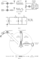
- the communication system 100 may include a network device 110, and the network device 110 may be a device that communicates with a terminal device 120 (or referred to as a communication terminal or a terminal).
- the network device 110 may provide communication coverage for a specific geographical area and may communicate with terminal devices located within the coverage.
- FIG. 1 exemplarily shows a network device and two terminal devices.
- the communication system 100 may include a plurality of network devices, and coverage range of each network device may be provided therein with other number of terminal devices, which is not limited in the embodiments of the present application.
- the communication system 100 may further include a network controller, a mobility management entity, and other network entities, which are not limited in the embodiments of the present application.
- a device with communication functions in the network/system in the embodiments of the present application may be referred to as a communication device.
- the communication devices may include a network device 110 and a terminal device 120 with communication functions.
- the network device 110 and the terminal device 120 may be the specific devices as described above, which will not be repeated here.
- the communication devices may further include other devices in the communication system 100, such as a network controller, a mobility management entity, and other network entities, which are not limited in the embodiments of the present application.
- indicate mentioned in the embodiments of the present application may mean a direct indication, an indirect indication, or an indication of an association relationship.
- a indicating B may mean that A directly indicates B, for example, B may be obtained through A; alternatively, A indicating B may mean that A indirectly indicates B, for example, A indicates C, and B may be obtained through C; alternatively, A indicating B may mean that there is an association relationship between A and B.
- predefined may be achieved by pre-storing corresponding codes, tables or other methods that may be used to indicate related information in devices (e.g., including the terminal device and the network device), and the specific implementation is not limited in the present application.
- predefined may refer to what is defined in a protocol.
- the "protocol” may refer to a standard protocol in the field of communication, for example, it may include an LTE protocol, a NR protocol, or related protocols applied in further communication systems, which will not be limited in the present application.
- the key technologies of the zero power consumption communication include power harvesting, backscatter communication and low power consumption technology.
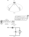
- a typical zero power consumption communication system (e.g., a radio frequency identification (RFID) system) includes a network device (e.g., a reader/writer of the RFID system) and a zero power consumption terminal (e.g., an electronic tag).
- the network device is used to transmit a wireless power supply signal and a downlink communication signal to the zero power consumption terminal, and receive a backscatter signal from the zero power consumption terminal.
- a basic zero power consumption terminal includes a power harvesting module, a backscatter communication module, and a low power consumption calculating module.
- the zero power consumption terminal may further have a memory or a sensor for storing basic information (e.g., an object identification) or sensing data such as ambient temperature and ambient humidity.
- the power harvesting module may harvest power carried by radio waves (radio waves emitted by a network device shown in FIG. 2 ) in space to drive the low power consumption calculating module of the zero power consumption terminal and realize backscatter communication.
- the zero power consumption terminal may receive a control command from the network device and transmit data to the network device based on the control signaling by means of backscatter.
- the transmitted data may be data stored in the zero power consumption terminal itself (e.g., an identifier, or pre-written information such as a production date, a brand, or a manufacturer of a product).
- the zero power consumption terminal may also be loaded with various sensors, so as to report data collected by various sensors based on zero power consumption mechanism.
- a radio frequency power harvesting module harvests electromagnetic wave power in space based on a principle of electromagnetic induction, so as to obtain power required for driving the zero power consumption terminal to work, for example, for driving a low power demodulation and modulation module, a sensor, and memory reading. Therefore, the zero power consumption terminal does not need a traditional battery.
- the zero power consumption terminal may also drive the load circuit by harvesting ambient power (e.g., light power, thermal power, kinetic power, wind power, solar power).
- ambient power e.g., light power, thermal power, kinetic power, wind power, solar power.
- the zero power consumption terminal receives a carrier signal transmitted by the network device, modulates the carrier signal, loads information to be transmitted and radiates the modulated signal by an antenna.
- This information transmission process is referred to as backscatter communication.
- Backscatter and load modulation functions are inseparable.
- Load modulation is a method often used by electronic tags to transmit data to the reader/writer. Load modulation adjusts and controls circuit parameters of an oscillation loop of the zero power consumption terminal according to rhythm of data stream, so that parameters such as impedance of the zero power consumption terminal change accordingly, thereby completing the modulation process.
- the load modulation technology mainly includes two manners: resistive load modulation and capacitive load modulation.
- a load is connected in parallel with a resistor, and the resistor is switched on or off based on the control of a binary data stream, as shown in FIG. 5 .
- the on and off of the resistor will cause a circuit voltage to change, and thus an amplitude shift keying (ASK) modulation is achieved, that is, modulation and transmission of the signal is achieved by adjusting an amplitude of a backscatter signal of the zero power consumption terminal.
- ASK amplitude shift keying
- resonant frequencies of a circuit may be changed by switching capacitor on and off, and thus a frequency shift keying (FSK) modulation is achieved, that is, modulation and transmission of the signal is achieved by an operating frequency of a backscatter signal of the zero power consumption terminal.
- FSK frequency shift keying
- the zero power consumption terminal performs information modulation on an incoming signal by means of load modulation, thereby implementing a backscatter communication process. Therefore, the zero power consumption terminal has significant advantages as that:
- Data transmitted by a zero power consumption terminal may use different forms of codes to represent binary "1" and "0".
- a radio frequency identification system usually uses one of the following encoding modes: reverse non-return-to-zero (NRZ) encoding, Manchester encoding, unipolar return-to-zero encoding, differential bi-phase (DBP) encoding, differential encoding, pulse interval encoding (PIE), bi-phase space encoding (FM0), Miller encoding, differential dynamic encoding, or the like.
- NRZ reverse non-return-to-zero
- DBP differential bi-phase
- PIE pulse interval encoding
- FM0 bi-phase space encoding
- Miller encoding differential dynamic encoding
- the zero power consumption terminal may be divided into following types.
- the zero power consumption terminal (e.g., an electronic tag in an RFID system) does not need a built-in battery.
- a network device e.g., a reader/writer of the RFID system
- the zero power consumption terminal is within a near-field formed by antenna radiation of the network device. Therefore, an antenna of the zero power consumption terminal generates an induced current through electromagnetic induction, and the induced current drives a low power consumption chip circuit of the zero power consumption terminal, so as to implement demodulation of a signal on a forward link, modulation of a signal on a backward link (or referred to as a backscatter link) and other operations.
- the zero power consumption terminal transmits a signal by means of backscatter.
- the semi-passive zero power consumption terminal does not require a built-in battery to drive either in a forward link or in a backward link. Although the power stored in the capacitor is used in operation, the power comes from the radio power harvested by the power harvesting module. Therefore, the semi-passive zero power consumption terminal is also a true zero power consumption terminal.
- the power supply signal may be a continuous wave or a discontinuous wave (i.e., allowing for a certain duration of interruption).
- the power supply signal may also be implemented by adding a new signal, for example, adding a new signal dedicated to supply power.
- the carrier may be a base station, a smart phone, a smart gateway, or the like.
- the trigger signal may be a continuous wave or a discontinuous wave (i.e., allowing for a certain duration of interruption).
- the trigger signal may also be implemented by adding a new signal, for example, adding a new signal dedicated to triggering or scheduling.
- the carrier signal is used by the zero power consumption terminal to generate a backscatter signal.
- the zero power consumption terminal may modulate a received carrier signal according to information that need to be transmitted to form a backscatter signal.
- the carrier may be a base station, a smart phone, a smart gateway, or the like.
- a radio wave used for the carrier signal may be a sine wave, a square wave, a triangle wave, a pulse, a rectangular wave, or the like.
- the carrier signal may be a continuous wave or a discontinuous wave (i.e., allowing for a certain duration of interruption).
- the carrier signal may be an existing signal in the 3GPP standard.
- an SRS for example, an SRS, a PUSCH, a PRACH, a PUCCH, a PDCCH, a PDSCH, a PBCH, a WIFI signal or a Bluetooth signal, or the like.
- the carrier signal may also be implemented by adding a new signal, for example, adding a new carrier signal dedicated to generating a backscatter signal.
- a first-type terminal and a second-type terminal there are multiple terminals that support both active transmission communication and backscatter communication (e.g., a first-type terminal and a second-type terminal exist) in the communication system, and capabilities of these terminals are different.
- the second-type terminal uses LNA, and the second-type terminal does not use LNA.
- capabilities of LNAs of the first-type terminal and the second-type terminal are different, for example, a power amplification coefficient of the LNA of the first-type terminal is smaller than that of the second-type terminal.
- backscatter losses of the first-type terminal and the second-type terminal are different when performing backscatter, for example, a backscatter loss of the second-type terminal is 5 dB, and a backscatter loss of the first-type terminal is 8 dB. Therefore, the following situations may occur.
- FIG. 7 is a schematic diagram of a wireless communication method 200 according to the embodiments of the present application. As shown in FIG. 7 , the method 200 includes at least part of the following contents.
- a first terminal determines a target transmission mode of a first signal from multiple transmission modes based on transmitting power of a backscatter signal, a path loss between the first terminal and a target receiving device and target receiving power of the target receiving device, where the multiple transmission modes include an active transmission mode and a backscatter mode, and the target receiving device is a receiving device of the first signal.
- S210 may also be replaced by: determining, by the first terminal based on the transmitting power of the backscatter signal, the path loss between the first terminal and the target receiving device and the target receiving power of the target receiving device, whether to transmit the first signal in the backscatter mode.
- the target receiving device is a network device. That is, the first signal may be an uplink signal.
- the first signal may be any uplink signal, or may be replaced by an uplink channel, uplink information, uplink data, or the like.
- the first signal may be an uplink signal in a random access process, such as a preamble signal, or a message 3 (Msg3), or a message A (MsgA).
- a preamble signal such as a preamble signal, or a message 3 (Msg3), or a message A (MsgA).
- Msg3 message 3
- MsgA message A
- the first signal may be an uplink signal in a low latency transmission scenario.
- the target receiving device is a second terminal. That is, the first signal may be a sidelink signal.
- the first signal may be any sidelink signal, or may be replaced by a sidelink channel, sidelink information, sidelink data, or the like.
- the first signal may be a physical sidelink shared channel (PSSCH), a physical sidelink control channel (PSCCH), or sidelink control information (SCI).
- PSSCH physical sidelink shared channel
- PSCCH physical sidelink control channel
- SCI sidelink control information
- the first terminal supports the active transmission mode and the backscatter mode, in other words, the first terminal supports active transmission communication and backscatter communication. That is, the first terminal supports a dual-mode transmission mode, in other words, a dual-mode communication mode.
- the first terminal may be an active terminal, a semi-passive terminal, or a passive terminal.
- the first terminal may have a power storage capability, or may not have the power storage capability.
- the first terminal may be a first type zero power consumption terminal, where the first type zero power consumption terminal does not have a power storage unit and a power amplifier device.
- the first terminal may be a second type zero power consumption terminal, where the second type zero power consumption terminal has a power storage unit but does not have a power amplifier device.
- the first terminal may be a third type zero power consumption terminal, where the third type zero power consumption terminal has a power amplifier device but does not have a power storage unit.
- UE1 does not provided with power storage capability, and mainly performs power harvesting on a radio frequency signal, and UE1 does not provided with the LNA.
- the active transmitting signal and the backscatter signal may share the target receiving power, or the active transmitting signal and the backscatter signal may correspond to different target receiving power respectively.
- the path loss may be measured by the target receiving device and indicated to the first terminal.
- the target receiving device is the network device, and the network device may indicate the path loss to the first terminal through any downlink signaling.
- the target receiving device is the second terminal, and the second terminal may indicate the path loss to the first terminal through any sidelink signaling.
- the path loss is measured by the first terminal.
- the path loss in a case where the path loss is measured by the first terminal, the path loss may be measured by the auxiliary receiver, or may be measured by the main receiver (for example, the auxiliary receiver is shared, or the main receiver and the auxiliary receiver are the same receiver).
- the path loss of the backscatter communication may be directly calculated based on the measurement result of the second signal.
- the path loss of the backscatter communication may be obtained by processing the measurement result of the second signal.
- the path loss of the backscatter communication is calculated by processing the measurement result through an adjustment factor, an adjustment amount, etc.
- the target receiving device is a network device
- the second signal may be a downlink reference signal, for example, a synchronization signal block (SSB), a channel state information reference signal (CSI-RS).
- SSB synchronization signal block
- CSI-RS channel state information reference signal
- the target receiving device is a second terminal, and the second signal may be a sidelink reference signal, for example, a sidelink position reference signal (Sidelink Positioning Reference Signals, SL-PRS).
- SL-PRS Sidelink Positioning Reference Signals
- the path loss may be characterized by a measurement result of a signal, for example, the measurement result may include but is not limited to: reference signal receiving power (RSRP), reference signal receiving quality (RSRQ), signal to interference plus noise ratio (SINR), and received signal strength indication (RSSI).
- RSRP reference signal receiving power
- RSRQ reference signal receiving quality
- SINR signal to interference plus noise ratio
- RSSI received signal strength indication
- a unit of the path loss may be dBm.
- the target receiving device is the network device
- the first terminal may measure an activated uplink (UL) band width part (BWP) b on carrier frequency f based on the downlink reference signal associated with backscatter communication in the activate downlink BWP of the serving cell c to obtain the path loss PL b,f,c .
- UL uplink
- BWP band width part
- the target receiving device is the second terminal, and the first terminal may measure the activated sidelink (SL) BWP b on the carrier frequency f based on a sidelink reference signal associated with backscatter communication in the activated sidelink BWP to obtain the path loss PL b,f .
- SL sidelink
- the transmitting power of the backscatter signal may refer to power of the backscatter signal finally transmitted in a case where the first terminal communicates in a backscatter mode.
- the transmitting power of the backscatter signal may be less than, equal to, or greater than incident power of a carrier signal.
- backscatter may be performed directly based on the carrier signal. Since there is a certain loss in the backscatter communication, the transmitting power of the backscatter signal is usually less than the incident power of the carrier signal.
- the first terminal may further perform amplification on the backscatter signal.
- the transmitting power of the backscatter signal may be greater than or equal to the incident power of the carrier signal.
- the transmitting power of the backscatter signal is related to factors such as the power of the carrier signal, a gain of the first terminal, and the loss of the backscatter communication.
- Manner 1 the transmitting power of the backscatter signal is determined by power of a carrier signal and a first gain.
- the first gain is a gain of the transmitting power of the backscatter signal relative to the power of the carrier signal.
- a sum of the power of the carrier signal and the first gain may be used as the transmitting power of the backscatter signal.
- the carrier signal may be a dedicated carrier signal, or other signal may be used as the carrier signal, such as using a radio signal in the environment as the carrier signal, or using a signal carrying scheduling information of the first signal as the carrier signal.
- the dedicated carrier signal may be provided by the network device, or provided by the target receiving device, or provided by a third-party device.
- the first gain includes at least one of: a loss of the backscatter communication performed by the first terminal UE Backscatter,loss , an antenna gain of the first terminal UE Gain,antenma , a low noise amplifier (LNA) gain of the first terminal UE Gain,LNA , a power storage related gain of the first terminal UE Gain,Power , or other gains of the first terminal UE Gain,other .
- LNA low noise amplifier
- the loss of the backscatter communication performed by the first terminal UE Backscatter,loss includes, for example, but is not limited to, a loss of the backscatter communication itself, optionally, may further include a loss caused by other circuit hardware when performing the backscatter communication.
- UE Gain,Power may include a power gain obtained by the first terminal through a battery, a power storage, other environmental power harvesting manners, or the like.
- UE Gain,other may refer to gains other than those described above.
- the LNA gain of the first terminal may be understood as a power amplification gain of the first terminal, that is, a gain acquired by the amplification of the backscatter signal performed by the first terminal.
- the gain may be brought by the LNA, or brought by a PA, or brought by a device with the power amplification function such as a transistor or a tunnel diode, which is not limited in the present application.
- P B ack scatter denotes the transmitting power of the backscatter signal
- P Carrier denotes the power of the carrier signal
- UE Gain 1 denotes the first gain
- Manner 2 the transmitting power of the backscatter signal is determined by power of a carrier signal, a loss of backscatter communication performed by the first terminal, and a second gain.
- the loss of backscatter communication performed by the first terminal may include, but is not limited to, the loss of the backscatter communication itself, optionally, may further include a loss caused by other circuit hardware when performing backscatter communication.
- the second gain is a gain of the backscatter communication performed by the first terminal.
- the second gain includes at least one of: an antenna gain of the first terminal UE Gain, antenma , an LNA gain of the first terminal UE Gain,LNA , a power storage related gain of the first terminal UE Gain ,Power , or other gains of the first terminal UE Gain, other .
- the transmitting power of the backscatter signal meets the following formula (4):
- P B ack scatter P Carrier ⁇ UE B ack scatter , loss + UE Gain 2
- P Backscatter denotes the transmitting power of the backscatter signal
- P Carrier denotes the power of the carrier signal
- UE Gain 2 denotes the second gain
- UE Backscatter,loss denotes the loss of the backscatter communication performed by the first terminal.
- the power of the carrier signal may be power of the carrier signal at a first time, and the first time is a transmitting time of the first signal.
- the transmitting power of the backscatter signal may be understood as the transmitting power of the backscatter signal at the first time.
- the power of the carrier signal may be power of the carrier signal at a second time, or power of the carrier signal at any time in a time period from the second time to the first time, or average power of the carrier signal in the time period.
- the second time may be a time when the first terminal determines that the first signal needs to be transmitted.
- the second time may be a time when the first terminal receives scheduling information of the first signal.
- the second time may be a reference time indicated by scheduling signaling.
- the second time may be a time when the first terminal determines to initiate the autonomous communication.
- the second time may be a start time of a period.
- the first terminal receives the scheduling information at time t1, the power of the carrier signal may be power of the carrier signal at time t1, accordingly, the transmitting power of the backscatter signal may be considered to be transmitting power of the backscatter signal at time t1.
- the first terminal transmits the first signal at time t2
- the power of the carrier signal may be power of the carrier signal at time t2
- the transmitting power of the backscatter signal may be considered to be transmitting power of the backscatter signal at time t2.
- the first time is predefined.
- the first time may be a fixed time agreed upon in the protocol.
- the first time is configured by a target receiving device or a network device.
- the network device or the target receiving device may indicate the first time through scheduling information of the first signal, or may indicate it through other information. That is, the scheduling information of the first signal and the first time may be transmitted through the same signaling, or may be transmitted through different signaling.
- the network device or the target receiving device may configure the first terminal to periodically transmit the first signal.
- the network device or the target receiving device may configure a transmitting period of the first signal and a transmitting position of the first signal in the transmitting period.
- the first time is determined by the first terminal.
- the first signal is a transmission autonomously initiated by the first terminal, and the transmitting time of the first signal may be determined by the first terminal.
- the first time may be selected by the first terminal from multiple candidate times.
- the multiple candidate times may be predefined or indicated in advance by the network device or the target receiving device.
- the first terminal may consider a power storage gain from the second time to the first time, such as, a gain obtained through power harvesting in the time period from the second time to the first time.
- the power storage gain from the second time to the first time may be considered as a part of the first gain or the second gain mentioned-above, for example, it is belong to the power storage related gain of the first terminal.
- the power storage gain from the second time to the first time may also be considered as an additional gain in addition to the first gain or the second gain.
- the specific division manners are not limited in the present application.
- the first gain in formula (1) may be considered as the first gain or an intrinsic gain at the second time
- the second gain in formula (3) may be considered as a second gain or an intrinsic gain at the second time
- UE Gain 1 denotes the first gain at the second time
- P ⁇ t is the power storage gain from the second time to the first time.
- the transmitting power of the backscatter signal meets the following formula (7):
- P B ack scatter P C arrier ′ + UE Gain 1 ′
- P Backscatter denotes the transmitting power of the backscatter signal
- P C arrier ′ denotes the power of the carrier signal at the first time
- UE G ain 1 ′ denotes the first gain at the first time.
- Manner 4 the transmitting power of the backscatter signal is determined based on the power of the carrier signal at the first time, the first gain, and the power storage gain from the second time to the first time.
- the transmitting power of the backscatter signal meets the following formula (8):
- P B ack scatter P C arrier ′ + UE Gain 1 + P ⁇ t
- P Backscatter denotes the transmitting power of the backscatter signal
- P C arrier ′ denotes the power of the carrier signal at the first time
- UE Gain 1 denotes the first gain
- P ⁇ t is the power storage gain from the second time to the first time.
- Manner 5 the transmitting power of the backscatter signal is determined based on the power of the carrier signal at the first time, the loss of the backscatter communication and the second gain at the first time.
- the transmitting power of the backscatter signal meets the following formula (9):
- P B ack scatter P C arrier , ′ ⁇ UE B ack scatter , loss + UE G ain 2 ′
- P Backscatter denotes the transmitting power of the backscatter signal
- P C arrier ′ denotes the power of the carrier signal at the first time
- UE G ain 2 ′ denotes the second gain at the first time.
- Manner 6 the transmitting power of the backscatter signal is determined based on the power of the carrier signal at the first time, the loss of the backscatter communication, the second gain and the power storage gain from the second time to the first time.
- the transmitting power of the backscatter signal meets the following formula (10):
- P B ack scatter P C arrier ′ ⁇ UE B ack scatter , loss + UE G ain 2 + P ⁇ t
- P Backscatter denotes the transmitting power of the backscatter signal
- P C arrier ′ denotes the power of the carrier signal at the first time
- UE Gain 2 denotes the second gain
- P ⁇ t is the power storage gain from the second time to the first time.
- the method 200 further includes: performing, by the first terminal, harvest power starting at the second time.
- the first terminal does not store power before the second time, and stores power starting from the second time.
- power is not performed until scheduling information of the first signal is received, and the first terminal performs power storage starting from the scheduling information of the first signal being received.
- the method 200 further includes: switching, by the first terminal, a power harvesting mode from a first mode to a second mode at the second time, where power harvesting efficiency of the second mode is higher than power harvesting efficiency of the first mode.
- sources of power harvesting in the second mode is more than sources of power harvesting in the first mode.
- the first terminal in the first mode, mainly performs power harvesting in a radio frequency signal, and in the second mode, the first terminal may perform power harvesting on any environmental signal.
- S210 includes:
- the transmitting power of the backscatter signal passing through the path loss between the first terminal and the target receiving device, reaches the target receiving device, and the receiving power of the target receiving device meets the requirement of a target receiving power of the target receiving device, the transmitting power of the backscatter signal is considered to meet the first condition; otherwise, the transmitting power of the backscatter signal is considered to not meet the first condition.
- the first condition includes:
- the target transmission mode of the first signal is the backscatter mode: P B ack scatter > P B ack scatter , t arg et + PL b P B ack scatter ⁇ P B ack scatter , t arg et + PL b
- the target transmission mode of the first signal is the active transmission mode: P B ack scatter ⁇ P B ack scatter , t arg et + PL b P B ack scatter ⁇ P B ack scatter , t arg et + PL b
- P Backscatter,f,c is determined based on any one of the above formulas (2), (4), (7) to (10).
- the target receiving device is a network device
- P B ack scatter,t arg et in the above formula may be the path loss P B ack scatter,t arg et,f,c mentioned above.
- the target receiving device is a second terminal
- P B ack scatter,t arg et in the above formula may be the path loss P B ack scatter,t arg et,f mentioned above.
- the target receiving device is the network device, PL b in the above formula may be the path loss PL b,f,c mentioned above.
- the target receiving device is the second terminal, PL b in the above formula may be the path loss PL b,f mentioned above.
- the manner for determining the target transmission mode of the first signal is described.
- the first terminal determines to transmit a first signal, for example, based on scheduling (for example, scheduling of the network device), or autonomously decides to transmit the first signal. Furthermore, the first terminal determines the target transmission mode for transmitting the first signal based on the transmitting power of the backscatter signal, the path loss, and the target receiving power of the network device.
- the first signal is transmitted in a backscatter mode
- P B ack scatter,f,c > P B ack scatter,t arg et,f,c +PL b,f,c
- the first signal is transmitted in the active transmission mode
- the first terminal determines to transmit the first signal when scheduling information is received. After receiving the scheduling information, the first terminal may perform power harvesting, and further determine the target transmission method for transmitting the first signal based on the transmitting power of the backscatter signal (the transmitting power here is determined based on the power of the carrier signal at the time of transmitting the first signal), the path loss and the target receiving power of the network device.
- the transmitting power here is determined based on the power of the carrier signal at the time of transmitting the first signal
- the path loss the target receiving power of the network device.
- the first signal is transmitted in the backscatter mode
- P Backscatter,f,c ⁇ P B ack scatter,t arg et,f,c + PL b,f,c
- the first signal is transmitted in the active transmission mode
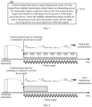
- S210 includes: determining, based on target transmitting power of the backscatter signal, the path loss between the first terminal and the target receiving device and the target receiving power of the target receiving device, the target transmission mode of the first signal from the multiple transmission modes within a backscatter time window.
- the first terminal determines the target transmission mode of the first signal in the aforementioned manners within the backscatter time window.
- the transmitting power of the backscatter signal meets a first condition at a third time within the backscatter time window, transmitting the first signal in the backscatter mode.
- the transmitting power of the backscatter signal in response to that the transmitting power of the backscatter signal does not meets the first condition at the third time within the backscatter time window and the transmitting power of the backscatter signal meets the first condition at a fourth time within the backscatter time window, transmitting the first signal in the backscatter mode after the fourth time, where the fourth time is later than the third time.
- the first terminal performs power harvesting starting from the third time, that is, does not perform power harvesting before the third time, and power harvesting starts from the third time.
- the first terminal switches the power harvesting mode from a first mode to a second mode starting from the third time, where the power harvesting efficiency of the second mode is higher than the power harvesting efficiency of the first mode.
- sources of the power in the second mode are more than sources of the power in the first mode.
- the first terminal in the first mode, the first terminal mainly performs power harvesting on a radio frequency signal, and in the second mode, the first terminal may perform power harvesting on any environmental signal.
- the power harvesting mode of the first terminal remains unchanged from the third time to the fourth time.
- the power accumulated by the first terminal before the third time is insufficient to complete backscatter communication, and the power accumulated by the first terminal at the fourth time is sufficient to complete the backscatter communication. Therefore, the first terminal may transmit the first signal in the backscatter mode after the fourth time.
- the first signal in response to that the transmitting power of the backscatter signal does not meet the first condition until an ending position of the backscatter time window, the first signal is transmitted in the active transmission mode after the end of the backscatter time window.
- the third time may correspond to the first time, or may also correspond to the second time.
- the first terminal may transmit a signal in the backscatter mode within the backscatter time window (that is, time domain resources used for transmitting the signal do not exceed the backscatter time window), alternatively, the first terminal may start to transmit the signal in the backscatter mode within the backscatter time window.
- the time domain resources used for transmitting the signal may exceed the ending position of the backscatter time window, or may not exceed the ending position of the backscatter time window, which is determined by transmission duration of the signal.
- the backscatter time window may be a periodic time window, or may be a non-periodic time window, for example, a starting position and/or a time duration of the backscatter time window are different in different time periods.
- a unit of a period of the backscatter time window may be symbol, slot, subframe, frame, or the like, or may also be millisecond, second, minute, hour, or the like.
- the period of the backscatter time window may be configured by a network device, or may be configured by a target receiving device, or may be predefined.
- the period of the backscatter time window may be configured by semi-static signaling or dynamic signaling.
- the period of the backscatter time window may be configured before scheduling the first signal, or indicated when transmitting scheduling information of the first signal.
- the network device or the target receiving device may directly indicate a specific duration of the period, or indicate index information corresponding to the period, for example, indicates an index of a target period in multiple periods, where the multiple periods may be predefined or preconfigured (i.e., configured in advance).
- a position of the backscatter time window is fixed.
- the backscatter time window is periodic, and in each period the backscatter time window is at the same position.
- each period may include one backscatter time window, or include multiple backscatter time windows.
- the position of the backscatter time window is variable.
- the starting position of the backscatter time window is variable.
- the starting position of the backscatter time window is indicated by the network device or the target receiving device, or may also be referenced to a reference time domain position, which will be described in the following embodiments.
- the manner for determining the backscatter time window is not limited in the present application.
- the backscatter time window is determined according to predefined information and/or configuration information (e.g., from the network device or the target receiving device).
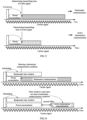
- Embodiment 1 The ending position of the backscatter time window is configured by a target receiving device or a network device.
- the starting position of the backscatter time window may be predefined, or may be determined according to a preset rule.
- the first terminal may acquire the starting position of the backscatter time window without performing signaling interaction with the target receiving device.
- the starting position of the backscatter time window is referenced to a first time domain position.
- the starting position of the backscatter time window is the first time domain position; or for another example, the starting position of the backscatter time window is a second time domain position, where the second time domain position is offset by a first offset relative to the first time domain position.
- the unit of the first offset is not limited in the embodiments of the present application, for example, it may be symbol, slot, subframe, frame, millisecond, second, minute.
- the first offset may be the same, or may be different.
- the first offset is configured by a target receiving device of the first signal.
- the target receiving device is a second terminal, and the second terminal may configure the first offset for the first terminal.
- the first offset may be configured by any sidelink signaling, such as, sidelink RRC signaling or SCI.
- the target receiving device is a network device, and the network device may configure the first offset for the first terminal.
- the first offset may be configured by any downlink signaling, such as RRC signaling, a MAC CE, DCI.
- the first offset may be indicated in advance by a target receiving device of the first signal, or may be indicated by the target receiving device when scheduling the first signal.
- the target receiving device of the first signal may directly indicate a specific offset, or may also indicate an index corresponding to the first offset.
- the target receiving device of the first signal may directly indicate a specific offset, or may also indicate an index corresponding to the first offset.
- multiple offsets are preconfigured, each offset corresponds to an index, and the target receiving device may indicate a specific offset by an index.
- the first offset is configured by a network device.
- the target receiving device is the second terminal
- the network device may configure the first offset for the first terminal.
- the network device may also configure the first offset for the second terminal, or the first terminal may also indicate the first offset to the second terminal.
- the target receiving device is the network device, and the network device may configure the first offset for the first terminal.
- the first offset may be configured by any downlink signaling, such as RRC signaling, a MAC CE, DCI.
- the first offset may be indicated in advance, or may be indicated by the network device when scheduling the first signal.
- the network device may directly indicate a specific offset, or may also indicate an index corresponding to the first offset.
- the network device may directly indicate a specific offset, or may also indicate an index corresponding to the first offset.
- multiple offsets are preconfigured, each offset corresponds to an index, and the network device may indicate a specific offset by an index.
- the first time domain position is a time domain position at which the first terminal receives scheduling information of the first signal.
- the first time domain position may be a moment where the first terminal receives the scheduling information of the first signal, or a time unit occupied by receiving the scheduling information, such as a symbol, a slot, a subframe, a frame.
- the first time domain position is a time domain position indicated by the target receiving device or the network device.
- the first time domain position may be indicated by the target receiving device or the network device through the scheduling information, or, may also be indicated by other information. That is, the target receiving device or the network device may indicate the scheduling information and the first time domain position through the same signaling or different signaling.
- Embodiment 2 a time duration of the backscatter time window is configured by a target receiving device or a network device.
- a starting position of the backscatter time window may be predefined, or determined according to a preset rule.
- the specific determination manners refer to the specific implementations of Embodiment 1, which will not be repeated here for the sake of brevity.
- Example 3 the starting position and the ending position of the backscatter time window are configured.
- the starting position and ending position of the backscatter time window may be configured by a target receiving device.
- the target receiving device is a network device
- the network device may configure the starting position and the ending position of the backscatter time window for the first terminal.
- the target receiving device is a second terminal
- the second terminal may configure the starting position and the ending position of the backscatter time window for the first terminal.
- the starting position and the ending position of the backscatter time window may be configured by a network device.
- the target receiving device is the network device, and the network device may configure the starting position and the ending position of the backscatter time window for the first terminal.
- the target receiving device is the second terminal
- the network device may configure the starting position and the ending position of the backscatter time window for the first terminal.
- the network device may also configure the starting position and the ending position of the backscatter time window for the second terminal, or the first terminal may also indicate the starting position and the ending position of the backscatter time window to the second terminal.
- Embodiment 4 the starting position and the time duration of the backscatter time window are configured.
- the starting position and the time duration of the backscatter time window may be configurable by a target receiving device.
- the target receiving device is a network device
- the network device may configure the starting position and the time duration of the backscatter time window for the first terminal.
- the starting position and the time duration of the backscatter time window may be configured by a network device.
- the target receiving device is the network device, and the network device may configure the starting position and the time duration of the backscatter time window for the first terminal.
- the target receiving device is the second terminal
- the network device may configure the starting position and the time duration of the backscatter time window for the first terminal.
- the network device may also configure the starting position and time duration of the backscatter time window for the second terminal, or the first terminal may also indicate the starting position and the time duration of the backscatter time window to the second terminal.
- Embodiment 5 the ending position and the time duration of the backscatter time window are configured.
- the ending position and time duration of the backscatter time window may be configured by the target receiving device.
- the target receiving device is a network device
- the network device may configure the ending position and the time duration of the backscatter time window for the first terminal.
- the target receiving device is a second terminal
- the second terminal may configure the ending position and the time duration of the backscatter time window for the first terminal.
- the ending position and the time duration of the backscatter time window may be configured by a network device.
- the target receiving device is the network device, and the network device may configure the ending position and the time duration of the backscatter time window for the first terminal.
- the target receiving device is the second terminal
- the network device may configure the ending position and the time duration of the backscatter time window for the first terminal.
- the network device may also configure the ending position and the time duration of the backscatter time window for the second terminal, or the first terminal may also indicate the ending position and the time duration of the backscatter time window to the second terminal.
- a starting position of an active transmission mode may be the ending position of the backscatter time window, or may be a position of a second offset after the ending position.
- the second offset is predefined.
- the second offset is configured by the target receiving device or the network device.
- the configuration manner of the second offset refers to the configuration manner of the first offset mentioned above, which will not be repeated here for the sake of brevity.
- the first terminal receives scheduling information to determine to transmit the first signal in the backscatter time window, the first terminal may perform power harvesting after receiving the scheduling information, and further determine the target transmission mode used for transmitting the first signal according to transmitting power of a backscatter signal (here, the transmitting power may be determined by any of the aforementioned methods), a path loss and target receiving power of the target receiving device.
- the transmitting power may be determined by any of the aforementioned methods
- the first signal is transmitted in a backscatter mode, or, in a case where P Backscatter ⁇ P Backscatter,t arg et +PL b , the first terminal perform power harvesting continuously, if the transmitting power of the backscatter signal does not meet the above formulas until the ending position of the backscatter time window, then the first signal is transmitted in an active transmission mode after the ending position of the backscatter time window, for example, the first signal is transmitted in the active transmission mode starting from the second offset after the ending position.
- the first terminal may determine the target transmission mode used for transmitting the signal based on the transmitting power of the backscatter signal, the path loss and the target receiving power of the target receiving device. For example, in a case were the transmitting power of the backscatter signal meets a requirement of the target receiving power of the target receiving device, the backscatter mode is used to transmit the signal, which is beneficial to reduce power consumption of the terminal. Alternatively, in a case where the transmitting power of the backscatter signal does not meet the requirement of the target receiving power of the target receiving device, the active transmission mode is used to transmit the signal, which is beneficial to ensure reliable transmission of the signal.
- the wireless communication method according to the embodiments of the present application is described in detail above from the perspective of the first terminal in conjunction with FIGS. 7 to 10 .
- a wireless communication method according to another embodiment of the present application will be described in detail below from the perspective of the target receiving device in conjunction with FIG. 11 . It should be understood that, the descriptions on a side of the target receiving device corresponds to the descriptions on side of the first terminal, and similar descriptions may be referred to above, which will not be repeated here for the sake of brevity.
- FIG. 11 is a schematic flowchart of the wireless communication method 300 according to another embodiment of the present application.
- the method 300 includes the following contents: S310, receiving, by a target receiving device in a target receiving mode based on a backscatter time window, a first signal transmitted by a first terminal.
- the target receiving device is a network device; or the target receiving device is a second terminal.
- the method 300 further includes: transmitting, by the target receiving device, first indication information to the first terminal, where the first indication information is used to determine a time domain position of the backscatter time window.
- the target receiving device is the network device
- the first indication information may be carried by any downlink signaling, such as, radio resource control (RRC) signaling, a media access control control element (MAC CE), downlink control information (DCI).
- RRC radio resource control
- MAC CE media access control control element
- DCI downlink control information
- the first indication information is used to indicate at least one of: an ending position of the backscatter time window, a time duration of the backscatter time window, or a starting position of the backscatter time window.
- the first indication information may indicate the starting position and the ending position of the backscatter time window.
- the first indication information may indicate the starting position and the time duration of the backscatter time window.
- the first indication information may indicate the ending position and the time duration of the backscatter time window.
- the first indication information may also only indicate the ending position or the time duration of the backscatter time window.
- the starting position of the backscatter time window may be predefined or determined according to a preset rule. The specific determination manners are referred to the related descriptions of method 200, which will not be repeated here for the sake of brevity.
- the target receiving device is the second terminal
- the method 300 further includes: receiving, by the target receiving device, second indication information transmitted by a network device, where the second indication information is used to determine a time domain position of the backscatter time window.
- the time domain position of the backscatter time window may be determined by the network device.
- the second indication information is configured to indicate at least one of: an ending position of the backscatter time window, a time duration of the backscatter time window, or a starting position of the backscatter time window.
- the second indication information may indicate the starting position and the ending position of the backscatter time window.
- the second indication information may indicate the starting position and the time duration of the backscatter time window.
- the second indication information may indicate the ending position and time duration of the backscatter time window.
- the second indication information may also only indicate the ending position or the time duration of the backscatter time window.
- the starting position of the backscatter time window may be predefined or determined according to a preset rule. The specific determination manners are referred to the related descriptions of method 200, which will not be repeated here for the sake of brevity.
- the starting position of the backscatter time window is referenced to a first time domain position.
- the starting position of the backscatter time window is the first time domain position; or the starting position of the backscatter time window is a second time domain position, where the second time domain position is offset by a first offset relative to the first time domain position.
- the method 300 further includes: transmitting, by the target receiving device, third indication information to the first terminal, where the third indication information is used to indicate the first time domain position.
- the target receiving device may configure the first time domain position for the first terminal.
- the target receiving device is the network device, and the network device may configure the first time domain position for the first terminal.
- the target receiving device is the second terminal, and the second terminal may configure the first time domain position for the first terminal.
- the target receiving device is the second terminal, and the method 300 further includes: receiving, by the target receiving device, fourth indication information transmitted by a network device, where the fourth indication information is used to indicate the first time domain position.
- the network device may indicate the first time domain position to the second terminal.
- the S310 may include: receiving, by a receiving mode corresponding to a backscatter mode within the backscatter time window, the first signal transmitted by the first terminal.
- the first signal transmitted by the first terminal is received by a receiving mode corresponding to an active transmission mode outside the backscatter time window.
- the first signal transmitted by the first terminal is received still in a receiving mode corresponding to the backscatter mode.
- the path loss is measured by the target receiving device and indicated to the first terminal, or the path loss is measured by the first terminal.
- the specific implementation is referred to the description of method 200, which will not be repeated here for the sake of brevity.
- the processing unit 410 is further configured to: determine, based on target transmitting power of the backscatter signal, the path loss between the first terminal and the target receiving device and the target receiving power of the target receiving device, the target transmission mode of the first signal from the multiple transmission modes within a backscatter time window.
- processing unit 410 is further configured to:
- a starting position and an ending position of the backscatter time window are configured by the target receiving device or a network device; or
- the terminal device includes a first transmitter and a second transmitter, where the first transmitter supports transmitting a signal in the active transmission mode, and the second transmitter supports transmitting a signal in a backscatter transmission mode.
- the target receiving device is a network device or a second terminal.
- the communication unit may be a communication interface or a transceiver, or an input/output interface of a communication chip or a system on chip.
- the processing unit may be one or more processors.
- the terminal device 400 may correspond to the first terminal in the method embodiments of the present application, and the above and other operations and/or functions of each unit of the terminal device 400 are respectively for implementing the corresponding processes of the first terminal in the methods shown in FIGS. 7 to 11 , which will not be repeated here for the sake of brevity.
- FIG. 13 shows a schematic block diagram of a communication device 500 according to the embodiments of the present application.
- the communication device 500 includes: a communication unit 510, configured to receive, in a target receiving mode based on a backscatter time window, a first signal transmitted by a first terminal.
- the communication device is a network device; or the communication device is a second terminal.
- the communication unit 510 is further configured to: transmit first indication information to the first terminal, where the first indication information is used to determine a time domain position of the backscatter time window.
- the first indication information is used to indicate at least one of: an ending position of the backscatter time window, a time duration of the backscatter time window, or a starting position of the backscatter time window.
- the communication device is a second terminal
- the communication unit 510 is further configured to: receive second indication information transmitted by a network device, where the second indication information is used to determine a time domain position of the backscatter time window.
- the second indication information is used to indicate at least one of: an ending position of the backscatter time window, a time duration of the backscatter time window, or a starting position of the backscatter time window.
- a starting position of the backscatter time window is referenced to the first time domain position.
- the starting position of the backscatter time window is the first time domain position; or the starting position of the backscatter time window is a second time domain position, where the second time domain position is offset by a first offset relative to the first time domain position.
- the first time domain position is a time domain position where scheduling information of the first signal is located.
- the communication unit 510 is further configured to: transmit third indication information to the first terminal, where the third indication information is used to indicate the first time domain position.
- the communication device is a second terminal
- the communication unit 510 is further configured to: receive fourth indication information transmitted by a network device, where the fourth indication information is used to indicate the first time domain position.
- the communication unit 510 is further configured to: receive, in a receiving mode corresponding to a backscatter mode within the backscatter time window, the first signal transmitted by the first terminal.
- the communication unit 510 is further configured to: receive, in a receiving mode corresponding to an active transmission mode outside the backscatter time window, the first signal transmitted by the first terminal.
- the communication unit 510 is further configured to: after an ending position of the backscatter time window, in response to that a backscatter signal has not been completely transmitted, receive, still in a receiving mode corresponding to a backscatter mode, the first signal transmitted by the first terminal.
- the communication unit may be a communication interface or a transceiver, or an input/output interface of a communication chip or a system on chip.
- the processing unit may be one or more processors.
- the communication device 500 may correspond to the communication device in the method embodiments of the present application, and the above and other operations and/or functions of each unit in the communication device 500 are respectively for implementing corresponding processes of the communication device in the methods shown in FIGS. 7 to 11 , which will not be repeated here for the sake of brevity.
- FIG. 14 is a schematic structural diagram of a communication device 600 in the embodiments of the present application.
- the communication device 600 shown in FIG. 14 includes a processor 610, and the processor 610 may call a computer program from a memory and run the computer program to implement the methods of the embodiments of the present application.
- the communication device 600 may further include a memory 620.
- the processor 610 may call the computer program from the memory 620 and run the computer program to implement the methods of the embodiments of the present application.
- the memory 620 may be a separate device independent from the processor 610, or may be integrated into the processor 610.
- the communication device 600 may further include a transceiver 630, and the processor 610 may control the transceiver 630 to communicate with other devices, specifically, may transmit information or data to other devices, or receive information or data transmitted by other devices.
- the transceiver 630 may include a transmitter and a receiver.
- the transceiver 630 may further include an antenna, and the number of the antenna may be one or more.
- the communication device 600 may specifically be the target receiving device in the embodiments of the present application, and the communication device 600 may implement the corresponding processes implemented by the target receiving device in each method of the embodiments of the present application, which will not be repeated here for the sake of brevity.
- the communication device 600 may specifically be the first terminal of the embodiments of the present application, and the communication device 600 may implement the corresponding processes implemented by the first terminal in each method of the embodiments of the present application, which will not be repeated here for the sake of brevity.
- FIG. 15 is a schematic structural diagram of a chip in the embodiments of the present application.
- the chip 700 shown in FIG. 15 includes a processor 710, and the processor 710 may call a computer program from a memory and run the computer program to implement the methods of the embodiments of the present application.
- the chip 700 may further include a memory 720.
- the processor 710 may call the computer program from the memory 720 and run the computer program to implement the methods of the embodiments of the present application.
- the memory 720 may be a separate device independent from the processor 710, or may be integrated into the processor 710.
- the chip 700 may further include an input interface 730.
- the processor 710 may control the input interface 730 to communicate with other devices or chips, and specifically, may obtain information or data transmitted by other devices or chips.
- the chip 700 may further include an output interface 740.
- the processor 710 may control the output interface 740 to communicate with other devices or chips, and specifically, may output information or data to other devices or chips.
- the chip may be applied to the target receiving device in the embodiments of the present application, and the chip may implement the corresponding processes implemented by the target receiving device in each method of the embodiments of the present application, which will not be repeated here for the sake of brevity.
- the chip may be applied to the first terminal in the embodiments of the present application, and the chip may implement the corresponding processes implemented by the first terminal in each method of the embodiments of the present application, which will not be repeated here for the sake of brevity.
- the chip mentioned in the embodiments of the present application may also be called a system-level chip, a system chip, a chip system or a system-on-chip, or the like.
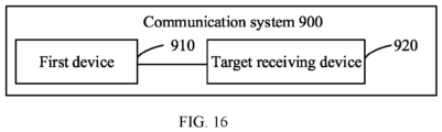
- FIG. 16 is a schematic block diagram of a communication system 900 provided in the embodiments of the present application. As shown in FIG. 16 , the communication system 900 includes a first terminal 910 and a target receiving device 920.
- the first terminal 910 may be configured to implement the corresponding functions implemented by the first terminal in the above methods
- the target receiving device 920 may be configured to implement the corresponding functions implemented by the target receiving device in the above method, which will not be repeated here for the sake of brevity.
- the processor in the embodiments of the present application may be an integrated circuit chip with signal processing capabilities.
- each step in the above method embodiments may be completed by an integrated logic circuit of hardware in a processor or instructions in a software form in the processor.
- the above processor may be a general purpose processor, a digital signal processor (DSP), an application specific integrated circuit (ASIC), a field programmable gate array (FPGA) or other programmable logic device, a discrete gate, a transistor logic device, or a discrete hardware component, which may implement or execute the disclosed methods, steps and logic block diagrams in the embodiments of the present disclosure.
- the general purpose processor may be a microprocessor, or the processor may be any conventional processor.
- the steps of the methods disclosed in conjunction with the embodiments of the present application may be directly implemented as being performd by the hardware decoding processor, or may be implemented by a combination of the hardware and software modules in the decoding processor.
- the software module may be located in a random memory, a flash memory, a read-only memory, a programmable read-only memory, an electrically erasable programmable memory, a register or other mature storage media in the art.
- the storage medium is located in the memory, and the processor reads the information in the memory and completes the steps of the above method in combination with its hardware.
- the memory in the embodiments of the present application may be a volatile (transitory) memory or a non-volatile (non-transitory) memory, or may include both volatile and non-volatile memories.
- the non-volatile memory may be a read-only memory (ROM), a programmable read-only memory (Programmable ROM, PROM), an erasable programmable read-only memory (Erasable PROM, EPROM), an electrically erasable programmable read-only memory (Electrically EPROM, EEPROM) or a flash memory.
- the volatile memory may be a random access memory (RAM), which is used as an external cache.
- RAMs such as a static random access memory (Static RAM, SRAM), a dynamic random access memory (Dynamic RAM, DRAM), a synchronous dynamic random access memory (Synchronous DRAM, SDRAM), a double data rate synchronous dynamic random access memory (Double Data Rate SDRAM, DDR SDRAM), an enhanced synchronous dynamic random access memory (Enhanced SDRAM, ESDRAM), a synchronous link dynamic random access memory (Synchlink DRAM, SLDRAM) and a direct memory bus random access memory (Direct Rambus RAM, DR RAM).
- Static RAM static random access memory
- DRAM dynamic random access memory
- DRAM synchronous dynamic random access memory
- SDRAM double data rate synchronous dynamic random access memory
- Enhanced SDRAM, ESDRAM enhanced synchronous dynamic random access memory
- Synchlink DRAM synchronous link dynamic random access memory
- Direct Rambus RAM Direct Rambus RAM
Landscapes
- Engineering & Computer Science (AREA)
- Computer Networks & Wireless Communication (AREA)
- Signal Processing (AREA)
- Quality & Reliability (AREA)
- Physics & Mathematics (AREA)
- Electromagnetism (AREA)
- Mobile Radio Communication Systems (AREA)
- Radar Systems Or Details Thereof (AREA)
Applications Claiming Priority (1)
| Application Number | Priority Date | Filing Date | Title |
|---|---|---|---|
| PCT/CN2022/114030 WO2024040403A1 (zh) | 2022-08-22 | 2022-08-22 | 无线通信的方法和设备 |
Publications (1)
| Publication Number | Publication Date |
|---|---|
| EP4580260A1 true EP4580260A1 (de) | 2025-07-02 |
Family
ID=90012090
Family Applications (1)
| Application Number | Title | Priority Date | Filing Date |
|---|---|---|---|
| EP22955952.1A Pending EP4580260A1 (de) | 2022-08-22 | 2022-08-22 | Verfahren und vorrichtung zur drahtlosen kommunikation |
Country Status (5)
| Country | Link |
|---|---|
| US (1) | US20250126572A1 (de) |
| EP (1) | EP4580260A1 (de) |
| CN (1) | CN119732123A (de) |
| MX (1) | MX2024015678A (de) |
| WO (1) | WO2024040403A1 (de) |
Families Citing this family (2)
| Publication number | Priority date | Publication date | Assignee | Title |
|---|---|---|---|---|
| CN120658309A (zh) * | 2024-03-08 | 2025-09-16 | 西安紫光展锐科技有限公司 | 通信方法、通信装置、芯片、计算机可读存储介质及计算机程序产品 |
| CN120935520A (zh) * | 2024-05-09 | 2025-11-11 | 华为技术有限公司 | 通信方法和装置 |
Family Cites Families (4)
| Publication number | Priority date | Publication date | Assignee | Title |
|---|---|---|---|---|
| US6549064B2 (en) * | 2001-02-12 | 2003-04-15 | Matrics, Inc. | Efficient charge pump apparatus |
| EP2053755A1 (de) * | 2007-10-25 | 2009-04-29 | Commissariat A L'energie Atomique | Verfahren und Vorrichtung zur Synchronisation |
| CN110324068A (zh) * | 2018-03-28 | 2019-10-11 | 上海华为技术有限公司 | 射频识别系统、组建中继网络的方法和阅读器、中继器 |
| CN114698071B (zh) * | 2020-12-31 | 2024-07-26 | 维沃移动通信有限公司 | 能量提供方法、装置及通信设备 |
-
2022
- 2022-08-22 EP EP22955952.1A patent/EP4580260A1/de active Pending
- 2022-08-22 WO PCT/CN2022/114030 patent/WO2024040403A1/zh not_active Ceased
- 2022-08-22 CN CN202280099289.XA patent/CN119732123A/zh active Pending
-
2024
- 2024-12-16 MX MX2024015678A patent/MX2024015678A/es unknown
- 2024-12-26 US US19/002,401 patent/US20250126572A1/en active Pending
Also Published As
| Publication number | Publication date |
|---|---|
| MX2024015678A (es) | 2025-02-10 |
| US20250126572A1 (en) | 2025-04-17 |
| CN119732123A (zh) | 2025-03-28 |
| WO2024040403A1 (zh) | 2024-02-29 |
Similar Documents
| Publication | Publication Date | Title |
|---|---|---|
| US20240179639A1 (en) | Wireless communication method and device | |
| WO2023159495A1 (zh) | 通信方法、终端设备、网络设备、芯片和存储介质 | |
| US20240160866A1 (en) | Wireless communication method, terminal device and network device | |
| US20250126572A1 (en) | Wireless communication method and device | |
| US20250023589A1 (en) | Wireless communication method and device | |
| US20240378402A1 (en) | Communication state indication method, terminal device, and network device | |
| US20240137194A1 (en) | Method and device for wireless communication | |
| US20240373375A1 (en) | Wireless communication method, terminal device, and energy supply node | |
| US20250247837A1 (en) | Wireless communication method and device | |
| US20240178700A1 (en) | Wireless communication method and apparatus, and communication device | |
| US20250142471A1 (en) | Method for wireless communication, terminal device, and chip | |
| US20250016604A1 (en) | Method and device for wireless communication | |
| US20250274901A1 (en) | Wireless communication method and device | |
| US20250220577A1 (en) | Wireless communication method, and devices | |
| US20250096958A1 (en) | Wireless communication method and device | |
| US20250030519A1 (en) | Wireless communication method and device | |
| US20240414767A1 (en) | Channel listening method and communication device | |
| WO2023000175A1 (zh) | 无线通信方法、第一设备和第二设备 | |
| EP4580225A1 (de) | Verfahren und vorrichtung zur drahtlosen kommunikation | |
| US20250351087A1 (en) | Wireless communication methods, network devices and terminal devices | |
| US20250133084A1 (en) | Access authentication method and device | |
| EP4608050A1 (de) | Verfahren und vorrichtung zur drahtlosen kommunikation | |
| WO2023039754A1 (zh) | 无线通信的方法、终端设备和网络设备 |
Legal Events
| Date | Code | Title | Description |
|---|---|---|---|
| STAA | Information on the status of an ep patent application or granted ep patent |
Free format text: STATUS: THE INTERNATIONAL PUBLICATION HAS BEEN MADE |
|
| PUAI | Public reference made under article 153(3) epc to a published international application that has entered the european phase |
Free format text: ORIGINAL CODE: 0009012 |
|
| STAA | Information on the status of an ep patent application or granted ep patent |
Free format text: STATUS: REQUEST FOR EXAMINATION WAS MADE |
|
| 17P | Request for examination filed |
Effective date: 20250320 |
|
| AK | Designated contracting states |
Kind code of ref document: A1 Designated state(s): AL AT BE BG CH CY CZ DE DK EE ES FI FR GB GR HR HU IE IS IT LI LT LU LV MC MK MT NL NO PL PT RO RS SE SI SK SM TR |
|
| DAV | Request for validation of the european patent (deleted) | ||
| DAX | Request for extension of the european patent (deleted) |