EP4580225A1 - Verfahren und vorrichtung zur drahtlosen kommunikation - Google Patents
Verfahren und vorrichtung zur drahtlosen kommunikation Download PDFInfo
- Publication number
- EP4580225A1 EP4580225A1 EP22955951.3A EP22955951A EP4580225A1 EP 4580225 A1 EP4580225 A1 EP 4580225A1 EP 22955951 A EP22955951 A EP 22955951A EP 4580225 A1 EP4580225 A1 EP 4580225A1
- Authority
- EP
- European Patent Office
- Prior art keywords
- signal
- time domain
- time
- backscatter
- communication
- Prior art date
- Legal status (The legal status is an assumption and is not a legal conclusion. Google has not performed a legal analysis and makes no representation as to the accuracy of the status listed.)
- Pending
Links
Images


Classifications
-
- H—ELECTRICITY
- H04—ELECTRIC COMMUNICATION TECHNIQUE
- H04L—TRANSMISSION OF DIGITAL INFORMATION, e.g. TELEGRAPHIC COMMUNICATION
- H04L5/00—Arrangements affording multiple use of the transmission path
- H04L5/003—Arrangements for allocating sub-channels of the transmission path
- H04L5/0048—Allocation of pilot signals, i.e. of signals known to the receiver
-
- H—ELECTRICITY
- H04—ELECTRIC COMMUNICATION TECHNIQUE
- H04L—TRANSMISSION OF DIGITAL INFORMATION, e.g. TELEGRAPHIC COMMUNICATION
- H04L67/00—Network arrangements or protocols for supporting network services or applications
- H04L67/01—Protocols
- H04L67/12—Protocols specially adapted for proprietary or special-purpose networking environments, e.g. medical networks, sensor networks, networks in vehicles or remote metering networks
-
- H—ELECTRICITY
- H04—ELECTRIC COMMUNICATION TECHNIQUE
- H04W—WIRELESS COMMUNICATION NETWORKS
- H04W4/00—Services specially adapted for wireless communication networks; Facilities therefor
- H04W4/70—Services for machine-to-machine communication [M2M] or machine type communication [MTC]
-
- H—ELECTRICITY
- H04—ELECTRIC COMMUNICATION TECHNIQUE
- H04W—WIRELESS COMMUNICATION NETWORKS
- H04W72/00—Local resource management
- H04W72/04—Wireless resource allocation
-
- H—ELECTRICITY
- H04—ELECTRIC COMMUNICATION TECHNIQUE
- H04W—WIRELESS COMMUNICATION NETWORKS
- H04W72/00—Local resource management
- H04W72/04—Wireless resource allocation
- H04W72/044—Wireless resource allocation based on the type of the allocated resource
- H04W72/0446—Resources in time domain, e.g. slots or frames
Definitions
- the embodiments of the present application relate to the field of communications, and in particularly, to a wireless communication method and a device.
- a zero-power consumption terminal may not actively transmit a signal, but transmit information by backscattering a carrier signal.
- some zero-power consumption terminals with powerful capabilities can also transmit information in a way of actively transmitting a signal. Therefore, in a case where the zero-power consumption terminal supports both a backscatter (back scattering) communication mode and an active transmission communication mode, how to transmit a signal is an urgent problem to be solved.
- the present application provides a wireless communication method and a device, which is conducive to balancing terminal power saving and reliable transmission of signals.
- a wireless communication method includes: determining, by a first terminal according to a time domain feature of a transmitting time of a first signal, a target transmission mode of the first signal from a plurality of types of transmission modes; where the plurality of types of transmission modes include an active transmission mode and a backscatter mode.
- a wireless communication method includes: determining, by a target receiving device according to a time domain feature of a receiving time of a first signal, a target receiving mode of the first signal from a plurality of types of receiving modes; where the plurality of types of receiving modes include a receiving mode corresponding to an active transmission mode and a receiving mode corresponding to a backscatter mode, and the target receiving device is a receiving device of the first signal.
- a terminal device is provided and the terminal device is configured to perform the method in the above first aspect or various implementations thereof.
- the terminal device includes a functional module for executing the method in the above-mentioned first aspect or various implementations thereof.
- a network device is provided, and the network device is configured to perform the method in the above second aspect or various implementations thereof.
- the network device includes a functional module for executing the method in the above-mentioned second aspect or various implementations thereof.
- the terminal device when a terminal device is going to transmit a signal, the terminal device selects a target transmission mode according to a time domain feature of a transmitting time of a signal to be transmitted, which is beneficial to balancing terminal power saving and reliable transmission of signals.
- the communication system in the embodiments of the present application may be applied to a carrier aggregation (CA) scenario, a dual connectivity (DC) scenario, or a standalone (SA) networking scenario.
- CA carrier aggregation
- DC dual connectivity
- SA standalone
- the communication system in the embodiments of the present application may be applied to an unlicensed spectrum, and the unlicensed spectrum may be considered as a shared spectrum; or the communication system in the embodiments of the present application may be applied to a licensed spectrum, and the licensed spectrum may be considered as an unshared spectrum.
- the terminal device may be referred to as a user equipment (UE), an access terminal, a user unit, a user station, a mobile station, a mobile console, a remote station, a remote terminal, a mobile device, a user terminal, a terminal, a wireless communication device, a user agent, or a user apparatus.
- UE user equipment
- the network device may be a device used for communicating with a mobile device.
- the network device may be an access point (AP) in WLAN, a base transceiver station (BTS) in GSM or CDMA, or a base station (NodeB, NB) in WCDMA; or the network device may be an evolutional Node B (eNB or eNodeB) in LTE, a relay station or access point, a network device (e.g., gNB) in a vehicle-mounted device, a wearable device or an NR network, a network device in a cellular Internet of Things, a network device in a cellular passive Internet of Things, a network device in a future evolved public land mobile network (PLMN), or a network device in an NTN network.
- AP access point
- BTS base transceiver station
- NodeB, NB base station
- NB base station
- NB base station
- NB base station
- NB base station
- NB base station
- NB base
- the network device may have a mobile characteristic.
- the network device may be a mobile device.
- the network device may be a satellite or a balloon station.
- the satellite may be a low earth orbit (LEO) satellite, a medium earth orbit (MEO) satellite, a geostationary earth orbit (GEO) satellite, or a high elliptical orbit (HEO) satellite.
- the network device may be a base station provided on land, water, or other places.
- the network device may provide services for a cell, and the terminal device communicates with the network device through a transmission resource (e.g., a frequency domain resource, or a spectrum resource) used by the cell.
- the cell may be a cell corresponding to the network device (e.g., the base station).
- the cell may belong to a macro base station, or belong to a base station corresponding to small cells.
- the small cells may include: a metro cell, a micro cell, a pico cell, a femto cell, etc. These small cells have characteristics of small coverage and low transmit power, and are suitable for providing high-rate data transmission services.
- the terminal device may be a station (ST) in WLAN, or may be a cellular phone, a cordless phone, a session initiation protocol (SIP) phone, a wireless local loop (WLL) station, a personal digital assistant (PDA) device, a handheld device with a wireless communication function, a computing device or any other processing device connected to a wireless modem, a vehicle-mounted device, a wearable device, a terminal device in a next-generation communication system (such as an NR network), a terminal device in a future evolved public land mobile network (PLMN), a terminal device in a cellular Internet of Things, a terminal device in a cellular passive Internet of Things, or the like.
- ST station
- WLAN Wireless Local Area Network
- the terminal device may be deployed on land, which includes indoor or outdoor, handheld, wearable or vehicle-mounted; or the terminal device may be deployed on water (e.g., on a ship); or the terminal device may be deployed in the air (e.g., on an airplane, a balloon, a satellite).
- the terminal device may be a mobile phone, a pad, a computer with a wireless transceiving function, a virtual reality (VR) terminal device, an augmented reality (AR) terminal device, a wireless terminal device in industrial control, a wireless terminal device in self-driving, a wireless terminal device in remote medical, a wireless terminal device in smart grid, a wireless terminal device in transportation safety, a wireless terminal device in smart city, a wireless terminal device in smart home, or the like.
- VR virtual reality
- AR augmented reality
- the power supply signal is a power source from which the zero-power consumption device harvests power.
- the carrier may be a base station, a smart phone, a smart gateway, a charging station, a micro base station, or the like.
- the frequency band of a radio wave used for power supply may be a low frequency, an intermediate frequency, or a high frequency.
- the power supply signal may be an existing signal in 3GPP standards, such as a sounding reference signal (SRS), a physical uplink shared channel (PUSCH), a physical random access channel (PRACH), a physical uplink control channel (PUCCH), a physical downlink control channel (PDCCH), a physical downlink shared channel (PDSCH), or a physical broadcast channel (PBCH).
- SRS sounding reference signal
- PUSCH physical uplink shared channel
- PRACH physical random access channel
- PUCCH physical uplink control channel
- PUCCH physical downlink control channel
- PDSCH physical downlink shared channel
- PBCH physical broadcast channel
- the power supply signal may be a WIFI signal or a Bluetooth signal.
- Trigger signal also referred to as scheduling signal
- the trigger signal is used to trigger or schedule the zero-power consumption device to transmit data.
- the radio wave used for triggering or scheduling may have a low frequency, an intermediate frequency, or high frequency.
- the radio wave used for triggering or scheduling may be a sine wave, a square wave, a triangle wave, a pulse, or a rectangular wave.
- the trigger signal may be a continuous wave or a non-continuous wave (that is, a certain period of interruption is allowed).
- the trigger signal may be an existing signal in 3GPP standards, such as a SRS, a PUSCH, a PRACH, a PUCCH, a PDCCH, a PDSCH, a PBCH, a WIFI signal, or a Bluetooth signal.
- 3GPP standards such as a SRS, a PUSCH, a PRACH, a PUCCH, a PDCCH, a PDSCH, a PBCH, a WIFI signal, or a Bluetooth signal.
- the carrier signal is used for the zero-power consumption device to generate a backscatter signal.
- the zero-power consumption device may modulate a received carrier signal according to the information that needs to be sent, so as to form the backscatter signal.
- the carrier may be a base station, a smart phone, or a smart gateway.
- the radio wave used as the carrier signal may have a low frequency, an intermediate frequency, or a high frequency.
- the carrier signal may be a continuous wave or a non-continuous wave (that is, a certain period of interruption is allowed).
- the carrier signal may also be implemented by a newly added signal, e.g., a newly added signal dedicated to generating a backscatter signal.
- the power supply signal, the scheduling signal and the carrier signal may be the same signal or different signals.
- the power supply signal may be used as the carrier signal
- the scheduling signal may also be used as the carrier signal.
- the zero-power consumption terminal does not support transmitting a signal actively, but transmit information by backscatter a carrier signal.
- some zero-power terminals with powerful capabilities can also transmit information in a way of actively transmitting a signal. Therefore, in a case where the zero-power consumption terminal supports both a backscatter communication mode and an active transmission communication mode, how to transmit a signal is an urgent problem to be solved.
- FIG. 6 is a schematic diagram of a wireless communication method 200 according to the embodiments of the present application. As shown in FIG. 6 , the method 200 includes at least part of the following contents.
- a first terminal determines a target transmission mode of a first signal from a plurality of types of transmission modes, according to a time domain feature of a transmitting time of the first signal; where the plurality of types of transmission modes include an active transmission mode and a backscatter mode.
- a target receiving device is a network device. That is, the first signal may be an uplink signal.
- the first signal may be any uplink signal; alternatively, the first signal may be replaced with an uplink channel, uplink information, or uplink data.
- the power amplifier device may refer to a PA, an LNA, or other devices with power amplification functions, such as a transistor, and a tunnel diode.
- the primary transmitter supports orthogonal frequency-division multiplexing (OFDM) modulation.
- the auxiliary transmitter supports amplitude shift keying (ASK) modulation, frequency shift keying (FSK), phase shift keying (PSK) modulation, or on-off keying (OOK) modulation.
- the primary transmitter and the backscatter transmitter may be independent modules; alternatively, the primary transmitter and the backscatter transmitter may include different functional modules of a transmitter of the first terminal, for example, the primary transmitter may include functional modules such as a local oscillator, a crystal oscillator, and an LNA, while the backscatter transmitter does not include the above functional modules.
- the first terminal further includes a primary receiver (also called a conventional receiver) and an auxiliary receiver.
- a primary receiver also called a conventional receiver
- the power consumption of the primary receiver is higher than that of the auxiliary receiver, and/or the complexity of the primary receiver is higher than that of the auxiliary receiver.
- the primary receiver may have a relative high information processing capability, such as supporting a large bandwidth (e.g., 100 MHz), or receiving and processing high-rate information.
- a relative high information processing capability such as supporting a large bandwidth (e.g., 100 MHz), or receiving and processing high-rate information.
- the auxiliary receiver may be used to receive a signal transmitted through the backscatter mode.
- the auxiliary receiver may have a relative low information processing capability, such as only supporting a narrowband, or receiving and processing low-rate information.
- the primary receiver and the auxiliary receiver may be independent modules; alternatively, the primary receiver and the auxiliary receiver may include different functional modules of the receiver of the first terminal; alternatively, the primary receiver and the auxiliary receiver may share different functional modules, for example, sharing a signal amplification module.
- the first terminal includes only one receiver, which is used to receive signals transmitted through the active transmission mode and signals transmitted through the backscatter mode.
- the first signal may be scheduled by the network device, or scheduled by the target receiving device.
- the first terminal may perform communication immediately after receiving scheduling information (or in other words, control signaling, or a scheduling command); alternatively, the first terminal may perform communication at the next time unit after receiving the scheduling information; alternatively, the first terminal may perform communication at a time unit after the receiving time of the scheduling information and having a first time offset relative to the receiving time.
- scheduling information or in other words, control signaling, or a scheduling command
- the first terminal may perform communication at the next time unit after receiving the scheduling information
- the first terminal may perform communication at a time unit after the receiving time of the scheduling information and having a first time offset relative to the receiving time.
- a unit of the next time unit may be a symbol, a slot, a subframe, a frame, a millisecond, a second, a minute, etc; or the unit of the next time unit may be a backscatter time unit.
- the unit of the first time offset may be a symbol, a slot, a subframe, a frame, a millisecond, a second, a minute, etc; or the unit of the first time offset may be a backscatter time unit.
- the first signal may be a scheduling-free signal.
- the network device or the target receiving device may schedule the first terminal to perform periodic communication, and in each period, the transmitting time of the first signal may be configured by the network device or the target receiving device.
- the first signal represents communication autonomously initiated by the first terminal.
- the method 200 further includes: obtaining, by the first terminal, time domain configuration of the first signal.
- the time domain configuration of the first signal may be indicated by the network device or the target receiving device, or may be determined by the first terminal.
- the time domain configuration of the first signal may include the transmitting time of the first signal.
- the time domain configuration of the first signal may further include a transmission duration of the first signal, or an end time of the first signal.
- the time domain configuration of the first signal is determined according to the indication of the network device or the target receiving device.
- the time domain configuration of the first signal is determined according to a preset (or default) time domain configuration, or a time domain configuration selected from multiple time domain configurations is determined as the time domain configuration of the first signal.
- the first time domain configuration of the multiple pre-configured time domain configurations is determined as the time domain configuration of the first signal.
- the multiple time domain configurations may be predefined or pre-configured.
- the time domain feature of the transmitting time of the first signal may refer to the type of time domain resources corresponding to the transmitting time of the first signal, or may refer to the feature of the transmitting time of the first signal in the time domain, e.g., whether the transmitting time corresponds to a certain transmission mode.
- the target transmission mode of the first signal is determined according to the distribution of time domain resources.
- time domain resources (used) for backscatter communication also called backscatter communication time domain resources
- time domain resources (used) for active transmission communication also called active transmission communication time domain resources
- the first terminal may determine the target transmission mode of the first signal according to the distribution of the backscatter communication time domain resources and the active transmission communication time domain resources.
- the distribution of the backscatter communication time domain resources and the active transmission communication time domain resources in the time domain is referred to as a pattern, or a time domain configuration of dual-mode communication.
- backscatter communication time domain resources and active transmission communication time domain resources may be distributed in the time domain in one or more patterns, which is not limited in the present application.
- the backscatter communication time domain resources may refer to time domain resources that may be used by the first terminal to perform the backscatter communication. That is, the first terminal needs to complete the entire backscatter communication process on these time domain resources.
- the backscatter communication time domain resources may refer to time domain resources on which the backscatter communication may be initiated by the first terminal. If the on-going backscatter communication is not completed at the end of these time domain resources, the first terminal may continue the backscatter communication.
- the active transmission communication time domain resources may refer to time domain resources that may be used by the first terminal to perform the active transmission communication. That is, the first terminal needs to complete the entire active transmission communication process on these time domain resources.
- the active transmission communication time domain resources may refer to time domain resources on which the active transmission communication may be initiated by the first terminal. If the active transmission communication is not completed at the end of these time domain resources, the first terminal may continue the active transmission communication.
- the backscatter communication time domain resources and the active transmission communication time domain resources are distributed based on a first pattern.
- the first pattern is predefined.
- the first pattern is configured by the target receiving device of the first signal.
- the target receiving device is a network device
- the first pattern may be configured via any downlink signaling, such as radio resource control (RRC) signaling, a media access control control element (MAC CE), or downlink control information (DCI).
- RRC radio resource control
- MAC CE media access control control element
- DCI downlink control information
- the target receiving device is the second terminal, and the first pattern may be configured via any sidelink signaling, such as sidelink RRC signaling, or sidelink control information (SCI).
- sidelink signaling such as sidelink RRC signaling, or sidelink control information (SCI).
- SCI sidelink control information
- the first pattern may be pre-configured by the target receiving device of the first signal, or may be configured when the target receiving device schedules the first signal.
- the first pattern is configured by the network device.
- the first pattern may be configured via any downlink signaling, such as RRC signaling, a MAC CE, or DCI.
- RRC signaling such as RRC signaling, a MAC CE, or DCI.
- the first pattern may be pre-configured by the network device, or may be configured when the network device schedules the first signal.
- the first pattern may be determined by the first terminal.
- the first pattern is periodic or aperiodic.
- the backscatter communication time domain resources and active transmission communication time domain resources are distributed in the time domain in the first pattern over a first time period, and are distributed in the time domain in a second pattern over a second time period.
- a unit of the period of the first pattern may be a symbol, a slot, a subframe, a frame, a millisecond, a second, or a minute, e.g., 1 frame or 10 frames.
- the target receiving device is the second terminal, and the second terminal may configure the first offset for the first terminal.
- the first offset may be configured via any sidelink signaling, such as sidelink RRC signaling, or SCI.
- sidelink RRC signaling such as sidelink RRC signaling, or SCI.
- the first offset may be pre-indicated by the target receiving device of the first signal, or may be indicated when the target receiving device schedules the first signal.
- the target receiving device of the first signal may directly indicate a specific offset, or may indicate an index corresponding to the first offset.
- a plurality of offsets are preconfigured, each of the offsets corresponds to an index, and the target receiving device may indicate a specific offset through an index.
- the first offset is configured by the network device.
- the network device may directly indicate a specific offset, or may indicate an index corresponding to the first offset.
- a plurality of offsets are preconfigured, each of the offsets corresponds to an index, and the network device may indicate a specific offset through an index.
- the first time domain position may be the time when the first terminal receives the scheduling information of the first signal, or may be the time unit occupied by the first terminal when the first terminal receives the scheduling information, such as a symbol, a slot, a subframe, or a frame.
- the first time domain position is the time domain position indicated by the target receiving device of the first signal or the network device.
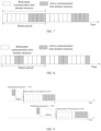
- FIG. 9 is a schematic diagram of another distribution pattern of time domain resources provided in the embodiments of the present application.
- the start position of the pattern may be a time position latter than and having an offset relative to the time position where the scheduling information is received.
- the offsets set for different UEs may be the same or different. For example, for UE1, a time position with Offset 1 after the reception of the scheduling information is determined as the start position of the pattern; and for UE2, a time position with Offset 2 after the reception of the scheduling information is determined as the start position of the pattern. Offset 1 and Offset 2 may be the same or different.
- the way to represent the first pattern is not limited in the present application.
- the first pattern may be represented as a bitmap.
- specific positions of the backscatter communication time domain resources and the active transmission communication time domain resources may be directly indicated as the first pattern, for example, a start position, or a start position and a time duration, or a start position and an end position of the backscatter communication time domain resources and the active transmission communication time domain resources may be indicated as the first pattern.
- the network device or the target receiving device may be configured to directly indicate a specific pattern, or to indicate index information of the first pattern, e.g., the index information corresponding to the first pattern in multiple patterns.
- the multiple patterns may be predefined, or may be pre-configured by the network device or the target receiving device.
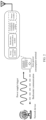
- the first pattern is represented by a first bitmap
- the first bitmap includes a plurality of bit groups, each bit group includes one or more bits, each bit group corresponds to N time units, and a value of each bit group is used to indicate a resource type of corresponding N time units, where N is a positive integer.
- units of the N time units may be symbols, slots, subframes, frames, milliseconds, seconds, minutes, etc, which are not limited in the present application.
- N may be equal to 1 or greater than 1.
- the number of bits included in the first bitmap and the number of time units corresponding to each bit group may be fixed, or may be flexibly configured, which is not limited in the present application.
- the value of each bit group is used to indicate that the corresponding N time units are time domain resources for backscatter communication, or time domain resources for active transmission communication, or flexible time domain resources.
- the flexible time domain resources may refer to that the N time units may be used as time domain resources for backscatter communication or time domain resources for the active transmission communication.
- each bit group includes 2 bits, and different values of the 2 bits are used to indicate that the corresponding N time units are the backscatter communication time domain resources, the active transmission communication time domain resources, or the flexible time domain resources. For example, when the 2 bits have a value of "00”, it indicates that the corresponding N time units are backscatter communication time domain resources; when the 2 bits have a value of "01”, it indicates that the corresponding N time units are active transmission communication time domain resources; and when the 2 bits have a value of "10”, it indicates that the corresponding N time units are flexible time domain resources.
- the above correspondence between values and resource types is only an example. The present application does not limit the correspondence except that the correspondence should guarantee that different resource types correspond to different values of a bit group.
- the value of each bit group is used to indicate whether the corresponding N time units are time domain resources for backscatter communication or time domain resources for active transmission communication.
- each bit group includes 1 bit, and different values of the 1 bit are used to indicate whether the corresponding N time units are backscatter communication time domain resources or active transmission communication time domain resources. For example, if the 1 bit has a value of "0", it indicates that the corresponding N time units are time domain resources for backscatter communication; and if the 1 bit has a value of "1", it indicates that the corresponding N time units are time domain resources for active transmission communication.
- the above correspondence between values and resource types is only an example. The present application does not limit the correspondence except that the correspondence should guarantee that different resource types correspond to different values of a bit group.
- Embodiment 1-1 Specific implementations for determining the target transmission mode of the first signal according to the transmitting time of the first signal and the first pattern will be described below through Embodiment 1-1 and Embodiment 1-2.
- S210 includes: determining the target transmission mode of the first signal according to the time domain resource type corresponding to the transmitting time of the first signal in the first pattern.
- the target transmission mode of the first signal is the backscatter mode.
- the target transmission mode of the first signal is the active transmission mode.
- the backscatter mode is selected for transmission of the first signal.
- the time domain resource type corresponding to the transmitting time of the first signal is the backscatter communication time domain resource
- the active transmission mode is selected for transmission of the first signal.
- the method 200 further includes:
- the time domain resources used may include backscatter communication time domain resources only, or may include backscatter communication time domain resources and active transmission communication time domain resources. For example, if time domain resources required for transmitting the first signal via the backscatter mode exceed available backscatter communication time domain resources when the first terminal initiates backscatter communication, the time domain resources used by the first terminal to transmit the first signal may include backscatter communication time domain resources and active transmission communication time domain resources.
- the method 200 further includes:
- the time domain resources used may include active transmission communication time domain resources only, or may include active transmission communication time domain resources and backscatter communication time domain resources. For example, if time domain resources required for transmitting the first signal via the active transmission mode exceed available active transmission communication time domain resources when the first terminal initiates active transmission communication, the time domain resources used by the first terminal to transmit the first signal include active transmission communication time domain resources and backscatter communication time domain resources.
- the target receiving device may turn on a receiver (e.g., the auxiliary receiver) corresponding to the backscatter communication within the range of the backscatter communication time domain resources, or in other words, receive a signal using a receiving mode corresponding to backscatter communication; alternatively, the target receiving device may turn on a receiver (e.g., the primary receiver) corresponding to the active transmission communication within the range of the active transmission communication time domain resources, or in other words, receive a signal using a receiving mode corresponding to the active transmission communication.
- a receiver e.g., the primary receiver
- the target receiving device turns on the auxiliary receiver at the backscatter communication time domain resource corresponding to the transmitting time of the first signal or at an earlier time position than that.
- the target receiving device turns on the primary receiver at the active communication time domain resource corresponding to the transmitting time of the first signal or at an earlier time position than that.
- the target receiving device may turn off the receiver corresponding to the backscatter communication within the range of active transmission communication time domain resources, or in other words, no longer receive signals using the receiving mode corresponding to the backscatter communication; alternatively, the target receiving device may turn off the receiver corresponding to the backscatter communication after the reception of the first signal is completed within active transmission communication time domain resources.
- the first terminal occupies the active transmission communication time domain resources to perform the backscatter communication.
- the target receiving device may turn off the receiver corresponding to the active transmission communication within the range of backscatter communication time domain resources, or in other words, no longer receive signals using the receiving mode corresponding to the active transmission communication; alternatively, the target receiving device may turn off the receiver corresponding to the active transmission communication after the reception of the first signal is completed within backscatter communication time domain resources.
- the first terminal occupies the backscatter communication time domain resources to perform the active transmission communication.
- S210 includes: determining the target transmission mode of the first signal, according to the time domain resource type corresponding to the transmitting time of the first signal in the first pattern and the size of the remaining time domain resources (e.g., the number of remaining available time domain resources) with such a time domain resource type after the transmitting time.
- the first terminal besides the time domain resource type corresponding to the transmitting time of the first signal, the first terminal further considers the size of the remaining available time domain resources, which is conducive to ensuring reliable transmission of the first signal.
- the first terminal may determine the target transmission mode of the first signal according to whether the size of the remaining time domain resources for backscatter communication meets a backscatter communication duration required for the first signal (that is, whether the remaining time domain resources for backscatter communication are sufficient to complete the entire backscatter communication process of the first signal).
- the backscatter mode is determined to be used for the transmission of the first signal.
- the active transmission mode is determined to be used for the transmission of the first signal, or the backscatter mode and the active transmission mode are determined to be used for the transmission of the first signal.
- that the first terminal transmits the first signal using the backscatter mode and the active transmission mode may refer to that:
- the size of the remaining time domain resources for backscatter communication meets the backscatter communication duration of the first signal may refer to that:
- the size of the remaining time domain resources for backscatter communication does not meet the backscatter communication duration of the first signal may refer to that:
- the first terminal may determine the target transmission mode of the first signal according to whether the size of the remaining time domain resources for active transmission communication meets the active transmission communication duration required by the first signal (that is, whether the remaining active transmission communication time domain resources are sufficient to complete the entire active transmission communication process of the first signal).
- the active transmission mode is determined to be used for the transmission of the first signal.
- the backscatter mode is determined to be used for the transmission of the first signal, or the active transmission mode and backscatter mode are determined to be used for the transmission of the first signal.
- that the first terminal transmits the first signal using the active transmission mode and the backscatter modes may refer to that:
- the size of the remaining time domain resources for active transmission communication meets the active transmission communication duration of the first signal may refer to that:
- the size of the remaining time domain resources for active transmission communication does not meet the active transmission communication duration of the first signal may refer to that:
- the first terminal may transmit the first signal on the active transmission communication time domain resources. That is, time domain resources used for transmission of the first signal performed by the first terminal using the active transmission mode may include active transmission communication time domain resources only.
- the first terminal may transmit the first signal on the backscatter communication time domain resources. That is, time domain resources used for transmission of the first signal performed by the first terminal using the backscatter mode may include backscatter communication time domain resources only.
- the first terminal selects the backscatter mode to transmit the first signal.
- the time domain resource type corresponding to the transmitting time of the first signal is backscatter communication time domain resources, and the remaining continuous backscatter communication time domain resources are sufficient for the first terminal to transmit the first signal using the backscatter mode, then the first terminal selects the backscatter mode to transmit the first signal.
- the time domain resource type corresponding to the transmitting time of the first signal is active transmission communication time domain resources, and the remaining continuous active transmission communication time domain resources are sufficient for the first terminal to transmit the first signal using the active transmission mode, then the first terminal selects the active transmission mode to transmit the first signal.
- the first terminal selects the active transmission mode to transmit the first signal, for example, transmit the first signal on subsequent active transmission communication time domain resources.
- the target receiving device may turn on a receiver (e.g., the auxiliary receiver) corresponding to the backscatter communication within the range of the backscatter communication time domain resources, or in other words, receive a signal using the receiving mode corresponding to backscatter communication; alternatively, the target receiving device may turn on a receiver (e.g., the primary receiver) corresponding to the active transmission mode within the range of the active transmission communication time domain resources, or in other words, receive a signal using the receiving mode corresponding to the active transmission communication.
- a receiver e.g., the primary receiver
- the auxiliary receiver is turned on at the backscatter communication time domain resource corresponding to the transmitting time of the first signal or at an earlier time position than that.
- the primary receiver is turned on at the active transmission communication time domain resource corresponding to the transmitting time of the first signal or at an earlier time position than that.
- the target receiving device may turn off the receiver corresponding to the backscatter communication within the range of active transmission communication time domain resources, or in other words, no longer receive signals using the receiving mode corresponding to the backscatter communication.
- the target receiving device may turn off the receiver corresponding to the active transmission communication within the range of backscatter communication time domain resources, or in other words, no longer receive the signal using the receiving mode corresponding to the active transmission communication.
- the target transmission mode of the first signal is determined according to a switching time of transmission modes (or called switching time configuration of dual-mode transmission).
- the switching time of transmission modes includes a switching time from the active transmission mode to the backscatter mode and/or a switching time from the backscatter mode to the active transmission mode.
- S210 may include:
- a transmission mode before the switching time is the first transmission mode
- a transmission mode after the switching time is the second transmission mode.
- the first transmission mode is determined as the target transmission mode of the first signal; otherwise, the second transmission mode is determined as the target transmission mode of the first signal.
- the first transmission mode is the active transmission mode
- the second transmission mode is the backscatter mode
- the first transmission mode is the backscatter mode
- the second transmission mode is the active transmission mode
- time domain resources for backscatter communication and time domain resources for active transmission communication are determined based on the switching time. For example, if the transmission mode before the switching time is the first transmission mode, and the transmission mode after the switching time is the second transmission mode, then time domain resources before the switching time are time domain resources for the first transmission mode and time domain resources after the switching time are time domain resources for the second transmission mode.
- S210 may include:
- time domain resources before the switching time are time domain resources for the first transmission mode
- time domain resources after the switching time are time domain resources for the second transmission mode.
- the transmitting time of the first signal is earlier than the switching time
- the time domain resource type corresponding to the transmitting time of the first signal is time domain resources for the first transmission mode, and thus it can be determined that the first transmission mode is used for transmission of the first signal; otherwise, the second transmission mode is used for transmission of the first signal.
- a position of the switching time in the time domain is predefined.
- the position of the switching time in the time domain is configured by the network device.
- the specific configuration method reference may be made to the way for configuring the first pattern, which will not be repeated here.
- the position of the switching time in the time domain is configured by the target receiving device of the first signal.
- the target receiving device of the first signal For the specific configuration method, reference may be made to the way for configuring the first pattern, which will not be repeated here.
- the position of the switching time in the time domain is periodic.
- the unit of the period may be a symbol, a slot, a subframe, a frame, a millisecond, a second, a minute, etc.
- the period may be 1 frame or 10 frames.
- each period there may be one switching time or a plurality of switching time.
- a transmission mode before the first switching time is a third transmission mode
- a transmission mode between the first switching time and the second switching time is a fourth transmission mode
- a transmission mode after the second switching time is a fifth transmission mode.
- the third transmission mode is different from the fourth transmission mode
- the fourth transmission mode is different from the fifth transmission mode.
- the third transmission mode may be the backscatter mode
- the fifth transmission mode may be the active transmission mode
- the sixth transmission mode may be the backscatter mode
- the third transmission mode may be the active transmission mode
- the fifth transmission mode may be the backscatter mode
- the sixth transmission mode may be the active transmission mode
- the third transmission mode may be the active transmission mode
- the fifth transmission mode may be the active transmission mode and the backscatter mode
- the sixth transmission mode may be the backscatter mode
- the third transmission mode may be the backscatter mode
- the fifth transmission mode may be the backscatter mode and the active transmission mode
- the sixth transmission mode may be the active transmission mode
- the position of the switching time is fixed.
- the switching time is distributed periodically, and the switching time has the same position within different periods.
- FIG. 12 is a schematic diagram illustrating the distribution of the switching time provided in the embodiments of the present application. As shown in FIG. 12 , the switching time has the same position within different periods. For example, a period is a frame, the transmission mode before the switching time is the first transmission mode, and the transmission mode after the switching time is the second transmission mode.
- the position of the switching time is variable, or in other words, floating.
- a reference for determining the position of the switching time is the third time domain position.
- the third time domain position is variable.
- a start position of the switching time is the third time domain position.
- the start position of the switching time is a fourth time domain position
- the fourth time domain position has a second offset relative to the third time domain position.
- the unit of the second offset may be a symbol, a slot, a subframe, a frame, a millisecond, a second, or a minute.
- the same second offset or different second offsets may be set for different terminal devices.
- the second offset is predefined.
- the second offset is configured by the network device.
- the specific configuration method reference may be made to the specific implementations of configuring the first offset in Embodiment 1, which will not be repeated here.
- the second offset is configured by the target receiving device of the first signal.
- the third time domain position is the time domain position at which the first terminal receives the scheduling information of the first signal.
- the third time domain position may be the time when the first terminal receives the scheduling information of the first signal, or may be the time unit occupied by the first terminal when the first terminal receives the scheduling information, such as a symbol, a slot, a subframe, or a frame.
- the third time domain position is the time domain position indicated by the target receiving device of the first signal or the network device.
- the third time domain position may be indicated by the target receiving device or the network device through the scheduling information, or may be indicated through other information. That is, the target receiving device or the network device may indicate the scheduling information and the third time domain position through the same signaling or different signaling.
- FIG. 13 is a schematic diagram illustrating another distribution of the switching time provided in the embodiments of the present application.
- the scheduling information may be used to directly indicate the position of the switching time, or the time domain position at which the scheduling information is received (i.e., the third time domain position) may be used as the reference for determining the position of the switching time. For example, a time position latter than and having a second offset relative to the time domain position at which the scheduling information is determined as the position of the switching time.
- the target transmission mode of the first signal is determined according to a time window, and the time window corresponds to the first transmission mode.
- time domain resources for backscatter communication and time domain resources for active transmission communication are determined based on the time window.
- the first transmission mode is the active transmission mode.
- the time window is also called an active transmission time window.
- the first transmission mode is the backscatter mode.
- the time window is also called a backscatter time window.
- the time window corresponds to the backscatter mode, time domain resources within the time window are used for the backscatter communication, and time domain resources outside the time window are used for the active transmission communication. That is, the first terminal may perform the backscatter communication within the time window, in other words, the entire backscatter communication process is performed within the time window. The first terminal may perform the active transmission communication outside the time window, in other words, the entire active transmission communication process is performed outside the time window.
- the time window corresponds to the backscatter mode
- time domain resources within the time window are used for the first terminal to initiate the backscatter communication
- time domain resources outside the time window are used for the active transmission communication and/or the backscatter communication. That is, the first terminal may initiate the backscatter communication within the time window. In this case, the backscatter communication process may occupy time domain resources outside the time window.
- the time window corresponds to the active transmission mode, time domain resources within the time window are used for the active transmission communication, and time domain resources outside the time window are used for the backscatter communication. That is, the first terminal may perform the active transmission communication within the time window, in other words, the entire active transmission communication process is performed within the time window. The first terminal may perform the backscatter communication outside the time window, in other words, the entire backscatter communication process is performed outside the time window.
- the time window corresponds to the active transmission mode
- time domain resources within the time window are used for the first terminal to initiate the active transmission communication
- time domain resources outside the time window are used for the active transmission communication and/or the backscatter communication. That is, the first terminal may initiate the active transmission communication within the time window. In this case, the active transmission communication process may occupy time domain resources outside the time window.
- the time window is predefined.
- the time window is configured by the network device.
- the specific configuration method reference may be made to the way for configuring the first pattern, which will not be repeated here.
- the time window is configured by the target receiving device of the first signal.
- the network device or the target receiving device may directly indicate a specific position of the time window, or may indicate index information corresponding to the position of the time window, e.g., an index of a target time window of a plurality of time windows.
- the plurality of time windows may be predefined, or pre-configured (i.e., configured in advance).
- the network device or the target receiving device may indicate a length of the time window only, e.g., directly indicate a specific time length,
- he network device or the target receiving device may indicate a ratio of the length of the time window to the length of the period, for example, when indicating 1/2, it means that the length of the time window occupies 1/2 of the length of the period.
- the start position of the time window may be the start position of the period.
- the time window is periodic, or may be aperiodic.
- the time window has different start positions and/or time lengths in different time periods.
- the unit of the period of the time window may be a symbol, a slot, a subframe, or a frame.
- the unit of THE period of the time window may be a millisecond, a second, a minute, an hour, etc.
- the period of the time window may be configured by the network device, or may be configured by the target receiving device, or may be predefined.
- the period of the time window may be configured through semi-static signaling or dynamic signaling.
- the period of the time window may be configured before the first signal is scheduled, or may be indicated by scheduling information used for transmitting the first signal.
- the position of the time window is determined according to first information, and the first information includes at least one of the following: a time length of the time window, a start position of the time window, an end position of the time window, an offset of the start position of the time window relative to a reference time domain position, an offset of the end position of the time window relative to a reference time domain position, period information of the time window, or a ratio of the time length of the time window to a period of the time window.
- the end position of the time window may be indicated by the network device or the target receiving device, or may be determined with reference to a seventh time domain position, that is, the seventh time domain position is a reference time domain position.
- the time length of the time window may be indicated by the network device or the target receiving device, or may be predefined.
- the unit of the time length of the time window may be a symbol, a slot, a subframe, or a frame; alternatively, the unit of the time length of the time window may be a millisecond, a second, a minute, or an hour; alternatively, the unit of the time length of the time window may be represented by a proportion of the time length of the time window to the period length of the time window.
- the position of the time window is fixed.
- the time windows are distributed periodically, and the distribution of the time windows in different period is the same.
- each period there may be a time window or a plurality of time windows.
- the plurality of time windows may correspond to the same transmission mode, or may correspond to different transmission modes.
- FIG. 14 is a schematic diagram illustrating the distribution of a time window provided in the embodiments of the present application. As shown in FIG. 14 , the time window has the same position in different periods.
- the position of the time window is variable.
- the start position of the time window is variable.
- the start position of the time window is determined with reference to a fifth time domain position, and the fifth time domain position is variable.
- the start position of the time window is the fifth time domain position.
- the start position of the time window is a sixth time domain position
- the sixth time domain position has a third offset relative to the fifth time domain position
- the present application does not limit the unit of the third offset.
- the unit of the third offset may be a symbol, a slot, a subframe, a frame, a millisecond, a second, or a minute.
- the same third offset or different third offsets may be set for different terminal devices.
- the third offset is predefined.
- the third offset is configured by the network device.
- the specific configuration method reference may be made to the specific implementations of configuring the first offset in Embodiment 1, which will not be repeated here.
- the third offset is configured by the target receiving device of the first signal.
- the fifth time domain position is the time domain position at which the first terminal receives the scheduling information of the first signal.
- the fifth time domain position may be the time when the first signal receives the scheduling information, or may be the time unit occupied by first terminal when the first terminal receives the scheduling information, such as a symbol, a slot, a subframe, or a frame.
- the fifth time domain position is the time domain position indicated by the target receiving device of the first signal or the network device
- the fifth time domain position may be indicated by the target receiving device or the network device through the scheduling information, or may be indicated through other information. That is, the target receiving device or the network device may indicate the scheduling information and the fifth time domain position through the same signaling or different signaling.
- FIG.15 is a schematic diagram illustrating another distribution of the time window provided in the embodiments of the present application.
- the start position of the time window may be determined by the first terminal by referring to the time domain position (i.e., the fifth time domain position) at which the scheduling information is received.
- the time domain position at which the scheduling information is received is determined as the start position of the time window.
- S210 may include:
- the time window is the backscatter time window.
- the transmitting time of the first signal is within the time window, the first signal is transmitted via the backscatter mode; otherwise, the first signal is transmitted via the active transmission mode.
- the time window is the active transmission time window. In this case, if the transmitting time of the first signal is within the time window, then the first signal is transmitted via the active transmission mode; otherwise, the first signal is transmitted via the backscatter mode.
- the coverage areas within which different types of zero-power terminals perform backscatter communication may be different.
- a coverage area may be affected by factors such as an operating frequency, a receiver sensitivity of the target receiving device, a power consumption of backscatter communication, a path loss, and a power amplification factor of a zero-power terminal.
- the target receiving device is a network device
- the differences in uplink and downlink coverage areas for three types of zero-power terminals denoted as UE1, UE2 and UE3 to perform the backscatter communication will be described.
- UE1 does not have a power-storage capability and harvests power mainly from wireless radio frequency signals, and UE1 does not have an LNA.
- UE2 has some power-storage capabilities and harvests power mainly from wireless radio frequency signals, and UE2 has an LNA.
- UE3 can harvest power by using multiple types of power-harvesting manners (that is, in addition to harvest power from wireless radio frequency signals, UE3 may also harvest power from other ambient signals), and also has the power-storage capability; alternatively, UE3 has its own power supply and does not need to perform power harvesting.
- UE3 has an LNA.
- the maximum communication distances from UE to the network device in a descending order is UE3>UE2>UE1.
- the maximum communication distances from the network device to the UEs in a descending order is UE3>UE2>UE1.
- the operating frequency of the network device is 920 Mhz
- the equivalent isotropiccally radiated power (EIRP) of the network device is 30 dBm
- the receiver sensitivity of the network device is -95 dBm
- antenna gains of the three types of zero-power terminals are all 2 dBi
- backscatter losses of the three types of zero-power terminals are all 5 dBm.
- the requirement of UE1 for the minimum received power for receiving downlink signal may be -20 dBm
- the requirement of UE2 for the minimum received power for receiving downlink signal may be -30 dBm
- the requirement of UE3 for the minimum received power for receiving downlink signal may be -45 dBm.
- the maximum communication distance from the network device to UE1 is 10.33
- the maximum communication distance from the network device to UE2 is 32.67
- the maximum communication distance from the network device to UE3 is 183.71.
- the maximum communication distance from UE1 to the network device may be 103.31
- the maximum communication distance from UE2 to the network device may be 32.67
- the maximum communication distance from UE3 to the network device may be 183.71.
- the above parameters including an operating frequency of the network device at 920 Mhz, an equivalent isotropically radiated power (EIRP) of the network device in 30 dBm, a receiver sensitivity of the network device in -95 dBm, an antenna gain of each of the three types of zero-power terminals in 2dBi, and a backscatter loss of a zero-power terminal in 5 dBm, are only for illustration purpose. If the above parameters have other values, a parameter of the zero-power terminal, e.g., the maximum communication distance, also has different values.
- EIRP equivalent isotropically radiated power
- a coverage area for a zero-power terminal to perform backscatter communication is affected by the receiver sensitivity of the target receiving device, the transmit power of the backscatter signal and the path loss.
- the greater the transmit power of the backscatter signal the greater the communication distance from the zero-power terminal to the target receiving device.
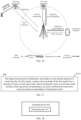
- the communication system includes t a plurality of terminals supporting both the active transmission communication and the backscatter communication.
- the capabilities of these terminals may be different. For example, during the backscatter communication, some terminals use a LNA while others do not use the LAN. Alternatively, even if the different terminals all use a LAN to perform the backscatter communication, their respective LNAs have different capabilities. Alternatively, different terminals have different backscatter losses during the backscatter communication. For example, some terminals have a backscatter loss of 5 dB, while some other terminals have a backscatter of 8 dB. Therefore, the following cases may occur.
- the first-type terminal #1 and the second-type terminal in FIG. 16 have the same distance to the network device, and radio frequency signals (used as carrier signals) received by the two terminals from the network device have the same strength. Since different terminals have different capabilities, if the first-type terminal #1 performs communication using the backscatter mode, the network device is not able to receive the transmitted signal or decode a received signal correctly. In contrast, if the second-type terminal performs communication using the backscatter mode, the network device is able to receive the transmitted signal and decode the received signal correctly.
- the distances between the network device and the same type of terminals e.g., the first-type terminal #1 and the first-type terminal #2 shown in FIG. 16 , are different. If a third-party device can supply power or provide carrier signals (having a high strength value) to the first-type terminal #2 that is further away from the network device, the network device is able to receive the transmitted signal or decode the received signal correctly. In contrast, the first-type terminal #1 that is closer to the network device needs to perform communication using the active transmission mode.
- a coverage area for a zero-power terminal to perform backscatter communication is affected by the receiver sensitivity of the target receiving device, the transmit power of the backscatter signal and the path loss.
- the greater the transmit power of the backscatter signal the greater the communication distance from the zero-power terminal to the target receiving device.
- Embodiment 4 may be combined with any of Embodiment 1, Embodiment 2 and Embodiment 3 described above.
- the first terminal when determining the target transmission mode of the first signal, the first terminal further considers whether a transmit power of a backscatter signal meets the requirement of a target received power of the target receiving device.
- the first signal is transmitted via the backscatter mode; otherwise, the first signal is transmitted via the active transmission mode, or via the active transmission mode and the backscatter mode.
- whether the transmit power of the backscatter signal meets the requirement of the target received power of the target receiving device may be determined based on the transmit power of the backscatter signal, a path loss, and the target received power of the target receiving device.
- the first terminal transmits the first signal using the backscatter mode.
- the first terminal transmits the first signal using the active transmission mode.
- the first terminal transmits the first signal using the active transmission mode and the backscatter mode.
- the first terminal transmits a portion of bits in the information carried by the first signal via the backscatter mode, and transmits the remaining bits in the information carried by the first signal via the active transmission mode.
- the first terminal transmits a portion of bits in the information carried by the first signal via the backscatter mode, and transmits all bits in the information carried by the first signal via the active transmission mode.
- the transmit power of the backscatter signal is considered to meet the first condition; otherwise, the transmit power of the backscatter signal is considered not to meet the first condition.
- the first condition includes that:
- the backscatter mode is determined as the target transmission mode of the first signal, if the backscatter power of the backscatter signal meets the following formula: P Ba ck scatter > P Backscatter , target + PL b or P Ba ck scatter ⁇ P Backscatter , target + PL b , where P Ba cks catter denotes the backscatter power of the backscatter signal, P Backscatter, target denotes the target received power of the target receiving device, and PL b denotes the path loss between the first terminal and the target receiving device.
- the active transmission mode is determined as the target transmission mode of the first signal, if the backscatter power of the backscattered signal meets the following formula: P Ba ck scatter ⁇ P Backscatter , target + PL b or P Ba ck scatter ⁇ P Backscatter , target + PL b , f , where P B ack scatter denotes the backscatter power of the backscatter signal, P Backscatter, target denotes the target received power of the target receiving device, and PL b denotes the path loss between the first terminal and the target receiving device.
- the target received power of the target receiving device is predefined, for example, may be predefined in a protocol. That is to say, the first terminal and the target receiving device may obtain the target received power without information exchange.
- the target received power of the target receiving device is configured by the target receiving device.
- the target receiving device is the network device, and the network device may configure the target received power for the first terminal.
- the target receiving device is the second terminal, and the second terminal may configure the target received power for the first terminal.
- the target received power of the target receiving device is configured by the network device.
- the target receiving device is the network device, and the network device configures the target received power for the first terminal.
- the target receiving device is the second terminal, and the network device configures the target received power for the first terminal.
- the network device may configure the target received power for the second terminal, or the first terminal may indicate the target received power to the second terminal.
- the target receiving device is the network device
- the target received power of the network device P Backscatter,target may refer to the target received power of the network device specific to carrier frequency f and serving cell c, which is denoted as P B ack scatter,t arg et,f ,c .
- the unit of the target received power is dBm.
- the target receiving device is the second terminal
- the target received power of the second terminal P Backscatter,target may refer to the target received power of the second terminal specific to carrier frequency f, which is denoted as P Backscatter,target,f .
- the unit of the target received power is dBm.
- the target received power of the target receiving device is a first received power
- the first received power is a target received power corresponding to the backscatter signal.
- a target received power corresponding to an actively transmitted signal is a second received power, and the second received power is the same as or different from the first received power.
- the actively transmitted signal and the backscatter signal may use the same target received power, or the actively transmitted signal and the backscatter signal may correspond to different target received power.
- the path loss may be generated during the communication between the first terminal and the target receiving device, which refers to a path loss of a signal in a process where the signal is sent from the first terminal until the signal is received by the target receiving device, or a path loss of a signal in the process where the signal is sent from the target receiving device until the signal is received by the first terminal.
- the path loss is a path loss corresponding to backscatter communication, for example, may be a path loss of a signal in a process where the signal is sent from the first terminal via the backscatter mode until the target receiving device receives the signal.
- the path loss may be measured by the target receiving device and indicated by the target receiving device to the first terminal.
- the path loss in a case where the path loss is measured by the first terminal, the path loss may be measured by the auxiliary receiver, or may be measured by the primary receiver (e.g., in the case where the auxiliary receiver and the primary receiver share functional modules).
- the path loss may be determined based on a measurement result of a second signal, and a frequency of the second signal is a first frequency.
- the first frequency may be the same as a frequency of the backscatter communication, or may be different from the frequency of the backscatter communication.
- the path loss of the backscatter communication may be directly calculated according to the measurement result of the second signal.
- the path loss of the backscatter communication may be obtained by processing the measurement result of the second signal.
- the measurement result may be processed based on an adjusting factor or an adjustment, so as to calculate the path loss of the backscatter communication.
- the target receiving device is the network device
- the second signal may be a downlink reference signal, such as a synchronization signal block (SSB), or a channel state information reference signal (CSI-RS).
- SSB synchronization signal block
- CSI-RS channel state information reference signal
- the target receiving device is the second terminal, and the second signal may be a sidelink reference signal, e.g., a sidelink position reference signal (SL-PRS).
- a sidelink reference signal e.g., a sidelink position reference signal (SL-PRS).
- the path loss may be represented by the measurement result of the signal.
- the measurement results may include but are not limited to: a reference signal received power (RSRP), reference signal received quality (RSRQ), a signal to interference plus noise ratio (SINR), and a received signal strength indication (RSSI).
- RSRP reference signal received power
- RSRQ reference signal received quality
- SINR signal to interference plus noise ratio
- RSSI received signal strength indication
- the unit of the path loss may be dBm.
- the target receiving device is the network device
- the path loss PL b between the first terminal and the network device is also denoted as PL b,f,c .
- the first terminal may obtains PL b,f,c through performing measurement, for activated uplink (UL) bandwidth part (BWP) b on carrier frequency f , on a backscatter communication associated downlink reference signal over an activated downlink BWP based on serving cell c.
- UL uplink
- BWP bandwidth part
- the target receiving device is the second terminal, and the path loss PL b between the first terminal and the second terminal is also denoted as PL b,f .
- the first terminal may obtain the path loss PL b,f through performing measurement, for activated sidelink (SL) BWP b at carrier frequency f , on a backscatter communication associated sidelink reference signal over an activated sidelink BWP.
- SL sidelink
- the transmit power of the backscatter signal may refer to a power of the backscatter signal finally transmitted by the first terminal when performing backscatter communication.
- the transmit power of the backscatter signal may be less than, equal to, or greater than an incident power of the carrier signal.
- the first terminal may perform backscatter directly based on the carrier signal when performing backscatter communication. Since the backscatter communication will cause a certain loss, the transmit power of the backscatter signal is usually less than the incident power of the carrier signal.
- the first terminal may further amplify the backscatter signal when performing backscatter communication.
- the transmit power of the backscatter signal may be greater than or equal to the incident power of the carrier signal.
- the transmit power of the backscatter signal is related to factors such as the power of the carrier signal, the gain of the first terminal, and the loss caused by the backscatter communication.
- the transmit power of the backscatter signal is determined according to the power of the carrier signal and a first gain.
- the first gain is a gain of the transmit power of the backscatter signal relative to the power of the carrier signal.
- the sum of the power of the carrier signal and the first gain may be determined as the transmit power of the backscatter signal.
- the source of the carrier signal is not limited in the embodiments of the present application.
- the carrier signal may be a dedicated carrier signal.
- other signals may be used as the carrier signal, such as a radio signal in the ambient, or a signal carrying the scheduling information of the first signal.
- the dedicated carrier signal may be provided by the network device, or provided by the target receiving device, or provided by a third-party device.
- the first gain includes at least one of the following: a loss UE B ack scatter, loss caused by backscatter communication performed by the first terminal, an antenna gain UE Gain, antenma of the first terminal, a low noise amplifier (LNA) gain UE Gain,LNA of the first terminal, a power-storage related gain UE Gain,P ower of the first terminal, or other gains UE Gain ,other of the first terminal.
- a loss UE B ack scatter loss caused by backscatter communication performed by the first terminal
- an antenna gain UE Gain antenma of the first terminal
- a low noise amplifier (LNA) gain UE Gain,LNA of the first terminal a power-storage related gain UE Gain,P ower of the first terminal, or other gains UE Gain ,other of the first terminal.
- LNA low noise amplifier
- the loss UE B ack scatter, loss caused by backscatter communication performed by the first terminal includes, but is not limited to, the loss caused by the backscatter communication itself, and optionally, may further include a loss caused by other circuit hardware during the backscatter communication.
- UE Gain,P ower may include a power gain obtained by the first terminal through the battery, power storing, or other ambient power harvesting manners.
- UE Gain may refer to other gains except those mentioned above.
- the LNA gain of the first terminal may be understood as a power amplification gain of the first terminal, i.e., a gain derived from amplifying process performed by the first terminal on the backscatter signal.
- the gain may be caused by an LNA, a PA, or a device with a power amplification function such as a transistor, or a tunnel diode, which is not limited in the present application.
- the transmit power of the backscatter signal is determined according to the power of the carrier signal, a loss caused by the backscatter communication performed by first terminal, and the second gain.
- the loss caused by backscatter communication performed by the first terminal may include, but is not limited to, the loss caused by the backscatter communication itself, and optionally, may further include the loss caused by other circuit hardware during the backscatter communication.
- the second gain is a gain derived from backscatter communication performed by the first terminal.
- the second gain includes at least one of the following:
- the first terminal supporting dual-mode transmission when the first terminal supporting dual-mode transmission is going to transmit a signal, the first terminal selects the target transmission mode according to the time domain feature of the transmitting time of the signal to be transmitted, which is beneficial to balancing terminal power saving and reliable transmission of signals.
- a wireless communication method according to the embodiments of the present application is described above in detail from the perspective of the first terminal.
- FIG. 17 a wireless communication method according to another embodiment of the present application will be described below in detail from the perspective of the target receiving device. It should be understood that the description related to the target receiving device side corresponds to the description related to the first terminal side, and similar descriptions can be found above, which will not be repeated here for brevity.
- FIG. 17 is a schematic flow chart of a wireless communication method 300 according to another embodiment of the present application. As shown in FIG. 11 , the method 300 includes the following contents.
- the target receiving device determines a target receiving mode of a first signal from a plurality of types of receiving modes according to a time domain feature of a receiving time of the first signal; where the plurality of types of receiving modes include a receiving mode corresponding to an active transmission mode and a receiving mode corresponding to a backscatter mode, and the target receiving device is a receiving device of the first signal.
- the target receiving device includes a primary receiver (also called the conventional receiver) and an auxiliary receiver.
- the power consumption of the primary receiver is higher than that of the auxiliary receiver, and/or the complexity of the primary receiver is higher than that of the auxiliary receiver.
- the primary receiver may be used to receive a signal transmitted through the active transmission mode.
- the primary receiver may have a relative high information processing capability, such as supporting a large bandwidth (e.g., 100 MHz), or receiving and processing high-rate information.
- a relative high information processing capability such as supporting a large bandwidth (e.g., 100 MHz), or receiving and processing high-rate information.
- the auxiliary receiver may be used to receive the signal transmitted through the backscatter mode.
- the auxiliary receiver may have a relative low capability information processing capability, such as only supporting a narrowband, or receiving and processing low-rate information.
- the primary receiver and the auxiliary receiver may be independent modules; alternatively, the primary receiver and the auxiliary receiver may include different functional modules of the receiver of the target receiving device; alternatively, the primary receiver and the auxiliary receiver may share different functional modules.
- the target receiving device includes only one receiver, which is used to receive signals transmitted through the active transmission mode and signals transmitted through the backscatter mode.
- the main receiver and the auxiliary receiver are the same receiver.
- the receiving mode corresponding to the active transmission mode may refer to a demodulation manner corresponding to a high-order modulation manner, or in other words, a demodulation manner corresponding to a high-complexity modulation manner.
- the demodulation manner corresponding to the high-order modulation manner may be a processing such as an OFDM demodulation, or channel estimation.
- the receiving mode corresponding to the backscatter mode may refer to a demodulation manner corresponding to a low-order modulation manner, or in other words, a demodulation mode corresponding to a low-complexity modulation manner.
- the demodulation manner corresponding to the low-order modulation manner may be ASK demodulation, PSK demodulation, or OOK demodulation.
- that the target receiving device receives the first signal using the receiving mode corresponding to the active transmission mode may include that: the target receiving device receives the first signal through the primary receiver.
- that the target receiving device receives the first signal using the receiving mode corresponding to the backscatter mode may include that: the target receiving device receives the first signal through the auxiliary receiver.
- the time domain feature of the receiving time of the first signal may include a time domain resource type corresponding to the receiving time of the first signal.
- time domain resources for backscatter communication and time domain resources for active transmission communication are distributed based on a first pattern.
- the first pattern is predefined; or the first pattern is configured by a network device.
- the first pattern is periodic.
- a position of the first pattern is fixed or variable.
- a reference for determining the position of the first pattern is a first time domain position.
- the start position of the first pattern is the first time domain position; or the start position of the first pattern is a second time domain position, and the second time domain position has a first offset relative to the first time domain position.
- the first time domain position is a time domain position where the scheduling information of the first signal is located.
- the method 300 further includes: transmitting, by the target receiving device, first indication information to the first terminal; where the first indication information is used for indicating the first time domain position.
- the first indication information is carried in the scheduling information of the first signal, or may be carried in other information.
- the first pattern is represented by a first bitmap
- the first bitmap includes a plurality of bit groups, each bit group includes one or more bits, each bit group corresponds to N time units, and a value of each bit group is used to indicate the resource type of corresponding N time units; where N is a positive integer.
- each bit group is used to indicate that the corresponding N time units are time domain resources for backscatter communication, or time domain resources for active transmission communication, or flexible time domain resources; or the value of each bit group is used to indicate whether the corresponding N time units are time domain resources for backscatter communication or time domain resources for active transmission communication.
- S310 may include: determining the target receiving mode of the first signal according to the time domain resource type corresponding to the receiving time of the first signal in the first pattern.
- determining the target receiving mode of the first signal according to the time domain resource type corresponding to the receiving time of the first signal in the first pattern includes:
- the method 300 further includes:
- the method 300 further includes:
- time domain resources for backscatter communication and time domain resources for active transmission communication are determined based on a switching time of transmission modes, and the switching time of transmission modes includes a switching time from the active transmission mode to the backscatter mode and/or a switching time from the backscatter mode to the active transmission mode.
- that the terminal device determines the target receiving mode of the first signal from the plurality of types of receiving modes according to the time domain feature of the receiving time of the first signal includes:
- the switching time is periodic.
- a position of the switching time is fixed or variable.
- a reference for determining the position of the switching time is a third time domain position.
- a start position of the switching time is the third time domain position; or the start position of the switching time is a fourth time domain position, and the fourth time domain position has a second offset relative to the third time domain position.
- the third time domain position is a time domain position where scheduling information of the first signal is located.
- the method further includes: transmitting, by the target receiving device, second indication information to the first terminal; where the second indication information is used for indicating the third time domain position.
- the second indication information is carried in the scheduling information of the first signal.
- time domain resources for backscatter communication and time domain resources for active transmission communication are determined based on a time window.
- the time window corresponds to a first transmission mode, which is the active transmission mode or the backscatter mode.
- the first transmission mode is the backscatter mode, time domain resources within the time window are used for backscatter communication, and time domain resources outside the time window are used for active transmission communication; or the first transmission mode is the backscatter mode, time domain resources within the time window are used by the terminal device to initiate backscatter communication, and time domain resources outside the time window are used for active transmission communication and/or the backscatter communication.
- the first transmission mode is the active transmission mode, the time domain resources within the time window are used for active transmission communication, and the time domain resources outside the time window are used for backscatter communication; or the first transmission mode is the active transmission mode, the time domain resources within the time window are used by the terminal device to initiate active transmission communication, and the time domain resources outside the time window are used for active transmission communication and/or backscatter communication.
- the time window is predefined; or the time window is configured by the network device.
- the time window is periodic.
- a position of the time window is fixed or variable.
- the position of the time window is determined according to first information, and the first information includes at least one of the following: a time length of the time window, a start position of the time window, an end position of the time window, an offset of the start position of the time window relative to a reference time domain position, an offset of the end position of the time window relative to the reference time domain position, period information of the time window, or a ratio of the time length of the time window to a period of the time window.
- that the target receiving device determines the target receiving mode of the first signal from a plurality of types of receiving modes according to the time domain feature of the receiving time of the first signal includes:
- FIG. 18 shows a schematic block diagram of a terminal device 400 according to the embodiments of the present application.
- the terminal device 400 includes: a processing unit 410, configured to determine a target transmission mode of the first signal from a plurality of types of transmission modes according to a time domain feature of a transmitting time of the first signal; where the plurality of types of transmission modes include an active transmission mode and a backscatter mode.
- the time domain feature of the transmitting time of the first signal includes a time domain resource type corresponding to the transmitting time of the first signal.
- time domain resources for the backscatter communication and time domain resources for the active transmission communication are distributed based on a first pattern.
- the first pattern is predefined, or
- the first pattern is periodic.
- a position of the first pattern is fixed or variable.
- a reference for determining the position of the first pattern is a first time domain position.
- the start position of the first pattern is the first time domain position; or the start position of the first pattern is a second time domain position, and the second time domain position has a first offset relative to the first time domain position.
- the first offset is predefined, or
- the first time domain position is a time domain position at which the terminal device receives scheduling information of the first signal; or the first time domain position is a time domain position indicated by the target receiving device of the first signal or the network device.
- the first pattern is represented by a first bitmap
- the first bitmap includes a plurality of bit groups, each bit group includes one or more bits, each bit group corresponds to N time units, and a value of each bit group is used to indicate a resource type of corresponding N time units; where N is a positive integer.
- each bit group is used to indicate that the corresponding N time units are time domain resources for backscatter communication, or time domain resources for active transmission communication, or flexible time domain resources; or the value of each bit group is used to indicate whether the corresponding N time units are time domain resources for backscatter communication or time domain resources for active transmission communication.
- the processing unit 410 is further configured to: determine the target transmission mode of the first signal according to the time domain resource type corresponding to the transmitting time of the first signal in the first pattern.
- processing unit 410 is further configured to:
- the terminal device further includes:
- the terminal device further includes:
- the processing unit 410 is further configured to: determine the target transmission mode of the first signal according to the time domain resource type corresponding to the transmitting time of the first signal in the first pattern and a size of remaining time domain resources with the (same) time domain resource type after the transmitting time.
- processing unit 410 is further configured to:
- processing unit 410 is further configured to:
- processing unit 410 is further configured to:
- time domain resources for backscatter communication and time domain resources for active transmission communication are determined based on a switching time of transmission modes.
- the switching time of transmission modes includes a switching time from the active transmission mode to the backscatter mode and/or a switching time from the backscatter mode to the active transmission mode.
- processing unit 410 is further configured to:
- the switching time is predefined; or
- the switching time is periodic.
- a position of the switching time is fixed or variable.
- a reference for determining the position of the switching time is a third time domain position.
- the start position of the switching time is the third time domain position; or the start position of the switching time is a fourth time domain position, and the fourth time domain position has a second offset relative to the third time domain position.
- the second offset is predefined; or
- the third time domain position is a time domain position at which the terminal device receives scheduling information of the first signal; or the third time domain position is a time domain position indicated by the target receiving device of the first signal or the network device.
- time domain resources for backscatter communication and time domain resources for active transmission communication are determined based on a time window.
- the time window corresponds to a first transmission mode, and the first transmission mode is the active transmission mode or the backscatter mode.
- the first transmission mode is the backscatter mode, time domain resources within the time window are used for backscatter communication, and time domain resources outside the time window are used for active transmission communication; or the first transmission mode is the backscatter mode, time domain resources within the time window are used by the terminal device to initiate the backscatter communication, and time domain resources outside the time window are used for the active transmission communication and/or the backscatter communication.
- the first transmission mode is the active transmission mode, time domain resources within the time window are used for the active transmission communication, and time domain resources outside the time window are used for the backscatter communication; or the first transmission mode is the active transmission mode, time domain resources within the time window are used by the terminal device to initiate the active transmission communication, and time domain resources outside the time window are used for the active transmission communication and/or the backscatter communication.
- the time window is predefined; or
- the time window is periodic.
- a position of the time window is fixed or variable.
- the position of the time window is determined according to first information, and the first information includes at least one of the following: a time length of the time window, a start position of the time window, an end position of the time window, an offset of the start position of the time window relative to a reference time domain position, an offset of the end position of the time window relative to the reference time domain position, period information of the time window, or a ratio of the time length of the time window to a period of the time window.
- the first information is predefined; or
- processing unit 410 is further configured to:
- processing unit 410 is further configured to:
- the first condition includes that:
- the transmit power of the backscatter signal is determined according to a power of the carrier signal and a first gain, and the first gain is a gain of the transmit power of the backscatter signal relative to the power of the carrier signal; or the transmit power of the backscatter signal is determined according to the power of the carrier signal, the loss caused by the backscatter communication performed by the terminal device, and a second gain, and the second gain is a gain derived from backscatter communication performed by the terminal device.
- the first gain includes at least one of the following: the loss caused by the backscatter communication performed by the terminal device, an antenna gain of the terminal device, a low noise amplifier (LNA) gain of the terminal device, or a power-storage related gain of the terminal device.
- LNA low noise amplifier
- the second gain includes at least one of the following: the antenna gain of the terminal device, the LNA gain of the terminal device, or the power-storage related gain of the terminal device.
- the carrier signal is a signal used to carry the scheduling information of the first signal; or the carrier signal is a dedicated carrier signal.
- the transmitting time of the first signal is indicated by the network device or determined by the terminal device.
- the terminal device includes a first transmitter and a second transmitter.
- the first transmitter supports transmitting the signal using the active transmission mode
- the second transmitter supports transmitting the signal using the backscatter transmission mode.
- the communication unit may be a communication interface or a transceiver, or an input/output interface of a communication chip or a system on chip.
- the processing unit mentioned above may include one or more processors.
- terminal device 400 may correspond to the first terminal in the methods embodiment of the present application, and the above-mentioned and other operations and/or functions of each unit in the terminal device 400 are respectively for implementing the corresponding processes of the first terminal in the method shown in FIGS. 6 to 17 , which will not be repeated here for the sake of brevity.
- FIG. 19 shows a schematic block diagram of a communication device 500 according to the embodiments of the present application.
- the communication device 500 includes: a processing unit 510, configured to determine a target receiving mode of the first signal from a plurality of types of receiving modes according to a time domain feature of a receiving time of the first signal; where the plurality of types of receiving modes include a receiving mode corresponding to an active transmission mode and a receiving mode corresponding to a backscatter mode.
- the time domain feature of the transmitting time of the first signal includes a time domain resource type corresponding to the transmitting time of the first signal.
- time domain resources for backscatter communication and time domain resources for active transmission communication are distributed based on a first pattern.
- the first pattern is predefined; or the first pattern is configured by a network device.
- the first pattern is periodic.
- a position of the first pattern is fixed or variable.
- a reference for determining the position of the first pattern is a first time domain position.
- the start position of the first pattern is the first time domain position; or the start position of the first pattern is a second time domain position, and the second time domain position has a first offset relative to the first time domain position.
- the first time domain position is a time domain position where scheduling information of the first signal is located.
- the communication device further includes: a communication unit, configured to transmit first indication information to a terminal device; where the first indication information is used for indicating the first time domain position.
- the first indication information is carried in the scheduling information of the first signal.
- the first pattern is represented by a first bitmap
- the first bitmap includes a plurality of bit groups, each bit group includes one or more bits, each bit group corresponds to N time units, and a value of each bit group is used to indicate the resource type of the corresponding N time units; where N is a positive integer.
- each bit group is used to indicate that the corresponding N time units are time domain resources for the backscatter communication, or time domain resources for the active transmission communication, or flexible time domain resources; or the value of each bit group is used to indicate whether the corresponding N time units are time domain resources for the backscatter communication or time domain resources for the active transmission communication.
- the processing unit 510 is further configured to: determine the target receiving mode of the first signal according to the time domain resource type corresponding to the receiving time of the first signal in the first pattern.
- processing unit 510 is further configured to:
- the communication device further includes:
- the communication device further includes:
- time domain resources for backscatter communication and time domain resources for active transmission communication are determined based on the switching time of transmission modes, where the switching time of transmission modes includes the switching time from the active transmission mode to the backscatter mode and/or the switching time from the backscatter mode to the active transmission mode.
- processing unit 510 is further configured to:
- the switching time is periodic.
- a position of the switching time is fixed or variable.
- a reference for determining the position of the switching time is a third time domain position.
- a start position of the switching time is the third time domain position; or the start position of the switching time is a fourth time domain position, and the fourth time domain position has a second offset relative to the third time domain position.
- the third time domain position is a time domain position where the scheduling information of the first signal is located.
- the communication device further includes: a communication unit, configured to transmit second indication information to the first terminal; where the second indication information is used for indicating the third time domain position.
- the second indication information is carried in scheduling information of the first signal.
- time domain resources for backscatter communication and time domain resources for active transmission communication are determined based on a time window.
- the time window corresponds to a first transmission mode, which is the active transmission mode or the backscatter mode.
- the first transmission mode is the backscatter mode, time domain resources within the time window are used for the backscatter communication, and time domain resources outside the time window are used for the active transmission communication; or the first transmission mode is the backscatter mode, time domain resources within the time window are used by the first terminal to initiate the backscatter communication, and time domain resources outside the time window are used for the active transmission communication and/or the backscatter communication.
- the first transmission mode is the active transmission mode, time domain resources within the time window are used for the active transmission communication, and time domain resources outside the time window are used for the backscatter communication; or the first transmission mode is the active transmission mode, time domain resources within the time window are used by the first terminal to initiate the active transmission communication, and time domain resources outside the time window are used for the active transmission communication and/or the backscatter communication.
- the time window is predefined; or the time window is configured by the network device.
- the time window is periodic.
- a position of the time window is fixed or variable.
- the position of the time window is determined according to first information, and the first information includes at least one of the following: a time length of the time window, a start position of the time window, an end position of the time window, an offset of the start position of the time window relative to the reference time domain position, an offset of the end position of the time window relative to a reference time domain position, period information of the time window, or a ratio of the time length of the time window to a period of the time window.
- processing unit 510 is further configured to:
- the communication device 500 may correspond to the target receiving device in the method embodiments of the present application, and the above-mentioned and other operations and/or functions of each unit in the communication device 500 are respectively for implementing the corresponding processes of the target receiving device in the method shown in FIGS. 6 to 17 , which will not be repeated here for the sake of brevity.
- FIG. 20 is a schematic structural diagram of a communication device 600 according to embodiments of the present application.
- the communication device 600 shown in FIG. 20 includes a processor 610.
- the processor 610 invokes and runs a computer program from a memory to implement the methods in the embodiments of the present application.
- the communication device 600 may further include a memory 620.
- the processor 610 invokes and runs a computer program from the memory 620 to implement the methods in the embodiments of the present application.
- the memory 620 may be a separate device independent of the processor 610 or may be integrated into the processor 610.
- the communication device 600 may further include a transceiver 630, and the processor 610 may control the transceiver 630 to communicate with other devices. Specifically, the processor 610 may control the transceiver 630 to transmit information or data to other devices, or receive information or data transmitted by other devices.
- the transceiver 630 may include a transmitter and a receiver.
- the transceiver 630 may further include antenna(s), and the number of antenna(s) may be one or more.
- the communication device 600 may specifically be the target receiving device in the embodiments of the present application, and implement corresponding processes implemented by the target receiving device in various methods in the embodiments of the present application, which will not be repeated here for brevity.
- the communication device 600 may specifically be the first terminal in the embodiments of the present application, and implement corresponding processes implemented by the first terminal in various methods in the embodiments of the present application, which will not be repeated here for brevity.
- FIG. 21 is a schematic structural diagram of a chip according to embodiments of the present application.
- the chip 700 shown in FIG. 21 includes a processor 710, and the processor 710 invokes and runs a computer program from a memory to implement the methods in the embodiments of the present application.
- the chip 700 may further include a memory 720.
- the processor 710 invokes and runs a computer program from the memory 720 to implement the methods in the embodiments of the present application.
- the memory 720 may be a separate device independent of the processor 710 or may be integrated into the processor 710.
- the chip 700 may further include an input interface 730.
- the processor 710 may control the input interface 730 to communicate with other devices or chips. Specifically, the processor 710 may control the input interface 730 to obtain information or data transmitted by other devices or chips.
- the chip 700 may further include an output interface 740.
- the processor 710 may control the output interface 740 to communicate with other devices or chips.
- the processor 710 may control the output interface 740 to output information or data to other devices or chips.
- the chip may be applied to the target receiving device in the embodiments of the present application, and the chip may implement corresponding processes implemented by the target receiving device in various methods in the embodiments of the present application, which will not be repeated here for brevity.
- the chip may be applied to the first terminal in the embodiments of the present application, and the chip may implement corresponding processes implemented by the first terminal in various methods in the embodiments of the present application, which will not be repeated here for brevity.
- the chip mentioned in the embodiments of the present application may be referred to as a system-level chip, a system chip, a chip system or a system-on-chip.
- FIG. 22 is a schematic block diagram of a communication system 900 according to embodiments of the present application. As shown in FIG. 22 , the communication system 900 includes a first terminal 910 and a second device 920.
- the first terminal 910 may be configured to implement the corresponding functions implemented by the first terminal in the above methods
- the target receiving device 920 may be configured to implement the corresponding functions implemented by the target receiving device in the above methods, which will not be repeated here for brevity.
- the processor in the embodiments of the present application may be an integrated circuit chip with a capability for processing signals.
- various steps of the above method embodiments may be completed by an integrated logic circuit of hardware in a processor or instructions in a software form.
- the above processor may be a general-purpose processor, a digital signal processor (DSP), an application specific integrated circuit (ASIC), a field programmable gate array (FPGA) or another programmable logic device, a discrete gate or transistor logic device, or a discrete hardware component.
- the processor may implement various methods, steps and logical block diagrams disclosed in the embodiments of the present application.
- the general-purpose processor may be a microprocessor, or the processor may be any conventional processor.
- the steps of the methods disclosed in combination with the embodiments of the present application may be directly embodied by execution of a hardware decoding processor, or by execution of a combination of hardware and software modules in a decoding processor.
- the software module may be located in a storage medium commonly used in the art, such as a random access memory, a flash memory, a read-only memory, a programmable read-only memory or an electrically erasable programmable memory, or a register.
- the storage medium is located in a memory (memories), and the processor reads information in the memory (memories) and completes the steps of the above methods in combination with hardware of the processor.
- the memory in the embodiments of the present application may be a volatile memory or a non-volatile memory, or the memories may include both volatile and non-volatile memories.
- the non-volatile memory may be a read-only memory (ROM), a programmable read-only memory (Programmable ROM, PROM), an erasable programmable read-only memory (Erasable PROM, EPROM), an electrically erasable programmable read-only memory (Electrically EPROM, EEPROM) or a flash memory.
- the volatile memory may be a random access memory (RAM), which is used as an external cache.
- RAMs such as a static random access memory (Static RAM, SRAM), a dynamic random access memory (Dynamic RAM, DRAM), a synchronous dynamic random access memory (Synchronous DRAM, SDRAM), a double data rate synchronous dynamic random access memory (Double Data Rate SDRAM, DDR SDRAM), an enhanced synchronous dynamic random access memory (Enhanced SDRAM, ESDRAM), a synchronous link dynamic random access memory (Synchlink DRAM, SLDRAM), and a direct rambus random access memory (Direct Rambus RAM, DR RAM).
- static random access memory Static RAM, SRAM
- DRAM dynamic random access memory
- DRAM synchronous dynamic random access memory
- SDRAM double data rate synchronous dynamic random access memory
- Enhanced SDRAM, ESDRAM enhanced synchronous dynamic random access memory
- Synchrobus RAM synchronous link dynamic random access memory
- Direct Rambus RAM Direct Rambus RAM
- the memory in embodiments of the present application may be a static RAM (SRAM), a dynamic RAM (DRAM), a synchronous DRAM (SDRAM), a double data rate SDRAM (DDR SDRAM), an enhanced SDRAM (ESDRAM), a synch link DRAM (SLDRAM), or a direct rambus RAM (DR RAM). That is, the memories in the embodiments of the present application are intended to include, but are not limited to, these and any other suitable types of memories.
- SRAM static RAM
- DRAM dynamic RAM
- SDRAM synchronous DRAM
- DDR SDRAM double data rate SDRAM
- ESDRAM enhanced SDRAM
- SLDRAM synch link DRAM
- DR RAM direct rambus RAM
- the embodiments of the present application further provide a computer-readable storage medium for storing a computer program.
- the computer-readable storage medium may be applied to the first terminal in the embodiments of the present application, and the computer program enables a computer to perform the corresponding processes implemented by the first terminal in the various methods in the embodiments of the present application, which will not be repeated here for brevity.
- the computer-readable storage medium may be applied to the target receiving device in the embodiments of the present application, and the computer program enables a computer to perform the corresponding processes implemented by the target receiving device in various methods in the embodiments of the present application, which will not be repeated here for brevity.
- the embodiments of the present application further provide a computer program product including computer program instructions.
- the computer program product may be applied to the first terminal in the embodiments of the present application, and the computer program instructions enable a computer to perform the corresponding processes implemented by the first terminal in the various methods in the embodiments of the present application, which will not be repeated here for brevity.
- the computer program product may be applied to the target receiving device in the embodiments of the present application, and the computer program instructions enable a computer to perform the corresponding processes implemented by the target receiving device in various methods in the embodiments of the present application, which will not be repeated here for brevity.
- the embodiments of the present application further provide a computer program.
- the computer program may be applied to the first terminal in the embodiments of the present application, and the computer program, when run on a computer, enables the computer to perform the corresponding processes implemented by the first terminal in various methods in the embodiments of the present application, which will not be repeated here for brevity.
- the computer program may be applied to the target receiving device in the embodiments of the present application, and the computer program, when run on a computer, enables the computer to perform the corresponding processes implemented by the target receiving device in various methods in the embodiments of the present application, which will not be repeated here for brevity.
- the units described as separate components may be or may be not physically separated, and the components shown as units may be or may be not physical units (that is, they may be located in one place or may be distributed on multiple network units). Some or all of units may be selected according to actual needs to achieve purposes of solutions of the embodiments.
- various functional units in various embodiments of the present application may be integrated in one processing unit, or various units may be physically present separately, or two or more units may be integrated in one unit.
- the functions, if implemented in a form of software functional units and sold or used as an independent product, may be stored in a computer-readable storage medium.
- the technical solutions of the present application may be embodied in the form of a software product in essence, or a part of the technical solutions that contributes to the prior art or a part of the technical solutions may be embodied in the form of a software product.
- the computer software product is stored in one storage medium including several instructions for enabling a computer device (which may be a personal computer, a server, or a network device) to perform all or some of the steps of the methods described in various embodiments of the present application.
- the aforementioned storage medium includes a U disk, a mobile hard disk, a read-only memory (ROM), a random access memory (RAM), a magnetic disk, an optical disk, or any medium capable of storing program codes.
Landscapes
- Engineering & Computer Science (AREA)
- Signal Processing (AREA)
- Computer Networks & Wireless Communication (AREA)
- Health & Medical Sciences (AREA)
- Computing Systems (AREA)
- General Health & Medical Sciences (AREA)
- Medical Informatics (AREA)
- Mobile Radio Communication Systems (AREA)
Applications Claiming Priority (1)
| Application Number | Priority Date | Filing Date | Title |
|---|---|---|---|
| PCT/CN2022/114029 WO2024040402A1 (zh) | 2022-08-22 | 2022-08-22 | 无线通信的方法和设备 |
Publications (1)
| Publication Number | Publication Date |
|---|---|
| EP4580225A1 true EP4580225A1 (de) | 2025-07-02 |
Family
ID=90012109
Family Applications (1)
| Application Number | Title | Priority Date | Filing Date |
|---|---|---|---|
| EP22955951.3A Pending EP4580225A1 (de) | 2022-08-22 | 2022-08-22 | Verfahren und vorrichtung zur drahtlosen kommunikation |
Country Status (4)
| Country | Link |
|---|---|
| US (1) | US20250142541A1 (de) |
| EP (1) | EP4580225A1 (de) |
| CN (1) | CN119054309A (de) |
| WO (1) | WO2024040402A1 (de) |
Family Cites Families (7)
| Publication number | Priority date | Publication date | Assignee | Title |
|---|---|---|---|---|
| CA2307361C (en) * | 2000-05-01 | 2008-04-08 | Mark Iv Industries Limited | Multiple protocol transponder |
| US7215976B2 (en) * | 2001-11-30 | 2007-05-08 | Symbol Technologies, Inc. | RFID device, system and method of operation including a hybrid backscatter-based RFID tag protocol compatible with RFID, bluetooth and/or IEEE 802.11x infrastructure |
| CN111343216B (zh) * | 2018-12-18 | 2022-09-20 | 深圳先进技术研究院 | 物联网数据传输方法、装置、终端设备及可读存储介质 |
| WO2021253307A1 (en) * | 2020-06-18 | 2021-12-23 | Qualcomm Incorporated | Downlink control information indication for passive sensing |
| BR112023015762A2 (pt) * | 2021-02-08 | 2023-11-07 | Interdigital Patent Holdings Inc | Método implementado em uma primeira unidade de transmissão/recepção sem fio, e, primeira unidade de transmissão/recepção sem fio |
| CN113922937B (zh) * | 2021-09-01 | 2023-04-28 | 中国信息通信研究院 | 一种无线信号传输方法和设备 |
| CN114205868B (zh) * | 2021-11-29 | 2024-05-14 | 华中科技大学 | 主被动混合通信方法、系统及电子设备 |
-
2022
- 2022-08-22 CN CN202280095300.5A patent/CN119054309A/zh active Pending
- 2022-08-22 EP EP22955951.3A patent/EP4580225A1/de active Pending
- 2022-08-22 WO PCT/CN2022/114029 patent/WO2024040402A1/zh not_active Ceased
-
2024
- 2024-12-26 US US19/002,517 patent/US20250142541A1/en active Pending
Also Published As
| Publication number | Publication date |
|---|---|
| CN119054309A (zh) | 2024-11-29 |
| US20250142541A1 (en) | 2025-05-01 |
| WO2024040402A1 (zh) | 2024-02-29 |
Similar Documents
| Publication | Publication Date | Title |
|---|---|---|
| US20240179639A1 (en) | Wireless communication method and device | |
| WO2023159495A1 (zh) | 通信方法、终端设备、网络设备、芯片和存储介质 | |
| US20240137194A1 (en) | Method and device for wireless communication | |
| US20250126572A1 (en) | Wireless communication method and device | |
| US20240373375A1 (en) | Wireless communication method, terminal device, and energy supply node | |
| US20250247837A1 (en) | Wireless communication method and device | |
| US20250274901A1 (en) | Wireless communication method and device | |
| US20250126007A1 (en) | Wireless communication method and device | |
| US20250142471A1 (en) | Method for wireless communication, terminal device, and chip | |
| US20250016604A1 (en) | Method and device for wireless communication | |
| US20250030519A1 (en) | Wireless communication method and device | |
| US20250096958A1 (en) | Wireless communication method and device | |
| US20240414767A1 (en) | Channel listening method and communication device | |
| US20240349257A1 (en) | Method for data transmission and communication device | |
| WO2023000175A1 (zh) | 无线通信方法、第一设备和第二设备 | |
| EP4580225A1 (de) | Verfahren und vorrichtung zur drahtlosen kommunikation | |
| US20250351087A1 (en) | Wireless communication methods, network devices and terminal devices | |
| US20250274254A1 (en) | Wireless communication method and device | |
| US20250365662A1 (en) | Method for wireless communication, network device, and ambient power-enabled (amp) device | |
| US20250267569A1 (en) | Wireless communication method and device | |
| CN120826933A (zh) | 无线通信的方法、环境能amp设备和网络设备 | |
| CN120898468A (zh) | 无线通信的方法、环境能amp设备和网络设备 |
Legal Events
| Date | Code | Title | Description |
|---|---|---|---|
| STAA | Information on the status of an ep patent application or granted ep patent |
Free format text: STATUS: THE INTERNATIONAL PUBLICATION HAS BEEN MADE |
|
| PUAI | Public reference made under article 153(3) epc to a published international application that has entered the european phase |
Free format text: ORIGINAL CODE: 0009012 |
|
| STAA | Information on the status of an ep patent application or granted ep patent |
Free format text: STATUS: REQUEST FOR EXAMINATION WAS MADE |
|
| 17P | Request for examination filed |
Effective date: 20241223 |
|
| AK | Designated contracting states |
Kind code of ref document: A1 Designated state(s): AL AT BE BG CH CY CZ DE DK EE ES FI FR GB GR HR HU IE IS IT LI LT LU LV MC MK MT NL NO PL PT RO RS SE SI SK SM TR |
|
| DAV | Request for validation of the european patent (deleted) | ||
| DAX | Request for extension of the european patent (deleted) |