EP4580190A2 - Verfahren zur verarbeitung eines videosignals unter verwendung von subblockbasierter bewegungskompensation - Google Patents
Verfahren zur verarbeitung eines videosignals unter verwendung von subblockbasierter bewegungskompensation Download PDFInfo
- Publication number
- EP4580190A2 EP4580190A2 EP25165249.1A EP25165249A EP4580190A2 EP 4580190 A2 EP4580190 A2 EP 4580190A2 EP 25165249 A EP25165249 A EP 25165249A EP 4580190 A2 EP4580190 A2 EP 4580190A2
- Authority
- EP
- European Patent Office
- Prior art keywords
- current block
- subblock
- merge
- motion vector
- flag
- Prior art date
- Legal status (The legal status is an assumption and is not a legal conclusion. Google has not performed a legal analysis and makes no representation as to the accuracy of the status listed.)
- Pending
Links
Images


Classifications
-
- H—ELECTRICITY
- H04—ELECTRIC COMMUNICATION TECHNIQUE
- H04N—PICTORIAL COMMUNICATION, e.g. TELEVISION
- H04N19/00—Methods or arrangements for coding, decoding, compressing or decompressing digital video signals
- H04N19/50—Methods or arrangements for coding, decoding, compressing or decompressing digital video signals using predictive coding
- H04N19/503—Methods or arrangements for coding, decoding, compressing or decompressing digital video signals using predictive coding involving temporal prediction
- H04N19/51—Motion estimation or motion compensation
- H04N19/523—Motion estimation or motion compensation with sub-pixel accuracy
-
- H—ELECTRICITY
- H04—ELECTRIC COMMUNICATION TECHNIQUE
- H04N—PICTORIAL COMMUNICATION, e.g. TELEVISION
- H04N19/00—Methods or arrangements for coding, decoding, compressing or decompressing digital video signals
- H04N19/10—Methods or arrangements for coding, decoding, compressing or decompressing digital video signals using adaptive coding
- H04N19/102—Methods or arrangements for coding, decoding, compressing or decompressing digital video signals using adaptive coding characterised by the element, parameter or selection affected or controlled by the adaptive coding
- H04N19/103—Selection of coding mode or of prediction mode
- H04N19/105—Selection of the reference unit for prediction within a chosen coding or prediction mode, e.g. adaptive choice of position and number of pixels used for prediction
-
- H—ELECTRICITY
- H04—ELECTRIC COMMUNICATION TECHNIQUE
- H04N—PICTORIAL COMMUNICATION, e.g. TELEVISION
- H04N19/00—Methods or arrangements for coding, decoding, compressing or decompressing digital video signals
- H04N19/10—Methods or arrangements for coding, decoding, compressing or decompressing digital video signals using adaptive coding
- H04N19/102—Methods or arrangements for coding, decoding, compressing or decompressing digital video signals using adaptive coding characterised by the element, parameter or selection affected or controlled by the adaptive coding
- H04N19/103—Selection of coding mode or of prediction mode
- H04N19/11—Selection of coding mode or of prediction mode among a plurality of spatial predictive coding modes
-
- H—ELECTRICITY
- H04—ELECTRIC COMMUNICATION TECHNIQUE
- H04N—PICTORIAL COMMUNICATION, e.g. TELEVISION
- H04N19/00—Methods or arrangements for coding, decoding, compressing or decompressing digital video signals
- H04N19/10—Methods or arrangements for coding, decoding, compressing or decompressing digital video signals using adaptive coding
- H04N19/102—Methods or arrangements for coding, decoding, compressing or decompressing digital video signals using adaptive coding characterised by the element, parameter or selection affected or controlled by the adaptive coding
- H04N19/119—Adaptive subdivision aspects, e.g. subdivision of a picture into rectangular or non-rectangular coding blocks
-
- H—ELECTRICITY
- H04—ELECTRIC COMMUNICATION TECHNIQUE
- H04N—PICTORIAL COMMUNICATION, e.g. TELEVISION
- H04N19/00—Methods or arrangements for coding, decoding, compressing or decompressing digital video signals
- H04N19/10—Methods or arrangements for coding, decoding, compressing or decompressing digital video signals using adaptive coding
- H04N19/102—Methods or arrangements for coding, decoding, compressing or decompressing digital video signals using adaptive coding characterised by the element, parameter or selection affected or controlled by the adaptive coding
- H04N19/124—Quantisation
-
- H—ELECTRICITY
- H04—ELECTRIC COMMUNICATION TECHNIQUE
- H04N—PICTORIAL COMMUNICATION, e.g. TELEVISION
- H04N19/00—Methods or arrangements for coding, decoding, compressing or decompressing digital video signals
- H04N19/10—Methods or arrangements for coding, decoding, compressing or decompressing digital video signals using adaptive coding
- H04N19/134—Methods or arrangements for coding, decoding, compressing or decompressing digital video signals using adaptive coding characterised by the element, parameter or criterion affecting or controlling the adaptive coding
- H04N19/136—Incoming video signal characteristics or properties
- H04N19/137—Motion inside a coding unit, e.g. average field, frame or block difference
- H04N19/139—Analysis of motion vectors, e.g. their magnitude, direction, variance or reliability
-
- H—ELECTRICITY
- H04—ELECTRIC COMMUNICATION TECHNIQUE
- H04N—PICTORIAL COMMUNICATION, e.g. TELEVISION
- H04N19/00—Methods or arrangements for coding, decoding, compressing or decompressing digital video signals
- H04N19/10—Methods or arrangements for coding, decoding, compressing or decompressing digital video signals using adaptive coding
- H04N19/134—Methods or arrangements for coding, decoding, compressing or decompressing digital video signals using adaptive coding characterised by the element, parameter or criterion affecting or controlling the adaptive coding
- H04N19/157—Assigned coding mode, i.e. the coding mode being predefined or preselected to be further used for selection of another element or parameter
- H04N19/159—Prediction type, e.g. intra-frame, inter-frame or bidirectional frame prediction
-
- H—ELECTRICITY
- H04—ELECTRIC COMMUNICATION TECHNIQUE
- H04N—PICTORIAL COMMUNICATION, e.g. TELEVISION
- H04N19/00—Methods or arrangements for coding, decoding, compressing or decompressing digital video signals
- H04N19/10—Methods or arrangements for coding, decoding, compressing or decompressing digital video signals using adaptive coding
- H04N19/169—Methods or arrangements for coding, decoding, compressing or decompressing digital video signals using adaptive coding characterised by the coding unit, i.e. the structural portion or semantic portion of the video signal being the object or the subject of the adaptive coding
- H04N19/17—Methods or arrangements for coding, decoding, compressing or decompressing digital video signals using adaptive coding characterised by the coding unit, i.e. the structural portion or semantic portion of the video signal being the object or the subject of the adaptive coding the unit being an image region, e.g. an object
- H04N19/176—Methods or arrangements for coding, decoding, compressing or decompressing digital video signals using adaptive coding characterised by the coding unit, i.e. the structural portion or semantic portion of the video signal being the object or the subject of the adaptive coding the unit being an image region, e.g. an object the region being a block, e.g. a macroblock
-
- H—ELECTRICITY
- H04—ELECTRIC COMMUNICATION TECHNIQUE
- H04N—PICTORIAL COMMUNICATION, e.g. TELEVISION
- H04N19/00—Methods or arrangements for coding, decoding, compressing or decompressing digital video signals
- H04N19/46—Embedding additional information in the video signal during the compression process
- H04N19/463—Embedding additional information in the video signal during the compression process by compressing encoding parameters before transmission
-
- H—ELECTRICITY
- H04—ELECTRIC COMMUNICATION TECHNIQUE
- H04N—PICTORIAL COMMUNICATION, e.g. TELEVISION
- H04N19/00—Methods or arrangements for coding, decoding, compressing or decompressing digital video signals
- H04N19/50—Methods or arrangements for coding, decoding, compressing or decompressing digital video signals using predictive coding
- H04N19/503—Methods or arrangements for coding, decoding, compressing or decompressing digital video signals using predictive coding involving temporal prediction
- H04N19/51—Motion estimation or motion compensation
- H04N19/513—Processing of motion vectors
- H04N19/517—Processing of motion vectors by encoding
- H04N19/52—Processing of motion vectors by encoding by predictive encoding
-
- H—ELECTRICITY
- H04—ELECTRIC COMMUNICATION TECHNIQUE
- H04N—PICTORIAL COMMUNICATION, e.g. TELEVISION
- H04N19/00—Methods or arrangements for coding, decoding, compressing or decompressing digital video signals
- H04N19/50—Methods or arrangements for coding, decoding, compressing or decompressing digital video signals using predictive coding
- H04N19/593—Methods or arrangements for coding, decoding, compressing or decompressing digital video signals using predictive coding involving spatial prediction techniques
-
- H—ELECTRICITY
- H04—ELECTRIC COMMUNICATION TECHNIQUE
- H04N—PICTORIAL COMMUNICATION, e.g. TELEVISION
- H04N19/00—Methods or arrangements for coding, decoding, compressing or decompressing digital video signals
- H04N19/60—Methods or arrangements for coding, decoding, compressing or decompressing digital video signals using transform coding
- H04N19/625—Methods or arrangements for coding, decoding, compressing or decompressing digital video signals using transform coding using discrete cosine transform [DCT]
-
- H—ELECTRICITY
- H04—ELECTRIC COMMUNICATION TECHNIQUE
- H04N—PICTORIAL COMMUNICATION, e.g. TELEVISION
- H04N19/00—Methods or arrangements for coding, decoding, compressing or decompressing digital video signals
- H04N19/70—Methods or arrangements for coding, decoding, compressing or decompressing digital video signals characterised by syntax aspects related to video coding, e.g. related to compression standards
-
- H—ELECTRICITY
- H04—ELECTRIC COMMUNICATION TECHNIQUE
- H04N—PICTORIAL COMMUNICATION, e.g. TELEVISION
- H04N19/00—Methods or arrangements for coding, decoding, compressing or decompressing digital video signals
- H04N19/90—Methods or arrangements for coding, decoding, compressing or decompressing digital video signals using coding techniques not provided for in groups H04N19/10-H04N19/85, e.g. fractals
- H04N19/91—Entropy coding, e.g. variable length coding [VLC] or arithmetic coding
Definitions
- the present disclosure relates to a method and an apparatus for processing a video signal and, more particularly, to a video signal processing method and apparatus for encoding and decoding a video signal.
- Compression coding refers to a series of signal processing techniques for transmitting digitized information through a communication line or storing information in a form suitable for a storage medium.
- An object of compression encoding includes objects such as voice, video, and text, and in particular, a technique for performing compression encoding on an image is referred to as video compression.
- Compression coding for a video signal is performed by removing excess information in consideration of spatial correlation, temporal correlation, and stochastic correlation.
- a more efficient video signal processing method and apparatus are required.
- An aspect of the present invention is to increase coding efficiency of a video signal. Another aspect of the present invention is to provide a method of efficiently performing subblock-based motion compensation. Further, a motion compensation method based on a merge mode with Motion Vector Difference (MVD) is provided.
- VMD Motion Vector Difference
- the present invention provides a video signal processing apparatus and a video signal processing method.
- a method of processing a video signal includes: acquiring a first syntax element indicating whether a subblock-based merge mode is applied to a current block; when the first syntax element indicates that the subblock-based merge mode is not applied to the current block, acquiring a second syntax element indicating whether a merge mode using a motion vector difference is applied to the current block; when the second syntax element indicates that the merge mode using the motion vector difference is applied to the current block, acquiring a third syntax element indicating a candidate used for inter prediction of the current block among candidates included in a merge candidate list of the current block; acquiring information related to the motion vector difference; inducing a motion vector of the current block by adding the motion vector difference to a motion vector of the candidate indicated by the third syntax element; and generating a predicted block of the current block using the motion vector of the current block.
- the third syntax element may indicate the candidate used for the inter prediction of the current block among a first candidate and a second candidate of the merge candidate list of the current block.
- the third syntax element may be parsed from a bitstream when a maximum number of merge candidates is larger than 1, and it may be inferred that the third syntax element is 0 when the maximum number of merge candidates is not larger than 1.
- the acquiring the information related to the motion vector difference may include acquiring a fourth syntax element indicating a distance of the motion vector difference; and acquiring a fifth syntax element indicating a direction of the motion vector difference.
- the method may further include acquiring a sixth syntax element indicating a candidate used for the inter prediction of the current block among candidates included in a subblock merge candidate list of the current block when the first syntax element indicates that the subblock-based merge mode is applied to the current block, wherein the motion vector of the current block may be induced in units of at least one subblock included in the current block, based on a motion vector of the candidate indicated by the sixth syntax element when the first syntax element indicates that the subblock-based merge mode is applied to the current block.
- the first syntax element indicates that the subblock-based merge mode is applied to the current block, it may be inferred that the second syntax element is 0.
- the sixth syntax element may be parsed from a bitstream when a maximum number of subblock merge candidates is larger than 1, and it may be inferred that the sixth syntax element is 0 when the maximum number of subblock merge candidates is not larger than 1.
- an apparatus for processing a video signal includes: a processor, wherein the processor is configured to acquire a first syntax element indicating whether a subblock-based merge mode is applied to a current block, acquire a second syntax element indicating whether a merge mode using a motion vector difference is applied to the current block when the first syntax element indicates that the subblock-based merge mode is not applied to the current block, acquire a third syntax element indicating a candidate used for inter prediction of the current block among candidates included in a merge candidate list of the current block when the second syntax element indicates that the merge mode using the motion vector difference is applied to the current block, acquire information related to the motion vector difference, induce a motion vector of the current block by adding the motion vector difference to a motion vector of the candidate indicated by the third syntax element; and generate a predicted block of the current block using the motion vector of the current block.
- the third syntax element may indicate the candidate used for the inter prediction of the current block among a first candidate and a second candidate of the merge candidate list of the current block.
- the third syntax element may be parsed from a bitstream when a maximum number of merge candidates is larger than 1, and it may be inferred that the third syntax element is 0 when the maximum number of merge candidates is not larger than 1.
- the processor may be configured to acquire a fourth syntax element indicating a distance of the motion vector difference and acquire a fifth syntax element indicating a direction of the motion vector difference.
- the processor may be configured to acquire a sixth syntax element indicating a candidate used for the inter prediction of the current block among candidates included in a subblock merge candidate list of the current block when the first syntax element indicates that the subblock-based merge mode is applied to the current block, wherein the motion vector of the current block is induced in units of at least one subblock included in the current block, based on a motion vector of the candidate indicated by the sixth syntax element when the first syntax element indicates that the subblock-based merge mode is applied to the current block.
- the first syntax element indicates that the subblock-based merge mode is applied to the current block, it may be inferred that the second syntax element is 0.
- the sixth syntax element may be parsed from a bitstream when a maximum number of subblock merge candidates is larger than 1, and it may be inferred that the sixth syntax element is 0 when the maximum number of subblock merge candidates is not larger than 1.
- Coding may be interpreted as encoding or decoding in some cases.
- an apparatus for generating a video signal bitstream by performing encoding (coding) of a video signal is referred to as an encoding apparatus or an encoder
- an apparatus that performs decoding (decoding) of a video signal bitstream to reconstruct a video signal is referred to as a decoding apparatus or decoder.
- the video signal processing apparatus is used as a term of a concept including both an encoder and a decoder.
- Information is a term including all values, parameters, coefficients, elements, etc. In some cases, the meaning is interpreted differently, so the present invention is not limited thereto.
- the prediction unit 150 includes an intra prediction unit 152 and an inter prediction unit 154.
- the intra prediction unit 152 performs intra prediction in the current picture
- the inter prediction unit 154 performs inter prediction to predict the current picture by using the reference picture stored in the DBP 156.
- the intra prediction unit 152 performs intra prediction from reconstructed samples in the current picture, and transfers intra encoding information to the entropy coding unit 160.
- the intra encoding information may include at least one of an intra prediction mode, a most probable mode (MPM) flag, and an MPM index.
- the intra encoding information may include information on a reference sample.
- the inter prediction unit 154 may include the motion estimation unit 154a and the motion compensation unit 154b.
- the prediction unit 150 may include an intra-block copy (BC) prediction unit (not shown).
- the intra-BC prediction unit performs intra-BC prediction based on reconstructed samples in the current picture, and transmits intra-BC encoding information to the entropy coding unit 160.
- the intra-BC prediction unit obtains a block vector value indicating a reference area used for predicting a current area with reference to a specific area in the current picture.
- the intra-BC prediction unit may perform intra-BC prediction using the obtained block vector value.
- the intra-BC prediction unit transmits intra-BC encoding information to the entropy coding unit 160.
- the intra-BC encoding information may include block vector information.
- the transformation unit 110 transforms a residual value between the original picture and the predicted picture to obtain a transform coefficient value.
- the transformation may be performed in a specific block unit within a picture, and the size of a specific block may be varied within a preset range.
- the quantization unit 115 quantizes the transform coefficient value generated in the transformation unit 110 and transmits it to the entropy coding unit 160.
- the entropy coding unit 160 entropy-codes information indicating a quantized transform coefficient, intra-encoding information, inter-encoding information, and the like to generate a video signal bitstream.
- a variable length coding (VLC) scheme may be used in the entropy coding unit 160.
- the variable length coding (VLC) scheme includes transforming input symbols into consecutive codewords, and a length of a codeword may be variable. For example, frequently occurring symbols are represented by a short codeword, and infrequently occurring symbols are represented by a long codeword.
- a context-based adaptive variable length coding (CAVLC) scheme may be used as a variable length coding scheme.
- Arithmetic coding may transform continuous data symbols into a single prime number, wherein arithmetic coding may obtain an optimal bit required for representing each symbol.
- a context-based adaptive binary arithmetic code (CABAC) may be used as arithmetic coding.
- CABAC context-based adaptive binary arithmetic code
- the entropy coding unit 160 may binarize information indicating a quantized transform coefficient.
- the entropy coding unit 160 may generate a bitstream by arithmetic-coding the binary information.
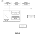
- FIG. 2 is a schematic block diagram of a video signal decoding apparatus 200 according to an embodiment of the present invention.
- the decoding apparatus 200 of the present invention includes an entropy decoding unit 210, an inverse quantization unit 220, an inverse transformation unit 225, a filtering unit 230, and a prediction unit 250.
- the entropy decoding unit 210 entropy-decodes a video signal bitstream to extract transform coefficient information, intra encoding information, inter encoding information, and the like for each region. For example, the entropy decoding unit 210 may obtain a binarization code for transform coefficient information of a specific region from the video signal bitstream. The entropy decoding unit 210 obtains a quantized transform coefficient by inverse-binarizing a binary code. The inverse quantization unit 220 inverse-quantizes the quantized transform coefficient, and the inverse transformation unit 225 reconstructs a residual value by using the inverse-quantized transform coefficient. The video signal processing device 200 reconstructs an original pixel value by summing the residual value obtained by the inverse transformation unit 225 with a prediction value obtained by the prediction unit 250.
- the filtering unit 230 performs filtering on a picture to improve image quality. This may include a deblocking filter for reducing block distortion and/or an adaptive loop filter for removing distortion of the entire picture.
- the filtered picture is outputted or stored in the DPB 256 for use as a reference picture for the next picture.
- the prediction unit 250 includes an intra prediction unit 252 and an inter prediction unit 254.
- the prediction unit 250 generates a prediction picture by using the encoding type decoded through the entropy decoding unit 210 described above, transform coefficients for each region, and intra/inter encoding information.
- a decoded region of the current picture or other pictures including the current block may be used.
- a current picture that is, a picture (or, tile/slice) that performs intra prediction or intra BC prediction
- an intra picture or an I picture or, tile/slice
- a picture (or, tile/slice) that may perform all of intra prediction, inter prediction, and intra BC prediction is called an inter picture (or, tile/slice).
- the intra prediction unit 252 generates a prediction block using the intra encoding information and reconstructed samples in the current picture.
- the intra encoding information may include at least one of an intra prediction mode, a Most Probable Mode (MPM) flag, and an MPM index.
- MPM Most Probable Mode
- the intra prediction unit 252 predicts the sample values of the current block by using the reconstructed samples located on the left and/or upper side of the current block as reference samples.
- reconstructed samples, reference samples, and samples of the current block may represent pixels. Also, sample values may represent pixel values.
- the reference samples may be samples included in a neighboring block of the current block.
- the reference samples may be samples adjacent to a left boundary of the current block and/or samples may be samples adjacent to an upper boundary.
- the reference samples may be samples located on a line within a predetermined distance from the left boundary of the current block and/or samples located on a line within a predetermined distance from the upper boundary of the current block among the samples of neighboring blocks of the current block.
- the neighboring block of the current block may include the left (L) block, the upper (A) block, the below left (BL) block, the above right (AR) block, or the above left (AL) block.
- the inter prediction unit 254 generates a prediction block using reference pictures and inter encoding information stored in the DPB 256.
- the inter coding information may include motion information set (reference picture index, motion vector information, etc.) of the current block for the reference block.
- Inter prediction may include L0 prediction, L1 prediction, and bi-prediction.
- L0 prediction means prediction using one reference picture included in the L0 picture list
- L1 prediction means prediction using one reference picture included in the L1 picture list.
- one set of motion information e.g., motion vector and reference picture index
- up to two reference regions may be used, and the two reference regions may exist in the same reference picture or may exist in different pictures.
- two motion vectors may correspond to the same reference picture index or different reference picture indexes.
- the reference pictures may be displayed (or outputted) both before and after the current picture in time aspect.
- two reference regions used in the bi-prediction scheme may be regions selected from picture list L0 and picture list L1, respectively.
- the inter prediction unit 254 may obtain a reference block of the current block using a motion vector and a reference picture index.
- the reference block is in a reference picture corresponding to a reference picture index.
- a sample value of a block specified by a motion vector or an interpolated value thereof may be used as a predictor of the current block.
- an 8-tap interpolation filter for a luma signal and a 4-tap interpolation filter for a chroma signal may be used.
- the interpolation filter for motion prediction in sub-pel units is not limited thereto.
- the inter prediction unit 254 performs motion compensation to predict the texture of the current unit from motion pictures reconstructed previously.
- the inter prediction unit may use a motion information set.
- the prediction unit 250 may include an intra BC prediction unit (not shown).
- the intra BC prediction unit may reconstruct the current region by referring to a specific region including reconstructed samples in the current picture.
- the intra BC prediction unit obtains intra BC encoding information for the current region from the entropy decoding unit 210.
- the intra BC prediction unit obtains a block vector value of the current region indicating the specific region in the current picture.
- the intra BC prediction unit may perform intra BC prediction by using the obtained block vector value.
- the intra BC encoding information may include block vector information.
- the reconstructed video picture is generated by adding the predict value outputted from the intra prediction unit 252 or the inter prediction unit 254 and the residual value outputted from the inverse transformation unit 225. That is, the video signal decoding apparatus 200 reconstructs the current block using the prediction block generated by the prediction unit 250 and the residual obtained from the inverse transformation unit 225.
- FIG. 2 shows a decoding apparatus 200 according to an embodiment of the present invention, and separately displayed blocks logically distinguish and show the elements of the decoding apparatus 200.
- the elements of the above-described decoding apparatus 200 may be mounted as one chip or as a plurality of chips depending on the design of the device.
- the operation of each element of the above-described decoding apparatus 200 may be performed by a processor (not shown).
- FIG. 3 illustrates an embodiment in which a coding tree unit (CTU) is split into coding units (CUs) in a picture.
- a picture may be split into a sequence of coding tree units (CTUs).
- the coding tree unit is composed of an NXN block of luma samples and two blocks of chroma samples corresponding thereto.
- the coding tree unit may be split into a plurality of coding units.
- the coding tree unit is not split and may be a leaf node. In this case, the coding tree unit itself may be a coding unit.
- the coding unit refers to a basic unit for processing a picture in the process of processing the video signal described above, that is, intra/inter prediction, transformation, quantization, and/or entropy coding.
- the size and shape of the coding unit in one picture may not be constant.
- the coding unit may have a square or rectangular shape.
- the rectangular coding unit (or rectangular block) includes a vertical coding unit (or vertical block) and a horizontal coding unit (or horizontal block).
- the vertical block is a block whose height is greater than the width
- the horizontal block is a block whose width is greater than the height.
- a non-square block may refer to a rectangular block, but the present invention is not limited thereto.
- the coding tree unit is first split into a quad tree (QT) structure. That is, one node having a 2NX2N size in a quad tree structure may be split into four nodes having an NXN size.
- the quad tree may also be referred to as a quaternary tree. Quad tree split may be performed recursively, and not all nodes need to be split with the same depth.
- the leaf node of the multi-type tree may be a coding unit. If splitting for the coding unit is not indicated or the coding unit is not large for the maximum transform length, the coding unit is used as a unit of prediction and transform without further division. On the other hand, at least one of the following parameters in the above-described quad tree and multi-type tree may be predefined or transmitted through a high level set of RBSPs such as PPS, SPS, VPS, and the like.
- CTU size root node size of quad tree
- minimum QT size MinQtSize minimum allowed QT leaf node size
- maximum BT size MaxBtSize maximum allowed BT root node size
- Maximum TT size MaxTtSize maximum allowed TT root node size
- Maximum MTT depth MaxMttDepth maximum allowed depth of MTT split from QT's leaf node
- Minimum BT size MinBtSize minimum allowed BT leaf node size
- Minimum TT size MinTtSize minimum allowed TT leaf node size.
- the resolution information may be signaled from the encoder to the decoder.
- the resolution information may be binarized and signaled based on the variable length.
- signaling overhead may be reduced when signaling is performed based on an index corresponding to the smallest value (that is, foremost value).
- the resolution may be mapped to signaling indexes in the order from the high resolution to the low resolution.
- the decoder acquires a motion vector of each subblock of the current block through the CPMVs of the CPMV set. Further, the decoder acquires a predictor of each subblock based on a motion vector of each subblock and acquires a predictor of the current block by combining the predictors of the respective subblocks. The decoder may restore the current block using the acquired predictor of the current block.
- the decoder may derive CPMVs of the current block based on the motion vector information set acquired from the candidate list.
- the decoder may perform affine merge prediction by using motion vectors of the motion vector information set acquired from the candidate list as CPMVs of the current block without any separate motion vector differential value.
- the decoder may acquire a separate motion vector differential value for the CPMV of the current block.
- the decoder may acquire the CPMV of the current block by adding motion vectors of the motion vector information set acquired from the candidate list and the motion vector differential value.
- the decoder may separately signal a flag or an index indicating whether to use a separate motion vector differential value for affine motion compensation of the current block.
- the encoder/decoder may induce the predictor of the CPMV using an MV of a neighboring block.
- the MV of the neighboring block may include an MV which is not an MV of the affine-motion-compensated block.
- the encoder/decoder may use an MV at a preset location for each CPMV as a predictor of the CPMV.
- the preset location may be a part included in a block adjacent thereto.
- the encoder/decoder may determine CPMVs of mv0, mv1, and mv2.
- mv0 indicates a top-left CPMV
- mv1 indicates a top-right CPMV
- mv2 indicates a bottom-left CPMV.
- the encoder/decoder may use an MV corresponding to a preset location A, B, or C as a predictor of mv0.
- the encoder/decoder may use an MV corresponding to a preset location D or E as a predictor of mv1.
- the encoder/decoder may use an MV corresponding to a preset location F or G as a predictor of mv2.
- coordinates of the top-left, top-right, and bottom-left control points of the affine motion-predicted neighboring block may be expressed as (x_E0, y_E0), (x_E1, y_E1), and (x_E2, y_E2), respectively.
- the encoder/decoder may calculate predictors of CPMVs of the current block or the CPMVs corresponding to (v_0x, v_0y) and (v_1x, v_1y) according to [Equation 8].
- [Equation 9] and [Equation 10] below show a method of inducing an affine motion predictor according to an embodiment of the present invention.
- a plurality of CPMVs or a plurality of CPMV predictors may be used for affine motion compensation.
- the encoder/decoder may induce a CPMV or CPMV predictor from another CPMV or CPMV predictor.
- the encoder/decoder may induce (or generate) two CPMVs or two CPMV predictors through the above-described method and induce another CPMV or another CPMV predictor on the basis thereof.
- the encoder/decoder may determine a motion vector difference based on [Equation 11] below.
- IMvd compIdx abs_mvd_greater 0 _flag compIdx * abs_mvd_minus 2 compIdx + 2 * 1 ⁇ 2 * mvd_sign_flag compIdx
- m v 0 mv ⁇ 0 + mv d 0
- m v 1 mv ⁇ 1 + mv d 1 + mv d 0
- m v 0 mv ⁇ 0 + mv d 0
- m v 1 mv ⁇ 1 + mv d 1 + mv d 0
- m v 2 mv ⁇ 2 + mv d 2 + mv d 0
- a predictor for a difference of each CPMV may exist.
- a difference of a CPMV may be determined based on a difference of another CPMV. This is based on a similarity between differences of CPMVs. That is, if a predictor of one CPMV is determined, a predictor of another CPMV may be determined using a small amount of information since differences of the CPMVs are similar.
- a difference predictor of a CPMV may be signaled, and a difference from the difference predictor of the CPMV may be signaled from the encoder to the decoder.
- [Equation 12] assumes the case in which the 4-parameter model is used
- [Equation 13] assumes the case in which the 6-parameter model is used.
- the encoder/decoder may determine whether to use a subblock merge candidate or a merge candidate. For example, when a specific condition is satisfied, the decoder may parse merge_subblock flag indicating whether the subblock merge candidate is used.
- the specific condition may be a condition related to the block size.
- the condition may be a condition related to a width, a height, an area, or the like, or may be a condition including a combination thereof.
- a merge index denoting an index indicating a specific candidate within a candidate list may be parsed.
- the encoder/decoder may not perform parsing. That is, the encoder/decoder may parse the index in the case in which the maximum number of candidate lists is larger than 1.
- merge_subblock_idx or the merge index is not parsed, the encoder/decoder may infer that the value is 0.
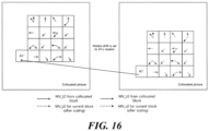
- the candidate when there are a plurality of candidates which can belong to the subblock merge candidate, it may be determined whether to add the candidates to the candidate list in consideration of the size of the current block if sizes of subblocks of the plurality of candidates are different. Further, the condition that considers the size of the current block with respect to any candidate may be based on the size of the subblock of the candidate.
- the candidate (before being added to the candidate list) may refer to an MVP method or mode, or can include all methods of making an MVP or an MV.
- the candidate added to the candidate list may refer to a candidate, MVP method, mode, or the like available for the current block.
- the encoder/decoder may determine a candidate to be added to the candidate list according to a block size condition of the current block. For example, the encoder/decoder may determine whether to add the candidate to the candidate list according to whether the size of the current block is larger than or equal to a threshold of the size of any block. Further, the block size condition or the threshold may be determined according to the subblock size of any candidate. This is because compression efficiency can be increased through subblock-based prediction in a block larger than the subblock or a block sufficiently larger block than the subblock. For example, in the case of a block equal to or smaller than the subblock, it may not be possible to acquire motion information in units of subblocks, which may not contribute to compression efficiency even though the subblock-based prediction is applied.
- the encoder/decoder may configure a first candidate list when the size of the current block is equal to or smaller than a preset size, and configure a second candidate list when the size of the current block is larger than or equal to the preset size.
- the type of candidates belonging to the second candidate list may include the type of candidates belonging to the first candidate list. For example, when the subblock size of a first mode is configured as a first subblock size and the subblock size of a second mode is configured as a second subblock size, the encoder/decoder may add only the second mode to the candidate list if the current block is equal to the preset size, and add both the first mode and the second mode to the candidate list if the current block is larger than the preset size.
- the first subblock size may be 8x8, and the second subblock size may be 4x4.
- the preset size may be 8x8.
- the preset size may have a width (or height) of 8.
- the first mode may be the SbTMVP
- the second mode may be the affine merge mode.
- the subblock-based merge candidate list may be configured (or generated) through the following method.
- the encoder/decoder may determine whether to parse a candidate index according to the block size condition of the current block. For example, when there are a plurality of candidates, the encoder/decoder may not parse a candidate index if all candidates except for one of the plurality of candidates are not added to the candidate list according to the block size condition and another condition. For example, when the number of candidates which can be added to the candidate list is two, the encoder/decoder may determine whether to parse candidate indexes according to the block size condition. For example, when one of the two candidates which can be added to the candidate list does not satisfy the block size condition, the encoder/decoder may not parse candidate indexes.
- [Table 4] below shows inter prediction-related syntax according to an embodiment of the present invention.
- [Table 5] below shows inter prediction-related syntax according to an embodiment of the present invention.
- the subblock mode when the width of the current block satisfies a specific condition or the height of the current block satisfies a specific condition, the subblock mode may be used. For example, this is because a plurality of subblocks may exist within the current block even though the width or the height of the current block is equal to the size of one side of the subblock size, if the width or the height is larger than the size of one side (or the size of another side) of the subblock size. Accordingly, when the width of the current block is larger than the width of the subblock or when the height of the current block is larger than the height of the subblock, the subblock mode may be used.
- the subblock mode may be used.
- the description that overlaps that in [Table 3] and [Table 4] is omitted.
- the encoder/decoder may use the subblock merge mode.
- the decoder may use the affine inter mode.
- [Table 6] and [Table 7] below show subblock merge-related syntax according to an embodiment of the present invention.
- [Table 6] if( (sps_affine_enabled_flag
- whether a specific mode is available may be signaled in a first unit.
- the encoder may signal information on which mode is actually used in a second unit belonging to the first unit to the decoder.
- whether a syntax element is parsed in the second unit may be determined according to a signaled value in the first unit.
- the first unit may be a sequence, a picture, a slice, a tile, or the like
- the second unit may be a CUT, a CU, or the like.
- the specific mode may be a subblock mode.
- the first unit may be referred to as a higher unit
- the second unit may be referred to as a lower unit.
- [Table 6] shows a signaling parsing process indicating whether the subblock mode is used in the case in which subblock sizes of modes belonging to the subblock mode are all the same or difference between the subblock sizes is not considered.
- the number of modes belonging to the subblock mode is plural and the number of signalings indicating whether higher units of modes corresponding to the subblock mode are available is plural, if at least one of the signalings indicating whether the plurality of higher units are available indicates availability, the subblock mode can be used in a lower unit. Further, signaling indicating whether higher units are available may correspond to a plurality of modes.
- information indicating whether higher units for the modes are available may be signaled. In this case, this may be combined and applied together with a condition such as a block size condition.
- availability of the subblock mode may mean that signaling indicating whether the subblock mode is available is parsed, and the above embodiments may be referred to therefor.
- the decoder may parse merge_subblock_flag only when at least one of sps_affine_enabled_flag and sps_sbtmvp_enabled_flag indicating whether the affine merge mode belonging to the subblock merge mode and the SbTMVP are available is 1.
- the decoder may parse a syntax element indicating whether the subblock mode is used in consideration thereof. According to an embodiment of the present invention, both signaling indicating whether a higher unit of any mode belonging to the subblock mode is available and a block size condition of the mode are satisfied, the encoder/decoder may use the subblock mode.
- first signaling indicating whether a higher unit corresponding to the first mode is available and second signaling indicating whether a higher unit corresponding to the second mode is available are used, and there are a first block size condition of the first mode and a second block size condition of the second mode, if the first signaling indicating whether the higher unit is available indicates that the higher unit is available and the first block size condition is satisfied, the encoder/decoder may use the subblock mode.
- the encoder/decoder may use the subblock mode.
- syntax elements sps_affine_enabled_flag and sps_sbtmvp_enabled_flag indicating whether the affine merge mode belonging to the subblock merge mode and the SbTMVP are available may be signaled from the encoder to the decoder.
- the decoder may parse merge_sub block_flag.
- the encoder may perform syntax signaling on merge_sub block_flag. ((sps_affine_enabled_flag && affine merge block size condition)
- [Table 8] below shows syntax indicating another example using the condition of [Table 7].
- [Table 8] if( (sps_affine_enabled_flag
- the encoder/decoder may parse merge_subblock_idx corresponding to the candidate index.
- whether the SbTMVP is available may be expressed by an availability flag.
- the availability flag indicating whether the SbTMVP is available may be availableFlagSbCol. Further, the SbTMVP may also be referred to as SbCol. Further, the availability flag having a value of 1 indicates that the SbTMVP is available, and the availability flag having a value of 0 indicates that the SbTMVP is not available.
- conditions of not using the SbTMVP may exist.
- the SbTMVP is not available based on the above-described higher unit signaling.
- a higher unit for the current block, the CU, or the PU may be a slice, a tile, a tile group, a sequence, a picture, a CTU, or the like.
- the higher unit signaling may include tile_group_temporal_mvp_enable_flag.
- tile_group_temporal_mvp_enable_flag indicates a flag indicating whether a temporal motion vector (or temporal motion vector prediction) is available.
- the encoder/decoder may configure the availability flag corresponding to the SbTMVP as 0. Otherwise, the availability flag may be determined through an additional operation.
- preset locations may be predefinedPosition1, predefinedPosition2, ..., predefinedPositionN, and the like.
- the reference order may be preset as predefinedPosition1, predefinedPosition2, ..., and predefinedPositionN.
- the reference order may be a forward direction or a backward direction of the reference order of merge candidate list construction.
- the reference order may be a forward direction or a backward direction of the reference order of AMVP candidate list construction.
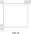
- the reference locations and the reference order may be A1, B1, B0, and AD.
- predefinedPosition1, predefinedPosition2, ..., and predefinedPositionN may indicate motion information corresponding to preset locations.
- the temporary motion vector may be configured as a zero motion vector. If motion information of the preset location is not available, the encoder/decoder may configure the temporary motion vector as the zero motion vector. When the motion information of the preset location is available, the motion information of the preset location may be configured as the temporary motion vector.
- the meaning of availability may include the case in which the corresponding location is not intra prediction. Alternatively, the meaning of availability may include the case in which the corresponding location is inter prediction. Alternatively, the meaning of availability may include the case in which a reference picture of motion information of the corresponding location is the same as a collocated picture corresponding to the current block. Alternatively, the meaning of availability may include the case in which a reference picture of motion information of the corresponding location is the same as a reference picture corresponding to the current block.
- the encoder/decoder may configure the motion information of the corresponding location as the temporary motion vector.
- the encoder/decoder may configure the temporary motion vector as the zero motion vector. This may be expressed by pseudo code as shown in [Table 12] below.
- the encoder/decoder may configure motion information of the first corresponding location that satisfies both the first availability condition and the second availability condition among the preset locations as the temporary motion vector.
- the encoder/decoder may configure the temporary motion vector as the zero motion vector. This may be expressed by pseudo code as shown in [Table 13] below.
- the encoder/decoder may also identify locations referred to after the location.
- the number of preset locations may be only one. This may be expressed by pseudo code as shown in [Table 14] below.
- the encoder/decoder may configure the temporary motion vector as the corresponding motion information. Otherwise, the encoder/decoder may configure the temporary motion vector as the zero motion vector.
- the one preset location may be the left location of the current block. That is, x coordinates of the one preset location may be smaller than left coordinates within the current block.
- the one preset location may be location A1.
- the motion information may include a motion vector (mvLX), a reference index (refIdxLX), a prediction utilization flag (predFlagLX), and the like.
- a process of identifying the second availability condition and configuring the temporary motion vector may be performed as follows. That is, if availableFlagN is true, the following process may be applied.
- availableFlagN When availableFlagN is true, it may mean that the first availability condition is satisfied.
- a parameter which can be availableFlagN may be availableFlag corresponding to the preset location.
- availableFlagN when only the location A1 is used, availableFlagN may be availableFlagA1, which may be a value indicating whether motion information of the location A1 is available.
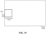
- FIG. 19 illustrates whether to use the SbTMVP according to an embodiment of the present invention.
- the encoder/decoder may determine whether a specific mode is used based on a location of a current block 1901.
- the encoder/decoder may determine whether a specific mode is used based on a location of a merge list sharing area to which the current block 1901 belongs.
- the encoder/decoder may determine whether the SbTMVP is used based on the location of the current block 1901. According to another embodiment of the present invention, whether to use the SbTMVP may be determined based on the location of the merge list sharing area to which the current block 1901 belongs. As an embodiment, the location of the current block 1901 or the location of the merge list sharing area to which the current block belongs may be top-left coordinates or may be expressed from the top-left coordinates. Further, the location of the current block 1901 or the location of the merge list sharing area to which the current block 1901 belongs may be a relative location within a higher group. The higher group may include a picture, a tile, a tile group, a CTU, a slice, and the like.
- the higher group may be a group to which the current block belongs. That is, for example, the encoder/decoder may determine whether to use the SbTMVP based on a location within a picture 1902 of the current block 1901.
- the current block or the merge list sharing area of the current block may be referred to as a current area.
- the encoder/decoder may determine whether to use the SbTMVP based on whether the current area borders a boundary of the higher group. For example, when the current area borders the boundary of the higher group, it may be determined or decided that the SbTMVP is not used. Alternatively, whether to use the SbTMVP may be determined based on whether the preset location referred to for determining the temporary motion vector corresponding to the current area described in FIG. 19 is out of the higher group. For example, when all of the preset locations referred to for determining the temporary motion vector corresponding to the current area are out of the higher group, the encoder/decoder may determine or decide that the SbTMVP is not used.
- whether all of the preset locations referred to for determining the temporary motion vector corresponding to the current area are out of the higher group may be determined based on coordinates of the current area. This is because, when all of the preset locations referred to for determining the temporary motion vector corresponding to the current area are out of the higher group, the zero motion vector may be used as the temporary motion vector and accordingly prediction performance of the SbTMVP may deteriorate. In an embodiment, in this case, by determining that the SbTMVP is not available, another mode signaled through the same syntax element as the SbTMVP may be signaled using the smaller number of bits.
- the encoder/decoder may configure availableFlagSbCol based on the location of the current area. That is, the encoder/decoder may configure availableFlagSbCol based on coordinate (xCb, yCb) indicating the current area. For example, (xCb, yCb) may be top-left coordinates of the current area.
- the subblock merge mode may include a first mode and a second mode in addition to the SbTMVP.
- syntax elements sps_mode1_enabled_flag and sps_mode2_enabled_flag indicating whether the first mode and the second mode are available may be signaled.
- the encoder/decoder may not parse merge_sub block_flag.
- the encoder/decoder may infer that merge_sub block_flag is 0.
- the encoder/decoder may parse merge_subblock_flag.
- Conditions of parsing merge_subblock_flag may include an additional condition as well as the above-described conditions. Referring to [Table 15], in order to determine parsing of merge_subblock_flag, a condition related to MaxNumSubblockMergeCand indicating the maximum number of subblock merge candidates and a condition related to the block size may also be considered.
- the encoder/decoder may configure MaxNumSubblockMergeCand as 1.
- the encoder/decoder may configure MaxNumSubblockMergeCand as 1.
- the encoder/decoder may configure MaxNumSubblockMergeCand as 0.
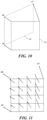
- FIG. 20 illustrates a method of inducing the SbTMVP according to an embodiment of the present invention.
- a preset location referred to for determining a temporary motion vector may be variable.
- the number of preset locations referred to for determining a temporary motion vector for a specific block may be configured as one, and the locations may be variable.
- the preset location referred to for determining the temporary motion vector may be determined as a top location of the current block 2001 or the current area.
- the top location of the current area may be a location having y coordinates smaller than y coordinates of the current area (that is, vertical direction coordinates).
- the preset location referred to for determining the temporary motion vector may be the location B1 of (a) of FIG. 18 .
- the preset location referred to for determining the temporary motion vector may be determined as a left location of the current block 2001 or the current area.
- the left location of the current area may be a location having x coordinates smaller than x coordinates of the current area (that is, horizontal direction coordinates).
- the preset location referred to for determining the temporary motion vector may be a location A1 of (a) of FIG. 18 .
- the subblock-based motion compensation method has been described.
- a method of applying a combination of embodiments for a merge mode-based motion compensation method using a motion vector difference (Merge mode with MVD (MMVD)) (or a merge MVD) and the subblock-based motion compensation is described.
- FIG. 21 illustrates an MMVD application method according to an embodiment of the present invention.
- the encoder/decoder may determine a Motion Vector (MV) based on a Motion Vector Predictor (MVP) and a Motion Vector Difference (MVD).
- the MVP may be referred to as base motion vector (baseMV). That is, the encoder/decoder may induce the motion vector (that is, a final motion vector) by adding the base motion vector and the motion vector difference.
- the present invention is not limited to the names, and the MVP may be referred to as a base motion vector, a temporary motion vector, an initial motion vector, an MMVD candidate motion vector, or the like.
- the MVD may be expressed by a value for refining the MVP, and may be referred to as a refined motion vector (refineMV) or a merge motion vector difference.
- a candidate index indicating a specific candidate among the two candidates may be signaled from the encoder to the decoder.
- a base candidate index which is an index for signaling the base motion vector may be defined.
- the encoder/decoder may determine a candidate applied to the current block among the candidates of the candidate list according to the base candidate index and determine a motion vector of the determined candidate as the base motion vector.
- the base candidate index is not limited to the name, and may be referred to as a base candidate index, a candidate index, a candidate flag, an MMVD index, an MMVD candidate index, an MMVD candidate flag, or the like.
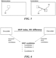
- the MVD in the MMVD may be differently defined from the MVD described in FIGs. 6 and 7 .
- the MMVD may indicate a merge mode using a motion vector difference (that is, a motion compensation mode or method) or indicate a motion vector difference in the case in which the MMVD is applied.
- the encoder/decoder may determine whether to apply (or use) the MMVD.
- the encoder/decoder may induce a merge candidate used for inter prediction of the current block from the merge candidate list and determine a motion vector of the current block by inducing the MMVD and applying (or adding) the MMVD to a motion vector of the merge candidate.
- the different MVD may be a simplified MVD, an MVD having a different (or small) resolution, MVDs having the small usable number, MVDs having different signaling methods, or the like.
- the MVD used in the conventional AMVP, affine inter mode, or the like described in FIGs. 6 and 7 may indicate all areas in x and y axes (that is, horizontal and vertical directions), for example, areas based on pictures (for example, picture areas or areas including pictures and surrounding areas) at uniform intervals for a specific signal unit (for example, x-pel), the MMVD may have a relatively limited unit of specific signaling. Further, areas (or units) for signaling the MMVD may not have uniform intervals.
- the MMVD may indicate only a specific direction for the specific signaling unit.
- the MMVD may be determined based on a distance and a direction.
- the distance and the direction of the MMVD according to a distance index indicating the distance of the MMVD and a direction index indicating the direction of the MMVD may be preset.
- the distance may indicate the MMVD size (for example, an absolute value) in units of specific pixels
- the direction may indicate the direction of the MMVD.
- the encoder/decoder may signal a relatively small distance through a relatively small index. That is, if the signaling is not signaling through fixed length binarization, the encoder/decoder may signal a relatively short distance through relatively small bits.
- the MVD may use a signaled MV or an MV based on the signaled MV.
- the MV based on the signaled MV may have a sign opposite to the sign of the signaled MV.
- MVD signaling may be performed based on a value corresponding to any reference list, and a value corresponding to another reference list different from the reference list may be the same as the value corresponding to the reference list (that is, signaled MVD) or have an opposite sign.
- Whether the reference list is the same as the value or has the opposite sign may be determined by a Picture Order Count (POC) relation between the current picture and a reference picture of the reference list and a POC relation between the current picture and a reference picture of another reference list different from the reference list. More specifically, only one MVD may be signaled even when both a reference list L0 and a reference list L1 are used. For example, the MVD corresponding to L0 may be signaled. Further, the MVD corresponding to L1 may be determined based on the MVD corresponding to L0.
- POC Picture Order Count
- the MVD corresponding to L1 may be a value which is the same as the MVD corresponding to L0 or has a sign changed from the sign of the MVD corresponding to L0. Further, this may be determined by a POC relation between the current picture and an L0 reference picture and a POC relation between the current picture and an L1 reference picture.
- whether to use the MVD corresponding to L0 which is the same as the MVD corresponding to L1 or the MVD corresponding to L0 which has the changed sign may be determined according to whether a value of (RefPicList0[refIdxLN0], currPic) * DiffPicOrderCnt(currPic, RefPicList1[refIdxLN1]) is larger than or smaller than 0.
- the decoder may parse the base motion vector index only when MaxNumMergeCand indicating the maximum number of merge candidates is larger than 1. If there is no base motion vector index, for example, when the base motion vector index has not been parsed and thus does not exist, the decoder may infer that the value is 0. This is because the determination may be performed even though signaling is not performed when the maximum number of available candidates is 1.
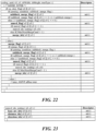
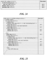
- FIG. 25 illustrates MMVD syntax according to an embodiment of the present invention.
- the MMVD flag is always parsed even when the skip mode or the merge mode is used without using the MMVD. Further, in both cases in which the MMVD is used and is not used, the base motion vector index or the merge index is parsed. Meanwhile, the MMVD flag may not be parsed when the skip mode or the merge mode is used without using the MMVD in the embodiment of FIG. 25 .
- the decoder is mainly described in FIG. 25 for convenience of the description, the coding process according to the present embodiment may be applied to the encoder through substantially the same method.
- the base motion vector-related syntax and the merge index may be defined as the same value.
- the base motion vector index and the merge index may be the same as each other. That is, signaling for indicating the corresponding candidate through one syntax element may be performed.
- the decoder may parse base motion vector-related syntax and parse the MMVD flag according to the condition. When the MMVD flag indicates that the MMVD is used, MMVD-related syntax as well as the base motion vector-related syntax may be parsed.
- the merge index after the merge index is parsed, it may be identified whether the corresponding candidate is a candidate which can be used for the MMVD.
- the MMVD flag may be parsed when the candidate can be used for the MMVD, and the MMVD flag may not be parsed when the candidate cannot be used for the MMVD.
- the MMVD flag does not exist, it may be inferred that the MMVD is not used. For example, when the number of base motion vectors of the MMVD can be num_mmvd_baseCand in the front of the merge candidate list (in a direction of the small index), if parsed indexes are smaller than num_mmvd_baseCand, the MMVD flag may be parsed.
- the MMVD is not used without parsing the MMVD flag.
- num_mmvd_baseCand candidate indexes or more are used, there is an advantage of reducing bits for the MMVD flag.
- the merge flag when the MMVD flag indicates that the MMVD is used, the merge flag may not be parsed. For example, a base motion vector candidate of the MMVD may be determined from merge candidates, and the decoder may not parse the merge flag when the MMVD flag indicates that the MMVD is used.
- MMVD flag When the MMVD is used (MMVD flag is 1), it may be inferred from the merge flag that the merge mode is used. Referring to FIG. 26 , when the skip mode is used, that is, when cu_skip_flag is 1, the decoder may infer that the merge flag is 1 regardless of the use of the MMVD.
- the merge flag when the subblock merge flag is positioned higher than the merge flag and the subblock merge flag is 1, the merge flag may not be parsed and it may be inferred that the merge flag is 1.
- the MMVD flag When the subblock merge flag is positioned higher than the MMVD flag and the subblock merge flag is 1, the MMVD flag may not be parsed and it may be inferred that the MMVD flag is 0.
- 1 of modeX_flag may mean that modeX is used, and 0 of modex_flag may mean that modeX is not used.
- the MMVD flag exists ahead of the merge flag. Further, when the MMVD flag is 1, the decoder may parse MMVD-related syntax. When the MMVD flag is 0, the decoder may parse the merge flag. When the MMVD flag is 0 and the merge flag is 1, the decoder may parse the merge index. In this case, an additional condition for parsing the index may exist.
- the merge index to be actually used may be determined by adding the parsed merge index and num_mmvd_baseCand corresponding to the number of candidates which can be used as the base motion vectors of the MMVD.
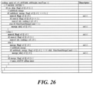
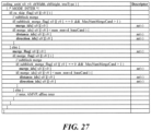
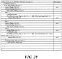
- FIG. 28 illustrates MMVD syntax according to an embodiment of the present invention.
- the candidate index may exist ahead of a flag indicating whether the candidate index uses a mode.
- the candidate index may exist ahead of the MMVD flag or the merge flag.
- it may be determined whether the MMVD flag is parsed according to whether the parsed index is a candidate which can use the MMVD.
- the MMVD flag is parsed when the parsed candidate index is the candidate which can use the MMVD, and the MMVD flag is not parsed and it may be inferred that the MMVD flag is 0 when the passed candidate index is a candidate which cannot use the MMVD.
- the merge flag may be parsed. Through the merge flag, it may be determined whether the merge mode, the subblock merge mode, the inter mode, the AMVP mode, or the affine inter mode is used.
- the decoder is mainly described in FIG. 28 for convenience of the description, the coding process according to the present embodiment may be applied to the encoder through substantially the same method.
- the MMVD flag may be parsed when the merge index is smaller than num_mmvd_baseCand corresponding to the number of candidates which can use the MMVD.
- the MMVD flag may not be parsed and, in this case, it may be inferred that the MMVD flag is 0.
- the MMVD flag is 1, a distance index (distance _idx) and a direction index (direction _idx) indicating an MMVD-related syntax element may be parsed.
- the merge flag is parsed, and accordingly, the merge mode, the subblock merge mode, the inter mode, the AMVP mode, or the affine mode may be identified.
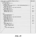
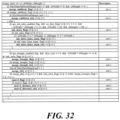
- FIG. 29 illustrates a coding unit syntax structure according to an embodiment of the present invention.
- a merge data that is, merge_data
- the decoder is mainly described in FIG. 29 for convenience of the description, the coding process according to the present embodiment may be applied to the encoder through substantially the same method.
- the merge data may include a portion of merge-related syntax.
- the merge data may be referred to as merge data syntax.
- the merge data may include a syntax parsing process performed when the merge flag is 1 in FIGs. 21 to 28 described above.
- 1 of the merge flag may mean that the merge mode is used.
- 1 of the merge flag may mean that inter prediction that does not use mvd_coding indicated by FIG. 6 and [Table 1] above is used.
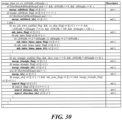
- the multi-hypothesis prediction when predicted blocks are generated, may be a method of generating and combining two or more predicted blocks.
- the multi-hypothesis prediction when predicted blocks are generated, may be a method using both inter prediction and intra prediction.
- the inter prediction and the intra prediction when prediction is performed, may be methods using pictures which are different from or the same as a picture included in the current block.
- a multi-hypothesis prediction flag indicates a syntax element indicating whether multi-hypothesis prediction is used.
- the triangle prediction is a method of performing motion compensation on an area which is not a rectangle within the current block. That is, in the triangle prediction, the unit having the same motion vector within the current block may not be a rectangle.
- a triangle prediction flag (that is, merge_triangle_flag) indicates a syntax element indicating whether the triangle prediction is used.
- the MMVD flag may be parsed earlier than signaling (or syntax element) indicating that another merge other than the MMVD is used.
- Signaling indicating that another merge other than the MMVD is used may include a multi-hypothesis prediction flag, a merge subblock flag, a merge triangle flag, and the like.
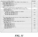
- an MMVD merge index (that is, mmvd_merge_idx)(or an MMVD index) indicates a syntax element indicating which is used as the base motion vector of the MMVD. If the MMVD is used, it may be inferred that the merge index is an MMVD merge flag (that is, mmvd_merge_flag)(or an MMVD flag).
- signaling indicating a base motion vector of the MMVD may exist as a syntax element separated from the merge index.
- signaling indicating the base motion vector of the MMVD may be the MMVD merge flag.
- the MMVD flag may be parsed after it is determined that the conventional merge mode or the MMVD is used.
- a step of acquiring the information related to the motion vector difference may include a step of acquiring a fourth syntax element indicating a distance of the motion vector difference and a step of acquiring a fifth syntax element indicating a direction of the emotion vector difference.
- the fourth syntax element may be a distance index (or an MMVD distance index)
- the fifth syntax element may be a direction index (or an MMVD direction index).
Landscapes
- Engineering & Computer Science (AREA)
- Multimedia (AREA)
- Signal Processing (AREA)
- Physics & Mathematics (AREA)
- Discrete Mathematics (AREA)
- General Physics & Mathematics (AREA)
- Compression Or Coding Systems Of Tv Signals (AREA)
Applications Claiming Priority (6)
| Application Number | Priority Date | Filing Date | Title |
|---|---|---|---|
| KR20180126782 | 2018-10-23 | ||
| KR20180137704 | 2018-11-09 | ||
| KR20190000479 | 2019-01-02 | ||
| KR20190016537 | 2019-02-13 | ||
| EP19875756.9A EP3873093B1 (de) | 2018-10-23 | 2019-10-23 | Verfahren zur verarbeitung eines videosignals unter verwendung einer subblockbasierten bewegungskompensation |
| PCT/KR2019/014016 WO2020085800A1 (ko) | 2018-10-23 | 2019-10-23 | 서브블록 기반의 모션 보상을 이용한 비디오 신호 처리 방법 및 장치 |
Related Parent Applications (2)
| Application Number | Title | Priority Date | Filing Date |
|---|---|---|---|
| EP19875756.9A Division EP3873093B1 (de) | 2018-10-23 | 2019-10-23 | Verfahren zur verarbeitung eines videosignals unter verwendung einer subblockbasierten bewegungskompensation |
| EP19875756.9A Division-Into EP3873093B1 (de) | 2018-10-23 | 2019-10-23 | Verfahren zur verarbeitung eines videosignals unter verwendung einer subblockbasierten bewegungskompensation |
Publications (2)
| Publication Number | Publication Date |
|---|---|
| EP4580190A2 true EP4580190A2 (de) | 2025-07-02 |
| EP4580190A3 EP4580190A3 (de) | 2025-08-27 |
Family
ID=70332151
Family Applications (2)
| Application Number | Title | Priority Date | Filing Date |
|---|---|---|---|
| EP25165249.1A Pending EP4580190A3 (de) | 2018-10-23 | 2019-10-23 | Verfahren zur verarbeitung eines videosignals unter verwendung von subblockbasierter bewegungskompensation |
| EP19875756.9A Active EP3873093B1 (de) | 2018-10-23 | 2019-10-23 | Verfahren zur verarbeitung eines videosignals unter verwendung einer subblockbasierten bewegungskompensation |
Family Applications After (1)
| Application Number | Title | Priority Date | Filing Date |
|---|---|---|---|
| EP19875756.9A Active EP3873093B1 (de) | 2018-10-23 | 2019-10-23 | Verfahren zur verarbeitung eines videosignals unter verwendung einer subblockbasierten bewegungskompensation |
Country Status (6)
| Country | Link |
|---|---|
| US (3) | US12273564B2 (de) |
| EP (2) | EP4580190A3 (de) |
| JP (5) | JP7206382B2 (de) |
| KR (3) | KR102708052B1 (de) |
| CN (5) | CN113196751B (de) |
| WO (1) | WO2020085800A1 (de) |
Families Citing this family (16)
| Publication number | Priority date | Publication date | Assignee | Title |
|---|---|---|---|---|
| JP7295231B2 (ja) | 2018-06-29 | 2023-06-20 | 北京字節跳動網絡技術有限公司 | Lutとamvpの間の相互作用 |
| CN119653077A (zh) * | 2018-10-29 | 2025-03-18 | 华为技术有限公司 | 一种视频图像预测方法及装置 |
| CN118828012A (zh) * | 2018-12-07 | 2024-10-22 | 夏普株式会社 | 运动图像解码装置以及运动图像编码装置 |
| MX2021007225A (es) * | 2018-12-17 | 2021-09-21 | Interdigital Vc Holdings Inc | Combinacion de herramientas de codificacion de diferencia de vector de movimiento con otros modos de movimiento. |
| EP3900354A4 (de) * | 2018-12-21 | 2022-09-14 | Sharp Kabushiki Kaisha | Systeme und verfahren zur interprädiktion in der videocodierung |
| WO2020142279A1 (en) | 2018-12-31 | 2020-07-09 | Vid Scale, Inc. | Combined inter and intra prediction |
| JP7275286B2 (ja) * | 2019-01-10 | 2023-05-17 | 北京字節跳動網絡技術有限公司 | Lut更新の起動 |
| KR20240137710A (ko) * | 2019-02-20 | 2024-09-20 | 베이징 다지아 인터넷 인포메이션 테크놀로지 컴퍼니 리미티드 | 비디오 코딩에서 장기 참조 픽처에 대한 제한받는 움직임 벡터 도출 |
| US20200288175A1 (en) * | 2019-03-06 | 2020-09-10 | Qualcomm Incorporated | Signaling of triangle merge mode indexes in video coding |
| EP3937489B1 (de) * | 2019-03-08 | 2024-08-14 | Jvckenwood Corporation | Bewegtbildkodierungsvorrichtung, bewegtbildkodierungsverfahren, bewegtbildkodierungsprogramm, bewegtbilddekodierungsvorrichtung, bewegtbilddekodierungsverfahren, und bewegtbilddekodierungsprogramm |
| WO2020192611A1 (en) | 2019-03-22 | 2020-10-01 | Beijing Bytedance Network Technology Co., Ltd. | Interaction between merge list construction and other tools |
| AU2020295272B2 (en) * | 2019-06-19 | 2023-12-14 | Lg Electronics Inc. | Image decoding method for deriving prediction sample on basis of default merge mode, and device therefor |
| CN114258676A (zh) * | 2019-06-19 | 2022-03-29 | Lg电子株式会社 | 当最终无法选择当前块的预测模式时执行帧间预测的图像解码方法及其装置 |
| US11405628B2 (en) * | 2020-04-06 | 2022-08-02 | Tencent America LLC | Method and apparatus for video coding |
| KR20240124974A (ko) * | 2021-12-15 | 2024-08-19 | 에프쥐 이노베이션 컴퍼니 리미티드 | 비디오 데이터를 코딩하기 위한 디바이스 및 방법 |
| US12425643B2 (en) | 2022-04-11 | 2025-09-23 | Qualcomm Incorporated | Derivation of affine merge candidates with linear regression for video coding |
Family Cites Families (22)
| Publication number | Priority date | Publication date | Assignee | Title |
|---|---|---|---|---|
| JPWO2012121284A1 (ja) * | 2011-03-10 | 2014-07-17 | シャープ株式会社 | 画像復号装置、画像符号化装置、および符号化データのデータ構造 |
| US9143795B2 (en) * | 2011-04-11 | 2015-09-22 | Texas Instruments Incorporated | Parallel motion estimation in video coding |
| BR112013030347B1 (pt) * | 2011-06-27 | 2022-06-28 | Sun Patent Trust | Método de decodificação de imagem, método de codificação de imagem, aparelho de decodificação de imagem, aparelho de codificação de imagem e aparelho de codificação e de decodificação de imagem |
| US20130070855A1 (en) * | 2011-09-17 | 2013-03-21 | Qualcomm Incorporated | Hybrid motion vector coding modes for video coding |
| KR20130050407A (ko) * | 2011-11-07 | 2013-05-16 | 오수미 | 인터 모드에서의 움직임 정보 생성 방법 |
| KR102413529B1 (ko) * | 2014-06-19 | 2022-06-24 | 마이크로소프트 테크놀로지 라이센싱, 엘엘씨 | 통합된 인트라 블록 카피 및 인터 예측 모드 |
| SG11201703454XA (en) * | 2014-11-18 | 2017-06-29 | Mediatek Inc | Method of bi-prediction video coding based on motion vectors from uni-prediction and merge candidate |
| CN107925758B (zh) * | 2015-08-04 | 2022-01-25 | Lg 电子株式会社 | 视频编译系统中的帧间预测方法和设备 |
| WO2017039117A1 (ko) * | 2015-08-30 | 2017-03-09 | 엘지전자(주) | 영상의 부호화/복호화 방법 및 이를 위한 장치 |
| US20190028731A1 (en) * | 2016-01-07 | 2019-01-24 | Mediatek Inc. | Method and apparatus for affine inter prediction for video coding system |
| WO2017171107A1 (ko) * | 2016-03-28 | 2017-10-05 | 엘지전자(주) | 인터 예측 모드 기반 영상 처리 방법 및 이를 위한 장치 |
| CN117221598A (zh) | 2016-06-22 | 2023-12-12 | Lx 半导体科技有限公司 | 图像编码/解码方法以及图像数据的传输方法 |
| CN109479141B (zh) | 2016-07-12 | 2023-07-14 | 韩国电子通信研究院 | 图像编码/解码方法和用于所述方法的记录介质 |
| US10979732B2 (en) * | 2016-10-04 | 2021-04-13 | Qualcomm Incorporated | Adaptive motion vector precision for video coding |
| CN110024384A (zh) * | 2016-10-06 | 2019-07-16 | Lg电子株式会社 | 基于帧间预测模式处理视频的方法和用于该方法的设备 |
| US20180310017A1 (en) * | 2017-04-21 | 2018-10-25 | Mediatek Inc. | Sub-prediction unit temporal motion vector prediction (sub-pu tmvp) for video coding |
| US20200154124A1 (en) * | 2017-07-04 | 2020-05-14 | Lg Electronics Inc. | Image decoding method based on inter prediction and image decoding apparatus therefor |
| CN118784832A (zh) * | 2017-09-12 | 2024-10-15 | 三星电子株式会社 | 对运动信息进行编码和解码的方法和发送比特流的方法 |
| WO2020141833A1 (ko) | 2019-01-02 | 2020-07-09 | 디지털인사이트 주식회사 | 영상 복호화 방법, 영상 부호화 방법, 영상 복호화 장치, 영상 부호화 장치 및 컴퓨터 판독 가능한 기록 매체 |
| US10869050B2 (en) | 2019-02-09 | 2020-12-15 | Tencent America LLC | Method and apparatus for video coding |
| WO2020227678A1 (en) | 2019-05-08 | 2020-11-12 | Beijing Dajia Internet Information Technology Co., Ltd. | Methods and apparatuses for signaling of merge modes in video coding |
| US11611759B2 (en) | 2019-05-24 | 2023-03-21 | Qualcomm Incorporated | Merge mode coding for video coding |
-
2019
- 2019-10-23 CN CN201980069820.7A patent/CN113196751B/zh active Active
- 2019-10-23 CN CN202311226819.5A patent/CN117156130A/zh active Pending
- 2019-10-23 CN CN202311227743.8A patent/CN117156131A/zh active Pending
- 2019-10-23 CN CN202311223481.8A patent/CN117156129A/zh active Pending
- 2019-10-23 KR KR1020237021844A patent/KR102708052B1/ko active Active
- 2019-10-23 JP JP2021521968A patent/JP7206382B2/ja active Active
- 2019-10-23 KR KR1020217012537A patent/KR102550530B1/ko active Active
- 2019-10-23 EP EP25165249.1A patent/EP4580190A3/de active Pending
- 2019-10-23 KR KR1020247030872A patent/KR20240142593A/ko active Pending
- 2019-10-23 EP EP19875756.9A patent/EP3873093B1/de active Active
- 2019-10-23 CN CN202311222783.3A patent/CN117156128A/zh active Pending
- 2019-10-23 WO PCT/KR2019/014016 patent/WO2020085800A1/ko not_active Ceased
-
2021
- 2021-04-19 US US17/234,688 patent/US12273564B2/en active Active
-
2022
- 2022-12-28 JP JP2022212171A patent/JP7400072B2/ja active Active
-
2023
- 2023-07-27 US US18/360,645 patent/US12273566B2/en active Active
- 2023-11-30 JP JP2023203318A patent/JP7551179B2/ja active Active
-
2024
- 2024-08-27 JP JP2024145683A patent/JP7685284B2/ja active Active
-
2025
- 2025-03-05 US US19/071,202 patent/US20250247565A1/en active Pending
- 2025-05-09 JP JP2025078932A patent/JP2025114757A/ja active Pending
Also Published As
| Publication number | Publication date |
|---|---|
| CN117156128A (zh) | 2023-12-01 |
| US20210243476A1 (en) | 2021-08-05 |
| JP2025114757A (ja) | 2025-08-05 |
| KR20210057188A (ko) | 2021-05-20 |
| JP7206382B2 (ja) | 2023-01-17 |
| EP4580190A3 (de) | 2025-08-27 |
| CN113196751B (zh) | 2023-10-13 |
| KR102550530B1 (ko) | 2023-07-04 |
| US12273566B2 (en) | 2025-04-08 |
| CN113196751A (zh) | 2021-07-30 |
| CN117156131A (zh) | 2023-12-01 |
| JP7551179B2 (ja) | 2024-09-17 |
| JP2023036907A (ja) | 2023-03-14 |
| KR20240142593A (ko) | 2024-09-30 |
| KR20230104758A (ko) | 2023-07-10 |
| CN117156130A (zh) | 2023-12-01 |
| JP7400072B2 (ja) | 2023-12-18 |
| US12273564B2 (en) | 2025-04-08 |
| KR102708052B1 (ko) | 2024-09-23 |
| EP3873093B1 (de) | 2025-05-21 |
| US20250247565A1 (en) | 2025-07-31 |
| WO2020085800A1 (ko) | 2020-04-30 |
| JP2024161597A (ja) | 2024-11-19 |
| JP2024023483A (ja) | 2024-02-21 |
| JP2022505578A (ja) | 2022-01-14 |
| JP7685284B2 (ja) | 2025-05-29 |
| EP3873093A1 (de) | 2021-09-01 |
| CN117156129A (zh) | 2023-12-01 |
| US20240040156A1 (en) | 2024-02-01 |
| EP3873093A4 (de) | 2022-07-20 |
Similar Documents
| Publication | Publication Date | Title |
|---|---|---|
| US12273566B2 (en) | Method and device for processing video signal by using subblock-based motion compensation | |
| US12200200B2 (en) | Video signal processing method and device using motion compensation | |
| EP4135329B1 (de) | Verfahren zur codierung und decodierung von bildinformationen und vorrichtung damit | |
| KR102736117B1 (ko) | 비디오 코딩에서 변환 블록 크기 제한 | |
| EP4007282B1 (de) | Videosignalverarbeitungsverfahren und -vorrichtung | |
| KR20250021642A (ko) | 모션 후보 리스트 구성 프로세스의 조건부 구현 | |
| EP3896969B1 (de) | Videosignalverarbeitung unter verwendung einer aktuellen bildreferenz | |
| CN114979662A (zh) | 利用阿尔法通道对图像/视频进行编解码的方法 | |
| CN114979661A (zh) | 利用阿尔法通道对图像/视频进行编解码的方法 | |
| KR20250173586A (ko) | 기하학적 분할 모드 코딩을 갖는 모션 후보 리스트 |
Legal Events
| Date | Code | Title | Description |
|---|---|---|---|
| PUAI | Public reference made under article 153(3) epc to a published international application that has entered the european phase |
Free format text: ORIGINAL CODE: 0009012 |
|
| STAA | Information on the status of an ep patent application or granted ep patent |
Free format text: STATUS: REQUEST FOR EXAMINATION WAS MADE |
|
| 17P | Request for examination filed |
Effective date: 20250321 |
|
| AC | Divisional application: reference to earlier application |
Ref document number: 3873093 Country of ref document: EP Kind code of ref document: P |
|
| AK | Designated contracting states |
Kind code of ref document: A2 Designated state(s): AL AT BE BG CH CY CZ DE DK EE ES FI FR GB GR HR HU IE IS IT LI LT LU LV MC MK MT NL NO PL PT RO RS SE SI SK SM TR |
|
| REG | Reference to a national code |
Ref country code: DE Ref legal event code: R079 Free format text: PREVIOUS MAIN CLASS: H04N0019700000 Ipc: H04N0019463000 |
|
| PUAL | Search report despatched |
Free format text: ORIGINAL CODE: 0009013 |
|
| AK | Designated contracting states |
Kind code of ref document: A3 Designated state(s): AL AT BE BG CH CY CZ DE DK EE ES FI FR GB GR HR HU IE IS IT LI LT LU LV MC MK MT NL NO PL PT RO RS SE SI SK SM TR |
|
| RIC1 | Information provided on ipc code assigned before grant |
Ipc: H04N 19/463 20140101AFI20250718BHEP Ipc: H04N 19/52 20140101ALI20250718BHEP Ipc: H04N 19/70 20140101ALI20250718BHEP |
|
| P01 | Opt-out of the competence of the unified patent court (upc) registered |
Free format text: CASE NUMBER: UPC_APP_0010991_4580190/2025 Effective date: 20251024 |