EP4580168A1 - Elektronische vorrichtung mit antriebsmotor - Google Patents
Elektronische vorrichtung mit antriebsmotor Download PDFInfo
- Publication number
- EP4580168A1 EP4580168A1 EP23877572.0A EP23877572A EP4580168A1 EP 4580168 A1 EP4580168 A1 EP 4580168A1 EP 23877572 A EP23877572 A EP 23877572A EP 4580168 A1 EP4580168 A1 EP 4580168A1
- Authority
- EP
- European Patent Office
- Prior art keywords
- housing
- electronic device
- disposed
- rack
- slide
- Prior art date
- Legal status (The legal status is an assumption and is not a legal conclusion. Google has not performed a legal analysis and makes no representation as to the accuracy of the status listed.)
- Pending
Links
Images


Classifications
-
- H—ELECTRICITY
- H02—GENERATION; CONVERSION OR DISTRIBUTION OF ELECTRIC POWER
- H02K—DYNAMO-ELECTRIC MACHINES
- H02K7/00—Arrangements for handling mechanical energy structurally associated with dynamo-electric machines, e.g. structural association with mechanical driving motors or auxiliary dynamo-electric machines
- H02K7/06—Means for converting reciprocating motion into rotary motion or vice versa
-
- H—ELECTRICITY
- H02—GENERATION; CONVERSION OR DISTRIBUTION OF ELECTRIC POWER
- H02K—DYNAMO-ELECTRIC MACHINES
- H02K7/00—Arrangements for handling mechanical energy structurally associated with dynamo-electric machines, e.g. structural association with mechanical driving motors or auxiliary dynamo-electric machines
- H02K7/14—Structural association with mechanical loads, e.g. with hand-held machine tools or fans
-
- H—ELECTRICITY
- H04—ELECTRIC COMMUNICATION TECHNIQUE
- H04M—TELEPHONIC COMMUNICATION
- H04M1/00—Substation equipment, e.g. for use by subscribers
- H04M1/02—Constructional features of telephone sets
- H04M1/0202—Portable telephone sets, e.g. cordless phones, mobile phones or bar type handsets
- H04M1/0206—Portable telephones comprising a plurality of mechanically joined movable body parts, e.g. hinged housings
- H04M1/0208—Portable telephones comprising a plurality of mechanically joined movable body parts, e.g. hinged housings characterized by the relative motions of the body parts
- H04M1/0235—Slidable or telescopic telephones, i.e. with a relative translation movement of the body parts; Telephones using a combination of translation and other relative motions of the body parts
- H04M1/0237—Sliding mechanism with one degree of freedom
-
- H—ELECTRICITY
- H04—ELECTRIC COMMUNICATION TECHNIQUE
- H04M—TELEPHONIC COMMUNICATION
- H04M1/00—Substation equipment, e.g. for use by subscribers
- H04M1/02—Constructional features of telephone sets
- H04M1/0202—Portable telephone sets, e.g. cordless phones, mobile phones or bar type handsets
- H04M1/026—Details of the structure or mounting of specific components
- H04M1/0264—Details of the structure or mounting of specific components for a camera module assembly
-
- H—ELECTRICITY
- H04—ELECTRIC COMMUNICATION TECHNIQUE
- H04M—TELEPHONIC COMMUNICATION
- H04M1/00—Substation equipment, e.g. for use by subscribers
- H04M1/02—Constructional features of telephone sets
- H04M1/0202—Portable telephone sets, e.g. cordless phones, mobile phones or bar type handsets
- H04M1/026—Details of the structure or mounting of specific components
- H04M1/0266—Details of the structure or mounting of specific components for a display module assembly
- H04M1/0268—Details of the structure or mounting of specific components for a display module assembly including a flexible display panel
-
- H—ELECTRICITY
- H05—ELECTRIC TECHNIQUES NOT OTHERWISE PROVIDED FOR
- H05K—PRINTED CIRCUITS; CASINGS OR CONSTRUCTIONAL DETAILS OF ELECTRIC APPARATUS; MANUFACTURE OF ASSEMBLAGES OF ELECTRICAL COMPONENTS
- H05K1/00—Printed circuits
- H05K1/02—Details
- H05K1/14—Structural association of two or more printed circuits
- H05K1/144—Stacked arrangements of planar printed circuit boards
Definitions
- An electronic device may include a rollable electronic device (e.g., the slidable electronic device) in which a display area of a flexible display (e.g., the rollable display) may be expanded and/or contracted depending on the operating state.
- the rollable electronic device may include a first housing and a second housing that are movably coupled with respect to one another in a manner that is at least partially fitted together.
- first housing and the second housing may be slidably operated with respect to one another and support at least a portion of a flexible display (e.g., the rollable display, an expandable display, or a stretchable display), such that the flexible display is induced to have a first display area in a slide-in state, and to have a second display area larger than the first display area in a slide-out state.
- a flexible display e.g., the rollable display, an expandable display, or a stretchable display
- the electronic device may include a driving motor including a pinion gear that automatically operates a second housing to slide a designated reciprocating distance on the basis of a first housing that is disposed in an inner space and is gripped by a user as a driving module, and a rack including a rack gear that is gear-coupled to the pinion gear.
- a driving motor including a pinion gear that automatically operates a second housing to slide a designated reciprocating distance on the basis of a first housing that is disposed in an inner space and is gripped by a user as a driving module
- a rack including a rack gear that is gear-coupled to the pinion gear.
- a rack that has a length along the sliding direction and is gear-coupled to the pinion gear may be disposed in the remaining housing.
- the rack since the rack must have a length at least corresponding to the sliding distance of the electronic device, there may be a problem that the surrounding electrical components must be designed to avoid the rack installation space and/or the rack accommodation space.
- the battery among the electrical components is designed to avoid the rack installation space or the accommodation space, its size may be reduced, and the usage time of the electronic device may be reduced because of the reduced battery capacity.
- Various embodiments of the present disclosure may provide an electronic device including a drive motor that can help make the electronic device slimmer through an efficient disposition structure between a drive module (e.g., a rack) and peripheral electrical components.
- a drive module e.g., a rack
- Various embodiments may provide an electronic device including a drive motor having a disposition structure for securing battery capacity.
- an electronic device may comprise: a first housing; a second housing slidably coupled to the first housing; a flexible display having a display area that is variable on the basis of the slide-in or slide-out of the second housing; a driving motor disposed in the second housing and including a pinion gear; a rack fixedly coupled to the first housing and including a rack gear driven by being gear-coupled to the pinion gear; and a rack guide disposed in the second housing and protecting the rack from external impact, wherein the rack guide may be disposed on the left side of the driving motor and spatially overlap with a camera module, and while the pinion gear and the rack gear are being driven by being gear-coupled to each other, the second housing may be configured to be driven to slide-in or slide-out on the basis of the reciprocating movement of the rack into the rack guide.
- an electronic device may comprise: a first housing; a second housing slidably coupled to the first housing; a flexible display having a display area that is variable on the basis of the slide-in or slide-out of the second housing; a driving motor disposed in the second housing and including a pinion gear; a rack fixedly coupled to the first housing and including a rack gear driven by being gear-coupled to the pinion gear; and a battery disposed in parallel with the rack, wherein, when viewing the side surface of the first housing from the outside in a direction perpendicular to the sliding direction, the rack and the battery may be disposed so as not to overlap each other.
- An electronic device may help slim down the electronic device through an efficient disposition structure of electrical components overlapping with the rack.
- the electronic device may help secure the capacity of the battery to the maximum by having a disposition structure in which a drive motor including a rack and a pinion gear coupled thereto is disposed so as not to overlap with a battery, thereby helping improve the operating time of the electronic device.
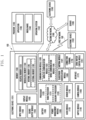
- FIG. 1 is a block diagram illustrating an electronic device 101 in a network environment 100 according to various embodiments.
- commands or data may be transmitted or received between the electronic device 101 and the external electronic device 104 via the server 108 coupled with the second network 199.
- Each of the electronic device 102 or 104 may be a device of a same type as, or a different type, from the electronic device 101.
- all or some of operations to be executed at the electronic device 101 may be executed at one or more of the external electronic device 102, 104, or 108.
- the electronic device 101 instead of, or in addition to, executing the function or the service, may request the one or more external electronic devices to perform at least part of the function or the service.
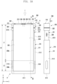
- the flexible display 230 may have a variable length in a sliding direction (e.g., direction 1 or direction 2) according to the sliding movement of the second housing 220 relative to the first housing 210.
- the flexible display 230 may have a first display area (e.g., the area corresponding to the first portion 230a) corresponding to a first length L1 in a slide-in state.
- the electronic device 200 may include at least one of an input device (e.g., the microphone 203-1), an audio output device (e.g., the call receiver 206 and/or a speaker 207), a sensor module 204 and 217, a camera module (e.g., the first camera module 205 or the second camera module 216), a connector port 208, a key input device 219, or an indicator (not shown) disposed in the second space 2201 of the second housing 220.
- the electronic device 200 may include another input device (e.g., the microphone 203) disposed in the first housing 210.
- the electronic device 200 may be configured such that at least one of the above-described components is omitted, or other components are additionally included. In some embodiments, at least one of the components described above may be disposed in the first space 2101 of the first housing 210.
- the input device may include a microphone 203-1.
- the input device e.g., the microphone 203-1) may include a plurality of microphones disposed to detect the direction of sound.
- the audio output device may include, for example, a call receiver 206 and a speaker 207.
- the speaker 207 may be in contact with the outside through at least one speaker hole formed in the second housing 220 at a position that is always exposed to the outside (e.g., the fourth side surface 2211), regardless of the slide-in/slide-out state.
- the connector port 208 may be in contact with the outside through a connector port hole formed in the second housing 220 in the slide-out state.
- the connector port 208 may be covered so as not to be visible from the outside in the slide-in state.
- the connector port 208 may be formed in the first housing 210 in a slide-in state and may be externally responsive through an opening formed to correspond with the connector port hole.
- the call receiver 206 may include a speaker (e.g., the piezo speaker) that is operated without a separate speaker hole.
- the sensor modules 204 and 217 may generate electrical signals or data values corresponding to an internal operating state of the electronic device 200 or an external environmental state.
- the sensor modules 204 and 217 may include, for example, a first sensor module 204 (e.g., the proximity sensor or the ambient light sensor) disposed on the front surface of the electronic device 200 and/or a second sensor module 217 (e.g., the heart rate monitoring (HRM) sensor) disposed on the rear surface of the electronic device 200.
- the first sensor module 204 may be disposed on the front surface of the electronic device 200 under the flexible display 230.
- the first sensor module 204 and/or the second sensor module 217 may include at least one of a proximity sensor, an ambient light sensor, a time of flight (TOF) sensor, an ultrasonic sensor, a fingerprint recognition sensor, a gesture sensor, a gyro sensor, a barometric pressure sensor, a magnetic sensor, an acceleration sensor, a grip sensor, a color sensor, an infrared (IR) sensor, a biometric sensor, a temperature sensor, or a humidity sensor.
- the camera module may include a first camera module 205 disposed on the front surface of the electronic device 200 and a second camera module 216 disposed on the rear surface of the electronic device 200.
- the electronic device 200 may also include a flash (not shown) disposed near the second camera module 216.
- the camera modules 205 and 216 may include one or more lenses, an image sensor, and/or an image signal processor.
- the first camera module 205 may be disposed under the flexible display 230 and configured to capture a subject through a portion of an active area (e.g., the display area) of the flexible display 230.
- the first camera module 205 and, among the sensor modules 204 and 217, the first sensor module 204 may be disposed to detect an external environment through the flexible display 230.
- the first camera module 205 or the first sensor module 204 may be disposed in the second space 2201 of the second housing 220 so as to be in contact with the external environment through a transparent area or a perforated opening formed in the flexible display 230.
- an area of the flexible display 230 facing the first camera module 205 may be formed as a transparent area having a designated transmittance as part of an active area that displays content.
- the transparent area may be formed to have a transmittance in a range of about 5% to about 20%.
- the slide-in operation and/or the slide-out operation of the electronic device 200 may be performed automatically.
- the slide-in operation and/or the slide-out operation of the electronic device 200 may be performed through gear engagement between a driving motor (e.g., the driving motor 260 of FIG. 4 ) including a pinion gear (e.g., the pinion gear 261 of FIG. 4 ) disposed in a second space 2201 of the second housing 220 and a rack (e.g., the rack 2253 of FIG. 4 ) disposed in the first space 2101 of the first housing 210, extending to at least a portion of the second space 2201, and including a rack gear coupled to the pinion gear 261.
- a driving motor e.g., the driving motor 260 of FIG. 4
- a rack e.g., the rack 2253 of FIG. 4
- a processor e.g., the processor 120 of FIG. 1
- the processor may drive a driving motor (e.g., the driving motor 260 of FIG. 4 ) disposed inside the electronic device 200.
- the triggering signal may include a signal according to selection (e.g., touch) of an object displayed on the flexible display 230 or a signal according to operation (e.g., pressing) of a physical button (e.g., the key button) included in the electronic device 200.
- the electronic device 200 may have a structure in which the second housing 220 slides in and/or out relative to the first housing 210 along a longitudinal direction (e.g., vertical direction) (e.g., ⁇ y-axis direction) of the electronic device 200, but is not limited thereto.
- the electronic device 200 may have a structure in which the second housing 220 slides in and/or out relative to the first housing 210 along a width direction (e.g., horizontal direction) (e.g., the ⁇ x-axis direction) perpendicular to the longitudinal direction of the electronic device 200.
- the electronic device 200 may be formed such that the length of the first side surface 2111 of the first housing 210 is longer than the length of the second side surface 2112.
- the length of the fourth side surface 2211 of the second housing 220 may also be formed to be longer than the length of the fifth side surface 2212.
- the electronic device 200 may include at least one antenna A disposed through at least a portion of a second lateral member 221 of the second housing 220.
- the electronic device 200 may include at least one unit conductive portion 310, 311, and 312 formed through at least one segmentation portion 321, 322, 323, and 324.
- the electronic device 200 may include a first conductive portion 310 disposed through a first segmentation portion 321 and a second segmentation portion 322 spaced apart from each other by a specified interval on a fourth side surface 2211 of the second lateral member 221.
- the electronic device 200 may include a first segmentation portion 321 and a second conductive portion 311 disposed through a third segmentation portion 323 formed on a fifth side surface 2212. In one embodiment, the electronic device 200 may include a second segmentation portion 322 and a third conductive portion 312 disposed through a fourth segmentation portion 324 formed on a sixth side surface 2213. In one embodiment, at least one conductive portion among the first conductive portion 310, the second conductive portion 311, or the third conductive portion 312 may be electrically connected to a wireless communication circuit of the electronic device 200 (e.g., the wireless communication module 192 of FIG. 1 ) so as to be used as at least one antenna A operating in at least one designated frequency band (e.g., the legacy band or an NR band). For example, the at least one designated frequency band may cover a range of about 600 MHz to 9000 MHz.
- the first housing 210 may include a first lateral member 211 and a first rear cover 213 coupled to at least a portion of the first lateral member 211 (e.g., at least a portion of the first extension member 212).
- the first space 2101 may be formed by the coupling of the first lateral member 211 and the first rear cover 213.
- the second housing 220 may include a second lateral member 221, a second rear cover 223 coupled to at least a portion of the second lateral member 221 (e.g., at least a portion of the second extension member 222), and a window cover 224 coupled to the second rear cover 223.
- the drive module may include a driving motor 260 disposed in the second space 2201 and including a pinion gear 261, and a rack 2253 fixed to the support bracket 225 and extending from the first space 2101 to the second space 2201, and including a rack gear disposed to engage the pinion gear 261.
- the electronic device 200 may further include a reduction module (e.g., the reduction gear assembly) disposed to engage with the driving motor 260 to reduce the rotational speed and increase the driving force.
- the driving motor 260 may be disposed in the second space 2201 of the second housing 220 to be supported by a second extension member 222.
- the electronic device 200 may include a pair of guide rails 226 that are fixed to both sides of the support bracket 225 to guide both ends of the support member 240 in a sliding direction while simultaneously guiding the second housing 220 in a sliding direction.
- the support bracket 225 and the guide rails 226 may be fixed in the inner space 2101 of the first housing 210 through a fastening member, such as a screw.
- the electronic device 200 may include a first substrate 252 (e.g., the first sub-substrate) and an antenna member (e.g., the antenna member 253 of FIG. 13) disposed between a first extension member 212 and a first rear cover 213 in a first housing 210.
- the first substrate 252 and the antenna member e.g., the antenna member 253 of FIG. 13
- the first substrate 252 and the antenna member 253 may be electrically connected to a substrate assembly 251 through a flexible substrate (e.g., the flexible substrate F1 of FIG.
- the battery B disposed in the battery mounting portion 2251 of the support bracket 225 may be designed to expand in size as much as possible in the width direction (e.g., the ⁇ x-axis direction) without any separate component disposition other than the guide structure (e.g., the guide structure of the guide rail 226 and the second housing 220) between the support bracket 225 and the second housing 220.
- the width W of the battery B disposed in the battery mounting portion 2251 may be similar to or the same as the width of the electronic device 200 (e.g., the width of the electronic device in the x-axis direction). Such an expansion in the size of the battery B may help improve the reliability of the electronic device 200 by increasing the usage time of the device.
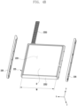
- FIG. 5a is a cross-sectional view of an electronic device as viewed along line 5a-5a of FIG. 2a according to various embodiments of the present disclosure.
- FIG. 5b is a cross-sectional view of an electronic device as viewed along line 5b-5b of FIG. 3a according to various embodiments of the present disclosure.
- the electronic device 200 may include a first housing 210 having a first space 2101, a second housing 220 having a second space 2201, a support member 240 connected to the second housing 220 and at least partially accommodated into the first space 2101 in a slide-in state, a flexible display 230 disposed to receive support from at least a portion of the support member 240 and at least a portion of the second housing 220, and a driving motor 260 including a pinion gear 261 fixed to the first space 2101 and gear-coupled to a rack 2253 extending into the second space 2201.
- the driving motor 260 may automatically move the second housing 220 in a slide-out direction (direction 1) or a slide-in direction (direction 2) on the basis of the first housing 210 through the gear engagement of the pinion gear 261 and the rack 2253.
- the electronic device 200 may include a first rear cover 213 coupled to a first extension member 212 extended from a first lateral member 211 of the first housing 210.
- the electronic device 200 may include a first substrate 252 and an antenna member 253 disposed in a space between the first extension member 212 and the first rear cover 213.
- the electronic device 200 may include a second rear cover 223 coupled to a second extension member 222 extending from a second lateral member 221 and a window cover 224 coupled to a portion of the second rear cover 223.
- a portion of the second housing 220 may be accommodated in the first space 2101 of the first housing 210 in the slide-in state (state of FIG. 5a ) of the electronic device 200.
- at least a portion of the flexible display 230 may be accommodated in a manner of being bent into the first space 2101 together with the support member 240, thereby being disposed so as not to be visible from the outside.
- the flexible display 230 may have a first display area (e.g., the display area corresponding to the first portion 230a of FIG. 3a ) exposed to the outside.
- the second housing 220 may be transitioned to a slide-out state in which it moves outwardly from the first housing 210 at least partially along the first direction (direction 1) by driving the driving motor 260.
- the flexible display 230 may be supported by the support bracket 225 and moved together with the support member 240 in the slide-out state (state of FIG. 5b ) of the electronic device 200, such that a portion that has slid in to the first space 2101 may be exposed so as to be at least partially visible from the outside.
- the flexible display 230 may be exposed to the outside with a second display area that is expanded more than the first display area (e.g., the display area including the first portion 230a and the second portion 230b of FIG. 3a ).
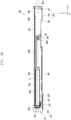
- the end of the rack 2253 in the slide-in state, as the second housing 220 moves in the second direction (direction 2), the end of the rack 2253 may be disposed to be in contact with or proximate to the upper inner surface 221a of the second space 2201.
- the end of the rack 2253 in the slide-out state, as the second housing 220 moves in the first direction (direction 1), the end of the rack 2253 may be disposed to move away from the upper inner surface 221a of the second space 2201, and at least a portion of the rack 2253 may still be disposed to receive support (e.g., guide) from the second housing 220 (e.g., the second extension member 222) in the second space 2201.
- support e.g., guide
- the rack 2253 may be formed to have a length corresponding to the distance from the support bracket 225 to the upper inner surface 221a of the second space 2201 in the slide-in state.
- the rack 2253 may have an interworking disposition structure that is fixed to the first space 2101 and accommodated (e.g., guided) in the second space 2201 of the second housing 220 according to a sliding motion.
- This interworking disposition structure prevents the rack 2253 and the battery B from overlapping when the side surface of the first housing 210 (e.g., the second side surface 2112 or the third side surface 2113) is viewed from the outside and when the flexible display 230 is viewed from above, thereby maximizing the size (e.g., battery capacity) of the battery B in the width direction (e.g., the ⁇ x-axis direction) and/or length direction (e.g., ⁇ y-axis direction) of the first housing 210, thereby helping increase the usage time of the electronic device 200 and improve the reliability of the device.
- the side surface of the first housing 210 e.g., the second side surface 2112 or the third side surface 2113
- the flexible display 230 is viewed from above
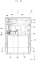
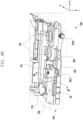
- FIG. 6a is a schematic diagram of an electronic device illustrating the disposition structure of a driving motor and a rack in a slide-in state according to various embodiments of the present disclosure.
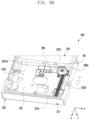
- FIG. 6b is a perspective view of a portion of an electronic device illustrating the disposition configuration of a rack accommodated in a second housing in a slide-in state according to various embodiments of the present disclosure.
- the electronic device 200 may include a driving motor 260 including a pinion gear 261 disposed in a second space 2201 of the second housing 220.
- the electronic device 200 may include a rack 2253 that is fixed to a support bracket 225 disposed in the first space 2101 of the first housing 210 and is disposed in the second space 2201 in a slide-in state.
- the rack 2253 may be fixed to a side wall 2251a formed on at least a portion of the support bracket 225 through a screw.
- the rack 2253 may be disposed such that, in a slide-in state, the second housing 220 moves in the second direction (direction 2 ), such that its end is in contact with or proximate to the upper inner surface 221a of the second space 2201.
- the rack 2253 may be moved while being guided by a rack guide 222a provided on the second extension member 222 according to the movement of the second housing 220.
- the rack guide 222a may help reduce unintended deformation or movement of the rack 2253 during a sliding motion of the electronic device 200.
- the rack guide 222a may include a recess formed lower than a surface of the second extension member 222 in the longitudinal direction (e.g., the ⁇ y-axis direction) along the accommodating trajectory of the rack 2253.
- the rack guide 222a may be disposed on or formed integrally with the second extension member 222 and may include a guide structure (e.g., a boss) that supports and guides at least the left and right side surfaces of the rack 2253.
- the rack guide 222a may be omitted.
- the pinion gear 261 and the rack 2253 coupled thereto may be disposed to be biased to one side with respect to the width direction (e.g., the ⁇ x-axis direction) of the electronic device 200, thereby helping secure the size of the substrate assembly 251 (e.g., main substrate) generally disposed in the center of the second space 2201.
- the substrate assembly 251 e.g., main substrate
- FIG. 6c is a cross-sectional view of an electronic device as viewed along line 6c-6c of FIG. 6a according to various embodiments of the present disclosure.
- the electronic device 200 may include a support member 240 for supporting a flexible display 230 and a pair of guide rails 226 for guiding both ends of the support member 240.
- the support member 240 may include a plurality of multi-bars 241 that are rotatably coupled to each other and guide protrusions 2411 that are protruded at both ends of each of the multi-bars 241.
- the guide rails 226 may be fixed to both sides of a support bracket 225 disposed in a first space 2101 of the first housing 210.
- the guide rails 226 may include guide slits 2261 formed at positions corresponding to the movement trajectories of the support member 240.
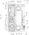
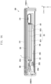
- FIG. 7a is a block diagram of an electronic device illustrating the disposition structure of a driving motor and a rack in a slide-out state according to various embodiments of the present disclosure.
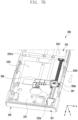
- FIG. 7b is a perspective view of a portion of an electronic device illustrating the disposition configuration of a rack accommodated in a second housing in a slide-out state according to various embodiments of the present disclosure.
- the rack 2253 may be disposed so that its end is away from the upper inner surface 221a of the second space 2201 when the second housing 220 is moved in the first direction (direction 1) in the slide-out state. In one embodiment, at least a portion of the rack 2253 may be disposed to be guided by the rack guide 222a of the second housing 220 in the slide-out state. In one embodiment, at least a portion of the rack 2253 may be disposed to be guided by the rack guide 222a provided in the second housing 220 even when transitioning from the slide-in state to the slide-out state, thereby ensuring operational stability.
- the sliding distance S (sliding stroke) for the second housing 220 to transition from a slide-in state to a slide-out state may be determined by the length of the rack 2253.
- the length of the rack 2253 may be determined by the distance from the support bracket 225 to the upper inner surface 221a of the second space 2201 when the electronic device 200 is in the slide-in state.
- the length and/or the sliding distance S of the rack 2253 may be determined by the size of the battery B mounted on the battery mounting portion 2251 of the support bracket 225.
- the size of the battery B along the longitudinal direction (e.g., ⁇ y-axis direction) of the electronic device 200 may be determined by the sliding distance S of the second housing 220.
- the size of the battery B is designed to be maximally expandable to correspond to the first space 2201 in response thereto, thereby helping extend the usage time of the electronic device 200.
- the battery B and the rack 2253 may have a structure in which they are disposed side by side without overlapping each other when viewing the side surface of the first housing 210 (e.g., the second side surface 2112 or the third side surface 2113 of FIG.
- the battery B is designed to be maximally expandable to a size substantially equal to or similar to the width of the first housing 210 along the width direction (e.g., the ⁇ x-axis direction) of the electronic device 200, thereby helping extend the usage time of the electronic device.
- FIGS. 8a and 8b may be similar to the electronic device of FIGS. 2a to 3b or may further include other embodiments of the electronic device.
- FIGS. 8a and 8b are diagrams illustrating the rear surface of the second housing 200 with the second rear surface cover 223 and the window cover 224 removed.
- FIG. 8c is a cross-sectional view of a portion of an electronic device taken along line 8c-8c of FIG. 8a according to various embodiments of the present disclosure.
- the second camera module 216 of the at least one electrical component may be disposed to overlap with at least a portion of the rack 2253 when the second rear surface cover 223 is viewed from above.
- the rack 2253 may be disposed to overlap with the second camera module 216 in a slide-in state.
- the second camera module 216 may be disposed to detect an external environment through the second rear surface cover 223. Accordingly, the rack 2253 may be disposed between the second camera module 216 and the second extension member 222 of the second lateral member 221 (or the flexible display 230) in the second space 2201.
- the rack 2253 may be disposed in a dead space between the second camera module 216 and the flexible display 230 (or the second extension member 222 at a position that is biased to one side of the electronic device 200, thereby helping improve the disposition efficiency of the electrical components (e.g., improving the design freedom of the substrate assembly and/or the second substrate).
- some of the electrical components among the at least one electrical component may be disposed to avoid overlapping with the rack 2253 when the second rear surface cover 223 is viewed from above.
- the microphone 203-1, the first camera module 205, the receiver 206, the speaker 207, or the array antenna (AR) may be disposed in the second space 2201 so as not to overlap with the rack 2253.
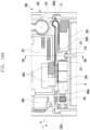
- FIG. 8d is a cross-sectional view of a portion of an electronic device taken along line 8d-8d of FIG. 8b according to various embodiments of the present disclosure.
- the electronic device 200 may include an array antenna (AR) (e.g., a mmWave module) disposed in a second space 2201 of a second housing 220.
- the array antenna (AR) may be disposed to be biased to one side of the upper inner surface 221a in consideration of the disposition of the rack 2253.
- the array antenna (AR) may include a substrate and a plurality of antenna elements disposed at a specified interval on the substrate, and the plurality of antenna elements may be configured to generally form a directional beam in a direction (e.g., the y-axis direction) toward the fourth side surface 2211 by being electrically connected to a wireless communication circuit (e.g., the wireless communication module 192 of FIG. 1 ).
- the array antenna (AR) as a mmWave module, may be configured to transmit or receive wireless signals in the range of about 3 GHz to 100 GHz.
- the electronic device 200 may include a heat dissipation structure for dissipating heat generated from the array antenna (AR) to the surroundings.
- the electronic device 200 may include a heat transfer member 259 disposed so that one end is proximate to or is in contact with the array antenna (AR) and the other end is proximate to or is in contact with the second extension member 222 and/or the speaker 207.
- the heat transfer member 259 and/or the second rear surface cover 223 may be formed of a metal material that is advantageous for heat diffusion.
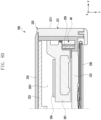
- FIG. 9a is a cross-sectional view of an electronic device taken along line 9a-9a of FIG. 8a according to various embodiments of the present disclosure.
- FIG. 9b is a perspective view illustrating a disposition structure of a substrate assembly and a connector port according to various embodiments of the present disclosure.
- the substrate assembly 251 may be disposed in a manner that a plurality of printed circuit boards (PCBs) 2511, 2512, and 2513 are stacked through an interposer I in the second space 2201.
- the substrate assembly 251 may include a first printed circuit board 2511, a second printed circuit board 2512, and a third printed circuit board 2513 that are sequentially stacked from the second extension member 222 in a direction (e.g., the -z-axis direction) toward the second rear surface cover 223.
- each of the printed circuit boards 2511, 2512, and 2513 may be electrically connected to each other through the interposer I.
- each of the printed circuit boards 2511, 2512, and 2513 may be disposed to at least partially overlap with the second rear surface cover 223 when viewed from above.
- a space below the protruding portion of the second printed circuit board 2512 may be provided as a rack accommodation space 251a for accommodating the rack 2253.
- the second printed circuit board 2512 may be formed to have the same size as the first printed circuit board 2511 but may be disposed to be pushed to one side with respect to the first printed circuit board 2511, thereby helping provide a rack accommodation space 251a.
- the protruding portion of the second printed circuit board 2512 may be used for disposing at least one electrical component.
- the connector port 208 may be disposed in that portion, thereby helping center-align the connector port 208 in the second space 2201.
- the rack 2253 may be accommodated in a rack accommodation space 251a provided in the substrate assembly 251, thereby helping slim down (e.g., reduce thickness) the electronic device 200 and improve the efficiency of disposition with peripheral electrical components.
- FIG. 10a is a block diagram of a portion of an electronic device according to various embodiments of the present disclosure.
- the electronic device 200 may include a flexible substrate F1 for electrically connecting a substrate assembly 251 disposed in a second space 2201 of a second housing 220 and a third substrate 255 (e.g., a small PCB) disposed in a first space 2101 of a first housing 210.
- the third substrate 255 may be fixed in the first space 2101 through a support bracket 225 and may be electrically connected to the first substrate 252 and/or the antenna member 253 disposed in the first housing 210.
- the first substrate 252 and the antenna member 253 may be electrically connected to the substrate assembly 251 through the third substrate 255 and the flexible substrate F1.
- the third substrate 255 may be disposed around the driving motor 260 and may include a charging IC for the battery B and/or a control circuit for the driving motor.
- FIG. 10b is a cross-sectional view of an electronic device taken along line 10b-10b of FIG. 10a according to various embodiments of the present disclosure.
- FIG. 10c is a cross-sectional view illustrating a slide-out state of the electronic device of FIG. 10a according to various embodiments of the present disclosure.
- the electronic device 200 may include at least one driving belt 270 (e.g., a life belt or a tension belt) to support the flexible display 230 and reduce lifting of the flexible display 230 by providing uniform tension during operation.
- the driving belt 270 may help reduce driving resistance because of eccentricity of the second housing 220 moved by driving the driving motor 260.
- FIG. 11 is a block diagram of an electronic device illustrating the disposition structure of an antenna member and a first substrate according to various embodiments of the present disclosure.
- the first substrate 251 and the antenna member 253 may be disposed to be electrically connected to the flexible substrate F1 in the first space 2101 after each of the first substrate 251 and the antenna member 253 passes through different through holes disposed in the first extension member 212.
- the electronic device 200 may include a microphone 203 as an input device that extends from the first substrate 251 and is disposed through a second through-hole 210b formed in the second side surface 2112 of the first housing 210.
- the first housing 210 may include a third through-hole 210c disposed in the second side surface 2112 and/or the third side surface 2113.
- the third through-hole 210c may be formed in a manner that connects the first space 2101 from the outside, and thus may be used as a fastening path for fastening a guide rail (e.g., the guide rail 226 of FIG. 4 ) to a support bracket (e.g., the support bracket 225 of FIG. 4 ) through a fastening member such as a screw through the third through-hole 210c.
- an electronic device may comprise: a first housing (e.g., the first housing 210 of FIG. 4a ); a second housing (e.g., the second housing 220 of FIG. 4a ) slidably coupled to the first housing; a flexible display (e.g., the flexible display 230 of FIG. 4a ) having a display area that is variable on the basis of the slide-in or slide-out of the second housing; a driving motor (e.g., the driving motor 260 of FIG. 4a ) disposed in the second housing and including a pinion gear (e.g., the pinion gear 261 of FIG.
- a first housing e.g., the first housing 210 of FIG. 4a
- a second housing e.g., the second housing 220 of FIG. 4a
- a flexible display e.g., the flexible display 230 of FIG. 4a
- a driving motor e.g., the driving motor 260 of FIG. 4a
- pinion gear e.g
- a rack e.g., the rack 2253 of FIG. 4a
- a rack guide e.g., the rack guide 222a of FIG. 6a
- the rack guide may be disposed on the left side of the driving motor and spatially overlap with a camera module, and while the pinion gear and the rack gear are being driven by being gear-coupled to each other, the second housing may be configured to be driven to slide-in or slide-out on the basis of the reciprocating movement of the rack into the rack guide.
- a multi-bar (e.g., the multi-bar 240 of FIG. 4a ) supporting the rear surface of a portion of the flexible display and a driving belt (e.g., the driving belt 270 of FIG. 10a ) connected to one end of the multi-bar and one end of the second housing may be disposed.
- a driving belt e.g., the driving belt 270 of FIG. 10a
- the driving belt may be disposed to be located in a central portion of the electronic device.
- the electronic device may include a substrate assembly disposed in the second housing, and the substrate assembly may include a first printed circuit board (PCB) (e.g., the first printed circuit board 2511 of FIG. 9a ), a second printed circuit board (e.g., the second printed circuit board 2512 of FIG. 9a ) stacked on the first printed circuit board, and an interposer I disposed therebetween to electrically connect the first printed circuit board and the second printed circuit board, wherein when the flexible display is viewed from above, the first printed circuit board and the second printed circuit board may be disposed to at least partially overlap.
- PCB printed circuit board
- the second printed circuit board e.g., the second printed circuit board 2512 of FIG. 9a
- the second printed circuit board may be disposed to include a portion that partially protrudes laterally from the first printed circuit board when the flexible display is viewed from above, and the rack may be disposed in a space overlapping with the protruding portion (e.g., the rack accommodation space 251a of FIG. 9a ).
- the rack may be disposed to overlap with at least a portion of the camera module when the flexible display is viewed from above in the slide-in state.
- the camera module may be disposed between the rack and the rear surface of the electronic device in the second housing.
- the camera module may be disposed in the second housing to detect an external environment through a rear surface of the second housing.
- the electronic device may include at least one electrical component disposed in the second housing, wherein the at least one electrical component may include at least one of a substrate assembly (e.g., the substrate assembly 251 of FIG. 8a ) disposed substantially centrally, at least one microphone (e.g., the microphone 203-1 of FIG. 8a ) disposed to surround the substrate assembly, at least one camera module (e.g., the first camera module 205 and the second camera module 216 of FIG. 8a ), and one of a receiver (e.g., the receiver 206 of FIG. 8a ), a speaker (e.g., the speaker 207 of FIG. 8a ), a connector port (e.g., the connector port 208 of FIG. 8a ), a vibration motor (e.g., the vibration motor 218 of FIG. 8a ), or an antenna module (e.g., the array antenna (AR) of FIG. 9a ).
- a substrate assembly e.g., the substrate assembly 251 of FIG. 8a
- a battery e.g., the battery B of FIG. 4a
- a side surface of the first housing e.g., the second side surface 2112 or the third side surface 2113 of FIG. 4a
- the rack and the battery may be disposed so as not to overlap each other.
- the rack and the battery when viewing the flexible display from above, may be disposed so as not to overlap.
- the length of the rack may be determined as the distance from the fixed portion of the rack to the upper inner surface of the second housing (e.g., the inner surface 221a of FIG. 5a ) in the slide- in state.
- the rack may be disposed so as to be proximate to or be in contact with an upper inner surface of the second housing in the slide-in state.
- the size of the battery may be determined by the length of the rack.
- an electronic device may comprise: a first housing (e.g., the first housing 210 of FIG. 4a ); a second housing (e.g., the second housing 220 of FIG. 4a ) slidably coupled to the first housing; a flexible display (e.g., the flexible display 230 of FIG. 4a ) having a display area that is variable on the basis of the slide-in or slide-out of the second housing; a driving motor (e.g., the driving motor 260 of FIG. 4a ) disposed in the second housing and including a pinion gear (e.g., the pinion gear 261 of FIG.
- a first housing e.g., the first housing 210 of FIG. 4a
- a second housing e.g., the second housing 220 of FIG. 4a
- a flexible display e.g., the flexible display 230 of FIG. 4a
- a driving motor e.g., the driving motor 260 of FIG. 4a
- pinion gear e.g
- a rack e.g., the rack 2253 of FIG. 4a
- a battery e.g., the battery B of FIG. 4a
- a side surface of the first housing e.g., the second side surface 2112 or the third side surface 2113 of FIG. 4a
- the rack and the battery may be disposed so as not to overlap each other.
- the rack may be disposed so as to be proximate to or be in contact with an upper inner surface of the second housing in the slide-in state.
- the size of the battery may be determined by the length of the rack.
Landscapes
- Engineering & Computer Science (AREA)
- Signal Processing (AREA)
- Power Engineering (AREA)
- Telephone Set Structure (AREA)
- Transmission Devices (AREA)
- Connection Of Motors, Electrical Generators, Mechanical Devices, And The Like (AREA)
Applications Claiming Priority (3)
| Application Number | Priority Date | Filing Date | Title |
|---|---|---|---|
| KR20220130549 | 2022-10-12 | ||
| KR1020220166823A KR20240050966A (ko) | 2022-10-12 | 2022-12-02 | 구동 모터를 포함하는 전자 장치 |
| PCT/KR2023/014979 WO2024080644A1 (ko) | 2022-10-12 | 2023-09-27 | 구동 모터를 포함하는 전자 장치 |
Publications (2)
| Publication Number | Publication Date |
|---|---|
| EP4580168A1 true EP4580168A1 (de) | 2025-07-02 |
| EP4580168A4 EP4580168A4 (de) | 2025-11-26 |
Family
ID=90669836
Family Applications (1)
| Application Number | Title | Priority Date | Filing Date |
|---|---|---|---|
| EP23877572.0A Pending EP4580168A4 (de) | 2022-10-12 | 2023-09-27 | Elektronische vorrichtung mit antriebsmotor |
Country Status (4)
| Country | Link |
|---|---|
| US (1) | US20250227170A1 (de) |
| EP (1) | EP4580168A4 (de) |
| CN (1) | CN120035983A (de) |
| WO (1) | WO2024080644A1 (de) |
Family Cites Families (7)
| Publication number | Priority date | Publication date | Assignee | Title |
|---|---|---|---|---|
| KR101107127B1 (ko) * | 2010-01-12 | 2012-01-31 | 주식회사 다이아벨 | 이동 단말기 |
| US10750073B2 (en) * | 2018-05-30 | 2020-08-18 | Guangdong Oppo Mobile Telecommunications Corp., Ltd. | Electronic device and photographing control method thereof |
| CN112991928B (zh) * | 2019-12-13 | 2022-08-16 | Oppo广东移动通信有限公司 | 电子装置 |
| US11315447B2 (en) * | 2020-05-26 | 2022-04-26 | Wuhan China Star Optoelectronics Semiconductor Display Technology Co., Ltd. | Display device |
| KR102905075B1 (ko) * | 2020-11-26 | 2025-12-29 | 엘지전자 주식회사 | 이동 단말기 |
| KR20220079365A (ko) * | 2020-12-04 | 2022-06-13 | 삼성전자주식회사 | 플렉서블 디스플레이를 포함하는 전자 장치 |
| KR102830792B1 (ko) * | 2021-01-26 | 2025-07-04 | 엘지전자 주식회사 | 플렉서블 디스플레이 장치 |
-
2023
- 2023-09-27 EP EP23877572.0A patent/EP4580168A4/de active Pending
- 2023-09-27 CN CN202380072525.3A patent/CN120035983A/zh active Pending
- 2023-09-27 WO PCT/KR2023/014979 patent/WO2024080644A1/ko not_active Ceased
-
2025
- 2025-03-25 US US19/089,622 patent/US20250227170A1/en active Pending
Also Published As
| Publication number | Publication date |
|---|---|
| US20250227170A1 (en) | 2025-07-10 |
| WO2024080644A1 (ko) | 2024-04-18 |
| CN120035983A (zh) | 2025-05-23 |
| EP4580168A4 (de) | 2025-11-26 |
Similar Documents
| Publication | Publication Date | Title |
|---|---|---|
| US12443223B2 (en) | Flexible display and electronic device including same | |
| US20250317507A1 (en) | Antenna and electronic device including the same | |
| US20250107022A1 (en) | Electronic device including rack gear guide structure | |
| KR20240050967A (ko) | 구동 모터를 포함하는 전자 장치 | |
| KR20230133739A (ko) | 구동 모터를 포함하는 전자 장치 | |
| US20240422925A1 (en) | Electronic device comprising driving motor | |
| US20250008011A1 (en) | Electronic apparatus including antenna | |
| EP4648220A1 (de) | Antenne und elektronische vorrichtung damit | |
| US12422886B2 (en) | Electronic device including drive motor | |
| EP4580168A1 (de) | Elektronische vorrichtung mit antriebsmotor | |
| KR20240050966A (ko) | 구동 모터를 포함하는 전자 장치 | |
| EP4583499A1 (de) | Elektronische vorrichtung mit antriebsmotor | |
| EP4582899A1 (de) | Elektronische vorrichtung mit antriebsmotor | |
| KR20240050968A (ko) | 구동 모터를 포함하는 전자 장치 | |
| KR20230133745A (ko) | 부품 배치 공간을 고려한 슬라이더블 전자 장치 | |
| EP4270909B1 (de) | Elektronische vorrichtung mit antriebsmotor | |
| US12469972B2 (en) | Electronic device comprising antenna | |
| EP4572547A1 (de) | Wasserdichte struktur und elektronische vorrichtung mit wasserdichter struktur | |
| EP4485693A1 (de) | Elektronische vorrichtung mit antennenelement | |
| US20250310430A1 (en) | Electronic device comprising retainer | |
| US20260059034A1 (en) | Electronic device including driving motor | |
| EP4462227A1 (de) | Aufrollbare elektronische vorrichtung mit mehrstangenstruktur | |
| KR20250046100A (ko) | 랙 기어 가이드 구조를 포함하는 전자 장치 | |
| CN120936967A (zh) | 包括磁体的可卷曲电子装置 | |
| KR20230133738A (ko) | 구동 모터를 포함하는 전자 장치 |
Legal Events
| Date | Code | Title | Description |
|---|---|---|---|
| STAA | Information on the status of an ep patent application or granted ep patent |
Free format text: STATUS: THE INTERNATIONAL PUBLICATION HAS BEEN MADE |
|
| PUAI | Public reference made under article 153(3) epc to a published international application that has entered the european phase |
Free format text: ORIGINAL CODE: 0009012 |
|
| STAA | Information on the status of an ep patent application or granted ep patent |
Free format text: STATUS: REQUEST FOR EXAMINATION WAS MADE |
|
| 17P | Request for examination filed |
Effective date: 20250328 |
|
| AK | Designated contracting states |
Kind code of ref document: A1 Designated state(s): AL AT BE BG CH CY CZ DE DK EE ES FI FR GB GR HR HU IE IS IT LI LT LU LV MC ME MK MT NL NO PL PT RO RS SE SI SK SM TR |
|
| A4 | Supplementary search report drawn up and despatched |
Effective date: 20251023 |
|
| RIC1 | Information provided on ipc code assigned before grant |
Ipc: H04M 1/02 20060101AFI20251017BHEP Ipc: H05K 1/11 20060101ALI20251017BHEP Ipc: H02K 7/116 20060101ALI20251017BHEP Ipc: H02K 7/06 20060101ALI20251017BHEP Ipc: H02K 7/14 20060101ALI20251017BHEP Ipc: H05K 1/14 20060101ALI20251017BHEP |
|
| DAV | Request for validation of the european patent (deleted) | ||
| DAX | Request for extension of the european patent (deleted) |