EP4270909B1 - Elektronische vorrichtung mit antriebsmotor - Google Patents
Elektronische vorrichtung mit antriebsmotor Download PDFInfo
- Publication number
- EP4270909B1 EP4270909B1 EP23706982.8A EP23706982A EP4270909B1 EP 4270909 B1 EP4270909 B1 EP 4270909B1 EP 23706982 A EP23706982 A EP 23706982A EP 4270909 B1 EP4270909 B1 EP 4270909B1
- Authority
- EP
- European Patent Office
- Prior art keywords
- electronic device
- housing
- disposed
- support
- circuit board
- Prior art date
- Legal status (The legal status is an assumption and is not a legal conclusion. Google has not performed a legal analysis and makes no representation as to the accuracy of the status listed.)
- Active
Links
Images


Classifications
-
- G—PHYSICS
- G06—COMPUTING OR CALCULATING; COUNTING
- G06F—ELECTRIC DIGITAL DATA PROCESSING
- G06F1/00—Details not covered by groups G06F3/00 - G06F13/00 and G06F21/00
- G06F1/16—Constructional details or arrangements
- G06F1/1613—Constructional details or arrangements for portable computers
- G06F1/1615—Constructional details or arrangements for portable computers with several enclosures having relative motions, each enclosure supporting at least one I/O or computing function
- G06F1/1624—Constructional details or arrangements for portable computers with several enclosures having relative motions, each enclosure supporting at least one I/O or computing function with sliding enclosures, e.g. sliding keyboard or display
-
- G—PHYSICS
- G06—COMPUTING OR CALCULATING; COUNTING
- G06F—ELECTRIC DIGITAL DATA PROCESSING
- G06F1/00—Details not covered by groups G06F3/00 - G06F13/00 and G06F21/00
- G06F1/16—Constructional details or arrangements
- G06F1/1613—Constructional details or arrangements for portable computers
- G06F1/1633—Constructional details or arrangements of portable computers not specific to the type of enclosures covered by groups G06F1/1615 - G06F1/1626
- G06F1/1635—Details related to the integration of battery packs and other power supplies such as fuel cells or integrated AC adapter
-
- G—PHYSICS
- G06—COMPUTING OR CALCULATING; COUNTING
- G06F—ELECTRIC DIGITAL DATA PROCESSING
- G06F1/00—Details not covered by groups G06F3/00 - G06F13/00 and G06F21/00
- G06F1/16—Constructional details or arrangements
- G06F1/1613—Constructional details or arrangements for portable computers
- G06F1/1633—Constructional details or arrangements of portable computers not specific to the type of enclosures covered by groups G06F1/1615 - G06F1/1626
- G06F1/1637—Details related to the display arrangement, including those related to the mounting of the display in the housing
- G06F1/1652—Details related to the display arrangement, including those related to the mounting of the display in the housing the display being flexible, e.g. mimicking a sheet of paper, or rollable
-
- H—ELECTRICITY
- H01—ELECTRIC ELEMENTS
- H01Q—ANTENNAS, i.e. RADIO AERIALS
- H01Q1/00—Details of, or arrangements associated with, antennas
- H01Q1/12—Supports; Mounting means
- H01Q1/22—Supports; Mounting means by structural association with other equipment or articles
- H01Q1/24—Supports; Mounting means by structural association with other equipment or articles with receiving set
- H01Q1/241—Supports; Mounting means by structural association with other equipment or articles with receiving set used in mobile communications, e.g. GSM
- H01Q1/242—Supports; Mounting means by structural association with other equipment or articles with receiving set used in mobile communications, e.g. GSM specially adapted for hand-held use
- H01Q1/243—Supports; Mounting means by structural association with other equipment or articles with receiving set used in mobile communications, e.g. GSM specially adapted for hand-held use with built-in antennas
-
- H—ELECTRICITY
- H04—ELECTRIC COMMUNICATION TECHNIQUE
- H04M—TELEPHONIC COMMUNICATION
- H04M1/00—Substation equipment, e.g. for use by subscribers
- H04M1/02—Constructional features of telephone sets
- H04M1/0202—Portable telephone sets, e.g. cordless phones, mobile phones or bar type handsets
- H04M1/0206—Portable telephones comprising a plurality of mechanically joined movable body parts, e.g. hinged housings
- H04M1/0208—Portable telephones comprising a plurality of mechanically joined movable body parts, e.g. hinged housings characterized by the relative motions of the body parts
- H04M1/0235—Slidable or telescopic telephones, i.e. with a relative translation movement of the body parts; Telephones using a combination of translation and other relative motions of the body parts
- H04M1/0237—Sliding mechanism with one degree of freedom
-
- H—ELECTRICITY
- H04—ELECTRIC COMMUNICATION TECHNIQUE
- H04M—TELEPHONIC COMMUNICATION
- H04M1/00—Substation equipment, e.g. for use by subscribers
- H04M1/02—Constructional features of telephone sets
- H04M1/0202—Portable telephone sets, e.g. cordless phones, mobile phones or bar type handsets
- H04M1/026—Details of the structure or mounting of specific components
- H04M1/0262—Details of the structure or mounting of specific components for a battery compartment
-
- H—ELECTRICITY
- H04—ELECTRIC COMMUNICATION TECHNIQUE
- H04M—TELEPHONIC COMMUNICATION
- H04M1/00—Substation equipment, e.g. for use by subscribers
- H04M1/02—Constructional features of telephone sets
- H04M1/0202—Portable telephone sets, e.g. cordless phones, mobile phones or bar type handsets
- H04M1/026—Details of the structure or mounting of specific components
- H04M1/0277—Details of the structure or mounting of specific components for a printed circuit board assembly
-
- G—PHYSICS
- G06—COMPUTING OR CALCULATING; COUNTING
- G06F—ELECTRIC DIGITAL DATA PROCESSING
- G06F1/00—Details not covered by groups G06F3/00 - G06F13/00 and G06F21/00
- G06F1/16—Constructional details or arrangements
- G06F1/1613—Constructional details or arrangements for portable computers
- G06F1/1633—Constructional details or arrangements of portable computers not specific to the type of enclosures covered by groups G06F1/1615 - G06F1/1626
- G06F1/1675—Miscellaneous details related to the relative movement between the different enclosures or enclosure parts
- G06F1/1681—Details related solely to hinges
-
- H—ELECTRICITY
- H04—ELECTRIC COMMUNICATION TECHNIQUE
- H04M—TELEPHONIC COMMUNICATION
- H04M1/00—Substation equipment, e.g. for use by subscribers
- H04M1/02—Constructional features of telephone sets
- H04M1/0202—Portable telephone sets, e.g. cordless phones, mobile phones or bar type handsets
- H04M1/026—Details of the structure or mounting of specific components
- H04M1/0266—Details of the structure or mounting of specific components for a display module assembly
- H04M1/0268—Details of the structure or mounting of specific components for a display module assembly including a flexible display panel
-
- H—ELECTRICITY
- H05—ELECTRIC TECHNIQUES NOT OTHERWISE PROVIDED FOR
- H05K—PRINTED CIRCUITS; CASINGS OR CONSTRUCTIONAL DETAILS OF ELECTRIC APPARATUS; MANUFACTURE OF ASSEMBLAGES OF ELECTRICAL COMPONENTS
- H05K1/00—Printed circuits
- H05K1/18—Printed circuits structurally associated with non-printed electric components
- H05K1/189—Printed circuits structurally associated with non-printed electric components characterised by the use of flexible or folded printed circuits
Definitions
- Various embodiments of the present disclosure relate to an electronic device including a driving motor.
- first housing and the second housing may operate to be slidable with respect to each other and support at least a portion of a rollable display (e.g., a flexible display, an expandable display, or a stretchable display) so that in a slide-in state the rollable display may be induced to have a first display area and in a slide-out state it may be induced to have a second display area larger than the first display area.
- a rollable display e.g., a flexible display, an expandable display, or a stretchable display
- the electronic device may be disposed between the first housing and the second housing, and it may include a manual slide module (e.g., a spring hinge module) in which the electronic device changes semi-automatically to a slide-in state or a slide-out state in the case of pressing in a direction to close or open above a certain inflection point.
- a manual slide module e.g., a spring hinge module
- the manual sliding structure may interfere with the smooth sliding operation because of the repulsive force of the rollable display to unfold, and it may be difficult to design so that the sliding operation is performed by distributing uniformly the repulsive force of the rollable display and the elastic force of the manual slide module (e.g., the spring hinge).
- the electronic device may include a driving module that includes a driving motor including a pinion gear that is disposed in an inner space and enables the second housing to slide automatically based on the first housing gripped by the user, and a rack gear that is gear-coupled with the pinion gear.
- a driving motor including a pinion gear that is disposed in an inner space and enables the second housing to slide automatically based on the first housing gripped by the user, and a rack gear that is gear-coupled with the pinion gear.
- the electronic device may automatically perform the sliding operation.
- Various embodiments of the present disclosure may provide an electronic device including a driving motor disposed to induce a relatively extended slide stroke.
- Various embodiments may provide an electronic device including a driving motor disposed to induce a minimization of an electrical connection structure.
- Various embodiments may provide a rollable electronic device provided with a support structure for supporting a rollable display in a slide-out state.
- an electronic device according to claim 1 is provided.
- Exemplary embodiments are provided in the dependent claims.
- the implementations described below are not all claimed, they are included to help understanding the context of the invention. While the description often refers of embodiments, the embodiments of the invention are those which comprise at least all the features of an independent claim. Any embodiment which does not fall within the scope of the claims does not form part of the invention, but is rather included as an illustrative example that is useful for understanding the invention.
- an electronic device may include a first housing including a first space formed through a first lateral member and a first printed circuit board disposed in the first space; a second housing slidably coupled to the first housing and including a second printed circuit board disposed in a second space formed through a second lateral member; a rear surface cover disposed on an outer surface of the first lateral member; at least one electronic component disposed between the first lateral member and the rear surface cover; a rollable display that is disposed to be supported by the first housing and the second housing and of whicha display area is expanded in the case of transitioning from a slide-in state where at least a portion of the second housing is accommodated in the first space to a slide-out state where moving in a first direction, wherein the first direction is a direction in which the display area is expanded; a driving motor disposed on the second space, connected electrically to at least one electronic component and including a pinion gear; and a rack gear disposed on the first space and gear-coupled with the pinion gear
- an electronic device may include a first housing including a first space in which a first extension member is disposed; a second housing slidably coupled to the first housing and including a second space; a support bracket disposed in the first space; a rollable display that is disposed to be supported by the first housing and the second housing and of which a display area is expanded in the case of transitioning from a slide-in state where at least a portion of the second housing is accommodated in the first space to a slide-out state where moving in a first direction, wherein the first direction is a direction in which the display area is expanded; at least one electronic component disposed in the second space; a driving motor disposed on the second space, connected electrically to at least one electronic component and including a pinion gear; and a rack gear disposed on the first space and gear-coupled with the pinion gear, wherein the support bracket includes a support part of which the outer surface is formed in curve to support at least a portion of the support member and a support plate extending from the support
- an electronic device may include a first housing including a first lateral member and a first extension member extending from the first lateral member to a first space; a second housing slidably coupled to the first housing and including a second lateral member and a second extension member extending from the second lateral member to a second space; a rollable display that is disposed to be supported by the first housing and the second housing and of whicha display area is expanded in the case of transitioning from a slide-in state where at least a portion of the second housing is accommodated in the first space to a slide-out state where moving in a first direction, wherein the first direction is a direction in which the display area is expanded; at least one electronic component disposed in the second space; a driving motor disposed on at least a portion of the second extension member, connected electrically to at least one electronic component and including a pinion gear; and a rack gear disposed through the first extension member and gear-coupled with the pinion gear, wherein the driving motor may be disposed at an edge
- An electronic device may provide an extended slide stroke corresponding to the length of a rack gear by including the rack gear disposed to be gear-coupled with a pinion gear of a driving motor in an inner space of a second housing that slides with respect to a first housing and in an inner space of a driving motor and the first housing disposed at an end in a slide-in direction.
- the electronic device may provide an efficient electrical connection structure with the driving motor by including electronic components (e.g., a board or a battery) disposed together with the driving motor in the inner space of the second housing.
- electronic components e.g., a board or a battery
- the electronic device may help improve the operational reliability of the electronic device by including a support structure disposed in an inner space of the first housing to support at least a portion of the rollable display in a slide-out state.
- FIG. 1 is a block diagram illustrating an electronic device 101 in a network environment 100 according to various embodiments.
- the electronic device 101 in the network environment 100 may communicate with an electronic device 102 via a first network 198 (e.g., a short-range wireless communication network), or at least one of an electronic device 104 or a server 108 via a second network 199 (e.g., a long-range wireless communication network).
- a first network 198 e.g., a short-range wireless communication network
- a second network 199 e.g., a long-range wireless communication network
- the electronic device 101 may communicate with the electronic device 104 via the server 108.
- the electronic device 101 may include a processor 120, memory 130, an input module 150, a sound output module 155, a display module 160, an audio module 170, a sensor module 176, an interface 177, a connecting terminal 178, a haptic module 179, a camera module 180, a power management module 188, a battery 189, a communication module 190, a subscriber identification module(SIM) 196, or an antenna module 197.
- at least one of the components e.g., the connecting terminal 178) may be omitted from the electronic device 101, or one or more other components may be added in the electronic device 101.
- some of the components e.g., the sensor module 176, the camera module 180, or the antenna module 197) may be implemented as a single component (e.g., the display module 160).
- the processor 120 may execute, For example, software (e.g., a program 140) to control at least one other component (e.g., a hardware or software component) of the electronic device 101 coupled with the processor 120, and may perform various data processing or computation.
- the processor 120 may store a command or data received from another component (e.g., the sensor module 176 or the communication module 190) in volatile memory 132, process the command or the data stored in the volatile memory 132, and store resulting data in non-volatile memory 134.
- the processor 120 may include a main processor 121 (e.g., a central processing unit (CPU) or an application processor (AP)), or an auxiliary processor 123 (e.g., a graphics processing unit (GPU), a neural processing unit (NPU), an image signal processor (ISP), a sensor hub processor, or a communication processor (CP)) that is operable independently from, or in conjunction with, the main processor 121.
- a main processor 121 e.g., a central processing unit (CPU) or an application processor (AP)
- auxiliary processor 123 e.g., a graphics processing unit (GPU), a neural processing unit (NPU), an image signal processor (ISP), a sensor hub processor, or a communication processor (CP)
- the main processor 121 may be adapted to consume less power than the main processor 121, or to be specific to a specified function.
- the auxiliary processor 123 may be implemented as separate from, or as part of the main processor 121.
- the auxiliary processor 123 may control at least some of functions or states related to at least one component (e.g., the display module 160, the sensor module 176, or the communication module 190) among the components of the electronic device 101, instead of the main processor 121 while the main processor 121 is in an inactive (e.g., sleep) state, or together with the main processor 121 while the main processor 121 is in an active state (e.g., executing an application).
- the auxiliary processor 123 e.g., an image signal processor or a communication processor
- the auxiliary processor 123 may include a hardware structure specified for artificial intelligence model processing.
- An artificial intelligence model may be generated by machine learning. Such learning may be performed, e.g., by the electronic device 101 where the artificial intelligence is performed or via a separate server (e.g., the server 108). Learning algorithms may include, but are not limited to, e.g., supervised learning, unsupervised learning, semi-supervised learning, or reinforcement learning.
- the artificial intelligence model may include a plurality of artificial neural network layers.
- the artificial neural network may be a deep neural network (DNN), a convolutional neural network (CNN), a recurrent neural network (RNN), a restricted boltzmann machine (RBM), a deep belief network (DBN), a bidirectional recurrent deep neural network (BRDNN), deep Q-network or a combination of two or more thereof but is not limited thereto.
- the artificial intelligence model may, additionally or alternatively, include a software structure other than the hardware structure.
- the memory 130 may store various data used by at least one component (e.g., the processor 120 or the sensor module 176) of the electronic device 101.
- the various data may include, For example, software (e.g., the program 140) and input data or output data for a command related thererto.
- the memory 130 may include the volatile memory 132 or the non-volatile memory 134.
- the program 140 may be stored in the memory 130 as software, and may include, For example, an operating system (OS) 142, middleware 144, or an application 146.
- OS operating system
- middleware middleware
- application application
- the input module 150 may receive a command or data to be used by another component (e.g., the processor 120) of the electronic device 101, from the outside (e.g., a user) of the electronic device 101.
- the input module 150 may include, For example, a microphone, a mouse, a keyboard, a key (e.g., a button), or a digital pen (e.g., a stylus pen).
- the sound output module 155 may output sound signals to the outside of the electronic device 101.
- the sound output module 155 may include, For example, a speaker or a receiver.
- the speaker may be used for general purposes, such as playing multimedia or playing record.
- the receiver may be used for receiving incoming calls. According to an embodiment, the receiver may be implemented as separate from, or as part of the speaker.
- the display module 160 may visually provide information to the outside (e.g., a user) of the electronic device 101.
- the display module 160 may include, For example, a display, a hologram device, or a projector and control circuitry to control a corresponding one of the display, hologram device, and projector.
- the display module 160 may include a touch sensor adapted to detect a touch, or a pressure sensor adapted to measure the strength of force incurred by the touch.
- the audio module 170 may convert a sound into an electrical signal and vice versa. According to an embodiment, the audio module 170 may obtain the sound via the input module 150, or output the sound via the sound output module 155 or a headphone of an external electronic device (e.g., an electronic device 102) directly (e.g., wiredly) or wirelessly coupled with the electronic device 101.
- an external electronic device e.g., an electronic device 102
- directly e.g., wiredly
- wirelessly e.g., wirelessly
- the sensor module 176 may detect an operational state (e.g., power or temperature) of the electronic device 101 or an environmental state (e.g., a state of a user) external to the electronic device 101, and then generate an electrical signal or data value corresponding to the detected state.
- the sensor module 176 may include, For example, a gesture sensor, a gyro sensor, an atmospheric pressure sensor, a magnetic sensor, an acceleration sensor, a grip sensor, a proximity sensor, a color sensor, an infrared (IR) sensor, a biometric sensor, a temperature sensor, a humidity sensor, or an illuminance sensor.
- the interface 177 may support one or more specified protocols to be used for the electronic device 101 to be coupled with the external electronic device (e.g., the electronic device 102) directly (e.g., wiredly) or wirelessly.
- the interface 177 may include, For example, a high definition multimedia interface (HDMI), a universal serial bus (USB) interface, a secure digital (SD) card interface, or an audio interface.
- HDMI high definition multimedia interface
- USB universal serial bus
- SD secure digital
- a connecting terminal 178 may include a connector via which the electronic device 101 may be physically connected with the external electronic device (e.g., the electronic device 102).
- the connecting terminal 178 may include, For example, a HDMI connector, a USB connector, a SD card connector, or an audio connector (e.g., a headphone connector).
- the haptic module 179 may convert an electrical signal into a mechanical stimulus (e.g., a vibration or a movement) or electrical stimulus which may be recognized by a user via his tactile sensation or kinesthetic sensation.
- the haptic module 179 may include, For example, a motor, a piezoelectric element, or an electric stimulator.
- the camera module 180 may capture a still image or moving images.
- the camera module 180 may include one or more lenses, image sensors, image signal processors, or flashes.
- the power management module 188 may manage power supplied to the electronic device 101.
- the power management module 188 may be implemented as at least part of, For example, a power management integrated circuit (PMIC).
- PMIC power management integrated circuit
- the battery 189 may supply power to at least one component of the electronic device 101.
- the battery 189 may include, For example, a primary cell which is not rechargeable, a secondary cell which is rechargeable, or a fuel cell.
- the communication module 190 may support establishing a direct (e.g., wired) communication channel or a wireless communication channel between the electronic device 101 and the external electronic device (e.g., the electronic device 102, the electronic device 104, or the server 108) and performing communication via the established communication channel.
- the communication module 190 may include one or more communication processors that are operable independently from the processor 120 (e.g., the application processor (AP)) and supports a direct (e.g., wired) communication or a wireless communication.
- AP application processor
- the communication module 190 may include a wireless communication module 192 (e.g., a cellular communication module, a short-range wireless communication module, or a global navigation satellite system (GNSS) communication module) or a wired communication module 194 (e.g., a local area network (LAN) communication module or a power line communication (PLC) module).
- a wireless communication module 192 e.g., a cellular communication module, a short-range wireless communication module, or a global navigation satellite system (GNSS) communication module
- GNSS global navigation satellite system
- wired communication module 194 e.g., a local area network (LAN) communication module or a power line communication (PLC) module.
- LAN local area network
- PLC power line communication
- a corresponding one of these communication modules may communicate with the external electronic device via the first network 198 (e.g., a short-range communication network, such as Bluetooth TM , wireless-fidelity (Wi-Fi) direct, or infrared data association (IrDA)) or the second network 199 (e.g., a long-range communication network, such as a legacy cellular network, a 5G network, a next-generation communication network, the Internet, or a computer network (e.g., LAN or wide area network (WAN)).
- first network 198 e.g., a short-range communication network, such as Bluetooth TM , wireless-fidelity (Wi-Fi) direct, or infrared data association (IrDA)
- the second network 199 e.g., a long-range communication network, such as a legacy cellular network, a 5G network, a next-generation communication network, the Internet, or a computer network (e.g., LAN or wide area network (WAN)).
- the wireless communication module 192 may identify and authenticate the electronic device 101 in a communication network, such as the first network 198 or the second network 199, using subscriber information (e.g., international mobile subscriber identity (IMSI)) stored in the subscriber identification module 196.
- subscriber information e.g., international mobile subscriber identity (IMSI)
- the wireless communication module 192 may support a 5G network, after a 4G network, and next-generation communication technology, e.g., new radio (NR) access technology.
- the NR access technology may support enhanced mobile broadband (eMBB), massive machine type communications (mMTC), or ultra-reliable and low-latency communications (URLLC).
- eMBB enhanced mobile broadband
- mMTC massive machine type communications
- URLLC ultra-reliable and low-latency communications
- the wireless communication module 192 may support a high-frequency band (e.g., the mmWave band) to achieve, e.g., a high data transmission rate.
- the wireless communication module 192 may support various technologies for securing performance on a high-frequency band, such as, e.g., beamforming, massive multipleinput and multiple-output (massive MIMO), full dimensional MIMO (FD-MIMO), array antenna, analog beam-forming, or large scale antenna.
- the wireless communication module 192 may support various requirements specified in the electronic device 101, an external electronic device (e.g., the electronic device 104), or a network system (e.g., the second network 199).
- the wireless communication module 192 may support a peak data rate (e.g., 20Gbps or more) for implementing eMBB, loss coverage (e.g., 164dB or less) for implementing mMTC, or U-plane latency (e.g., 0.5ms or less for each of downlink (DL) and uplink (UL), or a round trip of 1ms or less) for implementing URLLC.
- a peak data rate e.g., 20Gbps or more
- loss coverage e.g., 164dB or less
- U-plane latency e.g., 0.5ms or less for each of downlink (DL) and uplink (UL), or a round trip of 1ms or less
- the antenna module 197 may transmit or receive a signal or power to or from the outside (e.g., the external electronic device) of the electronic device 101.
- the antenna module 197 may include an antenna including a radiating element composed of a conductive material or a conductive pattern formed in or on a substrate (e.g., a printed circuit board (PCB)).
- the antenna module 197 may include a plurality of antennas (e.g., array antennas). In such a case, at least one antenna appropriate for a communication scheme used in the communication network, such as the first network 198 or the second network 199, may be selected, For example, by the communication module 190 (e.g., the wireless communication module 192) from the plurality of antennas.
- the signal or the power may then be transmitted or received between the communication module 190 and the external electronic device via the selected at least one antenna.
- another component e.g., a radio frequency integrated circuit (RFIC)
- RFIC radio frequency integrated circuit
- the antenna module 197 may form a mmWave antenna module.
- the mmWave antenna module may include a printed circuit board, a RFIC disposed on a first surface (e.g., the bottom surface) of the printed circuit board, or adj acent to the first surface and capable of supporting a designated high-frequency band (e.g., the mmWave band), and a plurality of antennas (e.g., array antennas) disposed on a second surface (e.g., the top or a lateral) of the printed circuit board, or adjacent to the second surface and capable of transmitting or receiving signals of the designated high-frequency band.
- a RFIC disposed on a first surface (e.g., the bottom surface) of the printed circuit board, or adj acent to the first surface and capable of supporting a designated high-frequency band (e.g., the mmWave band)
- a plurality of antennas e.g., array antennas
- an inter-peripheral communication scheme e.g., a bus, general purpose input and output (GPIO), serial peripheral interface (SPI), or mobile industry processor interface (MIPI).
- GPIO general purpose input and output
- SPI serial peripheral interface
- MIPI mobile industry processor interface
- commands or data may be transmitted or received between the electronic device 101 and the external electronic device 104 via the server 108 coupled with the second network 199.
- Each of the electronic device 102 or 104 may be a device of a same type as, or a different type, from the electronic device 101.
- all or some of operations to be executed at the electronic device 101 may be executed at one or more of the external electronic device 102, 104, or 108.
- the electronic device 101 instead of, or in addition to, executing the function or the service, may request the one or more external electronic devices to perform at least part of the function or the service.
- the electronic device 101 may provide the outcome, with or without further processing of the outcome, as at least part of a reply to the request.
- a cloud computing, distributed computing, mobile edge computing (MEC), or client-server computing technology may be used,
- the electronic device 101 may provide ultra low-latency services using, e.g., distributed computing or mobile edge computing.
- the external electronic device 104 may include an internet-of-things (IoT) device.
- the server 108 may be an intelligent server using machine learning and/or a neural network.
- the external electronic device 104 or the server 108 may be included in the second network 199.
- the electronic device 101 may be applied to intelligent services (e.g., smart home, smart city, smart car, or healthcare) on the basis of 5G communication technology or IoT-related technology.
- the sensor module 176 may include a movement distance detection sensor for detecting a movement distance from the second housing (e.g., the second housing 220 of FIG. 2A ) of the electronic device (e.g., the electronic device 200 of FIG. 2A ) to the first housing (e.g., the first housing 210 of FIG. 2A ).
- the processor 120 may control the display module 160 to detect the movement distance in real time through the sensor module 160 while the first housing 210 is moved from the second housing 220 and to display an object corresponding to the varying display areas through a display (e.g., the rollable display 230 of FIG. 2A ).
- the electronic device 101 may include a driving motorcontrol module to control the operation of the driving motor (e.g., the driving motor 260 of FIG. 4 ) disposed inside the electronic device.
- the driving motor control module may be replaced by the processor 120.
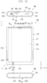
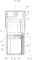
- FIGS. 2A and 2B are diagrams illustrating front and rear views of an electronic device in a slide-in state according to various embodiments of the present disclosure.
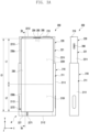
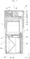
- FIGS. 3A and 3B are diagrams illustrating front and rear views of an electronic device in a slide-out state according to various embodiments of the present disclosure.
- the electronic device 200 of FIGS. 2A to 3B may be at least partially similar to the electronic device 101 of FIG. 1 or may further include other embodiments of the electronic device.
- the electronic device 200 may include a first housing 210; a second housing 220 coupled to the first housing 210 so that it can slide from the first housing 210 in a designated direction (e.g.,direction 1 or direction 2) (e.g., ⁇ y-axis direction); and a rollable display 230 (e.g., a flexible display, an expandable display or a stretchable display) disposed to be supported through at least a portion of the first housing 210 and the second housing 220.
- a designated direction e.g.,direction 1 or direction 2
- a rollable display 230 e.g., a flexible display, an expandable display or a stretchable display
- the term “direction 1" or “1” may be understood or interpreted as a direction in which a display area of the rollable display 230 is expanded, and the term “direction 2" or “2” may be understood or interpreted as i) a direction in which a display area of the rollable display 230 is reduced or ii) a direction opposite to the direction 1.
- the electronic device 200 may be configured to slide out the second housing 220 in a first direction (direction 1) based on the first housing 210 gripped by the user, or slide in the second housing 220 in a second direction (direction 2) opposite to the first direction (direction 1).
- the electronic device 200 may be switched to a slide-in state by at least a portion of the second housing 220 including the second space 2201 being accommodated in the first space 2101 of the first housing 210.
- the electronic device 200 may include a support member (e.g., the support member 240 of FIG. 4 ) (e.g., a bendable member, an articulated hinge module, or a multi-bar assembly) forming at least partially the same plane as at least a portion of the second housing 220 in a slide-out state and being accommodated at least partially in the first space 2101 of the first housing 210 in a slide-in state.
- a support member e.g., the support member 240 of FIG. 4
- a bendable member, an articulated hinge module, or a multi-bar assembly forming at least partially the same plane as at least a portion of the second housing 220 in a slide-out state and being accommodated at least partially in the first space 2101 of the first housing 210 in a slide-in state.
- At least a portion of the rollable display 230 may be disposed invisible from the outside in a slide-in state by being supported by a support member (e.g., the support member 240 of FIG. 4 ) and being accommodated in the first space 2101 of the first housing 210.
- at least a portion of the rollable display 230 may be disposed to be visible from the outside in a slide-out state by being supported by a support member (e.g., the support member 240 of FIG. 4 ) forming at least partially the same plane as at least a portion of the second housing 220 and being accommodated in the first space 2101 in a bent manner.
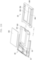
- the electronic device 200 may include a first housing 210 that includes a first lateral member 211 and a second housing 220 that includes a second lateral member 221.
- the first lateral member 211 may include a first side surface 2111 having a first length along a first direction (e.g., the y-axis direction); a second side surface 2112 extending to have a second length shorter than the first length along a direction (e.g., the x-axis direction) substantially perpendicular to the first side surface 2111; and a third side surface 2113 extending substantially parallel to the first side surface 2111 from the second side surface 2112 and having the first length.
- the first lateral member 211 may be at least partially formed of a conductive member (e.g., metal). In some embodiments, the first lateral member 211 may be formed by combining a conductive member and a non-conductive member (e.g., polymer). According to an embodiment, the first housing 210 may include a first extension member 212 extending from at least a portion of the first lateral member 211 to at least a portion of the first space 2101. According to an embodiment, the first extension member 212 may be integrally formed with the first lateral member 211. In some embodiments, the first extension member 212 may be formed separately from the first lateral member 211 and structurally combined with the first lateral member 211.
- a conductive member e.g., metal
- the first lateral member 211 may be formed by combining a conductive member and a non-conductive member (e.g., polymer).
- the first housing 210 may include a first extension member 212 extending from at least a portion of the first lateral member
- the second lateral member 221 may include a fourth side surface 2211 that at least partially corresponds to the first side surface 211 and has a third length; a fifth side surface 2212 that extends substantially parallel to the second side surface 2112 from the fourth side surface 2211and has a fourth length shorter than the third length; and a sixth side surface 2213 that extends from the fifth side surface2212 to correspond to the third side surface 2113 and has the third length.
- the second lateral member 221 may be at least partially formed of a conductive member (e.g., metal).
- the second lateral member 221 may be formed by combining a conductive member and a non-conductive member (e.g., polymer).
- the second lateral member 221 may include a second extension member 222 extending to at least a portion of the second space 2201 of the second housing 220.
- the second extension member 222 may be integrally formed with the second lateral member 221.
- the second extension member 222 may be formed separately from the second lateral member 221 and structurally combined with the second lateral member 221.
- the first side surface 2111 and the fourth side surface 2211 may be slidably coupled to each other.
- the third side surface 2113 and the sixth side surface 2213 may be slidably coupled to each other.
- the fourth side surface 2211 may be disposed to be substantially invisible from the outside by being overlapped with the first side surface 2111.
- the sixth side surface 2213 may be disposed to be substantially invisible from the outside by being overlapped with the third side surface 2113.
- at least a portion of the fourth side surface 2211 and the sixth side surface 2213 may be disposed to be at least partially visible from the outside in a slide-in state.
- the second extension member 222 may be disposed to be substantially invisible from the outside by being overlapped with the first extension member 212.
- the first housing 210 may include a first rear surface cover 213 coupled to at least a portion of the first lateral member 211.
- the first rear surface cover 213 may be disposed in a manner coupled with at least a portion of the first extension member 212.
- the first rear surface cover 213 may be integrally formed with the first lateral member 211.
- the first rear surface cover 213 may be formed of polymer, coated or tinted glass, ceramic, metal (e.g., aluminum, stainless steel (STS), or magnesium), or a combination of at least two of these materials.
- the first rear surface cover 213 may be extended to at least a portion of the first lateral member 211.
- at least a portion of the first extension member 212 may be replaced with the first rear surface cover 213.
- the second housing 220 may include a second rear surface cover 223 coupled to at least a portion of the second lateral member 221.
- the second rear surface cover 223 may be disposed in a manner in which it is coupled with at least a portion of the second extension member 222.
- the second rear surface cover 223 may be integrally formed with the second lateral member 221.
- the second rear surface cover 223 may be formed of polymer, coated or tinted glass, ceramic, metal (e.g., aluminum, stainless steel (STS), or magnesium), or a combination of at least two of these materials.
- the second rear surface cover 223 may be extended to at least a portion of the second lateral member 221.
- at least a portion of the second extension member 222 may be replaced with a second rear surface cover 223.
- the electronic device 200 may include a rollable display 230 disposed to be supported by at least a portion of the first housing 210 and the second housing 220.
- the rollable display 230 may include a first portion 230a (e.g., a flat portion) that is always visible from the outside and a second portion 230b (e.g., a bendable portion) that extends from the first portion 230a and is at least partially accommodated in the first space 2101 of the first housing 210 to be invisible from the outside in a slide-in state.
- the first portion 230a may be disposed to be supported by the second housing 220, and the second portion 230b may be at least partially supported by a support member (e.g.,the support member 240 of FIG. 4 ).
- the second portion 230b of the rollable display 230 may be disposed so that it can extend from the first portion 230a while being supported by the support member (e.g., the support member 240 of FIG. 4 ), form substantially the same plane as the first portion 230a, and be visible from the outside in a state that the second housing 220 slides out along the first direction (direction 1).
- the second portion 230b of the rollable display 230 may be disposed so that it can be accommodated in a manner of being bent into a first space 2101 of the first housing 210 and be invisible from the outside in a state that the second housing 220 slides in along the second direction (direction 2). Accordingly, the electronic device 200 may vary the display area of the rollable display in accordance with the second housing 220 moving in a sliding manner along a designated direction (e.g., the ⁇ y-axis direction) from the first housing 210.
- a designated direction e.g., the ⁇ y-axis direction
- the rollable display 230 may vary the length in a first direction (direction 1) in accordance with the sliding movement of the second housing 220 moving relative to the first housing 210.
- the rollable display 230 may have a first display area (e.g., an area corresponding to the first portion 230a) corresponding to the first length L1.
- the rollable display 230 in the slide-out state, may be extended to correspond to the third length L3 longer than the first length L1 and have the third display area (e.g., the area including the first portion 230a and the second portion 230b) larger than the first display area in accordance with the sliding movement of the second housing 220 additionally moved by a second length L2 relative to the first housing 210.
- the third display area e.g., the area including the first portion 230a and the second portion 230b
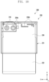
- the electronic device 200 may include at least one of an input device (e.g., a microphone 203-1) disposed in the second space 2201 of the second housing 220, an audio output device (e.g., a receiver 206 and/or a speaker 207 for a call), a sensor module 204 and 217, a camera module (e.g., a first camera module 205 or a second camera module 216), a connector port 208, a key input device 219, or an indicator (not shown).
- the electronic device 200 may include another input device (e.g., a microphone 203) disposed in the first housing 210.
- the electronic device 200 may be configured so that at least one of the above-described components is omitted or other components are additionally included. In another embodiment, at least one of the above-described components may be disposed in the first space 2101 of the first housing 210.
- the input device may include a microphone 203-1.
- the input device e.g., the microphone 203-1) may include a plurality of microphones disposed to detect the direction of sound.
- the audio output device may include, for example, a receiver 206 and a speaker 207 for a call.
- the speaker 207 may correspond to the outside through at least one speaker hole formed in the second housing 220 in a position always exposed to the outside regardless of the slide-in/the slide-out state (e.g., the fifth side surface 2212).
- the connector port 208 may correspond to the outside through a connector port hole formed in the second housing 220 in a slide-out state.
- the connector port 208 may correspond to the outside through an opening formed in the first housing 210 and formed to correspond to the connector port hole.
- the receiver 206 for a call may include a speaker (e.g., a piezo speaker) operating while excluding a separate speaker hole.
- the sensor modules 204 and 217 may generate electrical signals or data values corresponding to an internal operating state of the electronic device 200 or an external environmental state.
- the sensor modules 204 and 217 may include, for example, the first sensor module 204 (e.g., a proximity sensor or an illuminance sensor) disposed on the front side of the electronic device 200 and/or the second sensor module 217 (e.g., a heart rate monitoring (HRM) sensor) disposed on the rear surface of the electronic device 200.
- the first sensor module 204 may be disposed below the rollable display 230 on the front side of the electronic device 200.
- the first sensor module 204 and/or the second sensor module 217 may include at least one of a proximity sensor, an illuminance sensor, a time of flight (TOF) sensor, an ultrasonic sensor, a fingerprint recognition sensor, a gesture sensor, a gyro sensor, an air pressure sensor, a magnetic sensor, an acceleration sensor, a grip sensor, a color sensor, an infrared (IR) sensor, a bio sensor, a temperature sensor, or a humidity sensor.
- the camera module may include a first camera module 205 disposed on the front side of the electronic device 200 and a second camera module 216 disposed on the rear surface of the electronic device 200.
- the electronic device 200 may include a flash (not shown) located near the second camera module 216.
- the camera modules 205 and 216 may include one or a plurality of lenses, an image sensor, and/or an image signal processor.
- the first camera module 205 may be disposed under the rollable display 230 and be configured to photograph a subject through a part of an active area (e.g., a display area) of the rollable display 230.
- the first camera module 205 among the camera modules and part of sensor module 204 among the sensor modules 204 and 217 may be disposed to detect the external environment through the rollable display 230.
- the first camera module 205 or part of the sensor module 204 may be disposed in the second space 2201 of the second housing 220 to be in contact with the external environment through a transparent area or a perforated opening formed in the rollable display 230.
- an area facing the first camera module 205 of the rollable display 230 may be formed as a transmissive area having a designated transmittance as a part of a display area displaying content.
- the transmissive area may be formed to have a transmittance in a range of about 5% to about 20%.
- a transmissive area may include an area overlapping an effective area (e.g., an angle of view area) of the first camera module 205 through which light for generating an image formed by an image sensor passes.
- the transmissive area of the rollable display 230 may include an area in which a pixel arrangement density and/or a wiring density are lower than the surrounding area.
- a transmissive area may replace the aforementioned opening.
- some types of camera module 205 may include an under display camera (UDC).
- UDC under display camera
- some types of sensor module 204 may be disposed to perform their function in the inner space of the electronic device 200 without being visually exposed through the rollable display 230.
- the electronic device 200 may include at least one antenna (e.g., the antenna 224b of FIG. 10 ) electrically connected to the wireless communication circuit (e.g., the wireless communication module 192 of FIG. 1 ) disposed in the second housing 220.
- the wireless communication circuit may be disposed in the first space 2101 of the first housing 210.
- the electronic device 200 may include a bezel antenna A disposed through the conductive first lateral member 211 of the first housing 210.
- the bezel antenna A may be disposed on at least a portion of the second side surface 2112 and the third side surface 2113 of the first lateral member 211, and it may include a conductive portion 227 electrically segmented through at least one segmentation portion 2271 and 2272 formed of a non-conductive material (e.g., polymer).
- the wireless communication circuit e.g., the wireless communication module 192 of FIG. 1
- the wireless communication circuit may be configured to transmit or receive the wireless signal in at least one frequency band (e.g., about 600 MHz to 9000 MHz) (e.g., the legacy band or NR band) designated through the conductive part 227.
- the electronic device 200 may be disposed in an inner space (e.g., the first space 2101 or the second space 2201), and it may include further at least one antenna module (e.g., a 5G antenna module or an antenna structure) disposed to transmit or receive the wireless signal in a frequency band ranging from 3GHz to 100GHz through another wireless communication circuit (e.g., the wireless communication module 192 of FIG. 1 ).
- an antenna module e.g., a 5G antenna module or an antenna structure
- a slide-in/a slide-out operation of the electronic device 200 may be automatically performed.
- the slide-in/the slide-out operation of the electronic device 200 may be performed through gear-coupling of a driving motor (e.g., the driving motor 260 of FIG. 4 ) including a pinion gear (e.g., the pinion gear 261 of FIG. 6A ) disposed in the second space 2201 of the second housing 220, with a rack gear (e.g., the rack gear 2251 of FIG. 4 ) disposed in the first space 2101 of the first housing 210 and gear-coupled with the pinion gear 261.
- the processor e.g., processor 120 of FIG.
- the electronic device 200 may operate a driving motor (e.g., the driving motor 260 of FIG. 4 ) disposed inside the electronic device 200 in the case of detecting a triggering operation to switch from a slide-in state to a slide-out state or to switch from a slide-out state to a slide-in state.
- the triggering operation may include selecting (e.g., touching) an object displayed on the rollable display 230 or manipulating a physical button (e.g., a key button) included in the electronic device 200.
- the electronic device 200 may provide an efficient electrical connection structure with the driving motor 260 by including electronic components (e.g., a board or a battery) disposed together with the driving motor 260 in the second space 2201 of the second housing 220.
- the operational reliability of the electronic device 200 may be helped to improve by the inclusion of a support structure disposed in the first space 2101 of the first housing 210 to support at least a portion of the rollable display 230 in a slide-out state.
- the support bracket 225 may include a support plate 2253 formed to support the rear surface of the support member 240 in a slide-out state by extending from at least a portion of the support part 2252 to at least a portion of the opening 225a.
- the support bracket 225 may include a rack gear 2251 fixed to cross the opening 225a and have a length along a direction parallel to the sliding direction.
- the rack gear 2251 may be integrally formed with the support bracket 225.
- the electronic device 200 may include a pair of guide rails 226 to guide both ends of the support member 240 in a sliding direction by being disposed on both sides of the support bracket 225.
- the first housing 210 in the first extension member 212, may include an opening 212a (e.g., a through hole) of FIG. 4 disposed in an area corresponding to the camera module 216 and/or the sensor module 217 disposed on the second housing 220 in the case that the electronic device 200 is in a slide-in state.
- the camera module 216 and/or the sensor module 217 in the case that the electronic device 200 is in a slide-in state, may detect the external environment through the opening 212a of FIG. 4 formed in the first housing 210.
- an area corresponding to at least the camera module 216 and/or the sensor module 217 of the first rear surface cover 213 may be processed to be transparent.
- the electronic device 200 may include a first printed circuit board 251 and an antenna member 253 disposed between the first extension member 212 and the first rear surface cover 213 in the first housing 210.
- the first printed circuit board 251 and the antenna member 253 may be disposed on at least a portion of the first extension member 212.
- the first printed circuit board 251 and the antenna member 253 may be electrically connected to the second printed circuit board 252 through at least one flexible printed circuit board (e.g., an electrical connection member, a flexible printed circuit board (FPCB) or a flexible RF cable (FRC)).
- the antenna member 253 may include a multi-function coil or multi-function core (MFC) antenna for performing a wireless charging function, a near field communication (NFC) function, and/or an electronic payment function.
- MFC multi-function coil or multi-function core
- NFC near field communication
- the antenna member 253 may be electrically connected to the second printed circuit board 252 through the first circuit board 251 by being connected to the first printed circuit board 251.
- FIG. 5A illustrates a cross-sectional view of an electronic device taken along line 5a-5a of FIG. 2A according to various embodiments of the present disclosure.
- FIG. 5B illustrates a cross-sectional view of an electronic device taken along line 5b-5b of FIG. 3A according to various embodiments of the present disclosure.
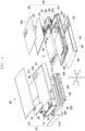
- the electronic device 200 may include a first housing 210 having a first space 2101; a second housing 220 having a second space 2201; a support member 240 slidably connected to the first housing 210 and at least partially accommodated in the first space 2101 in a slide-in state; a rollable display 230 disposed to receive support of at least a portion of the support member 240 and at least a portion of the second housing 220; and a driving motor 260 disposed in the second space 2201 and including a pinion gear (e.g., the pinion gear 261 of FIG. 6A ) gear-coupled toa rack gear (e.g.,the rack gear 2251 of FIG. 6A ) of the first space 2101.
- the driving motor 260 may move automatically the second housing 220 relative to the first housing 210 in a slide-in direction (direction 2) or in a slide-out direction (direction 1).
- the second housing 220 may transition to a slide-out state exposed to the outside at least partially from the first housing 210 along the first direction (direction 1) by driving the driving motor 260.
- the part slid into the first space 2101 may be at least partially exposed to the outside by the rollable display 230 being supported by the support bracket 225 in the slide-out state of the electronic device 200 (the state of FIG. 5B ) and moving together with the support member 240.
- the second display area of the rollable display 230 which is larger than the first display area, may be exposed to the outside.
- FIGS. 6a and 6b are diagrams illustrating a relationship of a slide stroke in accordance with a disposition of a driving motor in a slide-in/a slide-out state according to various embodiments of the present disclosure.
- the electronic device 200 may include a first housing 210 including a first space 2101 and a second housing 220 slidably coupled to the first housing 210.
- the second housing 220 may be disposed to be slid out, relative to the first housing 210, along the first direction (direction 1) (e.g., y-axis direction), or be slid in along the second direction (direction 2) (e.g., -y axis direction).
- the second housing 22 0 may be disposed to be slidable into a specified slide stroke in the up and down directions (e.g., ⁇ y axis direction) based on the first housing 210 gripped by the user.
- the second housing 220 may move along a rack gear 2251 having the same length and have a second slide stroke S2 shorter than the first slide stroke S1.
- the driving motor 260 is disposed at the lower end of the second housing 220, it may have a relatively extended slide stroke S1.
- the rack gear 2251 is disposed with a length substantially corresponding to the overall length of the first housing 210
- a third slide stroke S3 of the second housing 220 moving following this may be more extended than the first slide stroke S1.
- the electronic device 200 may help improve reliability and convenience of the electronic device by providing a user with a relatively expanded display area of the rollable display 230 in a slide-out state through an extension of the slide stroke.
- the electronic device 200 may include a first housing 210 including a first space 2101 and a second housing 220 slidably coupled to the first housing 210.
- the second housing 220 may be disposed to be slid out, relative to the first housing 210, along the first direction (direction 1) (e.g., y-axis direction), or be slid in along the second direction (direction 2) (e.g., -y axis direction).
- the electronic device 200 may include at least one electronic component disposed in the second space 2201 of the second housing 220. According to an embodiment, at least one electronic component may be disposed in a position provided through the second extension member 2222 in the second space 2201 of the second housing 220. According to an embodiment, at least one electronic component may include a second printed circuit board 252, a key button 219 (e.g., a key button including a fingerprint sensor) disposed around the second printed circuit board 252, a camera module 216, a socket module 218 (e.g., a SIM tray), a speaker 207, a connector port 208, or a battery B.
- a key button 219 e.g., a key button including a fingerprint sensor
- an efficient electrical connection may be possible because a plurality of electronic components are disposed around the second printed circuit board 252 in the second space 2201 of the second housing 220 together with the driving motor 260.
- the volume and the number of the flexible printed circuit board F1(e.g., FPCB) to be electrically connected to the second printed circuit board 252 may be relatively increased.
- the electronic device 200 may include a vibrator 270 (e.g., a vibration motor) disposed around the driving motor 260 in the second space 2201 of the second housing 220.
- the electronic device 200 may have one end electrically connected to the second printed circuit board 252 and the other end including a printed circuit board F1 that extends into the first space 2101 of the first housing 220.
- the other end of the flexible printed circuit board F1 may be electrically connected to the first printed circuit board (e.g., the first printed circuit board 251 of FIG. 4 ) and/or the antenna member (e.g., the antenna member 253 of FIG. 4 ) after penetrating at least one of the side surfaces (e.g., the first side surface and/or the third side surface of FIG. 2A ).
- the flexible printed circuit board F1 may electrically connect the second printed circuit board 252 to the first printed circuit board 251 and/or the antenna member 253.
- the flexible printed circuit board F1 may be disposed to have a length or a shape capable of accommodating the slide stroke of the electronic device 200.
- the flexible printed circuit board F1 may be formed of a material or in a shape having elasticity that expands in a slide-out state and returns to its original position in a slide-in state.
- the flexible printed circuit board F1 may include a flexible printed circuit board (FPCB) or a flexible RF cable (FRC).
- FIGS. 8A and 8B are configuration diagrams of an electronic device illustrating a disposition structure of an antenna member and a first printed circuit board according to various embodiments of the present disclosure.
- the electronic device 200 may include a first printed circuit board 251 and an antenna member 253 disposed in a space between the first extension member 212 and the first rear surface cover 213.
- the antenna member 253 may include a coil member disposed through a dielectric film.
- the antenna member 253 may include a multi-function coil or multi-function core (MFC) antenna for performing a wireless charging function, a near field communication (NFC) function, and/or an electronic payment function.
- the first printed circuit board 251 may be disposed in a manner to be electrically connected to the flexible printed circuit board (the flexible printed circuit board F1 of FIG.
- the antenna member 253 also may be disposed in a manner to be electrically connected to the flexible printed circuit board disposed in the first space 2101 after the connector part 253a extending from the antenna member 253 is penetrated through the first through hole 210a.
- the first printed circuit board 251 and the antenna member 253 may be disposed to be electrically connected to the flexible printed circuit board F1 in the first space 2101 after being penetrated through different respective through holes disposed on the first extension member 212.
- the electronic device 200 may include a microphone 203 as an input device that extends from the first printed circuit board 2511 and is disposed through the second through hole 210b formed in the second side surface 2112 of the first housing 210.
- the first housing 210 may include a third through hole 210c disposed on the first side surface2111 and/or the third side surface2113.
- the third through hole 210c may be used as a fastening path to fasten a guide rail (e.g., the guide rail 226 of FIG. 4 ) toa support bracket (e.g., the support bracket 225 of FIG. 4 ) through a fastening member such as a screw through the third through hole 210c by being formed in a manner to connect the first space 2101 from the outside.
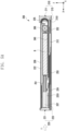
- FIG. 9 illustrates a cross-sectional view of an electronic device including a guide structure according to various embodiments of the present disclosure.
- the electronic device 200 may include a support member 240 for supporting the rollable display 230 and a pair of guide rails 226 for guiding both ends of the support member 240.
- the support member 240 may include a plurality of multi-bars 241 rotatably coupled to each other and guide protrusions 2411 protruding from both ends of each of the multi-bars 241.
- the guide rail 226 may be fixed to both side surfaces of the support bracket 225 disposed in the first space 2101 of the first housing 210.
- the guide rail 226 may include a guide slit 2261 formed at a position corresponding to the movement trajectory of the support member 240.
- FIG. 10 illustrates a configuration diagram of an electronic device including a rear bracket according to various embodiments of the present disclosure.
- the second housing 220 may include a rear bracket 224 disposed between the second extension member 222 and the second rear surface cover (e.g., the second rear surface cover223 of FIG. 4 ).
- the rear bracket 224 may be disposed in a manner that it is coupled with at least a portion of the second extension member 222.
- the rear bracket 224 in the case that the rear bracket 224 is formed of an injection product (e.g., an antenna carrier) of a dielectric material, it may include at least one antenna element 224b disposed on an outer surface.
- at least one antenna element 224b may include a laser direct structuring (LDS) antenna pattern formed on an outer surface of the rear bracket 224.
- LDS laser direct structuring
- At least one antenna element 224b may include a conductive plate attached to the outer surface of the rear bracket 224, or a conductive paint or conductive pattern formed on the outer surface. In some embodiments, at least one antenna element 224b may be disposed in an embedded manner in the case that the rear bracket 224 is ejected. According to an embodiment, at least one antenna element 224b may beconfigured to transmit or receive radio signals in a designated frequency band (e.g., the legacy band) by being electrically connected to a wireless communication circuit (e.g., the wireless communication module 192 of FIG. 1 ) disposed on the second printed circuit board 252.
- a wireless communication circuit e.g., the wireless communication module 192 of FIG. 1
- FIGS. 11A and 11B are diagrams illustrating a support structure for a rollable display according to various embodiments of the present disclosure.
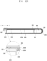
- FIG. 12A is a cross-sectional view illustrating a coupled state of a first housing and a support bracket in a slide-in state as viewed along line 12a-12a of FIG. 11B according to various embodiments of the present disclosure.
- FIG. 12B is a cross-sectional view illustrating a coupled state of the first housing and the support bracket in a slide-out state according to various embodiments of the present disclosure.
- the electronic device 200 may include a display support structure configured to support at least a portion of the support member 240 in a slide-out state.
- the second housing 220 may include a first recess 2221 formed in the second extension member 222 and a second recess 2222 formed in the first recess 2221.
- the first recess 2221 and the second recess 2222 may be formed as open in the direction of one edge (e.g., the edge in the direction of the support bracket) of the second extension member 222.
- the second housing 220 may include a support cover 2223 attached to the first recess 2221 in the second extension member 222.
- the support cover 2223 in the case that the support cover 2223 is attached to the first recess 2221, it may support without deterioration in surface quality of the rollable display 230 by forming substantially the same plane as the outer surface of the second extension member 222.
- the support bracket 225 may include a support plate 2253 extending from the support part 2252 to the opening 225a.
- the support plate 2253 may have a coupling structure slidably accommodated in the space between the support cover 2223 and the second recess 2222.
- the support plate 2253 may help improve the surface quality of the rollable display 230 by supporting the rear surface of the support member 240 to reduce the sagging of the support member 240 through the opening 225a in the slide-out state.
- the support cover 2223 may support the rollable display 230 without bends or steps by forming the same plane as the support member 240 even in a slide-out state through being formed to have substantially the same thickness as that of the support member 240.
Landscapes
- Engineering & Computer Science (AREA)
- Theoretical Computer Science (AREA)
- Signal Processing (AREA)
- Computer Hardware Design (AREA)
- Physics & Mathematics (AREA)
- Human Computer Interaction (AREA)
- General Engineering & Computer Science (AREA)
- General Physics & Mathematics (AREA)
- Computer Networks & Wireless Communication (AREA)
- Mathematical Physics (AREA)
- Power Engineering (AREA)
- Telephone Set Structure (AREA)
Claims (12)
- Elektronische Vorrichtung, die Folgendes umfasst:ein erstes Gehäuse;ein zweites Gehäuse, das mit dem ersten Gehäuse verschiebbar gekoppelt ist;ein rollbares Display, das so angeordnet ist, dass es von dem ersten Gehäuse und dem zweiten Gehäuse gestützt wird und dessen Anzeigebereich basierend auf dem Einschubzustand oder dem Ausschubzustand des zweiten Gehäuses verkleinert oder vergrößert wird;ein Stützelement, das auf einer Rückseite des rollbaren Displays angeordnet ist, um zumindest einen Teil des rollbaren Displays zu stützen;eine erste Leiterplatte und ein Zahnstangengetriebe, die in dem ersten Gehäuse angeordnet sind;eine zweite Leiterplatte, die in dem zweiten Gehäuse angeordnet ist; undeine flexible Leiterplatte, die so konfiguriert ist, dass sie die erste Leiterplatte und die zweite Leiterplatte verbindet, und die so konfiguriert ist, dass sie basierend auf dem Einschubzustand oder dem Ausschubzustand des zweiten Gehäuses gefaltet oder entfaltet werden kann;wobei das zweite Gehäuse ferner Folgendes umfasst:einen Antriebsmotor, der so konfiguriert ist, dass er eine Antriebskraft zum Antreiben des zweiten Gehäuses bereitstellt, und an einer Kante des zweiten Gehäuses angeordnet ist, die einem unteren Teil der elektronischen Vorrichtung in dem Einschubzustand entspricht;eine Batterie, die so konfiguriert ist, dass sie den Antriebsmotor mit Leistung versorgt; undein Ritzel, das so konfiguriert ist, dass es Leistung basierend auf der Antriebskraft des Antriebsmotors überträgt und mit dem Zahnstangengetriebe zahnradgekoppelt ist.
- Elektronische Vorrichtung nach Anspruch 1, wobei ein Schiebehub des zweiten Gehäuses entsprechend einer Dispositionslänge des Zahnstangengetriebes bestimmt wird.
- Elektronische Vorrichtung nach einem der Ansprüche 1 oder 2, wobei die Batterie mit der zweiten Leiterplatte elektrisch verbunden ist.
- Elektronische Vorrichtung nach einem der vorhergehenden Ansprüche, wobei das Zahnstangengetriebe so angeordnet ist, dass es eine Länge in einer Richtung parallel zu der ersten Richtung aufweist.
- Elektronische Vorrichtung nach Anspruch 1, wobei die elektronische Vorrichtung ferner mindestens eine elektronische Komponente enthält, die mindestens ein Kameramodul, einen Lautsprecher, ein Mikrofon, ein Steckdosenmodul, ein Anschlussmodul, einen Tastenknopf und/oder mindestens ein Sensormodul enthält.
- Elektronische Vorrichtung nach Anspruch 1, wobeidas erste Gehäuse ferner einen ersten Raum enthält, der durch ein erstes seitliches Element gebildet wird;das zweite Gehäuse ferner einen zweiten Raum enthält, der durch ein zweites seitliches Element gebildet wird;
- Elektronische Vorrichtung nach einem der vorhergehenden Ansprüche, wobei die elektronische Vorrichtung ferner ein Antennenelement enthält.
- Elektronische Vorrichtung nach einem der vorhergehenden Ansprüche, wobei die erweiterbare flexible Leiterplatte ein flexibles RF-Kabel, FRC, enthält.
- Elektronische Vorrichtung nach Anspruch 6, die ferner Folgendes umfasst:ein erstes Verlängerungselement, das sich von dem ersten seitlichen Element bis zu dem ersten Raum erstreckt; undeine Stützhalterung, die in dem ersten Raum angeordnet ist;wobei die Stützhalterung einen Stützteil, dessen äußere Oberfläche in einer Kurve ausgebildet ist, um zumindest einen Teil des Stützelements zu stützen, und eine Stützplatte enthält, die sich von dem Stützteil in Richtung des zweiten Gehäuses erstreckt, wobei die Stützplatte so ausgebildet ist, dass sie zumindest einen Teil des Stützelements in dem Ausschubzustand stützt.
- Elektronische Vorrichtung nach Anspruch 9, wobei die Stützplatte mit zumindest einem Teil eines zweiten Verlängerungselements, das sich von dem zweiten seitlichen Element bis zu dem zweiten Raum erstreckt, verschiebbar gekoppelt ist.
- Elektronische Vorrichtung nach Anspruch 10, wobei das zweite Verlängerungselement mindestens eine Aussparung zum Aufnehmen der Stützplatte und eine Stützabdeckung enthält, die die mindestens eine Aussparung abdeckt, um dieselbe Ebene wie eine äußere Oberfläche der Stützplatte zu bilden, wobei die Stützplatte in einem Raum zwischen der mindestens einen Aussparung und der Stützabdeckung in dem Einschubzustand aufgenommen ist.
- Elektronische Vorrichtung nach Anspruch 11, wobei die Stützabdeckung so ausgebildet ist, dass sie eine Dicke aufweist, die dieselbe wie die des Stützelements in dem Ausschubzustand ist.
Applications Claiming Priority (3)
| Application Number | Priority Date | Filing Date | Title |
|---|---|---|---|
| KR20220030574 | 2022-03-11 | ||
| KR1020220082103A KR20230133738A (ko) | 2022-03-11 | 2022-07-04 | 구동 모터를 포함하는 전자 장치 |
| PCT/KR2023/002374 WO2023171936A1 (ko) | 2022-03-11 | 2023-02-20 | 구동 모터를 포함하는 전자 장치 |
Publications (3)
| Publication Number | Publication Date |
|---|---|
| EP4270909A1 EP4270909A1 (de) | 2023-11-01 |
| EP4270909A4 EP4270909A4 (de) | 2024-06-12 |
| EP4270909B1 true EP4270909B1 (de) | 2025-06-25 |
Family
ID=87155612
Family Applications (1)
| Application Number | Title | Priority Date | Filing Date |
|---|---|---|---|
| EP23706982.8A Active EP4270909B1 (de) | 2022-03-11 | 2023-02-20 | Elektronische vorrichtung mit antriebsmotor |
Country Status (3)
| Country | Link |
|---|---|
| US (1) | US20240340367A1 (de) |
| EP (1) | EP4270909B1 (de) |
| WO (1) | WO2023171936A1 (de) |
Family Cites Families (8)
| Publication number | Priority date | Publication date | Assignee | Title |
|---|---|---|---|---|
| JP4094420B2 (ja) * | 2002-12-25 | 2008-06-04 | 京セラ株式会社 | フレキシブル配線基板およびこれを用いた携帯型電子機器 |
| KR101107127B1 (ko) * | 2010-01-12 | 2012-01-31 | 주식회사 다이아벨 | 이동 단말기 |
| US8711566B2 (en) * | 2011-09-02 | 2014-04-29 | Microsoft Corporation | Expandable mobile device |
| KR102389189B1 (ko) * | 2017-11-29 | 2022-04-22 | 삼성전자주식회사 | 확장가능한 디스플레이 영역을 갖는 플렉시블 디스플레이를 구비한 전자 장치 |
| KR102458690B1 (ko) * | 2018-04-04 | 2022-10-25 | 삼성전자주식회사 | 무선 충전 모듈 및 플렉서블 디스플레이를 포함하는 전자 장치 |
| KR102771862B1 (ko) * | 2019-04-05 | 2025-02-25 | 엘지전자 주식회사 | 롤-슬라이드 이동 단말기 |
| CN113068336A (zh) * | 2019-12-16 | 2021-07-02 | Oppo广东移动通信有限公司 | 电子装置 |
| WO2023182830A1 (ko) * | 2022-03-25 | 2023-09-28 | 삼성전자 주식회사 | 이물 유입 방지 구조를 포함하는 슬라이더블 전자 장치 |
-
2023
- 2023-02-20 EP EP23706982.8A patent/EP4270909B1/de active Active
- 2023-02-20 WO PCT/KR2023/002374 patent/WO2023171936A1/ko not_active Ceased
-
2024
- 2024-06-18 US US18/746,875 patent/US20240340367A1/en active Pending
Also Published As
| Publication number | Publication date |
|---|---|
| WO2023171936A1 (ko) | 2023-09-14 |
| EP4270909A4 (de) | 2024-06-12 |
| US20240340367A1 (en) | 2024-10-10 |
| EP4270909A1 (de) | 2023-11-01 |
Similar Documents
| Publication | Publication Date | Title |
|---|---|---|
| US12418098B2 (en) | Antenna and electronic device including the same | |
| US12443223B2 (en) | Flexible display and electronic device including same | |
| US12537418B2 (en) | Electronic device comprising drive motor | |
| US20250107022A1 (en) | Electronic device including rack gear guide structure | |
| EP4246714A1 (de) | Antenne und elektronische vorrichtung damit | |
| EP4375791B1 (de) | Elektronische vorrichtung mit antriebsmotor | |
| US20250008011A1 (en) | Electronic apparatus including antenna | |
| US20240422925A1 (en) | Electronic device comprising driving motor | |
| KR20230133739A (ko) | 구동 모터를 포함하는 전자 장치 | |
| US12422886B2 (en) | Electronic device including drive motor | |
| EP4270909B1 (de) | Elektronische vorrichtung mit antriebsmotor | |
| US20250227171A1 (en) | Electronic device comprising driving motor | |
| US20250267804A1 (en) | Electronic device comprising driving motor | |
| US12469972B2 (en) | Electronic device comprising antenna | |
| EP4580168A1 (de) | Elektronische vorrichtung mit antriebsmotor | |
| US20250053204A1 (en) | Flexible display assembly and electronic device including same | |
| US20250310430A1 (en) | Electronic device comprising retainer | |
| EP4485693A1 (de) | Elektronische vorrichtung mit antennenelement | |
| EP4572547A1 (de) | Wasserdichte struktur und elektronische vorrichtung mit wasserdichter struktur | |
| KR20230133738A (ko) | 구동 모터를 포함하는 전자 장치 | |
| CN118923000A (zh) | 包括天线的电子装置 | |
| CN118891787A (zh) | 包括天线的电子设备 | |
| KR20240176734A (ko) | 구동 모터를 포함하는 전자 장치 | |
| KR20250046100A (ko) | 랙 기어 가이드 구조를 포함하는 전자 장치 | |
| CN120936967A (zh) | 包括磁体的可卷曲电子装置 |
Legal Events
| Date | Code | Title | Description |
|---|---|---|---|
| STAA | Information on the status of an ep patent application or granted ep patent |
Free format text: STATUS: UNKNOWN |
|
| STAA | Information on the status of an ep patent application or granted ep patent |
Free format text: STATUS: THE INTERNATIONAL PUBLICATION HAS BEEN MADE |
|
| PUAI | Public reference made under article 153(3) epc to a published international application that has entered the european phase |
Free format text: ORIGINAL CODE: 0009012 |
|
| STAA | Information on the status of an ep patent application or granted ep patent |
Free format text: STATUS: REQUEST FOR EXAMINATION WAS MADE |
|
| 17P | Request for examination filed |
Effective date: 20230306 |
|
| AK | Designated contracting states |
Kind code of ref document: A1 Designated state(s): AL AT BE BG CH CY CZ DE DK EE ES FI FR GB GR HR HU IE IS IT LI LT LU LV MC ME MK MT NL NO PL PT RO RS SE SI SK SM TR |
|
| A4 | Supplementary search report drawn up and despatched |
Effective date: 20240513 |
|
| RIC1 | Information provided on ipc code assigned before grant |
Ipc: H02K 7/116 20060101ALI20240506BHEP Ipc: H05K 1/14 20060101ALI20240506BHEP Ipc: H01Q 1/24 20060101ALI20240506BHEP Ipc: G06F 1/16 20060101ALI20240506BHEP Ipc: H04M 1/02 20060101AFI20240506BHEP |
|
| GRAP | Despatch of communication of intention to grant a patent |
Free format text: ORIGINAL CODE: EPIDOSNIGR1 |
|
| STAA | Information on the status of an ep patent application or granted ep patent |
Free format text: STATUS: GRANT OF PATENT IS INTENDED |
|
| INTG | Intention to grant announced |
Effective date: 20250225 |
|
| GRAS | Grant fee paid |
Free format text: ORIGINAL CODE: EPIDOSNIGR3 |
|
| GRAA | (expected) grant |
Free format text: ORIGINAL CODE: 0009210 |
|
| STAA | Information on the status of an ep patent application or granted ep patent |
Free format text: STATUS: THE PATENT HAS BEEN GRANTED |
|
| DAV | Request for validation of the european patent (deleted) | ||
| DAX | Request for extension of the european patent (deleted) | ||
| AK | Designated contracting states |
Kind code of ref document: B1 Designated state(s): AL AT BE BG CH CY CZ DE DK EE ES FI FR GB GR HR HU IE IS IT LI LT LU LV MC ME MK MT NL NO PL PT RO RS SE SI SK SM TR |
|
| REG | Reference to a national code |
Ref country code: GB Ref legal event code: FG4D |
|
| REG | Reference to a national code |
Ref country code: CH Ref legal event code: EP |
|
| REG | Reference to a national code |
Ref country code: CH Ref legal event code: EP |
|
| REG | Reference to a national code |
Ref country code: IE Ref legal event code: FG4D |
|
| REG | Reference to a national code |
Ref country code: DE Ref legal event code: R096 Ref document number: 602023004335 Country of ref document: DE |
|
| REG | Reference to a national code |
Ref country code: NL Ref legal event code: FP |
|
| PG25 | Lapsed in a contracting state [announced via postgrant information from national office to epo] |
Ref country code: FI Free format text: LAPSE BECAUSE OF FAILURE TO SUBMIT A TRANSLATION OF THE DESCRIPTION OR TO PAY THE FEE WITHIN THE PRESCRIBED TIME-LIMIT Effective date: 20250625 |
|
| REG | Reference to a national code |
Ref country code: LT Ref legal event code: MG9D |
|
| PG25 | Lapsed in a contracting state [announced via postgrant information from national office to epo] |
Ref country code: GR Free format text: LAPSE BECAUSE OF FAILURE TO SUBMIT A TRANSLATION OF THE DESCRIPTION OR TO PAY THE FEE WITHIN THE PRESCRIBED TIME-LIMIT Effective date: 20250926 Ref country code: NO Free format text: LAPSE BECAUSE OF FAILURE TO SUBMIT A TRANSLATION OF THE DESCRIPTION OR TO PAY THE FEE WITHIN THE PRESCRIBED TIME-LIMIT Effective date: 20250925 |
|
| PG25 | Lapsed in a contracting state [announced via postgrant information from national office to epo] |
Ref country code: BG Free format text: LAPSE BECAUSE OF FAILURE TO SUBMIT A TRANSLATION OF THE DESCRIPTION OR TO PAY THE FEE WITHIN THE PRESCRIBED TIME-LIMIT Effective date: 20250625 |
|
| PG25 | Lapsed in a contracting state [announced via postgrant information from national office to epo] |
Ref country code: HR Free format text: LAPSE BECAUSE OF FAILURE TO SUBMIT A TRANSLATION OF THE DESCRIPTION OR TO PAY THE FEE WITHIN THE PRESCRIBED TIME-LIMIT Effective date: 20250625 |
|
| PG25 | Lapsed in a contracting state [announced via postgrant information from national office to epo] |
Ref country code: RS Free format text: LAPSE BECAUSE OF FAILURE TO SUBMIT A TRANSLATION OF THE DESCRIPTION OR TO PAY THE FEE WITHIN THE PRESCRIBED TIME-LIMIT Effective date: 20250925 |
|
| PG25 | Lapsed in a contracting state [announced via postgrant information from national office to epo] |
Ref country code: LV Free format text: LAPSE BECAUSE OF FAILURE TO SUBMIT A TRANSLATION OF THE DESCRIPTION OR TO PAY THE FEE WITHIN THE PRESCRIBED TIME-LIMIT Effective date: 20250625 |
|
| PG25 | Lapsed in a contracting state [announced via postgrant information from national office to epo] |
Ref country code: PT Free format text: LAPSE BECAUSE OF FAILURE TO SUBMIT A TRANSLATION OF THE DESCRIPTION OR TO PAY THE FEE WITHIN THE PRESCRIBED TIME-LIMIT Effective date: 20251027 |
|
| REG | Reference to a national code |
Ref country code: AT Ref legal event code: MK05 Ref document number: 1807836 Country of ref document: AT Kind code of ref document: T Effective date: 20250625 |
|
| PG25 | Lapsed in a contracting state [announced via postgrant information from national office to epo] |
Ref country code: IS Free format text: LAPSE BECAUSE OF FAILURE TO SUBMIT A TRANSLATION OF THE DESCRIPTION OR TO PAY THE FEE WITHIN THE PRESCRIBED TIME-LIMIT Effective date: 20251025 |
|
| PG25 | Lapsed in a contracting state [announced via postgrant information from national office to epo] |
Ref country code: AT Free format text: LAPSE BECAUSE OF FAILURE TO SUBMIT A TRANSLATION OF THE DESCRIPTION OR TO PAY THE FEE WITHIN THE PRESCRIBED TIME-LIMIT Effective date: 20250625 Ref country code: SM Free format text: LAPSE BECAUSE OF FAILURE TO SUBMIT A TRANSLATION OF THE DESCRIPTION OR TO PAY THE FEE WITHIN THE PRESCRIBED TIME-LIMIT Effective date: 20250625 |
|
| PG25 | Lapsed in a contracting state [announced via postgrant information from national office to epo] |
Ref country code: CZ Free format text: LAPSE BECAUSE OF FAILURE TO SUBMIT A TRANSLATION OF THE DESCRIPTION OR TO PAY THE FEE WITHIN THE PRESCRIBED TIME-LIMIT Effective date: 20250625 |
|
| PG25 | Lapsed in a contracting state [announced via postgrant information from national office to epo] |
Ref country code: PL Free format text: LAPSE BECAUSE OF FAILURE TO SUBMIT A TRANSLATION OF THE DESCRIPTION OR TO PAY THE FEE WITHIN THE PRESCRIBED TIME-LIMIT Effective date: 20250625 |
|
| PG25 | Lapsed in a contracting state [announced via postgrant information from national office to epo] |
Ref country code: EE Free format text: LAPSE BECAUSE OF FAILURE TO SUBMIT A TRANSLATION OF THE DESCRIPTION OR TO PAY THE FEE WITHIN THE PRESCRIBED TIME-LIMIT Effective date: 20250625 |
|
| PG25 | Lapsed in a contracting state [announced via postgrant information from national office to epo] |
Ref country code: SK Free format text: LAPSE BECAUSE OF FAILURE TO SUBMIT A TRANSLATION OF THE DESCRIPTION OR TO PAY THE FEE WITHIN THE PRESCRIBED TIME-LIMIT Effective date: 20250625 |
|
| PG25 | Lapsed in a contracting state [announced via postgrant information from national office to epo] |
Ref country code: ES Free format text: LAPSE BECAUSE OF FAILURE TO SUBMIT A TRANSLATION OF THE DESCRIPTION OR TO PAY THE FEE WITHIN THE PRESCRIBED TIME-LIMIT Effective date: 20250625 |
|
| PGFP | Annual fee paid to national office [announced via postgrant information from national office to epo] |
Ref country code: NL Payment date: 20260121 Year of fee payment: 4 |