EP4579990A2 - Startsteuerungsschaltung, elektrowerkzeug und startsteuerungsverfahren dafür - Google Patents
Startsteuerungsschaltung, elektrowerkzeug und startsteuerungsverfahren dafür Download PDFInfo
- Publication number
- EP4579990A2 EP4579990A2 EP24221718.0A EP24221718A EP4579990A2 EP 4579990 A2 EP4579990 A2 EP 4579990A2 EP 24221718 A EP24221718 A EP 24221718A EP 4579990 A2 EP4579990 A2 EP 4579990A2
- Authority
- EP
- European Patent Office
- Prior art keywords
- circuit
- switch circuit
- battery pack
- switch
- terminal
- Prior art date
- Legal status (The legal status is an assumption and is not a legal conclusion. Google has not performed a legal analysis and makes no representation as to the accuracy of the status listed.)
- Pending
Links
Images



Classifications
-
- H—ELECTRICITY
- H02—GENERATION; CONVERSION OR DISTRIBUTION OF ELECTRIC POWER
- H02P—CONTROL OR REGULATION OF ELECTRIC MOTORS, ELECTRIC GENERATORS OR DYNAMO-ELECTRIC CONVERTERS; CONTROLLING TRANSFORMERS, REACTORS OR CHOKE COILS
- H02P1/00—Arrangements for starting electric motors or dynamo-electric converters
- H02P1/16—Arrangements for starting electric motors or dynamo-electric converters for starting dynamo-electric motors or dynamo-electric converters
- H02P1/18—Arrangements for starting electric motors or dynamo-electric converters for starting dynamo-electric motors or dynamo-electric converters for starting an individual DC motor
-
- H—ELECTRICITY
- H02—GENERATION; CONVERSION OR DISTRIBUTION OF ELECTRIC POWER
- H02J—ELECTRIC POWER NETWORKS; CIRCUIT ARRANGEMENTS OR SYSTEMS FOR SUPPLYING OR DISTRIBUTING ELECTRIC POWER; SYSTEMS FOR STORING ELECTRIC ENERGY
- H02J7/00—Circuit arrangements for charging or discharging batteries or for supplying loads from batteries
- H02J7/60—Circuit arrangements for charging or discharging batteries or for supplying loads from batteries including safety or protection arrangements
- H02J7/663—Circuit arrangements for charging or discharging batteries or for supplying loads from batteries including safety or protection arrangements using battery or load disconnect circuits
- H02J7/667—Circuit arrangements for charging or discharging batteries or for supplying loads from batteries including safety or protection arrangements using battery or load disconnect circuits disconnection of loads if battery is not under charge, e.g. in vehicle if engine is not running
-
- F—MECHANICAL ENGINEERING; LIGHTING; HEATING; WEAPONS; BLASTING
- F16—ENGINEERING ELEMENTS AND UNITS; GENERAL MEASURES FOR PRODUCING AND MAINTAINING EFFECTIVE FUNCTIONING OF MACHINES OR INSTALLATIONS; THERMAL INSULATION IN GENERAL
- F16P—SAFETY DEVICES IN GENERAL; SAFETY DEVICES FOR PRESSES
- F16P3/00—Safety devices acting in conjunction with the control or operation of a machine; Control arrangements requiring the simultaneous use of two or more parts of the body
- F16P3/001—Safety devices for guarding the human operator of punch presses or like machine tools performing an opening and closing travel
- F16P3/003—Safety devices for guarding the human operator of punch presses or like machine tools performing an opening and closing travel by application of a specific control arrangement, e.g. specific switching systems or two-hand control
-
- H—ELECTRICITY
- H01—ELECTRIC ELEMENTS
- H01M—PROCESSES OR MEANS, e.g. BATTERIES, FOR THE DIRECT CONVERSION OF CHEMICAL ENERGY INTO ELECTRICAL ENERGY
- H01M50/00—Constructional details or processes of manufacture of the non-active parts of electrochemical cells other than fuel cells, e.g. hybrid cells
- H01M50/20—Mountings; Secondary casings or frames; Racks, modules or packs; Suspension devices; Shock absorbers; Transport or carrying devices; Holders
- H01M50/247—Mountings; Secondary casings or frames; Racks, modules or packs; Suspension devices; Shock absorbers; Transport or carrying devices; Holders specially adapted for portable devices, e.g. mobile phones, computers, hand tools or pacemakers
-
- H—ELECTRICITY
- H01—ELECTRIC ELEMENTS
- H01M—PROCESSES OR MEANS, e.g. BATTERIES, FOR THE DIRECT CONVERSION OF CHEMICAL ENERGY INTO ELECTRICAL ENERGY
- H01M50/00—Constructional details or processes of manufacture of the non-active parts of electrochemical cells other than fuel cells, e.g. hybrid cells
- H01M50/50—Current conducting connections for cells or batteries
- H01M50/572—Means for preventing undesired use or discharge
- H01M50/574—Devices or arrangements for the interruption of current
-
- H—ELECTRICITY
- H02—GENERATION; CONVERSION OR DISTRIBUTION OF ELECTRIC POWER
- H02J—ELECTRIC POWER NETWORKS; CIRCUIT ARRANGEMENTS OR SYSTEMS FOR SUPPLYING OR DISTRIBUTING ELECTRIC POWER; SYSTEMS FOR STORING ELECTRIC ENERGY
- H02J7/00—Circuit arrangements for charging or discharging batteries or for supplying loads from batteries
- H02J7/855—Circuit arrangements for charging or discharging batteries or for supplying loads from batteries with circuits adapted for supplying loads from the battery
-
- H—ELECTRICITY
- H01—ELECTRIC ELEMENTS
- H01M—PROCESSES OR MEANS, e.g. BATTERIES, FOR THE DIRECT CONVERSION OF CHEMICAL ENERGY INTO ELECTRICAL ENERGY
- H01M2220/00—Batteries for particular applications
- H01M2220/30—Batteries in portable systems, e.g. mobile phone, laptop
-
- H—ELECTRICITY
- H02—GENERATION; CONVERSION OR DISTRIBUTION OF ELECTRIC POWER
- H02J—ELECTRIC POWER NETWORKS; CIRCUIT ARRANGEMENTS OR SYSTEMS FOR SUPPLYING OR DISTRIBUTING ELECTRIC POWER; SYSTEMS FOR STORING ELECTRIC ENERGY
- H02J2207/00—Details of circuit arrangements for charging or discharging batteries or supplying loads from batteries
- H02J2207/10—Control circuit supply, e.g. means for supplying power to the control circuit
-
- H—ELECTRICITY
- H02—GENERATION; CONVERSION OR DISTRIBUTION OF ELECTRIC POWER
- H02J—ELECTRIC POWER NETWORKS; CIRCUIT ARRANGEMENTS OR SYSTEMS FOR SUPPLYING OR DISTRIBUTING ELECTRIC POWER; SYSTEMS FOR STORING ELECTRIC ENERGY
- H02J2207/00—Details of circuit arrangements for charging or discharging batteries or supplying loads from batteries
- H02J2207/20—Charging or discharging characterised by the power electronics converter
Definitions
- Electric tools have numerous advantages over traditional manual tools, offering significant improvements in efficiency, quality, and safety. This has made them increasingly popular among both professionals and casual users.
- an electric chainsaw is a sophisticated device composed of four main components: a motor that provides power, a battery pack for energy, a circuit board for drive control, and a saw chain for performing the cutting action.
- the second switch circuit plays a critical role by outputting different voltage waveforms based on the timing of current flows. These waveforms signal the main control unit to issue specific drive commands. For instance, when the second switch circuit first receives current from the DC conversion circuit, it generates a first voltage waveform, prompting the main control unit to issue a first drive command. This mechanism ensures precise control over tool activation, reducing the risk of unintended operation.
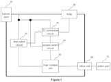
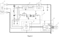
- the first switch circuit itself includes components such as a startup switch, a voltage dividing circuit, and a control switch. These components ensure that when the startup switch is closed and the battery pack is inserted, the control switch activates the DC conversion circuit, initiating the tool's operation. Additional safety measures, like a voltage regulator tube and a first protection diode, are included to stabilize the voltage and protect against electrical surges, further ensuring reliable performance.
- the second switch circuit includes parts like a capacitor and an optocoupler, which manage the timing of current flows. For example, when currents from the battery pack and the DC conversion circuit arrive simultaneously, the second switch circuit outputs a specific voltage waveform. Conversely, if one current arrives earlier, it outputs a different waveform. These distinct waveforms guide the main control unit in determining whether the tool should remain inactive or begin operation, adding a layer of safety and precision.
- a relay is incorporated into the apparatus. This relay, powered by the DC conversion circuit, connects the battery packto the drive unit, further controlling the flow of power. Additionally, a battery pack emergency warning circuit may be included to monitor temperature abnormalities. If an issue is detected, a backup battery can send an emergency alert to the user's device, ensuring quick response to potential hazards.
- Biometric authentication may also be employed to prevent accidental activation of control commands, adding a modern and secure dimension to tool management.
- the startup control circuit is integrated into power tools like chainsaws, pruners, and grass trimmers.
- the apparatus ensures that the tools operate only under specific conditions.
- the drive unit which controls the action part, responds to commands from the main control unit based on detected voltage waveforms, ensuring the tool's operation aligns with safe practices.
- the method of operation emphasizes timing and path differentiation of current flow.
- the timing differences produce specific waveforms. These waveforms guide the main control unit in determining whether to activate or restrict the tool's action part. This precise control ensures user safety and prevents accidental tool activation.
- the startup control circuit exemplifies the integration of advanced control systems in power tools. By combining components like switch circuits, DC conversion circuits, and emergency mechanisms, it addresses the need for safer and more reliable operation. This approach reflects a commitment to innovation and user safety, making power tools more accessible and secure for diverse applications.
- the integration of a DC conversion circuit and switch circuits creates a highly controlled startup process for power tools.
- the DC conversion circuit converts power from the battery pack into a form suitable for the operation of other components.
- the first and second switch circuits then work in tandem to regulate the flow of current, ensuring that the power tool activates only under safe and intended conditions. For instance, the first switch circuit triggers the DC conversion circuit, while the second switch circuit processes the timing of current flow to generate appropriate voltage waveforms for the main control unit.
- the second switch circuit's reliance on timing differences between current paths demonstrates its sophisticated design.
- the use of components like capacitors and optocouplers allows it to detect whether currents from the battery pack and DC conversion circuit arrive simultaneously or at different times. This distinction is critical, as it determines whether the tool remains inactive or begins operation. Such a system prevents unintended startups, especially during battery insertion or improper handling.
- the emergency warning circuit can detect overheating in the battery pack and immediately notify the user through a backup battery-powered system.
- the apparatus can disconnect the battery pack or even physically shield it to prevent further damage. This multi-layered approach to safety reflects the apparatus's commitment to addressing both user convenience and operational risks.
- the startup control circuit also reflects broader trends in technological integration, as it merges traditional mechanical systems with advanced electronic controls. This synthesis creates a new standard for power tools, where safety and performance are prioritized alongside user convenience.
- the apparatus's ability to adapt to various tools, from lawn care equipment to construction tools, demonstrates its versatility and widespread applicability.
- the apparatus's ability to detect and respond to abnormal conditions underscores its focus on proactive safety measures.
- the apparatus minimizes risks associated with battery failure. This feature is particularly valuable for tools used in demanding environments, where uninterrupted operation and user safety are paramount.
- a notable feature of the apparatus is its incorporation of relays as a fail-safe mechanism. Relays provide an additional layer of control by acting as intermediaries between the power source and the tool's drive unit. Their ability to open or close circuits based on specific conditions ensures that the tool remains inactive unless all safety parameters are met. This is particularly critical for tools used in construction or landscaping, where accidental activation could lead to severe injuries.
- the startup control circuit also embodies a holistic approach to tool safety, incorporating both preventive and reactive safety mechanisms.
- the preventive measures such as voltage regulation and precise current timing, ensure that potential hazards are mitigated before they occur.
- reactive features like the emergency warning circuit and physical battery shielding provide an added layer of protection against unforeseen issues.
- the apparatus By optimizing the performance of the DC conversion circuit and reducing unnecessary power consumption, the apparatus not only enhances tool efficiency but also minimizes its environmental footprint. This aligns with the growing demand for eco-friendly solutions in modern technology, ensuring that tools equipped with the apparatus are both high-performing and environmentally responsible.
- the apparatus sets the stage for the integration of smart technologies into power tools.
- biometric authentication and wireless connectivity illustrate the potential for tools to become part of the broader Internet of Things (IoT) ecosystem.
- IoT Internet of Things
- This connectivity enables users to monitor, control, and troubleshoot their tools remotely, further enhancing their convenience and functionality. For example, a user could receive notifications about battery health or operational status on their smartphone, allowing for timely maintenance and extended tool life.
- the adaptability of the startup control circuit to a wide range of tools and tasks also underscores its versatility. Whether used in residential settings for gardening tools or in industrial environments for heavy-duty equipment, the apparatus provides consistent safety and performance enhancements. This universality reduces the need for tool-specific solutions, simplifying the user experience and promoting the apparatus as a cost-effective investment for various applications.
- the startup control circuit stands as a testament to the potential of merging advanced engineering with practical design. By addressing both the technical and user-oriented aspects of power tool operation, it achieves a balance that is rare in the industry. Its innovative features not only improve the safety and efficiency of power tools but also pave the way for future advancements, ensuring its relevance in an increasingly technology-driven world. In every sense, the apparatus is a cornerstone of modern tool innovation, setting a high standard for what power tools can achieve.
- the purpose of the invention is to provide a startup control circuit, a power tool, and a power tool startup control method that can prevent accidental activation of the action part when the battery pack is inserted improperly, thereby improving the safety of the power tool.
- the invention provides a startup control circuit for a power tool, wherein the startup control circuit comprises:
- a first switch circuit a DC conversion circuit, a main control unit, and a second switch circuit
- the second switch circuit is connected to the battery pack, the DC conversion circuit, and the main control unit, wherein based on different timing sequences of currents flowing from the battery pack and the DC conversion circuit reaching the second switch circuit, the second switch circuit outputs different voltage waveforms;
- the main control unit is configured to output a first drive command when receiving a first voltage waveform, wherein the first voltage waveform is a voltage waveform outputted by the second switch circuit when the second switch circuit first receives a current flowing from the DC conversion circuit.
- the main control unit is further configured to output a second drive command when receiving a second voltage waveform, wherein the second voltage waveform is a voltage waveform outputted by the second switch circuit when the second switch circuit simultaneously receives currents flowing from the battery pack and the DC conversion circuit.
- the first voltage waveform is a voltage waveform that changes from low to high
- the second voltage waveform is a voltage waveform that changes from high to flat
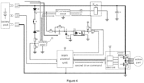
- the first switch circuit comprises a startup switch, a first resistor, a second resistor, and a control switch, wherein the first resistor and the second resistor form a voltage dividing circuit;
- the startup switch has a first terminal connected to a positive terminal of the battery pack, and a second terminal connected to ground through the voltage dividing circuit;
- the first switch circuit further comprises a voltage regulator tube, wherein the voltage regulator tube is connected between the startup switch and the voltage dividing circuit.
- the startup control circuit further comprises a first protection diode, wherein an anode of the first protection diode is connected to a positive terminal of the battery pack, and a cathode of the first protection diode is connected to the DC conversion circuit, the first switch circuit, and the second switch circuit.
- the second switch circuit comprises a first capacitor and an optocoupler, wherein a first terminal of the first capacitor is configured to receive current from the battery pack, and a second terminal of the first capacitor is connected to a first terminal of the optocoupler, wherein when a time of current flowing from the battery pack reaching the first terminal of the first capacitor is same as a time of current flowing from the DC conversion circuit reaching a second terminal of the optocoupler, the second switch circuit outputs the first voltage waveform;
- the second switch circuit When the time of current flowing from the battery pack reaching the first terminal of the first capacitor is earlier than the time of current flowing from the DC conversion circuit reaching the second terminal of the optocoupler, the second switch circuit outputs a second voltage waveform.
- the second switch circuit further comprises a second protection diode, wherein the second protection diode is connected to the first terminal of the optocoupler.
- the startup control circuit further comprises a relay, wherein the relay is connected in series between the positive terminal of the battery pack and the drive unit, wherein a coil of the relay is powered by the DC conversion circuit.
- the startup control circuit further comprises a second capacitor, wherein a first terminal of the second capacitor is connected to the relay and the drive unit, and a second terminal of the second capacitor is connected to ground.
- the drive unit controls the action part to work based on the second drive command.
Landscapes
- Engineering & Computer Science (AREA)
- Power Engineering (AREA)
- Electrochemistry (AREA)
- Chemical & Material Sciences (AREA)
- Chemical Kinetics & Catalysis (AREA)
- General Chemical & Material Sciences (AREA)
- General Engineering & Computer Science (AREA)
- Life Sciences & Earth Sciences (AREA)
- Biophysics (AREA)
- Computer Hardware Design (AREA)
- Mechanical Engineering (AREA)
- Charge And Discharge Circuits For Batteries Or The Like (AREA)
- Dc-Dc Converters (AREA)
Applications Claiming Priority (2)
| Application Number | Priority Date | Filing Date | Title |
|---|---|---|---|
| CN202323666567.6U CN221597730U (zh) | 2023-12-29 | 2023-12-29 | 启动控制电路及电动工具 |
| CN202311861721.7A CN120237982A (zh) | 2023-12-29 | 2023-12-29 | 启动控制电路、电动工具及电动工具启动控制方法 |
Publications (2)
| Publication Number | Publication Date |
|---|---|
| EP4579990A2 true EP4579990A2 (de) | 2025-07-02 |
| EP4579990A3 EP4579990A3 (de) | 2025-08-06 |
Family
ID=93925376
Family Applications (1)
| Application Number | Title | Priority Date | Filing Date |
|---|---|---|---|
| EP24221718.0A Pending EP4579990A3 (de) | 2023-12-29 | 2024-12-19 | Startsteuerungsschaltung, elektrowerkzeug und startsteuerungsverfahren dafür |
Country Status (2)
| Country | Link |
|---|---|
| US (1) | US20250219555A1 (de) |
| EP (1) | EP4579990A3 (de) |
Family Cites Families (4)
| Publication number | Priority date | Publication date | Assignee | Title |
|---|---|---|---|---|
| JP5742524B2 (ja) * | 2011-07-08 | 2015-07-01 | ソニー株式会社 | 制御装置、蓄電システム、電子機器、電動車両および電力システム |
| CN106559025B (zh) * | 2015-09-30 | 2020-05-12 | 德昌电机(深圳)有限公司 | 电动工具及其电机驱动系统 |
| CN110932539A (zh) * | 2019-12-13 | 2020-03-27 | 常州格力博有限公司 | 高压驱动器开关系统及其开关方法 |
| CN112952759B (zh) * | 2021-02-05 | 2022-10-28 | 格力博(江苏)股份有限公司 | 上电保护电路及电动工具 |
-
2024
- 2024-12-19 EP EP24221718.0A patent/EP4579990A3/de active Pending
- 2024-12-25 US US19/001,548 patent/US20250219555A1/en active Pending
Also Published As
| Publication number | Publication date |
|---|---|
| US20250219555A1 (en) | 2025-07-03 |
| EP4579990A3 (de) | 2025-08-06 |
Similar Documents
| Publication | Publication Date | Title |
|---|---|---|
| EP3135436B1 (de) | Kombiniertes elektrisches werkzeug und steuerungsverfahren dafür | |
| CN203831361U (zh) | 组合电动工具 | |
| JP5463014B2 (ja) | 電動工具 | |
| CN106457443B (zh) | 用于发动机驱动式焊接电源的无线控制的系统和方法 | |
| CN203831362U (zh) | 套装电动工具 | |
| EP2658361B1 (de) | Strombetriebenes schneidewerkzeug | |
| US11541497B2 (en) | Combined electric tool coordination system and method | |
| JP6104717B2 (ja) | アダプタユニット、電動作業機械セット | |
| EP3386651B1 (de) | Verbesserter druckwäscher mit modus für pulsierende boost-leistung | |
| WO2019201300A1 (zh) | 电动工具及控制方法 | |
| JP2010540258A (ja) | 多目的携帯電気器具 | |
| CN112952759B (zh) | 上电保护电路及电动工具 | |
| CN103348579A (zh) | 逆变设备和电动工具 | |
| EP4579990A2 (de) | Startsteuerungsschaltung, elektrowerkzeug und startsteuerungsverfahren dafür | |
| CN104035398A (zh) | 一种配电柜控制方法、系统及配电柜控制器 | |
| CN109435250B (zh) | 一种塑焊机控制系统、设备和方法 | |
| CN208174583U (zh) | 电动机集中启动方式控制系统 | |
| US7518837B2 (en) | Control device for soft starting and protecting overload of motor | |
| WO2015145391A2 (en) | Electrical and/or electronic device, in particular welding machine, with removable control panel | |
| CN106252997A (zh) | 一种带异常保护的智能插座及按键功能重新定义的方法 | |
| KR20130109065A (ko) | 대기전력을 차단하는 충전장치 및 그 제어방법 | |
| JP2017158401A (ja) | 電気機器 | |
| CN206697684U (zh) | 一种带异常保护的智能插座 | |
| CN106054629A (zh) | 一种基于物联网的智能设备控制方法及装置 | |
| CN221597730U (zh) | 启动控制电路及电动工具 |
Legal Events
| Date | Code | Title | Description |
|---|---|---|---|
| PUAI | Public reference made under article 153(3) epc to a published international application that has entered the european phase |
Free format text: ORIGINAL CODE: 0009012 |
|
| STAA | Information on the status of an ep patent application or granted ep patent |
Free format text: STATUS: THE APPLICATION HAS BEEN PUBLISHED |
|
| AK | Designated contracting states |
Kind code of ref document: A2 Designated state(s): AL AT BE BG CH CY CZ DE DK EE ES FI FR GB GR HR HU IE IS IT LI LT LU LV MC ME MK MT NL NO PL PT RO RS SE SI SK SM TR |
|
| PUAL | Search report despatched |
Free format text: ORIGINAL CODE: 0009013 |
|
| AK | Designated contracting states |
Kind code of ref document: A3 Designated state(s): AL AT BE BG CH CY CZ DE DK EE ES FI FR GB GR HR HU IE IS IT LI LT LU LV MC ME MK MT NL NO PL PT RO RS SE SI SK SM TR |
|
| RIC1 | Information provided on ipc code assigned before grant |
Ipc: H02J 7/00 20060101AFI20250630BHEP |
|
| STAA | Information on the status of an ep patent application or granted ep patent |
Free format text: STATUS: REQUEST FOR EXAMINATION WAS MADE |
|
| 17P | Request for examination filed |
Effective date: 20260204 |